EP3395622B2 - Verfahren zum betreiben eines authentifizierungssystems, authentifizierungssystem und verwendung - Google Patents
Verfahren zum betreiben eines authentifizierungssystems, authentifizierungssystem und verwendung Download PDFInfo
- Publication number
- EP3395622B2 EP3395622B2 EP18156406.3A EP18156406A EP3395622B2 EP 3395622 B2 EP3395622 B2 EP 3395622B2 EP 18156406 A EP18156406 A EP 18156406A EP 3395622 B2 EP3395622 B2 EP 3395622B2
- Authority
- EP
- European Patent Office
- Prior art keywords
- vehicle
- ble
- detection device
- optical detection
- authentication
- Prior art date
- Legal status (The legal status is an assumption and is not a legal conclusion. Google has not performed a legal analysis and makes no representation as to the accuracy of the status listed.)
- Active
Links
Images

Classifications
-
- B—PERFORMING OPERATIONS; TRANSPORTING
- B60—VEHICLES IN GENERAL
- B60R—VEHICLES, VEHICLE FITTINGS, OR VEHICLE PARTS, NOT OTHERWISE PROVIDED FOR
- B60R25/00—Fittings or systems for preventing or indicating unauthorised use or theft of vehicles
- B60R25/20—Means to switch the anti-theft system on or off
- B60R25/25—Means to switch the anti-theft system on or off using biometry
Definitions
- the invention relates to a method for operating an authentication system for a motor vehicle.
- Passive authentication is used for different vehicle functions, depending on the manufacturer and vehicle type. Examples include opening side doors or the tailgate and enabling the engine to start.
- Examples of such systems are known as Keyless Entry, Keyless Go and Passive Entry Passive Start.
- This verification dialog is carried out between a portable authentication device and a vehicle-side infrastructure.
- the portable authentication device is in the possession of an operator for this purpose.
- Radio keys also known as ID transmitters
- Radio keys are known in particular from the state of the art, which use combined LF/HF radio communication to come into contact with the vehicle-side infrastructure and exchange information with it.
- Bluetooth is already implemented in many electronic devices, such as smartphones, the provision of Bluetooth components is associated with great convenience for the user and is therefore desired.
- An example of a vehicle access system based on the use of Bluetooth Low Energy is the WO 2017/066286 A1 to be taken.
- the object of the invention is therefore to provide an improved method for operating an authentication system for a vehicle, with which the above-mentioned disadvantages are overcome or at least reduced.
- the object is achieved by a method for operating an authentication system for a vehicle having the features of claim 1.
- the method according to the invention uses at least two vehicle BLE interfaces that are arranged on the vehicle.
- BLE interface refers to Bluetooth Low Energy.
- Bluetooth Low Energy is a communication method that is defined in one of the Bluetooth specifications that have the version number 4.0 or higher.
- the Bluetooth specifications are provided by the Bluetooth consortium, for example at https://www.bluetooth.com/specifications/adopted-specifications.
- BLE interface refers to an element or a group of elements that is or are capable of communicating in the sense of BLE transmission technology.
- BLE interface includes all physical and non-physical components that are required for BLE communication with another device intended for BLE communication.
- BLE interface also includes transmitting and/or receiving means, such as a corresponding antenna. Any necessary drivers in the form of software are also included.
- the use of the BLE transmission protocol enables the vehicle to provide an authentication system with a wide range of different counterpart devices.
- the currently very extensive implementation of the BLE specification in smartphones means that a large number of potential counterpart devices are available that can be used individually for use with the authentication system.
- BLE communication can be used with a comparatively low energy consumption, individually adapted counterpart devices designed specifically for the authentication system are also conceivable, in addition to smartphones, for example.
- At least two optical detection devices are arranged on the vehicle.
- the optical detection device meets at least the requirement that the presence or absence of an operator in an environment of the optical detection device can be determined using an optical operating principle.
- the optical detection device can in particular serve the purpose of providing the vehicle with information about to provide the location, position and/or distance of an operator from the optical detection device. This additional information can then be used as part of a verification process. For example, the plausibility of a requested function can be checked. Successful authentication can also stipulate that the user must be in a certain position.
- position is not necessarily to be understood in the sense of a complete location determination, but can also be understood as a relative position in connection with the position and orientation of the optical detection device known in the vehicle reference system. It is essential that the optical detection device can be used to obtain more precise information on the position of the operator relative to the motor vehicle than by using the vehicle BLE interface alone.
- a portable authentication transmitter is provided as a counterpart device, which has an authentication transmitter BLE interface.
- the authentication transmitter is therefore able to exchange data or information with the vehicle BLE interface in accordance with a BLE specification.
- the authentication transmitter has at least identity data, which serves to prove authorization to trigger a function in relation to the vehicle, for example in relation to the vehicle's control unit.
- the authentication device is adapted to the vehicle, at least with the identity data stored on it, the authentication device is part of the authentication system.
- the BLE-based communication may require prior pairing, involve pairing during the communication, or may occur without pairing during the connection initiation process.
- the optical detection device and the vehicle BLE interface are coupled to one another to carry out the method. It can be provided that the vehicle BLE interface is directly coupled to the optical detection device. For example, it can be provided that the optical detection device and the vehicle BLE interface are designed as a module. However, it can also be provided that the vehicle BLE interface and optical detection device are arranged at different positions in the vehicle and the two are only indirectly coupled to one another, for example via a vehicle-side control unit. In particular, it can also be provided that the control of the optical detection device is carried out as a function of the evaluation of the BLE-based communication by the vehicle-side control unit.
- the purpose of controlling the optical detection device is to contribute to the optical determination of the position or distance of an operator who carries the portable authentication device with him.
- the invention is not primarily used to detect the position of the authentication transmitter, but to detect the position of the operator. It is therefore assumed that the operator is in possession of the authentication transmitter. Based on this assumption, the evaluation of the BLE-based communication with the authentication transmitter is viewed as a valid starting point for controlling the optical detection device and is used accordingly.
- the method according to the invention therefore combines the use of an optical detection device with results obtained or derived from BLE-based communication.
- the data obtained from the BLE-based communication can be used as a starting point for controlling the optical detection device.
- detection device is used, for example with which angle of aim, if this is adjustable.
- the totality of the aforementioned inventive measures results in the advantage that optically recorded data can be combined with data obtained from BLE communication. This is because both methods of obtaining data have specific advantages.
- the method for operating an authentication system preferably also provides a verification dialogue step; however, this is not necessary for the invention not essential.
- the optical detection device is in a state with reduced energy consumption. It is also provided that the optical detection device is put from this state with reduced energy consumption into an operating state after the evaluation of the BLE-based communication has shown that the portable authentication transmitter is located within a predetermined space around the vehicle BLE interface. According to this further development, the presence of the authentication transmitter within the predetermined space is therefore at least a necessary condition for the optical detection device to be put into its operating state.
- predetermined space represents a parameter or a combination of parameters which, for example, define or partially define an absolute position, a relative position, an absolute location, a relative location and/or a spacing.
- the optical detection device By using position and/or distance information from BLE-based communication, the optical detection device is only activated in cases where it is expected that it will be used. The energy consumption associated with the use of the optical detection device is reduced by this measure.
- the evaluation of the BLE-based communication includes the proximity detection of the authentication provider BLE interface within a connection area around the vehicle BLE interface. This means that the vehicle BLE interface simply detects that an authentication provider BLE interface, which is preferably known in advance, is within the communication range of the vehicle BLE interface. This can be done, for example, by the vehicle BLE interface receiving an advertise signal from the authentication provider BLE interface and recognizing it as such.
- the optical detection device for detecting the distance of the operator is preferably controlled when a connection is established between the authentication transmitter BLE interface and the vehicle BLE interface.
- the condition can be required that the established connection remains established for a predetermined minimum connection duration t V .
- the fact that an established connection between the two BLE interfaces is required provides an opportunity to restrict the operation of the authentication system to desired BLE interfaces.
- the fact that, in addition to establishing the connection, the maintenance of the established connection for the predetermined minimum connection duration is also required means that are anchored in the BLE specification are used to confirm with at least a certain degree of accuracy that the operator remains in a defined area around the vehicle without interruption.
- the predetermined minimum connection duration As required, unnecessary switching on or controlling of the optical detection device can be avoided or largely avoided, depending on the expected scenario. Furthermore, by setting the minimum connection duration t V accordingly, it can be ensured that the optical detection device is not switched on too early before its actual use.
- the evaluation of the BLE-based communication includes determining a signal strength of the BLE-based communication.
- a signal strength of the BLE-based communication can be determined at the location of the authentication transmitter BLE interface.
- a signal strength detection of the BLE-based communication can be provided at the location of the vehicle BLE interface. A combination of both can also be provided.
- a specification-compliant RSSI value determination can be used to determine the signal strength.
- the optical detection device for detecting the distance of the operator is activated after the signal strength of the BLE-based communication has reached a predetermined limit and has maintained or exceeded it for a predetermined minimum period t G.
- a threshold value can therefore be provided which must be continuously exceeded before the optical detection device is activated.
- the evaluation of the signal strength is carried out by sampling, averaging or similar evaluation algorithms are used depends on the intended use and, for example, on the desired latency and tolerated susceptibility to errors. It is essential that, by taking a limit value t G into account, it is detected with improved accuracy when the authentication transmitter approaches the vehicle and remains within a limited radius of the vehicle, from which it can be concluded that the operator intends to trigger the signal.
- the invention requires that the signal strength of the BLE-based communication has changed by less than a maximum difference Delta max between its maximum value and its minimum value after a predetermined period of time t D in order to control the optical detection device. In addition to the conditions already mentioned, this can improve the evaluation of a possible stationary stay of the operator within a limited corridor.
- a configuration is therefore provided in which at least two copies of both the vehicle BLE interfaces and the optical detection devices are provided. Each of the at least two vehicle BLE interfaces is assigned a different one of the optical detection devices.
- the one of the at least two optical detection devices is controlled which is assigned to the one of the at least two vehicle BLE interfaces which has carried out the BLE-based communication within a predetermined period of time t S for which the strongest signal strength was determined with the portable authentication transmitter.
- the signal strength of the BLE-based communication with each of the two vehicle BLE interfaces is evaluated during the predetermined period t S. It is essential that the comparison of signal strengths of the BLE-based communication at different vehicle BLE interfaces, which are located at different positions in the vehicle, is used to select the one of several existing optical detection devices for which the greatest possible success of optical detection of the operator is to be expected.
- the vehicle BLE interfaces For the assignment of the vehicle BLE interfaces to the authentication transmitter interfaces, it can be provided that the vehicle BLE interface is less spaced from the optical detection device than from the second optical detection device, and that the second vehicle BLE interface is less spaced from the second optical detection device than from the optical detection device.
- the assignment is made according to the smallest distance between the vehicle BLE interface and the optical detection device, whereby the distance in the mathematical sense is to be understood as the length of the path between the vehicle BLE interface and the optical detection device.
- the method according to the invention can be further developed in such a way that the one of the at least two optical detection devices is controlled which is closest to the one of the at least two vehicle BLE interfaces which has carried out the BLE-based communication with the strongest signal strength with the portable authentication transmitter within a predetermined period of time t S.
- the BLE communication which can be operated with low energy consumption but allows a low accuracy in determining the position, thus contributes to a rough determination of the position of the operator.
- This rough determination is then used to achieve a good result of the optical position or distance determination of the operator by specifically selecting one of the existing optical detection devices.
- the detection quality is improved and, for example, the number of false triggers is reduced and the energy required for optical detection is reduced.
- a laser interferometer, a laser-based transit time detection device or a time-of-flight camera can be provided as an optical detection device. Combined arrangements of several of these can also be provided.
- the position of the optical detection device or devices can be selected based on where the operator is most likely to approach. For example, it can be provided that an optical detection device is arranged in the vehicle handle, in the B-pillar, in one or more of the side doors, in the side mirror and/or on the tailgate.
- the optical detection device is preferably aligned in such a way that the distance of the operator from one of the side doors and/or from the tailgate can be detected.
- the optical detection device is arranged inside the vehicle and is aligned in such a way that the presence of the operator in a driver position can be verified.
- the detection device after being activated, detects a detection area that is covered by the detection device and thereby generates one or more authentication images. The images are data recorded with the detection device, which can be time-resolved or available at a single point in time.
- the type of data depends on the design of the recording device. For example, if the recording device is designed as a time-of-flight 3D camera, it can be a 3D photograph or a time-dependent sequence of 3D photographs.
- the recorded data is evaluated using a vehicle-side control unit.
- the evaluation carried out can include one or more of the following: It can be evaluated whether an operator is holding a smartphone in his hand. This can be done using object recognition when using a time-of-flight 3D camera.
- the recorded data shows a verification code that is identified by the control unit as authorizing.
- a two- or three-dimensional barcode, in particular a QR code displayed on a smartphone display can be recorded and evaluated using the recording device, which is displayed by the smartphone in response to the BLE communication and identifies it.
- an operating gesture can be evaluated and compared with reference gestures stored in the vehicle.
- the operating gesture can be used to trigger a function or, alternatively or additionally, can help verify the operator's authorization.
- the verification of authorization is supported by the operating gesture if an operating gesture that is unintuitive and considered sufficiently complex is provided.
- Operating gestures and authorization gestures can also be provided separately from one another. It can also be provided that different operating gestures and/or different authorization gestures are provided for different users.
- the operator's face located in the detection area can be recorded and the operator's authorization can be checked using reference data stored on the vehicle. This is particularly useful for detection devices designed as time-of-flight 3D cameras.
- the authentication transmitter transmits identification data to the vehicle, which is evaluated by the vehicle-side control unit.
- the evaluation includes whether the identification data can be verified as belonging to one another using verification data derived from the authentication recording. This means that the motor vehicle knows a connection between identification data and characteristics of the operator or actions carried out by him and checks whether the identification data match the verification data. This check further increases the security of the method, since, for example, in the event of the authentication device being stolen, verification would not be carried out if, for example, the expected face of the operator is not recognized by the detection device.
- the identification data can be functionally related to verification data in such a way that the verification data is not known on the motor vehicle side, but correct identification data and verification data are recognized with sufficient certainty as belonging to one another.
- the identification data can be set up in such a way that it and the verification data have hash values that belong to one another, in particular are the same.
- the channels are separated, which further improves the security of the process.
- the authentication system for a vehicle has the arrangements provided at the beginning in connection with the method explained.
- the authentication system also has a control unit that is coupled to the vehicle BLE interface and to the optical detection device and is set up to carry out the method according to the invention or one of its developments.
- Another idea involves using an authentication system of the type mentioned above to determine the distance of an operator with a portable authentication device.
- the optical detection device is switched on by means of the control unit when, after a BLE-based communication between the vehicle BLE interface and the authentication device BLE interface, a vehicle-side evaluation of the BLE-based communication determines that the BLE-based communication represents a presence of the portable authentication device within a predetermined area around the vehicle BLE interface.
- the optical detection device is switched on as soon as the evaluation of the BLE-based communication makes it appear possible that the operator is present in a detection area of the optical detection device.
- the authentication system and the use of the authentication system are accompanied in an analogous manner by the explained advantages of the method according to the invention and its further developments.
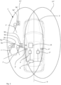
- Fig. 1 is a schematic representation of an exemplary embodiment of an authentication system 1 for a vehicle 2.
- the authentication system 1 comprises a vehicle BLE interface 3 which is arranged on the vehicle 2 in a non-visible manner and surrounded by a panel.
- An optical detection device 4 designed as a time-of-flight camera (TOF camera) is arranged on the B-pillar of the vehicle 2.
- the TOF camera 4 is oriented in the illustration shown such that a detection area 8 of the TOF camera has a central axis which is oriented perpendicular to the plane of symmetry 9 of the vehicle.
- the orientation of the TOF camera 4 is selected such that an operator 7 who is seeking access to the driver's seat 10 of the vehicle 3 inevitably approaches the side door 11 at least temporarily within the detection area 8.
- the authentication system 1 further comprises a vehicle-side control unit 6, which is coupled to both the vehicle BLE interface 3 and the optical detection device 4 and is intended for controlling them.
- a BLE-based communication is carried out between the vehicle BLE interface 3 and the authentication transmitter BLE interface 5b.
- the BLE-based communication is initiated by the authentication transmitter BLE interface 5b sending out an advertise signal in accordance with the specification, which is detected by the vehicle BLE interface 3.
- the vehicle-side control unit 6 recognizes that the authentication transmitter 5a is located within the connection space 12.
- connection space 12 is not to be understood as a statically defined space, since external influences (such as the position of the authentication transmitter 5a, 5a', 5a" on the body of the operator 7, 7', 7") influence the extent of the connection space.
- the vehicle-side control unit 6 controls the TOF camera 4 and causes it to be switched from the state with reduced energy consumption to the operating state.
- the TOF camera 4 can be used to determine whether the operator 7 is within the detection range of the TOF camera 4.
- the operator 7 is within the detection space, while the operator 7" is not within the detection space.
- the triggering of the function can be influenced accordingly.
- an operator located at position 7" results in the vehicle door not being opened, since the position of the operator 7" is interpreted to mean that the operator does not intend to enter the vehicle 2 to take up the driver position 10.
- the TOF camera can now be used to determine the distance the operator is from the vehicle and how the operator's distance changes over time. If the operator advances from position 7 to position 7', this would not be able to be recorded using BLE-based communication or could only be recorded with very high measurement uncertainty. Due to the additional evaluation with the optical detection device 4, the distance at which the operator 7, 7' is located can advantageously be recorded with high precision and, if desired, also time-dependently.
- This provides the vehicle-side control unit 6 with data material for evaluating whether a function should be triggered on the vehicle 2 and which triggering variants are desired.
- the triggering itself and its selection are not part of the invention, but can be implemented based on information obtained using the method according to the invention.
- FIG. 2 An embodiment of the invention is Fig. 2 As shown, the further embodiment has, in addition to the vehicle BLE interface 3' and the optical detection device 4', a second vehicle BLE interface 3" and a second optical detection device 4".
- the optical detection device 4' is designed as a TOF camera that is arranged on the driver-side B-pillar
- the second optical detection device 4" is also designed as a TOF camera that is arranged on the passenger-side B-pillar.
- Fig. 2 In the embodiment of an authentication system 1 shown, it can be provided, for example, that when the operator 7 enters the connection room 12' or when the operator enters the connection room 12", both TOF cameras 4' and 4" are activated in order to determine whether the operator 7 is located within one of the detection areas 8 of one of the two TOF cameras, or whether the operator is instead located outside the two detection areas. However, it can also be provided that when the operator enters the detection room 12', but not the detection room 12", only the optical detection device 4' is controlled for optical position determination or distance determination of the operator.
- a signal strength of a BLE-based communication between the authentication transmitter BLE interface 5b and the vehicle BLE interface 3' as well as a signal strength between the authentication transmitter BLE interface 5b and the vehicle BLE interface 3" is detected and that both are compared with each other. This can be done if the operator is in a location from which BLE communication with several vehicle BLE interfaces is possible.
- the optical detection device 4' is assigned to the vehicle BLE interface 3'. In the embodiment shown, the assignment has the effect that with a stronger signal at the position of the vehicle BLE interface 3', a greater detection success can be expected for the optical detection device 4'.
- the BLE-based communication with the vehicle BLE interface 3" If the BLE-based communication with the vehicle BLE interface 3" is stronger than with the vehicle BLE interface 3', a greater detection success can be expected with the optical detection device 4".
- the one of the at least two optical detection devices is therefore controlled which is assigned to the one of the at least two vehicle BLE interfaces which has achieved the strongest signal strength with the portable authentication transmitter.
Landscapes
- Engineering & Computer Science (AREA)
- Human Computer Interaction (AREA)
- Mechanical Engineering (AREA)
- Lock And Its Accessories (AREA)
Description
- Die Erfindung betrifft ein Verfahren zum Betreiben eines Authentifizierungssystems für ein Kraftfahrzeug.
- Aus dem Stand der Technik sind verschiedene passive Authentifizierungssysteme bekannt, mit denen Funktionen an einem Kraftfahrzeug ausgelöst werden können. Das passive Authentifizieren wird, je nach Hersteller und Fahrzeugtyp, für unterschiedliche Fahrzeugfunktionen genutzt. Beispiele sind das Öffnen von Seitentüren oder der Heckklappe und die Freischaltung des Motorstarts.
- Beispiele für derartige Systeme sind unter den Bezeichnungen Keyless Entry, Keyless Go und Passive Entry Passive Start bekannt.
- Die genannten Systeme basieren auf der Durchführung eines Verifikationsdialogs. Dieser Verifikationsdialog wird zwischen einem portablen Authentifikationsgeber und einer fahrzeugseitigen Infrastruktur durchgeführt. Der portable Authentifikationsgeber befindet sich hierfür in Besitz eines Bedieners. Aus dem Stand der Technik sind insbesondere Funkschlüssel (auch als ID-Geber bezeichnet) bekannt, die mittels kombinierter LF-/HF-Funkkommunikation mit der fahrzeugseitigen Infrastruktur in Kontakt treten und Informationen mit dieser austauschen.
- Derartige passive Authentifizierungssysteme nutzen neben den Authentifizierungsinformationen aus dem Verifikationsdialog in vielen Fällen die Position des Authentifikationsgebers. Die Funktion am Fahrzeug wird in derartigen Ausgestaltungen in Abhängigkeit davon ausgelöst, ob die Position des Authentifikationsgebers mit der angeforderten Funktion plausibel in Einklang steht. So kann beispielsweise ein Starten des Motors an die Voraussetzung geknüpft werden, dass der Authentifikationsgeber sich innerhalb des Fahrzeugs befindet.
- Mit der zunehmenden Verbreitung und fortschreitenden Weiterentwicklung von Bluetooth-Kommunikation wird deren Einbindung in Authentifizierungssysteme für Fahrzeuge zunehmend attraktiv. Dadurch, dass Bluetooth in vielen elektronischen Geräten, wie beispielsweise Smartphones, bereits implementiert ist, geht die Bereitstellung von Bluetooth-Komponenten mit einem großen Komfort für den Bediener einher und ist dementsprechend gewünscht.
- Ein Beispiel für ein Kraftfahrzeugzugangssystem, welches auf der Nutzung von Bluetooth Low Energy basiert, ist der
WO 2017/066286 A1 zu entnehmen. - Mit Hinblick auf die Positionsbestimmung weist die Nutzung von Bluetooth-Kommunikation aufgrund der genutzten Frequenzen jedoch prinzipbedingt den Nachteil auf, dass die Ortsauflösung vergleichsweise gering ist. Ein weiteres Problem besteht darin, dass aufgrund von Abschirmeffekten die Reproduzierbarkeit der Positionsbestimmung unter Nutzung der Bluetooth-Kommunikation begrenzt ist.
- Die Aufgabe der Erfindung besteht daher darin, ein verbessertes Verfahren zum Betreiben eines Authentifizierungssystems für ein Fahrzeug bereitzustellen, mit welchem die oben genannten Nachteile überwunden oder zumindest vermindert werden.
- Die Aufgabe wird gelöst mit einem Verfahren zum Betrieb eines Authentifizierungssystems für ein Fahrzeug mit den Merkmalen des Anspruchs 1.
- Vorteilhafte und zweckmäßige Weiterbildungen und Ausgestaltungen der Erfindung ergeben sich aus den Unteransprüchen.
- Das erfindungsgemäße Verfahren nutzt zumindest zwei Fahrzeug-BLE-Schnittstellen, die an dem Fahrzeug angeordnet ist. Der Begriff der BLE-Schnittstelle bezieht sich dabei auf Bluetooth Low Energy. Bei Bluetooth Low Energy handelt es sich um ein Kommunikationsverfahren, welches in einer der Bluetooth-Spezifikationen definiert ist, welche die Versionsnummer 4.0 oder höher aufweisen. Die Bluetooth-Spezifikationen werden von dem Bluetooth-Konsortium bereitgestellt, beispielsweise unter https://www.bluetooth.com/specifications/adopted-specifications.
- Der Begriff der BLE-Schnittstelle bezeichnet ein Element oder eine Gruppe von Elementen, welches beziehungsweise welche zur Kommunikation im Sinne der BLE-Übertragungstechnologie in der Lage ist bzw. sind. Der Begriff der BLE-Schnittstelle umfasst sämtliche körperlichen und unkörperlichen Bestandteile, welche für eine BLE-Kommunikation mit einem anderen für BLE-Kommunikation vorgesehenen Gerät erforderlich sind. Insbesondere umfasst der Begriff der BLE-Schnittstelle auch Sende- und/oder Empfangsmittel, wie beispielsweise eine entsprechende Antenne. Auch gegebenenfalls erforderliche, als Software vorliegende, Treiber sind umfasst.
- Die Verwendung des BLE-Übertragungsprotokolls befähigt das Fahrzeug dazu, ein Authentifizierungssystem mit einem breiten Spektrum unterschiedlicher Gegengeräte vorzusehen. Insbesondere die gegenwärtig sehr weitgehende Umsetzung der BLE-Spezifikation in Smartphones führt dazu, dass eine Vielzahl von potentiellen Gegengeräten bereitsteht, die individuell für eine Verwendung mit dem Authentifizierungssystem genutzt werden können. Dadurch, dass die BLE-Kommunikation mit vergleichsweise geringem Energieumsatz genutzt werden kann, sind aber neben beispielsweise Smartphones auch eigens für das Authentifizierungssystem vorgesehene individuell angepasste Gegengeräte vorstellbar.
- Zusätzlich zu der Fahrzeug-BLE-Schnittstelle sind an dem Fahrzeug zumindest zwei optische Erfassungsvorrichtungen angeordnet.
- Die optische Erfassungsvorrichtung erfüllt wenigstens die Anforderung, dass unter Nutzung eines optischen Wirkprinzips die Anwesenheit oder die Nichtanwesenheit eines Bedieners in einer Umgebung der optischen Erfassungsvorrichtung festgestellt werden kann. Die optische Erfassungsvorrichtung kann insbesondere dem Zweck dienen, dem Fahrzeug Informationen über die Lage, Position und/oder den Abstand eines Bedieners von der optischen Erfassungsvorrichtung zu liefern. Diese zusätzlichen Informationen können sodann im Rahmen eines Verifikationsprozesses genutzt werden. Beispielsweise kann die Plausibilität einer jeweils angeforderten Funktion geprüft werden. Auch kann die erfolgreiche Authentifizierung als Bedingung vorsehen, dass der Benutzer eine bestimmte Position aufweist.
- Der Begriff der Position ist im Zusammenhang dieser Anmeldung nicht notwendigerweise im Sinne einer vollständigen Ortsermittlung zu verstehen, sondern kann in Zusammenhang mit der im Bezugssystem Fahrzeug bekannten Position und Orientierung der optischen Erfassungsvorrichtung auch als Relativposition verstanden werden. Wesentlich ist, dass mittels der optischen Erfassungsvorrichtung kraftfahrzeugseitig präzisere Informationen über die Position des Bedieners relativ zu dem Kraftfahrzeug erlangt werden als mit der Nutzung der Fahrzeug-BLE-Schnittstelle allein.
- Als Gegengerät ist ein portabler Authentifikationsgeber vorgesehen, welcher eine Authentifikationsgeber-BLE-Schnittstelle aufweist. Der Authentifikationsgeber ist also in der Lage, mit der Fahrzeug-BLE-Schnittstelle gemäß einer BLE-Spezifikation Daten beziehungsweise Informationen auszutauschen. Der Authentifikationsgeber weist zumindest Identitätsdaten auf, welche zum Nachweis einer Berechtigung zum Auslösen einer Funktion gegenüber dem Fahrzeug dienen, beispielsweise gegenüber dem fahrzeugseitigen Steuergerät.
- Dadurch, dass der Authentifikationsgeber zumindest mit den auf ihm hinterlegten Identitätsdaten auf das Fahrzeug angepasst ist, ist der Authentifikationsgeber Bestandteil des Authentifizierungssystems.
- Das Verfahren sieht die folgenden Schritte vor:
- Durchführen einer BLE-basierten Kommunikation zwischen der Fahrzeug-BLE-Schnittstelle und der Authentifikationsgeber-BLE-Schnittstelle;
- fahrzeugseitiges Auswerten der BLE-basierten Kommunikation;
- Ansteuerung der optischen Erfassungsvorrichtung in Abhängigkeit von der Auswertung der BLE-basierten Kommunikation zur optischen Positionsbestimmung oder Entfernungsbestimmung eines Bedieners, der den portablen Authentifikationsgeber mit sich führt.
- Das Durchführen der BLE-basierten Kommunikation kann je nach Implementierung des Verfahrens ein zuvor erfolgendes Pairing voraussetzen, ein Pairing im Laufe der Kommunikation umfassen oder auch ohne ein Pairing im Rahmen der Verbindungsanbahnung erfolgen.
- Die optische Erfassungsvorrichtung und die Fahrzeug-BLE-Schnittstelle sind zur Durchführung des Verfahrens miteinander gekoppelt. Es kann vorgesehen sein, dass die Fahrzeug-BLE-Schnittstelle unmittelbar mit der optischen Erfassungsvorrichtung gekoppelt ist. Beispielsweise kann vorgesehen sein, dass die optische Erfassungsvorrichtung und die Fahrzeug-BLE-Schnittstelle als ein Modul ausgebildet sind. Es kann aber auch vorgesehen sein, dass die Fahrzeug-BLE-Schnittstelle und optische Erfassungsvorrichtung an unterschiedlichen Positionen des Fahrzeugs angeordnet sind und die beiden miteinander nur mittelbar, beispielsweise über ein fahrzeugseitiges Steuergerät, miteinander gekoppelt sind. Insbesondere kann auch vorgesehen sein, dass die Ansteuerung der optischen Erfassungsvorrichtung in Abhängigkeit von der Auswertung der BLE-basierten Kommunikation durch das fahrzeugseitige Steuergerät vorgenommen wird.
- Die Ansteuerung der optischen Erfassungsvorrichtung dient dem Zweck, zur optischen Positionsbestimmung oder Entfernungsbestimmung eines Bedieners beizutragen, der den portablen Authentifikationsgeber mit sich führt.
- Die Erfindung dient nicht primär der Erfassung der Position des Authentifikationsgebers, sondern der Erfassung der Position des Bedieners. Es wird also die Annahme getroffen, dass der Bediener im Besitz des Authentifikationsgebers ist. Aus dieser Annahme heraus wird die Auswertung der BLE-basierten Kommunikation mit dem Authentifikationsgeber als valide Ausgangsbasis für die Ansteuerung der optischen Erfassungsvorrichtung angesehen und entsprechend genutzt.
- Mit dem erfindungsgemäßen Verfahren wird also eine Nutzung einer optischen Erfassungsvorrichtung kombiniert mit Ergebnissen, die aus einer BLE-basierten Kommunikation erhalten oder abgeleitet werden. Insbesondere können die aus der BLE-basierten Kommunikation gewonnenen Daten als Ausgangspunkt für die Ansteuerung der optischen Erfassungsvorrichtung genutzt werden.
- Dies kann beispielsweise die Entscheidung umfassen,
- ob überhaupt Daten der optischen Erfassungsvorrichtung benötigt werden;
- welche optische Erfassungsvorrichtung ausgewählt wird, sofern mehrere optische Erfassungsvorrichtungen am Fahrzeug angeordnet sind;
- mit welchen Einstellungen die optische
- Erfassungsvorrichtung genutzt wird, beispielsweise mit welchem Richtwinkel, sofern dieser einstellbar ist.
- In der Durchführung des Verfahrens ergibt sich aus der Gesamtheit der vorgenannten erfindungsgemäßen Maßnahmen der Vorteil, dass optisch erfasste Daten kombiniert werden können mit Daten, welche aus der BLE-Kommunikation erhalten wurden. Denn beide Methoden zur Gewinnung von Daten weisen spezifische Vorteile auf.
- Das Verfahren zum Betreiben eines Authentifizierungssystems sieht bevorzugt auch einen Schritt des Verifizierungsdialogs vor; dies ist jedoch für die Erfindung nicht wesentlich.
- Gemäß einer Weiterbildung des Verfahrens kann vorgesehen sein, dass die optische Erfassungsvorrichtung sich in einem Zustand mit reduzierter Energieaufnahme befindet. Ferner ist vorgesehen, dass die optische Erfassungsvorrichtung aus diesem Zustand mit reduzierter Energieaufnahme in einen Betriebszustand versetzt wird, nachdem die Auswertung der BLE-basierten Kommunikation ergeben hat, dass der portable Authentifikationsgeber sich innerhalb eines vorgegebenen Raums um die Fahrzeug-BLE-Schnittstelle befindet. Das Vorhandensein des Authentifikationsgebers innerhalb des vorgegebenen Raums ist gemäß dieser Weiterbildung also zumindest notwendige Bedingung dafür, dass die optische Erfassungsvorrichtung in ihren Betriebszustand versetzt wird. Der Begriff des vorgegebenen Raums repräsentiert dabei einen Parameter oder eine Kombination von Parametern, welche beispielsweise eine absolute Position, eine relative Position, eine absolute Lage, eine relative Lage und/oder eine Beabstandung definieren oder teilweise definieren.
- In einem einfachen Fall kann bereits die Tatsache, dass ein bestimmter Authentifikationsgeber, welcher dem Fahrzeug vorbekannt ist, einen Verbindungsversuch mit der Fahrzeug-BLE-Schnittstelle anstrengt, aufgefasst werden als Erfassung des Authentifikationsgebers innerhalb eines vorgegebenen Raums.
- Dadurch, dass Positions- und/oder Entfernungsinformationen aus einer BLE-basierten Kommunikation genutzt werden, wird die Betriebsaufnahme der optischen Erfassungsvorrichtung nur in solchen Fällen veranlasst, in denen die Notwendigkeit derer Benutzung erwartet wird. Die mit der Verwendung der optischen Erfassungsvorrichtung einhergehende Energieaufnahme wird durch diese Maßnahme reduziert.
- Gemäß einer Weiterbildung des Verfahrens umfasst das Auswerten der BLE-basierten Kommunikation die Annäherungserkennung der Authentifikationsgeber-BLE-Schnittstelle innerhalb eines Verbindungsraums um die Fahrzeug-BLE-Schnittstelle. Dies bedeutet, dass die Fahrzeug-BLE-Schnittstelle schlicht erkennt, dass eine Authentifikationsgeber-BLE-Schnittstelle, die bevorzugt vorbekannt ist, sich innerhalb der Kommunikationsreichweite der Fahrzeug-BLE-Schnittstelle befindet. Dies kann beispielsweise erfolgen, indem die Fahrzeug-BLE-Schnittstelle ein Advertise-Signal der Authentifikationsgeber-BLE-Schnittstelle empfängt und als solche erkennt.
- Bevorzugt wird gemäß einer Weiterbildung die optische Erfassungsvorrichtung zur Erfassung des Abstands des Bedieners angesteuert, wenn eine Verbindung zwischen der Authentifikationsgeber-BLE-Schnittstelle und der Fahrzeug-BLE-Schnittstelle etabliert ist. Zusätzlich kann die Bedingung gefordert sein, dass die etablierte Verbindung während einer vorgegebenen Mindestverbindungsdauer tV etabliert bleibt. Dadurch, dass eine etablierte Verbindung zwischen den beiden BLE-Schnittstellen gefordert ist, wird eine Möglichkeit bereitgestellt, den Betrieb des Authentifizierungssystems auf gewünschte BLE-Schnittstellen einzuschränken. Dadurch, dass zusätzlich zu dem Etablieren der Verbindung auch das Aufrechterhalten der etablierten Verbindung während der vorgegebenen Mindestverbindungsdauer gefordert ist, wird mit Mitteln, die in der BLE-Spezifikation verankert sind, mit zumindest einer gewissen Genauigkeit eine Bestätigung herbeigeführt, dass der Bediener ohne Unterbrechung in einem umgrenzten Umkreis um das Fahrzeug verbleibt. Durch bedarfsgerechte Wahl der vorgegebenen Mindestverbindungsdauer kann, je nach erwartetem Szenario, dadurch ein unnötiges Einschalten beziehungsweise Ansteuern der optischen Erfassungsvorrichtung vermieden oder weitgehend vermieden werden. Weiterhin kann durch entsprechendes Einstellen der Mindestverbindungsdauer tV erreicht werden, dass die optische Erfassungsvorrichtung nicht zu frühzeitig vor ihrer eigentlichen Verwendung eingeschaltet wird.
- Erfindungsgemäß umfasst das Auswerten der BLE-basierten Kommunikation eine Bestimmung einer Signalstärke der BLE-basierten Kommunikation. Insbesondere kann eine Signalstärke der BLE-basierten Kommunikation am Ort der Authentifikationsgeber-BLE-Schnittstelle ermittelt werden. Alternativ oder zusätzlich kann eine Signalstärkenerfassung der BLE-basierten Kommunikation am Ort der Fahrzeug-BLE-Schnittstelle vorgesehen sein. Auch eine Kombination von beidem kann vorgesehen sein.
- Zur Signalstärkeermittlung kann insbesondere eine spezifikationsgemäße RSSI-Wert-Ermittlung genutzt werden.
- Ob eine Auswertung der erfassten Signalstärken innerhalb des Authentifikationsgebers, innerhalb einer fahrzeugseitigen Einrichtung (wie beispielsweise dem fahrzeugseitigen Steuergerät) oder in beiden erfolgt, kann bedarfsweise im Rahmen der Implementierung des Verfahrens berücksichtigt werden.
- Ergänzend kann vorgesehen sein, dass die optische Erfassungsvorrichtung zur Erfassung des Abstands des Bedieners angesteuert wird, nachdem die Signalstärke der BLE-basierten Kommunikation einen vorgegebenen Grenzwert erreicht hat und für eine vorgegebene Mindestdauer tG gehalten oder überschritten hat. Es kann also ein Schwellwert vorgesehen sein, welcher ununterbrochen überschritten sein muss, bevor die optische Erfassungsvorrichtung angesteuert wird. Ob die Auswertung der Signalstärke abgetastet erfolgt, eine Mittelwertbildung erfolgt oder ähnliche Auswertealgorithmen genutzt werden, ist vom Verwendungszweck und beispielsweise von gewünschter Latenzzeit und tolerierter Fehleranfälligkeit abhängig. Wesentlich ist, dass mit Berücksichtigung eines Grenzwerts tG mit verbesserter Genauigkeit erkannt wird, wenn der Authentifikationsgeber sich dem Fahrzeug annähert und in einem begrenzten Umkreis des Fahrzeugs verbleibt, woraus auf einen Auslösewillen des Bedieners geschlossen wird.
- Ergänzend ist erfindungsgemäß für das Ansteuern der optischen Erfassungsvorrichtung die Voraussetzung gefordert, dass die Signalstärke der BLE-basierten Kommunikation sich nach einer vorgegebenen Zeitdauer tD zwischen ihrem Maximalwert und ihrem Minimalwert um weniger als eine Maximaldifferenz Deltamax geändert hat. So kann zusätzlich zu den bereits genannten Bedingungen die Auswertung auf einen möglichen stationären Verbleib des Bedieners innerhalb eines begrenzten Korridors hin verbessert werden.
- Erfindungsgemäß ist vorgesehen,
- dass an dem Fahrzeug die Fahrzeug-BLE-Schnittstelle und ferner zumindest eine zweite Fahrzeug-BLE-Schnittstelle angeordnet ist,
- dass an dem Fahrzeug die optische Erfassungsvorrichtung und zumindest eine zweite Erfassungsvorrichtung vorgesehen ist,
- dass die Fahrzeug-BLE-Schnittstelle der optischen Erfassungsvorrichtung zugeordnet ist, und
- dass die zweite Fahrzeug-BLE-Schnittstelle der zweiten optischen Erfassungsvorrichtung zugeordnet ist.
- Es ist also eine Konstellation vorgesehen, in der sowohl von den Fahrzeug-BLE-Schnittstellen als auch von den optischen Erfassungsvorrichtungen jeweils wenigstens zwei Exemplare vorgesehen sind. Jeder der wenigstens zwei Fahrzeug-BLE-Schnittstellen ist jeweils eine andere der optischen Erfassungsvorrichtungen zugeordnet.
- Erfindungsgemäß wird diejenige der wenigstens zwei optischen Erfassungsvorrichtungen angesteuert, welche derjenigen der wenigstens zwei Fahrzeug-BLE-Schnittstellen zugeordnet ist, welche innerhalb eines vorgegebenen Zeitraums tS die BLE-basierte Kommunikation durchgeführt hat, für welche die stärkste Signalstärke mit dem portablen Authentifikationsgeber ermittelt wurde.
- Mit anderen Worten wird während des vorgegebenen Zeitraums tS die Signalstärke der BLE-basierten Kommunikation mit jeder der beiden Fahrzeug-BLE-Schnittstellen ausgewertet. Wesentlich ist, dass der Vergleich von Signalstärken der BLE-basierten Kommunikation an verschiedenen Fahrzeug-BLE-Schnittstellen, die an verschiedenen Positionen des Fahrzeugs lokalisiert sind, genutzt wird, um diejenige von mehreren vorhandenen optischen Erfassungsvorrichtungen auszuwählen, für welche der größtmögliche Erfolg einer optischen Erfassung des Bedieners zu erwarten ist. Für die Zuordnung der Fahrzeug-BLE-Schnittstellen zu den Authentifikationsgeber-Schnittstellen kann vorgesehen sein, dass die Fahrzeug-BLE-Schnittstelle weniger von der optischen Erfassungsvorrichtung als von der zweiten optischen Erfassungsvorrichtung beabstandet ist, und dass die zweite Fahrzeug-BLE-Schnittstelle weniger von der zweiten optischen Erfassungsvorrichtung als von der optischen Erfassungsvorrichtung beabstandet ist. Die Zuordnung erfolgt in dieser Ausgestaltung nach dem geringsten Abstand von Fahrzeug-BLE-Schnittstelle und von optischer Erfassungsvorrichtung, wobei der Abstand im mathematischen Sinne als Länge der Strecke zwischen Fahrzeug-BLE-Schnittstelle und optischer Erfassungsvorrichtung zu verstehen ist. Das erfindungsgemäße Verfahren kann dahingehend weitergebildet sein, dass diejenige der wenigstens zwei optischen Erfassungsvorrichtungen angesteuert wird, welche derjenigen der wenigstens zwei Fahrzeug-BLE-Schnittstellen am nächsten ist, welche innerhalb eines vorgegebenen Zeitraums tS die BLE-basierte Kommunikation mit der stärksten Signalstärke mit dem portablen Authentifikationsgeber durchgeführt hat. Die BLE-Kommunikation, die mit geringer Energieaufnahme zu betreiben ist, aber eine geringe Genauigkeit in der Positionsbestimmung erlaubt, trägt also zu einer Grobermittlung der Position des Bedieners bei.
- Diese Grobermittlung wird sodann genutzt, um durch gezielte Auswahl von einer der vorhandenen optischen Erfassungsvorrichtungen ein gutes Ergebnis der optischen Positions- oder Entfernungsbestimmung des Bedieners zu erreichen. Dadurch, dass eine gezielte Auswahl der optischen Erfassungsvorrichtung erfolgt, wird die Erfassungsqualität verbessert und dadurch beispielsweise die Anzahl von Fehlauslösungen reduziert und die für optische Erfassung aufzuwendende Energie reduziert. Als optische Erfassungsvorrichtung können beispielsweise ein Laserinterferometer, eine laserbasierte Laufzeiterfassungsvorrichtung oder eine Time-of-Flight-Kamera vorgesehen sein. Auch kombinierte Anordnungen aus mehreren von diesen können vorgesehen sein. Die Position der optischen Erfassungsvorrichtung oder der optischen Erfassungsvorrichtungen kann dahingehend ausgewählt werden, wo eine Annäherung des Bedieners am ehesten zu erwarten ist. Beispielsweise kann vorgesehen sein, dass eine optische Erfassungsvorrichtung im Fahrzeuggriff, in der B-Säule, in einer oder mehrerer der Seitentüren, im Seitenspiegel und/oder an der Heckklappe angeordnet ist. Die optische Erfassungsvorrichtung ist bevorzugt derart ausgerichtet, dass der Abstand des Bedieners von einer der Seitentüren und/oder von der Heckklappe erfassbar ist. Insbesondere kann auch vorgesehen sein, dass die optische Erfassungsvorrichtung innerhalb des Fahrzeugs angeordnet ist und derart ausgerichtet ist, dass die Anwesenheit des Bedieners auf einer Fahrerposition verifiziert werden kann. Gemäß einer Ausgestaltung der Erfindung kann ferner vorgesehen sein, dass die Erfassungsvorrichtung nach ihrem Ansteuern einen Erfassungsbereich erfasst, der von der Erfassungsvorrichtung abgedeckt wird, und dadurch eine oder mehrere Authentifikationsaufnahmen generiert. Bei den Aufnahmen handelt es sich um mit der Erfassungsvorrichtung erfasste Daten, die zeitaufgelöst oder zu einem einzigen Zeitpunkt vorliegen können.
- Die Art der Daten hängt von der Ausgestaltung der Erfassungsvorrichtung ab. Bei als Time-Of-Flight-3D-Kamera ausgebildeter Erfassungsvorrichtung kann es sich beispielsweise um eine 3D-Fotografie oder um eine zeitabhängige Sequenz von 3D-Fotografien handeln.
- Gemäß dieser Weiterbildung werden die erfassten Daten mittels eines fahrzeugseitigen Steuergeräts ausgewertet. Die durchgeführte Auswertung kann eine oder mehrere der nachfolgend genannten umfassen:
Es kann ausgewertet werden, ob ein Bediener in seiner Hand ein Smartphone hält. Dies kann bei Nutzung einer Time-Of-Flight-3D-Kamera mittels Objekterkennung erfolgen. - Es kann ausgewertet werden, ob die erfassten Daten einen Verifikationscode zeigen, der von dem Steuergerät als berechtigend identifiziert wird. Beispielsweise kann mittels der Erfassungsvorrichtung ein auf einem Smartphone-Display angezeigter zwei- oder dreidimensionaler Barcode, insbesondere ein QR-Code, erfasst und ausgewertet werden, der beispielsweise in Reaktion auf die BLE-Kommunikation von dem Smartphone angezeigt wird und dieses identifiziert.
- Es kann die Durchführung einer Bediengeste ausgewertet werden und mit kraftfahrzeugseitig hinterlegten Referenzgesten verglichen werden. Die Bediengeste kann, je nach Umsetzung des Verfahrens, dem Auslösen einer Funktion dienen oder alternativ oder zusätzlich zur Verifikation der Berechtigung des Bedieners beitragen. Die Verifikation der Berechtigung wird durch die Bediengeste unterstützt, wenn eine unintuitiv durchzuführende und als ausreichend komplex angesehene Bediengeste vorgesehen ist. Auch können separat voneinander Bediengesten und Berechtigungsgesten vorgesehen sein. Ferner kann vorgesehen sein, dass für unterschiedliche Benutzer unterschiedliche Bediengesten und/oder unterschiedliche Berechtigungsgesten vorgesehen sind.
- Es kann ein in dem Erfassungsbereich befindliches Gesicht des Bedieners aufgenommen werden und anhand kraftfahrzeugseitig hinterlegter Referenzdaten auf die Berechtigung des Bedieners hin geprüft werden. Dies bietet sich insbesondere bei als Time-Of-Flight-3D-Kamera ausgebildeter Erfassungsvorrichtung an.
- Dadurch, dass also eine Abbildung des Bedieners oder einer im Besitz des Bedieners vorhandenen Einrichtung oder auch einer Aktion des Bedieners ausgewertet wird, kann der Verifikationsprozess sicherer und zuverlässiger durchgeführt werden.
- Gemäß einer Weiterbildung kann vorgesehen sein, dass der Authentifikationsgeber dem Fahrzeug Identifikationsdaten übermittelt, die von dem fahrzeugseitigen Steuergerät ausgewertet werden. Die Auswertung umfasst, ob die Identifikationsdaten mit aus der Authentifikationsaufnahme abgeleiteten Verifikationsdaten als zueinander gehörend verifiziert werden können. Dies bedeutet, dass das Kraftfahrzeug eine Verbindung zwischen Identifikationsdaten und Eigenschaften des Bedieners oder von ihm durchgeführten Aktionen kennt und prüft, ob die Identifikationsdaten zu den Verifikationsdaten passend sind. Durch diese Prüfung wird die Sicherheit des Verfahrens weiter erhöht, da beispielsweise in dem Fall eines Diebstahls des Authentifikationsgeräts eine Verifikation unterbleiben würde, wenn beispielsweise nicht das erwartete Gesicht des Bedieners von der Erfassungseinrichtung erkannt wird.
- Die Identifikationsdaten können derart mit Verifikationsdaten in funktioneller Relation stehen, dass kraftfahrzeugseitig die Verifikationsdaten nicht bekannt sind, aber korrekte Identifikationsdaten und Verifikationsdaten mit genügender Sicherheit als zueinander gehörig erkannt werden. Beispielsweise können die Identifikationsdaten derart eingerichtet werden, dass sie und die Verifikationsdaten zueinander gehörige, insbesondere gleiche, Hash-Werte aufweisen.
- Dadurch, dass die Identifikationsdaten mittels BLE-Übertragung und die Verifikationsdaten mittels optischer Erfassung übertragen werden, liegt eine Trennung der Kanäle vor, wodurch eine weiter verbesserte Sicherheit des Verfahrens erreicht werden kann.
- Ein anderer Gedanke betrifft ein Authentifizierungssystem für ein Fahrzeug. Das Authentifizierungssystem für ein Fahrzeug weist dabei die eingangs im Zusammenhang mit dem erläuterten Verfahren vorgesehenen Anordnungen auf. Das Authentifizierungssystem weist ferner ein Steuergerät auf, das mit der Fahrzeug-BLE-Schnittstelle und mit der optischen Erfassungsvorrichtung gekoppelt ist und eingerichtet ist, das erfindungsgemäße Verfahren oder eine seiner Weiterbildungen durchzuführen.
- Ein weiterer Gedanke sieht eine Verwendung eines Authentifizierungssystems der oben genannten Art zur Entfernungsbestimmung eines Bedieners mit einem portablen Authentifikationsgeber vor. Zur Entfernungsbestimmung ist vorgesehen, dass die optische Erfassungsvorrichtung mittels des Steuergeräts eingeschaltet wird, wenn nach einer BLE-basierten Kommunikation zwischen der Fahrzeug-BLE-Schnittstelle und der Authentifikationsgeber-BLE-Schnittstelle eine fahrzeugseitige Auswertung der BLE-basierten Kommunikation feststellt, dass die BLE-basierte Kommunikation eine Anwesenheit des portablen Authentifikationsgebers innerhalb eines vorgegebenen Raums um die Fahrzeug-BLE-Schnittstelle repräsentiert. Mit anderen Worten wird die optische Erfassungsvorrichtung eingeschaltet, sobald die Auswertung der BLE-basierten Kommunikation eine Anwesenheit des Bedieners in einem Erfassungsbereich der optischen Erfassungsvorrichtung möglich erscheinen lässt.
- Mit dem Authentifizierungssystem und der Verwendung des Authentifizierungssystems gehen die erläuterten Vorteile des erfindungsgemäßen Verfahrens und seiner Weiterbildungen in analoger Weise einher.
- Weitere Einzelheiten, Merkmale und Vorteile des Gegenstands der Erfindung ergeben sich aus der nachfolgenden Beschreibung im Zusammenhang mit der Zeichnung, in welcher beispielhaft ein Ausführungsbeispiel der Erfindung dargestellt ist.
- Es versteht sich, dass die vorstehend genannten wie auch nachfolgend erläuterten Merkmale nicht nur in der jeweils angegebenen Kombination, sondern auch in anderen Kombinationen oder in Alleinstellung verwendbar sind.
- Es zeigen:
-
Fig. 1 : eine schematische Darstellung einer beispielhaften Ausgestaltung eines Authentifizierungssystems; -
Fig. 2 : eine schematische Darstellung einer erfindungsgemäßen Ausführungsform eines Authentifizierungssystems. -
Fig. 1 ist eine schematische Darstellung einer beispielhaften Ausgestaltung eines Authentifizierungssystems 1 für ein Fahrzeug 2 zu entnehmen. Das Authentifizierungssystems 1 umfasst eine Fahrzeug-BLE-Schnittstelle 3 die nicht sichtbar und von einer Verkleidung umgeben an dem Fahrzeug 2 angeordnet ist. An der B-Säule des Fahrzeugs 2 ist eine als Time-of-Flight-Kamera (TOF-Kamera) ausgebildete optische Erfassungsvorrichtung 4 angeordnet. Die TOF-Kamera 4 ist in der gezeigten Darstellung derart orientiert, dass ein Erfassungsbereich 8 der TOF-Kamera eine Zentralachse aufweist, die senkrecht zur Symmetrieebene 9 des Fahrzeugs orientiert ist. Die Orientierung der TOF-Kamera 4 ist derart gewählt, dass ein Bediener 7, der Zugang zum Fahrersitz 10 des Fahrzeugs 3 sucht, sich unvermeidlich zumindest zeitweise innerhalb des Erfassungsbereichs 8 der Seitentür 11 nähert. Das Authentifizierungssystem 1 weist ferner ein fahrzeugseitiges Steuergerät 6 auf, das sowohl mit der Fahrzeug-BLE-Schnittstelle 3 als auch mit der optischen Erfassungsvorrichtung 4 gekoppelt ist und für deren Steuerung vorgesehen ist. - Wenn der Bediener 7 in den Verbindungsraum 12 um die Fahrzeug-BLE-Schnittstelle 3 eintritt, und dabei einen portablen Authentifikationsgeber 5a mit einer Authentifikationsgeber-BLE-Schnittstelle 5b mit sich führt, wird eine BLE-basierte Kommunikation zwischen der Fahrzeug-BLE-Schnittstelle 3 und der Authentifikationsgeber-BLE-Schnittstelle 5b durchgeführt. In der dargestellten Ausgestaltung erfolgt die Aufnahme der BLE-basierten Kommunikation dadurch, dass die Authentifikationsgeber-BLE-Schnittstelle 5b spezifikationsgemäß ein Advertise-Signal aussendet, welches von der Fahrzeug-BLE-Schnittstelle 3 erfasst wird. Dadurch, dass die BLE-basierte Kommunikation durchgeführt wird, erkennt das fahrzeugseitige Steuergerät 6, dass der Authentifikationsgeber 5a sich innerhalb des Verbindungsraums 12 befindet. Der Verbindungsraum 12 ist nicht als statisch definierter Raum zu verstehen, da äußere Einflüsse (wie beispielsweise die Position des Authentifikationsgebers 5a, 5a', 5a" am Körper des Bedieners 7, 7', 7") die Ausdehnung des Verbindungsraums beeinflussen. Als Folge der Annäherungserkennung des Authentifikationsgebers 5a durch die Fahrzeug-BLE-Schnittstelle 3 steuert das fahrzeugseitige Steuergerät 6 die TOF-Kamera 4 an und veranlasst, dass diese aus dem Zustand mit reduzierter Energieaufnahme in den Betriebszustand versetzt wird. Mittels der TOF-Kamera 4 kann zum einen ermittelt werden, ob der Bediener 7 sich innerhalb des Erkennungsbereichs der TOF-Kamera 4 befindet. Der Bediener 7 befindet sich innerhalb des Erkennungsraums, während der Bediener 7" sich nicht innerhalb des Erkennungsraum befindet. Abhängig davon, ob der Bediener sich an der Position 7 oder an der Position 7" befindet, kann entsprechend ein Auslösen der Funktion beeinflusst werden. Beispielsweise kann vorgesehen sein, dass ein an Position 7" befindlicher Bediener dazu führt, dass kein Öffnen der Fahrzeugtür veranlasst wird, da die Position des Bedieners 7" dahingehend interpretiert wird, dass der Bediener keinen Eintritt in das Fahrzeug 2 zum Einnehmen der Fahrerposition 10 beabsichtigt. An der Position 7 befindlich kann mittels der TOF-Kamera nun ermittelt werden, welchen Abstand der Bediener zu dem Fahrzeug einnimmt und wie der Abstand des Bedieners sich zeitlich verändert. Wenn der Bediener von der Position 7 zu der Position 7' vorrückt, würde dies mittels BLE-basierter Kommunikation nicht oder nur mit sehr hoher Messunsicherheit erfasst werden können. Aufgrund der zusätzlichen Auswertung mit der optischen Erfassungsvorrichtung 4 kann in vorteilhafter Weise mit hoher Präzision und, sofern gewünscht auch zeitabhängig, erfasst werden, in welchem Abstand der Bediener 7, 7' sich befindet. Dadurch wird dem fahrzeugseitigen Steuergerät 6 Datenmaterial bereitgestellt zur Auswertung, ob eine Funktion am Fahrzeug 2 ausgelöst werden soll und welche Auslösevarianten gewünscht sind. Die Auslösung selbst sowie deren Auswahl ist nicht Bestandteil der Erfindung, sondern kann implementiert werden basierend auf Informationen, die unter Nutzung des erfindungsgemäßen Verfahrens gewonnen werden.
- Eine Ausführungsform der Erfindung ist
Fig. 2 zu entnehmen. Wie dargestellt ist, weist die weitere Ausgestaltung zusätzlich zu der Fahrzeug-BLE-Schnittstelle 3' und der optischen Erfassungsvorrichtung 4' eine zweite Fahrzeug-BLE-Schnittstelle 3" und eine zweite optische Erfassungsvorrichtung 4" auf. Die optische Erfassungsvorrichtung 4' ist als TOF-Kamera ausgebildet, die an der fahrerseitigen B-Säule angeordnet ist, die zweite optische Erfassungsvorrichtung 4" ist ebenfalls als TOF-Kamera ausgebildet, die an der beifahrerseitigen B-Säule angeordnet ist. - Mit der in
Fig. 2 dargestellten Ausführungsform eines Authentifizierungssystems 1 kann beispielsweise vorgesehen werden, dass bei Eintritt des Bedieners 7 in den Verbindungsraum 12' oder bei Eintritt des Bedieners in den Verbindungsraum 12" beide TOF-Kameras 4' und 4" aktiviert werden, um festzustellen, ob der Bediener 7 innerhalb eines der Erfassungsbereiche 8 einer der beiden TOF-Kameras befindlich ist, oder ob der Bediener stattdessen außerhalb der beiden Erfassungsbereiche befindlich ist. Es kann aber auch vorgesehen sein, dass bei Eintritt des Bedieners in den Erfassungsraum 12', nicht aber in den Erfassungsraum 12" ausschließlich die optische Erfassungsvorrichtung 4' angesteuert wird zur optischen Positionsbestimmung oder Entfernungsbestimmung des Bedieners. Es ist vorgesehen, dass eine Signalstärke einer BLE-basierten Kommunikation zwischen der Authentifikationsgeber-BLE-Schnittstelle 5b und der Fahrzeug-BLE-Schnittstelle 3' sowie eine Signalstärke zwischen der Authentifikationsgeber-BLE-Schnittstelle 5b und der Fahrzeug-BLE-Schnittstelle 3" erfasst wird und dass beide miteinander verglichen werden. Auf diese Weise kann verfahren werden, wenn der Bediener sich an einem Ort befindet, von dem aus eine BLE-Kommunikation mit mehreren Fahrzeug-BLE-Schnittstellen möglich ist. Die optische Erfassungsvorrichtung 4' ist der Fahrzeug-BLE-Schnittstelle 3' zugeordnet. Die Zuordnung wirkt sich in der dargestellten Ausführungsform derart aus, dass bei stärkerem Signal an der Position der Fahrzeug-BLE-Schnittstelle 3' ein größerer Erfassungserfolg für die optische Erfassungsvorrichtung 4' erwartet werden kann. Analoges gilt für die BLE-basierte Kommunikation mit der Fahrzeug-BLE-Schnittstelle 3" : Wenn die BLE-basierte Kommunikation mit der Fahrzeug-BLE-Schnittstelle 3" stärker ist als mit der Fahrzeug-BLE-Schnittstelle 3', ist ein größerer Erfassungserfolg mit der optischen Erfassungsvorrichtung 4" zu erwarten. Es wird also diejenige der wenigstens zwei optischen Erfassungsvorrichtungen angesteuert, welche derjenigen der wenigstens zwei Fahrzeug-BLE-Schnittstellen zugeordnet ist, die eine stärkste Signalstärke mit dem portablen Authentifikationsgeber erreicht hat.
Claims (8)
- Verfahren zum Betreiben eines Authentifizierungssystems (1) für ein Fahrzeug (2),wobei an dem Fahrzeug (2) eine Fahrzeug-BLE-Schnittstelle (3, 3', 3'') angeordnet ist,wobei an dem Fahrzeug (2) eine optische Erfassungsvorrichtung (4, 4', 4'') angeordnet ist, undwobei ein portabler Authentifikationsgeber (5a, 5a', 5a") mit einer Authentifikationsgeber-BLE-Schnittstelle (5b, 5b', 5b'') vorgesehen ist,mit den Schritten:Durchführen einer BLE-basierten Kommunikation zwischen der Fahrzeug-BLE-Schnittstelle (3, 3', 3'') und der Authentifikationsgeber-BLE-Schnittstelle (5b, 5b', 5b''),fahrzeugseitiges Auswerten der BLE-basierten Kommunikation,Ansteuerung der optischen Erfassungsvorrichtung (4, 4', 4'') in Abhängigkeit von der Auswertung der BLE-basierten Kommunikation zur optischen Positionsbestimmung oder Entfernungsbestimmung eines Bedieners, der den portablen Authentifikationsgeber (5a, 5a', 5a'') mit sich führt,wobei das Auswerten der BLE-basierten Kommunikation eine Bestimmung einer Signalstärke der BLE-basierten Kommunikation umfasst, wobeidie optische Erfassungsvorrichtung (4, 4', 4'') angesteuert wird, nachdem sich die Signalstärke der BLE-basierten Kommunikation innerhalb einer vorgegebenen Zeitdauer tD zwischen ihrem Maximalwert und ihrem Minimalwert um weniger als eine Maximaldifferenz Deltamax geändert hat,wobei an dem Fahrzeug die Fahrzeug-BLE-Schnittstelle (3') und zumindest eine zweite Fahrzeug-BLE-Schnittstelle (3") vorgesehen sind,an dem Fahrzeug die optische Erfassungsvorrichtung (4') und zumindest eine zweite optische Erfassungsvorrichtung (4") vorgesehen sind,die Fahrzeug-BLE-Schnittstelle (3') der optischen Erfassungsvorrichtung (4') zugeordnet ist,die zweite Fahrzeug-BLE-Schnittstelle (3") der zweiten optischen Erfassungsvorrichtung (4") zugeordnet ist, unddiejenige der wenigstens zwei optischen Erfassungsvorrichtungen (4', 4") angesteuert wird, welche derjenigen der wenigstens zwei Fahrzeug-BLE-Schnittstellen (3', 3") zugeordnet ist, welche innerhalb eines vorgegebenen Zeitraums tS die BLE-basierte Kommunikation durchgeführt hat, für welche die stärkste Signalstärke mit dem portablen Authentifikationsgeber (5a, 5a', 5a") ermittelt wurde, sodass der Vergleich von Signalstärken der BLE-basierten Kommunikation an verschiedenen Fahrzeug-BLE-Schnittstellen, die an verschiedenen Positionen des Fahrzeugs lokalisiert sind, genutzt wird, um diejenige von mehreren vorhandenen optischen Erfassungsvorrichtungen auszuwählen, für welche der größtmögliche Erfolg einer optischen Erfassung des Bedieners zu erwarten ist.
- Verfahren nach Anspruch 1, dadurch gekennzeichnet, dass die optische Erfassungsvorrichtung (4, 4', 4") sich in einem Zustand mit reduzierter Energieaufnahme befindet und aus diesem in einen Betriebszustand versetzt wird nachdem die Auswertung der BLE-basierten Kommunikation ergeben hat, dass der portable Authentifikationsgeber (5a, 5a', 5a") sich innerhalb eines vorgegebenen Raums um die Fahrzeug-BLE-Schnittstelle (3, 3', 3'') befindet.
- Verfahren nach Anspruch 1 oder nach Anspruch 2, dadurch gekennzeichnet, dass das Auswerten der BLE-basierten Kommunikation die Annäherungserkennung der Authentifikationsgeber-BLE-Schnittstelle (5b, 5b', 5b'') innerhalb eines Verbindungsraums um die Fahrzeug-BLE-Schnittstelle (3, 3', 3'') umfasst.
- Verfahren nach Anspruch 3, dadurch gekennzeichnet, dass die optische Erfassungsvorrichtung (4, 4', 4'') zur Erfassung des Abstands des Bedieners angesteuert wird, wenn eine Verbindung zwischen der Authentifikationsgeber-BLE-Schnittstelle (5b, 5b', 5b'') und der Fahrzeug-BLE-Schnittstelle (3, 3', 3'') etabliert ist und die etablierte Verbindung während einer vorgegebenen Mindestverbindungsdauer tV etabliert bleibt.
- Verfahren nach einem der vorhergehenden Ansprüche, dadurch gekennzeichnet, dass die optische Erfassungsvorrichtung (4, 4', 4'') zur Erfassung des Abstands des Bedieners angesteuert wird, nachdem die Signalstärke der BLE-basierten Kommunikation einen vorgegebenen Grenzwert erreicht hat und für eine vorgegebene Mindestdauer tG gehalten oder überschritten hat.
- Verfahren nach einem der vorhergehenden Ansprüche, dadurch gekennzeichnet, dass die optische Erfassungsvorrichtung (3, 3', 3'')- als Laserinterferometer,- als laserbasierte Laufzeiterfassungsvorrichtung, oder- als Time-of-Flight-Kameraausgebildet ist.
- Verfahren nach einem der vorhergehenden Ansprüche,
dadurch gekennzeichnet,dass die Erfassungsvorrichtung (3, 3', 3"), nachdem sie angesteuert wurde, während eines Erfassungszeitraums einen von der Erfassungsvorrichtung (3, 3', 3") ausgeleuchteten Erfassungsbereich erfasst zur Gewinnung von einer Authentifikationsaufnahme oder mehreren Authentifikationsaufnahmen, unddass ein fahrzeugseitiges Steuergerät die Authentifikationsaufnahme oder die Authentifikationsaufnahmen auswertet- auf das Vorhandensein eines in einer Hand eines Bedieners befindlichen Smartphones, und/oder- auf eine Validität eines als Bestandteil der Authentifikationsaufnahme erkannten Verifikationscodes, und/oder- auf eine innerhalb des Erfassungsbereichs durchgeführte und dem Steuergerät bekannte Bediengeste, und/oder- auf ein in dem Erfassungsbereich befindliches und dem Steuergerät bekanntes Gesicht. - Verfahren nach Anspruch 7, dadurch gekennzeichnet, dass der Authentifikationsgeber dem Fahrzeug Identifikationsdaten übermittelt, und das fahrzeugseitige Steuergerät auswertet, ob die Identifikationsdaten mit aus der Authentifikationsaufnahme abgeleiteten Verifikationsdaten als zueinander gehörend verifiziert werden können.
Applications Claiming Priority (2)
| Application Number | Priority Date | Filing Date | Title |
|---|---|---|---|
| DE102017109160 | 2017-04-28 | ||
| DE102017112942.1A DE102017112942A1 (de) | 2017-04-28 | 2017-06-13 | Verfahren zum Betreiben eines Authentifizierungssystems, Authentifizierungssystem und Verwendung |
Publications (3)
| Publication Number | Publication Date |
|---|---|
| EP3395622A1 EP3395622A1 (de) | 2018-10-31 |
| EP3395622B1 EP3395622B1 (de) | 2021-10-06 |
| EP3395622B2 true EP3395622B2 (de) | 2025-02-26 |
Family
ID=61249485
Family Applications (1)
| Application Number | Title | Priority Date | Filing Date |
|---|---|---|---|
| EP18156406.3A Active EP3395622B2 (de) | 2017-04-28 | 2018-02-13 | Verfahren zum betreiben eines authentifizierungssystems, authentifizierungssystem und verwendung |
Country Status (1)
| Country | Link |
|---|---|
| EP (1) | EP3395622B2 (de) |
Families Citing this family (1)
| Publication number | Priority date | Publication date | Assignee | Title |
|---|---|---|---|---|
| DE102022127565A1 (de) | 2022-10-19 | 2024-04-25 | Bayerische Motoren Werke Aktiengesellschaft | Verfahren zur Fahrzeugentriegelung |
Citations (6)
| Publication number | Priority date | Publication date | Assignee | Title |
|---|---|---|---|---|
| DE102013221936A1 (de) † | 2012-11-02 | 2014-05-08 | GM Global Technology Operations LLC (n. d. Gesetzen des Staates Delaware) | Bestimmung der Position einer Vorrichtung durch ein Fahrzeug |
| DE102014001321A1 (de) † | 2014-02-04 | 2015-08-06 | Brose Fahrzeugteile Gmbh & Co. Kommanditgesellschaft, Hallstadt | Verfahren zum Betrieb mindestens eines Bedienelements für eine Fahrzeugtür eines Kraftfahrzeugs und Kraftfahrzeug |
| DE102014119401A1 (de) † | 2014-12-22 | 2016-06-23 | Bayerische Motoren Werke Aktiengesellschaft | Verfahren zur Nutzung der relativen Position eines Nutzers zu einem Fahrzeug und Nutzungssystem |
| US20160320469A1 (en) † | 2015-05-01 | 2016-11-03 | GM Global Technology Operations LLC | Vehicle peps systems using bluetooth low-energy and wi-fi |
| WO2017062448A1 (en) † | 2015-10-06 | 2017-04-13 | Huf North America Automotive Parts Manufacturing Corp. | System and method for locating a wireless communication device |
| DE102016118984A1 (de) † | 2015-10-15 | 2017-04-20 | Gm Global Technology Operations, Llc | Bestimmen der Nähe eines Benutzers zu einem Fahrzeug unter Verwendung einer Vielzahl von drahtlosen Vorrichtungen |
Family Cites Families (5)
| Publication number | Priority date | Publication date | Assignee | Title |
|---|---|---|---|---|
| BR112014015450A8 (pt) | 2011-12-29 | 2017-07-04 | Intel Corp | sistemas, métodos, e dispositivos para o reconhecimen-to da identidade de um ocupante de um veículo |
| US9086879B2 (en) * | 2013-07-26 | 2015-07-21 | GM Global Technology Operations LLC | Methods and apparatus for optimizing battery life in a remote device |
| KR101480880B1 (ko) | 2014-02-07 | 2015-01-13 | 김광우 | 자물쇠 시스템의 무선 제어 및 제어 권한 전송이 가능한 전자키 장치, 시스템 및 그 방법 |
| US9187060B1 (en) | 2014-06-11 | 2015-11-17 | Grant W. Crider | Vehicle monitoring system |
| CN108473109B (zh) | 2015-10-13 | 2021-03-12 | 法拉第未来公司 | 无缝车辆访问系统 |
-
2018
- 2018-02-13 EP EP18156406.3A patent/EP3395622B2/de active Active
Patent Citations (6)
| Publication number | Priority date | Publication date | Assignee | Title |
|---|---|---|---|---|
| DE102013221936A1 (de) † | 2012-11-02 | 2014-05-08 | GM Global Technology Operations LLC (n. d. Gesetzen des Staates Delaware) | Bestimmung der Position einer Vorrichtung durch ein Fahrzeug |
| DE102014001321A1 (de) † | 2014-02-04 | 2015-08-06 | Brose Fahrzeugteile Gmbh & Co. Kommanditgesellschaft, Hallstadt | Verfahren zum Betrieb mindestens eines Bedienelements für eine Fahrzeugtür eines Kraftfahrzeugs und Kraftfahrzeug |
| DE102014119401A1 (de) † | 2014-12-22 | 2016-06-23 | Bayerische Motoren Werke Aktiengesellschaft | Verfahren zur Nutzung der relativen Position eines Nutzers zu einem Fahrzeug und Nutzungssystem |
| US20160320469A1 (en) † | 2015-05-01 | 2016-11-03 | GM Global Technology Operations LLC | Vehicle peps systems using bluetooth low-energy and wi-fi |
| WO2017062448A1 (en) † | 2015-10-06 | 2017-04-13 | Huf North America Automotive Parts Manufacturing Corp. | System and method for locating a wireless communication device |
| DE102016118984A1 (de) † | 2015-10-15 | 2017-04-20 | Gm Global Technology Operations, Llc | Bestimmen der Nähe eines Benutzers zu einem Fahrzeug unter Verwendung einer Vielzahl von drahtlosen Vorrichtungen |
Also Published As
| Publication number | Publication date |
|---|---|
| EP3395622B1 (de) | 2021-10-06 |
| EP3395622A1 (de) | 2018-10-31 |
Similar Documents
| Publication | Publication Date | Title |
|---|---|---|
| EP3580731B1 (de) | Verfahren zum betreiben eines authentifizierungssystems und authentifizierungssystem | |
| DE102019212231B4 (de) | Verfahren zur Tür- oder Klappenbedienung bei einem Fahrzeug sowie Authentifizierungselement | |
| DE102017121834B4 (de) | System und verfahren zum bestimmen des standorts einer mobilvorrichtung relativ zur fahrzeugkabine | |
| WO2016087168A1 (de) | Fernsteuerung von fahrzeugfunktionalitäten mittels eines mobilen endgeräts | |
| EP2702568B1 (de) | VERFAHREN ZUM AKTIVIEREN EINER FUNKTION EINES FAHRZEUGS AUS EINER GROßEN ENTFERNUNG | |
| DE102016118849A1 (de) | Automatisiertes Verriegeln/Entriegeln von Türen und Toren | |
| DE102014224999A1 (de) | Benutzernähedetektion zur Aktivierung von Fahrzeugkomfortfunktionen | |
| DE102016217318A1 (de) | Verfahren, Computerprogramm und Vorrichtung zum Überprüfen einer Berechtigung eines mobilen Kommunikationsgeräts | |
| EP2649591B1 (de) | Zugangskontrollverfahren für kraftfahrzeuge | |
| DE102014204882A1 (de) | System für einen biometrischen Zugang zu einem Fahrzeug und Personalisierung | |
| WO2013004379A1 (de) | Verfahren zum bereitstellen nutzerspezifischer einstellungen in einem kraftfahrzeug sowie verfahren zum ermitteln einer zuordnung eines mobilen kommunikationsgeräts zu einem kraftfahrzeug aus einer mehrzahl von kraftfahrzeugen | |
| DE102020126603A1 (de) | Systeme und verfahren zum starten eines fahrzeugs unter verwendung eines zugangssystems mit sicherem passwort | |
| DE102012224467A1 (de) | Fahrzeug-funkschlüssel, und vorrichtung und verfahren zum veränderlichen steuern einer ausgabe eines funk-übertragungssignals | |
| DE102017222476B4 (de) | Fahrzeug und Fahrzeugsystem | |
| DE102016109978A1 (de) | Schlüssellose Übergabesteuerung | |
| DE112018001217T5 (de) | Vorrichtung und Verfahren zum Speichern einer benutzerdefinierten Fahrzeugeinstellung | |
| DE102020130819A1 (de) | Reduzieren einer latenzzeit in einem system für passiven zugang eines fahrzeugs | |
| WO2023046772A1 (de) | Verfahren zum interagieren einer person mit einem fahrzeug | |
| DE102013006086A1 (de) | Augenbewegungsgesteuertes Authentifizierungssystem sowie Verfahren zur augenbewegungsgesteuerten Authentifizierung | |
| DE102020102797A1 (de) | Verfahren und vorrichtung zum steuern eines sich bewenden objekts unter verwendung einer identifizierungseinrichtung | |
| DE102015219365B4 (de) | Erstellen einer Kommunikationsverbindung zwischen Mobilgerät und Fahrzeug | |
| EP3395622B2 (de) | Verfahren zum betreiben eines authentifizierungssystems, authentifizierungssystem und verwendung | |
| DE102022131641A1 (de) | Verbesserte biometrische autorisierung | |
| DE102017112942A1 (de) | Verfahren zum Betreiben eines Authentifizierungssystems, Authentifizierungssystem und Verwendung | |
| EP3856671A1 (de) | Verfahren und aufzugsteueranordnung zum steuern eines wartungsmodus einer aufzuganlage |
Legal Events
| Date | Code | Title | Description |
|---|---|---|---|
| PUAI | Public reference made under article 153(3) epc to a published international application that has entered the european phase |
Free format text: ORIGINAL CODE: 0009012 |
|
| STAA | Information on the status of an ep patent application or granted ep patent |
Free format text: STATUS: THE APPLICATION HAS BEEN PUBLISHED |
|
| AK | Designated contracting states |
Kind code of ref document: A1 Designated state(s): AL AT BE BG CH CY CZ DE DK EE ES FI FR GB GR HR HU IE IS IT LI LT LU LV MC MK MT NL NO PL PT RO RS SE SI SK SM TR |
|
| AX | Request for extension of the european patent |
Extension state: BA ME |
|
| STAA | Information on the status of an ep patent application or granted ep patent |
Free format text: STATUS: REQUEST FOR EXAMINATION WAS MADE |
|
| 17P | Request for examination filed |
Effective date: 20190430 |
|
| RBV | Designated contracting states (corrected) |
Designated state(s): AL AT BE BG CH CY CZ DE DK EE ES FI FR GB GR HR HU IE IS IT LI LT LU LV MC MK MT NL NO PL PT RO RS SE SI SK SM TR |
|
| STAA | Information on the status of an ep patent application or granted ep patent |
Free format text: STATUS: EXAMINATION IS IN PROGRESS |
|
| 17Q | First examination report despatched |
Effective date: 20210209 |
|
| GRAP | Despatch of communication of intention to grant a patent |
Free format text: ORIGINAL CODE: EPIDOSNIGR1 |
|
| STAA | Information on the status of an ep patent application or granted ep patent |
Free format text: STATUS: GRANT OF PATENT IS INTENDED |
|
| GRAS | Grant fee paid |
Free format text: ORIGINAL CODE: EPIDOSNIGR3 |
|
| GRAA | (expected) grant |
Free format text: ORIGINAL CODE: 0009210 |
|
| STAA | Information on the status of an ep patent application or granted ep patent |
Free format text: STATUS: THE PATENT HAS BEEN GRANTED |
|
| INTG | Intention to grant announced |
Effective date: 20210820 |
|
| AK | Designated contracting states |
Kind code of ref document: B1 Designated state(s): AL AT BE BG CH CY CZ DE DK EE ES FI FR GB GR HR HU IE IS IT LI LT LU LV MC MK MT NL NO PL PT RO RS SE SI SK SM TR |
|
| REG | Reference to a national code |
Ref country code: GB Ref legal event code: FG4D Free format text: NOT ENGLISH |
|
| REG | Reference to a national code |
Ref country code: CH Ref legal event code: EP Ref country code: AT Ref legal event code: REF Ref document number: 1435957 Country of ref document: AT Kind code of ref document: T Effective date: 20211015 |
|
| REG | Reference to a national code |
Ref country code: DE Ref legal event code: R096 Ref document number: 502018007327 Country of ref document: DE |
|
| REG | Reference to a national code |
Ref country code: IE Ref legal event code: FG4D Free format text: LANGUAGE OF EP DOCUMENT: GERMAN |
|
| REG | Reference to a national code |
Ref country code: LT Ref legal event code: MG9D |
|
| REG | Reference to a national code |
Ref country code: NL Ref legal event code: MP Effective date: 20211006 |
|
| PG25 | Lapsed in a contracting state [announced via postgrant information from national office to epo] |
Ref country code: RS Free format text: LAPSE BECAUSE OF FAILURE TO SUBMIT A TRANSLATION OF THE DESCRIPTION OR TO PAY THE FEE WITHIN THE PRESCRIBED TIME-LIMIT Effective date: 20211006 Ref country code: LT Free format text: LAPSE BECAUSE OF FAILURE TO SUBMIT A TRANSLATION OF THE DESCRIPTION OR TO PAY THE FEE WITHIN THE PRESCRIBED TIME-LIMIT Effective date: 20211006 Ref country code: FI Free format text: LAPSE BECAUSE OF FAILURE TO SUBMIT A TRANSLATION OF THE DESCRIPTION OR TO PAY THE FEE WITHIN THE PRESCRIBED TIME-LIMIT Effective date: 20211006 Ref country code: BG Free format text: LAPSE BECAUSE OF FAILURE TO SUBMIT A TRANSLATION OF THE DESCRIPTION OR TO PAY THE FEE WITHIN THE PRESCRIBED TIME-LIMIT Effective date: 20220106 |
|
| PG25 | Lapsed in a contracting state [announced via postgrant information from national office to epo] |
Ref country code: IS Free format text: LAPSE BECAUSE OF FAILURE TO SUBMIT A TRANSLATION OF THE DESCRIPTION OR TO PAY THE FEE WITHIN THE PRESCRIBED TIME-LIMIT Effective date: 20220206 Ref country code: SE Free format text: LAPSE BECAUSE OF FAILURE TO SUBMIT A TRANSLATION OF THE DESCRIPTION OR TO PAY THE FEE WITHIN THE PRESCRIBED TIME-LIMIT Effective date: 20211006 Ref country code: PT Free format text: LAPSE BECAUSE OF FAILURE TO SUBMIT A TRANSLATION OF THE DESCRIPTION OR TO PAY THE FEE WITHIN THE PRESCRIBED TIME-LIMIT Effective date: 20220207 Ref country code: PL Free format text: LAPSE BECAUSE OF FAILURE TO SUBMIT A TRANSLATION OF THE DESCRIPTION OR TO PAY THE FEE WITHIN THE PRESCRIBED TIME-LIMIT Effective date: 20211006 Ref country code: NO Free format text: LAPSE BECAUSE OF FAILURE TO SUBMIT A TRANSLATION OF THE DESCRIPTION OR TO PAY THE FEE WITHIN THE PRESCRIBED TIME-LIMIT Effective date: 20220106 Ref country code: NL Free format text: LAPSE BECAUSE OF FAILURE TO SUBMIT A TRANSLATION OF THE DESCRIPTION OR TO PAY THE FEE WITHIN THE PRESCRIBED TIME-LIMIT Effective date: 20211006 Ref country code: LV Free format text: LAPSE BECAUSE OF FAILURE TO SUBMIT A TRANSLATION OF THE DESCRIPTION OR TO PAY THE FEE WITHIN THE PRESCRIBED TIME-LIMIT Effective date: 20211006 Ref country code: HR Free format text: LAPSE BECAUSE OF FAILURE TO SUBMIT A TRANSLATION OF THE DESCRIPTION OR TO PAY THE FEE WITHIN THE PRESCRIBED TIME-LIMIT Effective date: 20211006 Ref country code: GR Free format text: LAPSE BECAUSE OF FAILURE TO SUBMIT A TRANSLATION OF THE DESCRIPTION OR TO PAY THE FEE WITHIN THE PRESCRIBED TIME-LIMIT Effective date: 20220107 Ref country code: ES Free format text: LAPSE BECAUSE OF FAILURE TO SUBMIT A TRANSLATION OF THE DESCRIPTION OR TO PAY THE FEE WITHIN THE PRESCRIBED TIME-LIMIT Effective date: 20211006 |
|
| REG | Reference to a national code |
Ref country code: DE Ref legal event code: R026 Ref document number: 502018007327 Country of ref document: DE |
|
| PLBI | Opposition filed |
Free format text: ORIGINAL CODE: 0009260 |
|
| PLAB | Opposition data, opponent's data or that of the opponent's representative modified |
Free format text: ORIGINAL CODE: 0009299OPPO |
|
| PLAX | Notice of opposition and request to file observation + time limit sent |
Free format text: ORIGINAL CODE: EPIDOSNOBS2 |
|
| PLAF | Information modified related to communication of a notice of opposition and request to file observations + time limit |
Free format text: ORIGINAL CODE: EPIDOSCOBS2 |
|
| PG25 | Lapsed in a contracting state [announced via postgrant information from national office to epo] |
Ref country code: SM Free format text: LAPSE BECAUSE OF FAILURE TO SUBMIT A TRANSLATION OF THE DESCRIPTION OR TO PAY THE FEE WITHIN THE PRESCRIBED TIME-LIMIT Effective date: 20211006 Ref country code: SK Free format text: LAPSE BECAUSE OF FAILURE TO SUBMIT A TRANSLATION OF THE DESCRIPTION OR TO PAY THE FEE WITHIN THE PRESCRIBED TIME-LIMIT Effective date: 20211006 Ref country code: RO Free format text: LAPSE BECAUSE OF FAILURE TO SUBMIT A TRANSLATION OF THE DESCRIPTION OR TO PAY THE FEE WITHIN THE PRESCRIBED TIME-LIMIT Effective date: 20211006 Ref country code: EE Free format text: LAPSE BECAUSE OF FAILURE TO SUBMIT A TRANSLATION OF THE DESCRIPTION OR TO PAY THE FEE WITHIN THE PRESCRIBED TIME-LIMIT Effective date: 20211006 Ref country code: DK Free format text: LAPSE BECAUSE OF FAILURE TO SUBMIT A TRANSLATION OF THE DESCRIPTION OR TO PAY THE FEE WITHIN THE PRESCRIBED TIME-LIMIT Effective date: 20211006 Ref country code: CZ Free format text: LAPSE BECAUSE OF FAILURE TO SUBMIT A TRANSLATION OF THE DESCRIPTION OR TO PAY THE FEE WITHIN THE PRESCRIBED TIME-LIMIT Effective date: 20211006 |
|
| PLAB | Opposition data, opponent's data or that of the opponent's representative modified |
Free format text: ORIGINAL CODE: 0009299OPPO |
|
| 26 | Opposition filed |
Opponent name: BROSE FAHRZEUGTEILE GMBH & CO. KOMMANDITGESELLSCHAFT COBURG Effective date: 20220706 |
|
| R26 | Opposition filed (corrected) |
Opponent name: BROSE FAHRZEUGTEILE GMBH & CO. KOMMANDITGESELLSCHAFT COBURG Effective date: 20220706 |
|
| R26 | Opposition filed (corrected) |
Opponent name: BROSE FAHRZEUGTEILE SE & CO. KOMMANDITGESELLSCHAFT, COBURG Effective date: 20220706 |
|
| PG25 | Lapsed in a contracting state [announced via postgrant information from national office to epo] |
Ref country code: MC Free format text: LAPSE BECAUSE OF FAILURE TO SUBMIT A TRANSLATION OF THE DESCRIPTION OR TO PAY THE FEE WITHIN THE PRESCRIBED TIME-LIMIT Effective date: 20211006 |
|
| REG | Reference to a national code |
Ref country code: CH Ref legal event code: PL |
|
| REG | Reference to a national code |
Ref country code: BE Ref legal event code: MM Effective date: 20220228 |
|
| GBPC | Gb: european patent ceased through non-payment of renewal fee |
Effective date: 20220213 |
|
| PG25 | Lapsed in a contracting state [announced via postgrant information from national office to epo] |
Ref country code: LU Free format text: LAPSE BECAUSE OF NON-PAYMENT OF DUE FEES Effective date: 20220213 Ref country code: AL Free format text: LAPSE BECAUSE OF FAILURE TO SUBMIT A TRANSLATION OF THE DESCRIPTION OR TO PAY THE FEE WITHIN THE PRESCRIBED TIME-LIMIT Effective date: 20211006 |
|
| PLBB | Reply of patent proprietor to notice(s) of opposition received |
Free format text: ORIGINAL CODE: EPIDOSNOBS3 |
|
| PG25 | Lapsed in a contracting state [announced via postgrant information from national office to epo] |
Ref country code: SI Free format text: LAPSE BECAUSE OF FAILURE TO SUBMIT A TRANSLATION OF THE DESCRIPTION OR TO PAY THE FEE WITHIN THE PRESCRIBED TIME-LIMIT Effective date: 20211006 |
|
| PG25 | Lapsed in a contracting state [announced via postgrant information from national office to epo] |
Ref country code: FR Free format text: LAPSE BECAUSE OF NON-PAYMENT OF DUE FEES Effective date: 20220228 |
|
| PG25 | Lapsed in a contracting state [announced via postgrant information from national office to epo] |
Ref country code: LI Free format text: LAPSE BECAUSE OF NON-PAYMENT OF DUE FEES Effective date: 20220228 Ref country code: IE Free format text: LAPSE BECAUSE OF NON-PAYMENT OF DUE FEES Effective date: 20220213 Ref country code: GB Free format text: LAPSE BECAUSE OF NON-PAYMENT OF DUE FEES Effective date: 20220213 Ref country code: CH Free format text: LAPSE BECAUSE OF NON-PAYMENT OF DUE FEES Effective date: 20220228 |
|
| PG25 | Lapsed in a contracting state [announced via postgrant information from national office to epo] |
Ref country code: BE Free format text: LAPSE BECAUSE OF NON-PAYMENT OF DUE FEES Effective date: 20220228 |
|
| PG25 | Lapsed in a contracting state [announced via postgrant information from national office to epo] |
Ref country code: IT Free format text: LAPSE BECAUSE OF FAILURE TO SUBMIT A TRANSLATION OF THE DESCRIPTION OR TO PAY THE FEE WITHIN THE PRESCRIBED TIME-LIMIT Effective date: 20211006 |
|
| P01 | Opt-out of the competence of the unified patent court (upc) registered |
Effective date: 20230507 |
|
| PG25 | Lapsed in a contracting state [announced via postgrant information from national office to epo] |
Ref country code: HU Free format text: LAPSE BECAUSE OF FAILURE TO SUBMIT A TRANSLATION OF THE DESCRIPTION OR TO PAY THE FEE WITHIN THE PRESCRIBED TIME-LIMIT; INVALID AB INITIO Effective date: 20180213 |
|
| REG | Reference to a national code |
Ref country code: AT Ref legal event code: MM01 Ref document number: 1435957 Country of ref document: AT Kind code of ref document: T Effective date: 20230213 |
|
| PG25 | Lapsed in a contracting state [announced via postgrant information from national office to epo] |
Ref country code: AT Free format text: LAPSE BECAUSE OF NON-PAYMENT OF DUE FEES Effective date: 20230213 |
|
| PG25 | Lapsed in a contracting state [announced via postgrant information from national office to epo] |
Ref country code: MK Free format text: LAPSE BECAUSE OF FAILURE TO SUBMIT A TRANSLATION OF THE DESCRIPTION OR TO PAY THE FEE WITHIN THE PRESCRIBED TIME-LIMIT Effective date: 20211006 Ref country code: CY Free format text: LAPSE BECAUSE OF FAILURE TO SUBMIT A TRANSLATION OF THE DESCRIPTION OR TO PAY THE FEE WITHIN THE PRESCRIBED TIME-LIMIT Effective date: 20211006 Ref country code: AT Free format text: LAPSE BECAUSE OF NON-PAYMENT OF DUE FEES Effective date: 20230213 |
|
| PG25 | Lapsed in a contracting state [announced via postgrant information from national office to epo] |
Ref country code: TR Free format text: LAPSE BECAUSE OF FAILURE TO SUBMIT A TRANSLATION OF THE DESCRIPTION OR TO PAY THE FEE WITHIN THE PRESCRIBED TIME-LIMIT Effective date: 20211006 |
|
| PG25 | Lapsed in a contracting state [announced via postgrant information from national office to epo] |
Ref country code: MT Free format text: LAPSE BECAUSE OF FAILURE TO SUBMIT A TRANSLATION OF THE DESCRIPTION OR TO PAY THE FEE WITHIN THE PRESCRIBED TIME-LIMIT Effective date: 20211006 |
|
| PUAH | Patent maintained in amended form |
Free format text: ORIGINAL CODE: 0009272 |
|
| STAA | Information on the status of an ep patent application or granted ep patent |
Free format text: STATUS: PATENT MAINTAINED AS AMENDED |
|
| 27A | Patent maintained in amended form |
Effective date: 20250226 |
|
| AK | Designated contracting states |
Kind code of ref document: B2 Designated state(s): AL AT BE BG CH CY CZ DE DK EE ES FI FR GB GR HR HU IE IS IT LI LT LU LV MC MK MT NL NO PL PT RO RS SE SI SK SM TR |
|
| REG | Reference to a national code |
Ref country code: DE Ref legal event code: R102 Ref document number: 502018007327 Country of ref document: DE |
|
| PGFP | Annual fee paid to national office [announced via postgrant information from national office to epo] |
Ref country code: DE Payment date: 20260228 Year of fee payment: 9 |
|
| PGFP | Annual fee paid to national office [announced via postgrant information from national office to epo] |
Ref country code: AT Payment date: 20260410 Year of fee payment: 5 |