EP3395463B2 - Refroidissement d'un laminé - Google Patents
Refroidissement d'un laminé Download PDFInfo
- Publication number
- EP3395463B2 EP3395463B2 EP17168241.2A EP17168241A EP3395463B2 EP 3395463 B2 EP3395463 B2 EP 3395463B2 EP 17168241 A EP17168241 A EP 17168241A EP 3395463 B2 EP3395463 B2 EP 3395463B2
- Authority
- EP
- European Patent Office
- Prior art keywords
- coolant
- cooling
- full
- nozzle
- spray chamber
- Prior art date
- Legal status (The legal status is an assumption and is not a legal conclusion. Google has not performed a legal analysis and makes no representation as to the accuracy of the status listed.)
- Active
Links
Images


Classifications
-
- B—PERFORMING OPERATIONS; TRANSPORTING
- B21—MECHANICAL METAL-WORKING WITHOUT ESSENTIALLY REMOVING MATERIAL; PUNCHING METAL
- B21B—ROLLING OF METAL
- B21B45/00—Devices for surface or other treatment of work, specially combined with or arranged in, or specially adapted for use in connection with, metal-rolling mills
- B21B45/02—Devices for surface or other treatment of work, specially combined with or arranged in, or specially adapted for use in connection with, metal-rolling mills for lubricating, cooling, or cleaning
- B21B45/0203—Cooling
- B21B45/0209—Cooling devices, e.g. using gaseous coolants
- B21B45/0215—Cooling devices, e.g. using gaseous coolants using liquid coolants, e.g. for sections, for tubes
- B21B45/0218—Cooling devices, e.g. using gaseous coolants using liquid coolants, e.g. for sections, for tubes for strips, sheets, or plates
-
- B—PERFORMING OPERATIONS; TRANSPORTING
- B21—MECHANICAL METAL-WORKING WITHOUT ESSENTIALLY REMOVING MATERIAL; PUNCHING METAL
- B21B—ROLLING OF METAL
- B21B45/00—Devices for surface or other treatment of work, specially combined with or arranged in, or specially adapted for use in connection with, metal-rolling mills
- B21B45/02—Devices for surface or other treatment of work, specially combined with or arranged in, or specially adapted for use in connection with, metal-rolling mills for lubricating, cooling, or cleaning
- B21B45/0203—Cooling
- B21B45/0209—Cooling devices, e.g. using gaseous coolants
- B21B45/0215—Cooling devices, e.g. using gaseous coolants using liquid coolants, e.g. for sections, for tubes
- B21B45/0233—Spray nozzles, Nozzle headers; Spray systems
-
- B—PERFORMING OPERATIONS; TRANSPORTING
- B21—MECHANICAL METAL-WORKING WITHOUT ESSENTIALLY REMOVING MATERIAL; PUNCHING METAL
- B21B—ROLLING OF METAL
- B21B27/00—Rolls, roll alloys or roll fabrication; Lubricating, cooling or heating rolls while in use
- B21B27/06—Lubricating, cooling or heating rolls
- B21B27/10—Lubricating, cooling or heating rolls externally
- B21B2027/103—Lubricating, cooling or heating rolls externally cooling externally
-
- B—PERFORMING OPERATIONS; TRANSPORTING
- B21—MECHANICAL METAL-WORKING WITHOUT ESSENTIALLY REMOVING MATERIAL; PUNCHING METAL
- B21B—ROLLING OF METAL
- B21B37/00—Control devices or methods specially adapted for metal-rolling mills or the work produced thereby
- B21B37/28—Control of flatness or profile during rolling of strip, sheets or plates
- B21B37/44—Control of flatness or profile during rolling of strip, sheets or plates using heating, lubricating or water-spray cooling of the product
-
- B—PERFORMING OPERATIONS; TRANSPORTING
- B21—MECHANICAL METAL-WORKING WITHOUT ESSENTIALLY REMOVING MATERIAL; PUNCHING METAL
- B21B—ROLLING OF METAL
- B21B37/00—Control devices or methods specially adapted for metal-rolling mills or the work produced thereby
- B21B37/74—Temperature control, e.g. by cooling or heating the rolls or the product
-
- B—PERFORMING OPERATIONS; TRANSPORTING
- B22—CASTING; POWDER METALLURGY
- B22D—CASTING OF METALS; CASTING OF OTHER SUBSTANCES BY THE SAME PROCESSES OR DEVICES
- B22D11/00—Continuous casting of metals, i.e. casting in indefinite lengths
- B22D11/12—Accessories for subsequent treating or working cast stock in situ
- B22D11/124—Accessories for subsequent treating or working cast stock in situ for cooling
- B22D11/1246—Nozzles; Spray heads
Definitions
- the invention relates to a cooling beam for cooling a rolling stock moved in a transport direction.
- the stock When rolling stock, such as a slab, is hot rolled, the stock is formed by rolling at high temperatures.
- a coolant usually water
- the temperature of the stock often varies across the direction of transport. Such temperature differences can affect the quality of the stock.
- Various cooling devices and methods are known to reduce these temperature differences.
- WO 2014/170139 A1 discloses a cooling device for a flat rolled stock with several spray bars that extend transversely to a transport direction of the rolled stock.
- the spray bars each have two outer regions, viewed transversely to the transport direction, and a middle region arranged between the two outer regions, wherein a liquid cooling medium can be fed into the regions via a separate, individually controllable valve device.
- DE 10 2007 053 523 A1 discloses a device for influencing the temperature distribution across the width of a slab or strip, wherein at least one cooling device with nozzles is provided for applying a coolant to the slab or strip.
- the nozzles are arranged and/or controlled in such a way that a coolant is applied, in particular, to positions at which an increased temperature can be determined.
- WO 2006/076771 A1 discloses a hot rolling mill and a method of operating the same, wherein the shape of a rolled strip is controlled by localized cooling devices.
- the cooling devices are arranged at intervals along work rolls in at least three lateral zones.
- DE 199 34 557 A1 discloses a device for cooling metal strips or metal sheets conveyed on a conveyor line, in particular hot-rolled steel strips at the outlet of a rolling mill, with at least one cooling bar extending substantially over the width of the conveyor line for applying cooling liquid to the metal strip or sheet to be cooled.
- EP 0 081 132 A1 discloses a cooling device for uniformly cooling a thick steel plate, wherein a desired amount of water is discharged with a plurality of rod-like distributors in the width direction of the steel plate.
- DE 198 54 675 A1 discloses a device for cooling a metal strip, in particular a hot wide strip, at the outlet of a rolling mill with at least two nozzles arranged distributed over the width of the metal strip, wherein a control and regulating device controls a cooling fluid flow emerging from each nozzle individually depending on a detected temperature of a width section of the metal strip which is assigned to the respective nozzle.
- the JP 2011-194417 shows a cooling beam for cooling a rolling stock moved in a transport direction, the cooling beam comprising - a spray chamber that can be filled with a coolant, - a distribution chamber for temporarily storing the coolant, which is connected to the spray chamber through at least one passage opening for filling the spray chamber with coolant from the distribution chamber, - each passage opening between the distribution chamber and the spray chamber being arranged on an upper side of the distribution chamber, - and several nozzles that can be fed with coolant from the spray chamber, through each of which a coolant jet of a coolant can be discharged in a discharge direction to the rolling stock, - each nozzle having a tubular nozzle body that has an open end arranged in an upper region of the cooling beam within the spray chamber for feeding coolant into the full-jet nozzle.
- the invention is based on the object of specifying a device for cooling a rolling stock moved in a transport direction and a method for operating the device, which are improved in particular with regard to the compensation of temperature differences of the rolling stock transverse to the transport direction.
- a cooling beam designed according to an embodiment of the invention for cooling a rolling stock moved in a transport direction comprises a spray chamber that can be filled with a coolant and a plurality of full-jet nozzles that can be fed with coolant from the spray chamber, through each of which a coolant jet of a coolant with an almost constant jet diameter can be output to the rolling stock in an output direction.
- Each full-jet nozzle has a tubular nozzle body that has an open end arranged in an upper region of the cooling beam within the spray chamber for feeding coolant into the full-jet nozzle.
- a distribution chamber is provided for temporarily storing the coolant, which is connected to the spray chamber by at least one passage opening for filling the spray chamber with coolant from the distribution chamber.
- Each passage opening is arranged between the distribution chamber and the spray chamber on an upper side of the distribution chamber and the open end of the tubular nozzle body of a full-jet nozzle is arranged above the height of the upper side of the distribution chamber.
- a full-jet nozzle is understood to mean a nozzle through which an essentially straight coolant jet with an almost constant jet diameter can be emitted.
- the use of full jet nozzles has the advantage that the distance of the cooling beam from the rolling stock is not critical over a wide range, typically up to about 1500 mm, due to the essentially straight coolant jets and can therefore be varied within this range without negatively affecting the cooling effect, since the cooling effect essentially only occurs at the immediate impact points of the coolant jets.
- full jet nozzles compared to the commonly used cone or flat jet nozzles
- full jet nozzles generate a higher impact pressure of the coolant on the rolling stock than cone or flat jet nozzles due to the concentrated output of the coolant at the same coolant pressure in the cooling beam.
- the higher impact pressure has a positive effect on the cooling effect on the rolling stock surface because, due to the large amount of coolant applied, there is always a certain coolant film there with a thickness of typically several millimeters to centimeters, which should be penetrated as completely as possible by the impinging coolant jets in order to achieve a high relative speed of the coolant to the rolling stock surface and thus good heat dissipation.
- the coolant jets from full jet nozzles do not influence each other, as can be the case with cone or flat jet nozzles.
- a cooling beam according to the invention is fed with a coolant pressure of up to 10 bar in high-pressure operation, whereby a pressure is still achieved at a single full jet nozzle that is less than 1 bar below this coolant pressure.
- a cooling beam according to the invention can also be used in laminar operation (low-pressure operation) at a coolant pressure of, for example, only about 1 bar.
- full-jet nozzles are much less sensitive to mechanical influences than cone or flat-jet nozzles, which is an advantage in the event of a strip break in the rolling stock with a striking strip end, for example.
- the division of the cooling beam into a spray chamber and a distribution chamber and the design of the cooling beam with full-jet nozzles is particularly advantageous when the cooling beam is arranged above the rolling stock and the coolant is discharged downwards onto the rolling stock, i.e. when the discharge direction at least approximately coincides with the direction of gravity.
- the design according to the invention advantageously enables a relatively small amount of coolant to flow out of the cooling beam and be discharged onto the rolling stock when the cooling of the rolling stock is interrupted after the coolant supply to the cooling beam has been interrupted, while a large amount of coolant remains in the cooling beam.
- the cooling beam can be filled with coolant more quickly due to the smaller volume to be filled than if the cooling beam is completely emptied when cooling is interrupted.
- This is achieved by temporarily storing coolant in the distribution chamber, whereby with a suitable arrangement of the at least one passage opening between the spray chamber and the distribution chamber, in particular when arranged on an upper side of the distribution chamber, the distribution chamber remains completely or at least partially filled with coolant if the coolant supply is interrupted.
- nozzle bodies of the full-jet nozzles extend within the spray chamber into an upper region of the cooling beam, so that if the coolant supply is interrupted, coolant can only flow from the region of the spray chamber located above the open ends of the nozzle bodies and from the nozzle bodies themselves, while the remaining volume of the spray chamber remains filled with coolant.
- the design of a cooling beam with a distribution chamber also advantageously makes it possible to reduce pressure gradients and flow turbulences in the spray chamber by a suitable arrangement of the at least one passage opening to the spray chamber, in particular by an arrangement on an upper side of the distribution chamber, so that all full-jet nozzles of a cooling beam are subjected to essentially the same pressure and an essentially laminar flow is achieved in the spray chamber.
- a cooling beam provides that a nozzle density and/or an outlet diameter of the full jet nozzles varies transversely to the transport direction.
- the nozzle density here is understood to mean a number of nozzles per area.
- the full-jet nozzles are arranged in at least one row of nozzles running transversely to the transport direction. Furthermore, the full jet nozzles are arranged in several rows of nozzles running transversely to the transport direction, and the full jet nozzles of different rows of nozzles are arranged offset from one another in the transport direction. This means an arrangement of the full jet nozzles of different rows of nozzles in which the full jet nozzles of different rows of nozzles are not arranged one behind the other along the transport direction and therefore do not form rows of nozzles running in the transport direction.
- This offset arrangement of the full jet nozzles of different rows of nozzles advantageously achieves a particularly uniform cooling effect of the rows of nozzles by avoiding "cooling grooves" running in the transport direction in which no coolant is released onto the rolled material.
- the nozzle spacing of adjacent full-jet nozzles in each nozzle row can vary. This advantageously makes it possible to reduce temperature differences in the temperature of the rolled material that vary transversely to the transport direction particularly well.
- the nozzle spacing can be smallest in a central region of the output side of the cooling beam and increase towards the edge regions.
- Such a distribution of the full-jet nozzles can advantageously be used to cool a rolled material whose temperature is highest in a central region and decreases towards the edge regions.
- a further embodiment of a cooling beam according to the invention provides at least one coolant discharge device for discharging coolant that is emitted by full-jet nozzles arranged in an edge region of the spray chamber.
- This so-called edge masking can advantageously prevent too much coolant from reaching an edge region of the rolling stock and thus cooling the edge region too much.
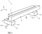
- FIGs 1 to 3 show schematically a first embodiment of a cooling beam 1 for cooling a rolling stock 5 moved in a transport direction 3 (see Figure 12 ).
- Figure 1 a perspective view of the cooling beam 1
- Figure 2 shows a sectional view of the chilled beam 1
- Figure 3 shows a view from below of the cooling beam 1.
- the transport direction 3 defines in the figures a Y direction of a Cartesian coordinate system with coordinates X, Y, Z, whose Z axis runs vertically upwards, ie opposite to the direction of gravity.
- the cooling beam 1 extends transversely to the transport direction 3 in the X direction across the width of the rolled material 5.
- the cooling beam 1 comprises a spray chamber 7, a distribution chamber 9, several full-jet nozzles 11 and two optional coolant discharge devices 12.
- the spray chamber 7 and the distribution chamber 9 are each designed as a hollow space with a longitudinal axis running transversely to the transport direction 3 in the X direction.
- the distribution chamber 9 has a substantially rectangular cross-section in a plane perpendicular to its longitudinal axis.
- the spray chamber 7 has a cross-section in a plane perpendicular to its longitudinal axis that essentially has the shape of the Greek capital letter gamma, with the horizontal section of the gamma running above the distribution chamber 9.
- the spray chamber 7 and the distribution chamber 9 are connected to each other by several passage openings 13.
- the passage openings 13 are arranged one behind the other transversely to the transport direction 3 in the X direction. an upper side of the distribution chamber 9.
- the distribution chamber 9 can be filled with a coolant, for example with cooling water, from the outside via a coolant inlet (not shown).
- the spray chamber 7 can be filled with the coolant from the distribution chamber 9 via the passage openings 13.
- each full-jet nozzle 11 a coolant jet of the coolant with an almost constant jet diameter can be output from the spray chamber 7 from an output side 17 of the cooling beam 1 in an output direction 15 to the rolling stock 5.
- the output direction 15 in this case is the direction of gravity, i.e. opposite to the Z direction.
- the output side 17 in this case is the underside of the cooling beam 1.
- Each full-jet nozzle 11 has a tubular nozzle body 19 with a vertical longitudinal axis, i.e. parallel to the Z axis.
- the nozzle body 19 runs within the spray chamber 7 from a bottom of the spray chamber 7 to an open end 21 of the nozzle body 19, which is arranged in an upper region of the spray chamber 7 above the height of the top of the distribution chamber 9 and through which coolant from the spray chamber 7 can be fed into the full-jet nozzle 11.
- the nozzle bodies 19 are, for example, hollow-cylindrical or taper conically from their open end 21 to the bottom of the spray chamber 7.
- the full-jet nozzles 11 each have an outlet opening 22, the outlet diameter D of which is between 3 mm and 12 mm.
- This design of the cooling beam 1 has the advantageous effect that, in the event of an interruption in the cooling of the rolling stock 5 after the interruption of the coolant supply to the distribution chamber 9, coolant can only flow to the rolling stock 5 from the area of the spray chamber 7 located above the open ends 21 of the nozzle bodies 19 and from the nozzle bodies 19 themselves, while the remaining volume of the spray chamber 7 and the distribution chamber 9 remain filled with coolant.
- the cooling beam 1 further has a nozzle density of the full jet nozzles 11 that varies transversely to the transport direction 3, wherein the nozzle density is maximum in a central region of the cooling beam 1 and decreases transversely to the transport direction 3 towards the edge regions of the cooling beam 1 (see Figure 3 ).
- the full-jet nozzles 11 are arranged in three rows of nozzles 23 to 25 running transversely to the transport direction 3, wherein the full-jet nozzles 11 of different rows of nozzles 23 to 25 are arranged offset from one another in the transport direction 3.
- the variation in the nozzle density transversely to the transport direction 3 is achieved by varying a nozzle spacing d of adjacent full-jet nozzles 11 of each row of nozzles 23 to 25, wherein the nozzle spacing d is minimal in the middle region of the cooling beam 1 and increases transversely to the transport direction 3 towards the edge regions of the cooling beam 1.
- the nozzle spacing d increases parabolically from the middle region to each edge region of the cooling beam 1. This advantageously makes it possible to reduce temperature differences in the rolling stock 5 when the temperature of the rolling stock 5 decreases from a middle region of the rolling stock 5 to the edge regions of the rolling stock 5.
- the nozzle distance d varies, for example, between 25 mm and 70 mm.
- the optional coolant drainage devices 12 are each arranged under an edge region of the spray chamber 7 and are designed to collect and drain coolant that is emitted by full-jet nozzles 11 arranged in the respective edge region of the spray chamber 7 (so-called edge masking) so that the coolant does not reach the corresponding edge region of the rolling stock 5 and cool the edge region of the rolling stock 5 too much.
- each coolant drainage device 12 has a coolant collecting container 12.1 and a coolant drainage pipe 12.2.
- the coolant drainage pipe 12.2 is arranged on an underside of the coolant collecting container 12.1 and serves to drain coolant collected in the coolant collecting container 12.1.
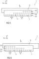
- the Figures 4 to 7 each show a further embodiment of a cooling beam 1 in a bottom view of the respective cooling beam 1.
- the cooling beam 1 of each of these embodiments differs from the one shown in the Figures 1 to 3
- the cooling beam 1 shown in the drawing is only characterized by the distribution of the full jet nozzles 11 transverse to the transport direction 3.
- the full-jet nozzles 11 are arranged in three rows of nozzles 23 to 25 running transversely to the transport direction 3, wherein the full-jet nozzles 11 of different rows of nozzles 23 to 25 are arranged offset from one another in the transport direction 3.
- Figure 4 shows a cooling beam 1 in which the nozzle spacing d of adjacent full-jet nozzles 11 of each nozzle row 23 to 25 decreases from the middle region of the cooling beam 1 transversely to the transport direction 3 to the edge regions of the cooling beam 1 (for example parabolically), so that the nozzle density of the full-jet nozzles 11 increases from the middle region of the cooling beam 1 to the edge regions of the cooling beam 1.
- This advantageously reduces temperature differences of the rolling stock 5 when the temperature of the rolling stock 5 increases from a middle region of the rolling stock 5 to the edge regions of the rolling stock 5.
- Figure 5 shows a cooling beam 1 in which the nozzle spacing d of adjacent full jet nozzles 11 of all nozzle rows 23 to 25 is the same, but the nozzle rows 23 to 25 are spaced at different distances from one in Figure 5 right-hand edge region of the cooling beam 1 to the left, so that the nozzle density in the right-hand edge region has a nozzle density maximum.
- This advantageously reduces temperature differences of the rolling stock 5 when the temperature of the rolling stock 5 from the right-hand edge region of the rolling stock 5 to the left-hand edge area of the rolling stock 5 decreases.
- Figure 6 shows a cooling beam 1 in which the nozzle spacing d of adjacent full jet nozzles 11 of all nozzle rows 23 to 25 is also the same, but the nozzle rows 23 to 25 are spaced at different distances from one in Figure 6 left-hand edge region of the cooling beam 1 to the right, so that the nozzle density in the left-hand edge region has a nozzle density maximum.
- Temperature differences of the rolling stock 5 can thereby advantageously be reduced if the temperature of the rolling stock 5 decreases from the left-hand edge region of the rolling stock 5 to the right-hand edge region of the rolling stock 5.
- Figure 7 shows a cooling beam 1 in which the nozzle spacing d of adjacent full-jet nozzles 11 of all nozzle rows 23 to 25 is the same and the nozzle density is also constant transversely to the transport direction 3. Such a cooling beam 1 therefore causes uniform cooling of the rolling stock 5 transversely to the transport direction 3.
- Figure 8 shows a cooling beam 1, which differs from the one in Figure 7 shown cooling beam 1 only in that the outlet diameter D of the full jet nozzles 11 varies transversely to the transport direction 3.
- the outlet diameter D is maximum in the middle region of the cooling beam 1 and decreases transversely to the transport direction 3 towards the edge regions of the cooling beam 1, whereby the decrease can be parabolic, for example.
- cooling beams 1 shown can be modified in various ways.
- the distributor chamber 9 can be omitted in each case, with the spray chamber 7 being filled with coolant directly instead of via the distributor chamber 9.
- the full-jet nozzles 11 can extend less far or not at all into the spray chamber 7, ie the nozzle bodies 19 can be made shorter or can be omitted entirely.
- the full-jet nozzles 11 can be arranged in a number of nozzle rows 23 to 25 other than three.
- the embodiment shown can also be modified in such a way that the outlet diameter D of the full jet nozzles 11 transverse to the transport direction 3 is different from the embodiment shown in Figure 8 shown cooling beam 1.
- the outlet diameter D can be minimal in the middle region of the cooling beam 1 and increase transversely to the transport direction 3 towards the edge regions of the cooling beam 1, or the outlet diameter D can be maximal in an edge region of the cooling beam 1 and decrease transversely to the transport direction 3 towards the edge region opposite this edge region.
- Figure 9 shows schematically from the Figures 1 to 8 Volume flows V 1 to V 5 of a coolant emitted by the cooling beam shown as a function of a position transverse to the transport direction 3.
- a first volume flow V 1 is generated by the Figures 3 and 8 shown cooling beam 1 and decreases from a central region of the cooling beam 1 towards the edge regions, with the decrease being, for example, parabolic.
- a second volume flow V 2 is supplied from the Figure 4 shown cooling beam 1 and increases from a central region of the cooling beam 1 towards the edge regions, with the increase being, for example, parabolic.
- a third volume flow V 3 is supplied by the Figure 5 shown cooling beam 1 and decreases from a first edge region to the second edge region of the cooling beam 1.
- a fourth volume flow V 4 is supplied by the Figure 6 shown cooling beam 1 and decreases from the second edge region to the first edge region of the cooling beam 1.
- a fifth volume flow V 5 is supplied by the Figure 7 shown cooling beam 1 and is constant transversely to the transport direction 3.
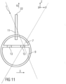
- FIG 10 shows a sectional view of a further embodiment of a cooling beam 1.
- the distribution chamber 9 is arranged below the spray chamber 7.
- the spray chamber 7 and the distribution chamber 9 are connected to one another by several passage openings 13 and the cooling beam 1 has several full-jet nozzles 11, each of which has a tubular nozzle body 19 with a cylinder axis running vertically, i.e. parallel to the Z axis.
- the nozzle bodies 19 each run from a bottom of the distribution chamber 9 through the distribution chamber 9 into the spray chamber 7, where they each have an open end 21 through which coolant from the spray chamber 7 can be fed into the full-jet nozzle 11.
- the full-jet nozzles 11 again have a nozzle density that varies transversely to the transport direction 3 and can, for example, be analogous to any of the nozzles shown in the Figures 1 to 6 shown embodiments can be arranged distributed.
- Figure 12 shows schematically a rolling mill 27 for hot rolling a rolling stock 5, which is transported in a transport direction 3 through the rolling mill 27.
- the rolling mill 27 comprises a finishing mill 29 and a cooling section 31.
- several rolling stands 33 are arranged one behind the other, with which the rolling stock 5 is formed.
- Two rolling stands 33 are shown as an example; however, the finishing train 29 can also have a different number of rolling stands 33.
- the cooling section 31 is connected to the finishing train 29 and has a cooling device 35 for cooling the rolling stock 5.
- the cooling device 35 comprises several cooling beams 1, a temperature measuring device 37 and a control device 39.
- Each cooling beam 1 has several full jet nozzles 11, through which a coolant jet of a coolant with an almost constant jet diameter can be emitted to the rolling stock 5.
- Some cooling beams 1 are arranged one behind the other above the rolling stock 5 and emit coolant jets downwards onto an upper side of the rolling stock 5.
- the other cooling beams 1 are arranged one behind the other below the rolling stock 5 and emit coolant jets upwards onto an underside of the rolling stock 5.
- Figure 12 By way of example, five cooling beams 1 arranged above and five below the rolling stock 5 are shown; however, the cooling device 35 can also have other numbers of cooling beams 1 arranged above and/or below the rolling stock 5.
- the remaining cooling beams 1 have a constant nozzle density as in Figure 7 shown embodiment.
- the cooling beams 1 with varying nozzle densities and/or varying outlet diameters D are preferably arranged (with respect to the transport direction 3) in front of the cooling beams 1 with constant nozzle densities. This ensures that at the beginning of the cooling section 31, where the temperature of the rolling stock 5 is still very high, local temperature differences transverse to the transport direction 3 can be reduced by cooling beams 1 with nozzle densities varying transverse to the transport direction 3, while subsequent cooling beams 1 with constant nozzle densities only reduce the overall temperature of the rolling stock 5, which is uniformly tempered transversely to the transport direction 3.
- the first four cooling beams 1 arranged above the rolling stock 5 and the first four cooling beams 1 arranged below the rolling stock 5 each comprise a cooling beam 1 with a nozzle density which is analogous to Figure 3 from a central region of the chilled beam 1 to the edge regions of the chilled beam 1, a chilled beam 1 with a nozzle density which is analogous to Figure 4 from a central region of the chilled beam 1 to the edge regions of the chilled beam 1, a chilled beam 1 with a nozzle density which is analogous to Figure 5 from one (in Figure 5 right) first edge area of the chilled beam 1 to the (in Figure 5 left) second edge area of the cooling beam 1, and a cooling beam 1 with a nozzle density that is analogous to Figure 6 from the first edge region of the chilled beam 1 to the second edge region of the chilled beam 1.
- cooling beams 1 arranged above the rolling stock 5 preferably each have full jet nozzles 11 and/or a spray chamber 7 and a distribution chamber 9 as in the Figures 1 and 2 shown cooling beams 1 in order to reduce the flow of coolant from these cooling beams 1 onto the rolling stock 5 in the event of an interruption in the coolant supply to the cooling beams 1.
- the cooling beams 1 arranged beneath the rolling stock 5 can be of a simpler design, ie these cooling beams 1 can have simply designed full-jet nozzles 11 without elongated nozzle bodies 19 and/or can not be divided into a spray chamber 7 and a distribution chamber 9, since no coolant can flow onto the rolling stock 5 from the cooling beams 1 arranged beneath the rolling stock 5 in the event of an interruption in the coolant supply to the cooling beams 1.
- the temperature measuring device 37 is preferably as in Figure 12 shown arranged in front of the cooling beam 1 of the cooling device 35.
- a further temperature measuring device 37 can be arranged behind a cooling beam 1 of the cooling device 35.
- the temperature measuring device 37 is designed to determine a temperature distribution of a temperature of the rolling stock 5 transversely to the transport direction 3.
- the temperature measuring device 37 has an infrared scanner for temperature detection with an accuracy of preferably ⁇ 2°C.
- the control device 39 is designed to control flow rates of coolant to the individual cooling beams 1 depending on the temperature distribution of the temperature of the rolling stock 5 transverse to the transport direction 3 determined by the temperature measuring device 37.
- the control device 39 comprises a control unit 47, two coolant pumps 49 and a control valve 51 for each cooling beam 1.
- the flow rate of coolant to one of the cooling beams 1 can be adjusted by each control valve 51.
- the control valves 51 of the cooling beams 1 arranged above the rolling stock 5 are connected to one of the two coolant pumps 49, the control valves 51 of the cooling beams 1 arranged below the rolling stock 5 are connected to the other coolant pump 49.
- a different number of coolant pumps 49 can also be provided, for example only one coolant pump 49 that is connected to all control valves 51, or more than two coolant pumps 49, each connected to only one control valve 51 or with a subset of the control valves 51.
- an elevated tank filled with coolant can also be provided, which is arranged at a suitable height above the control valves 51 and through which the control valves 51 are supplied with coolant.
- coolant pumps 49 or an elevated tank can even be dispensed with entirely. Since the cooling beams 1 each have full-jet nozzles 11, it is generally sufficient to supply the cooling beams 1 with a coolant pressure of approximately 4 bar.
- a typical flow rate of coolant of a cooling beam 1 is approximately 175 m 3 /h.
- the measurement signals recorded by the temperature measuring device 37 are fed to the control unit 47.
- the coolant pumps 49 and control valves 51 can be controlled by the control unit 47.
- the control unit 47 calculates the flow rates of coolant to the individual cooling beams 1 - in particular to those with varying nozzle densities - depending on the temperature distribution recorded by the temperature measuring device 37 and sets them by controlling the control valves 51 in order to compensate for temperature differences in the temperature of the rolling stock 5 transversely to the transport direction 3 by using and a suitable combination of the cooling beams 1 with varying nozzle densities and to reduce the temperature of the rolling stock 5 overall to a desired value, for example a reel temperature.
- the flow rates of coolant to the individual cooling beams 1 are calculated by the control unit 47, for example, using a model of parameters of the rolling stock 5 such as its thickness, temperature and/or heat capacity.
Landscapes
- Engineering & Computer Science (AREA)
- Mechanical Engineering (AREA)
- Metal Rolling (AREA)
- Heat Treatments In General, Especially Conveying And Cooling (AREA)
- Control Of Metal Rolling (AREA)
Claims (5)
- Barre de refroidissement (1) destinée au refroidissement d'un produit de laminage (5) que l'on déplace dans une direction de transport (3), la barre de refroidissement (1) comprenant :- une chambre de pulvérisation (7) qui peut être remplie avec un agent de refroidissement ;- une chambre de distribution (9) destinée au stockage intermédiaire de l'agent de refroidissement, qui est reliée à la chambre de pulvérisation (7) par l'intermédiaire de plusieurs d' ouvertures de passage (13) destinée au remplissage de la chambre de pulvérisation (7) avec un agent de refroidissement à partir de la chambre de distribution (9) ;- dans lequel chaque ouverture de passage (13) est disposée entre la chambre de distribution (9) et la chambre de pulvérisation (7) sur un côté supérieur de la chambre de distribution (9)et les ouvertures de passage (13) qui s'étendent en direction transversale par rapport à la direction de transport (3) sont disposées l'une derrière l'autre au-dessus de la chambre de distribution (9) ;- et plusieurs buses de jets pleins (11) qui peuvent être alimentées à partir de la chambre de pulvérisation (7) avec un agent de refroidissement, par l'intermédiaire desquelles respectivement un jet d'agent de refroidissement d'un agent de refroidissement, possédant un diamètre de jet pratiquement constant, peut être distribué dans une direction de distribution (15) en direction du produit de laminage (5) ;- dans lequel chaque buse de jet plein (11) présente un corps de buse (19) de forme tubulaire qui présente une extrémité ouverte (21) disposée dans une zone supérieure de la barre de refroidissement (1) à l'intérieur de la chambre de pulvérisation (7), destiné à l'alimentation de l'agent de refroidissement dans la buse de jet plein (11) ;- dans lequel l'extrémité ouverte (21) est disposée au-dessus de la hauteur du côté supérieur de la chambre de distribution (9)- et le corps de buse (19), à l'intérieur de la chambre de pulvérisation, passe d'un sol de la chambre de pulvérisation (7) à l'extrémité ouverte (21) du corps de buse (19),- et dans lequel les buses de jets plein (11) possèdent chacune un port de sortie (22) avec un diamètre de sortie(D)entre 3 mm et 12 mm,- et les buses de jets pleins (11) sont disposées en formant plusieurs rangées de buses (23 à 25) s'étendant en direction transversale par rapport à la direction de transport (3) et en ce que les buses de jets pleins (11) de différentes rangées de buses (23 à 25) sont disposées en décalage réciproque dans la direction de transport (3).
- Barre de refroidissement (1) selon la revendication 1, caractérisée en ce qu'une masse volumique de buse des buses de jets pleins (11) varie en direction transversale par rapport à la direction de transport (3).
- Barre de refroidissement (1) selon l'une quelconque des revendications précédentes, caractérisée en ce qu'un diamètre de sortie (D) des buses de jets pleins (11) varie en direction transversale par rapport à la direction de transport (3).
- Barre de refroidissement (1) selon l'une des revendications précédentes, caractérisée en ce qu'une distance de buse (d) entre des buses de jets pleins (11) respectivement voisines, de chaque rangée de buses (23 à 25), varie.
- Barre de refroidissement (1) selon l'une quelconque des revendications précédentes, caractérisée par au moins un dispositif d'évacuation de l'agent de refroidissement (12) destiné à l'évacuation de l'agent de refroidissement qui est distribué à partir de buses de jets pleins (11) disposées dans une zone marginale de la chambre de pulvérisation (7).
Priority Applications (7)
| Application Number | Priority Date | Filing Date | Title |
|---|---|---|---|
| EP17168241.2A EP3395463B2 (fr) | 2017-04-26 | 2017-04-26 | Refroidissement d'un laminé |
| CN201880027555.1A CN110536761B (zh) | 2017-04-26 | 2018-03-14 | 被轧制材料的冷却 |
| PCT/EP2018/056437 WO2018197100A2 (fr) | 2017-04-26 | 2018-03-14 | Refroidissement d'un produit laminé |
| EP18719050.9A EP3615237A2 (fr) | 2017-04-26 | 2018-03-14 | Refroidissement d'un produit laminé |
| US16/607,399 US11358195B2 (en) | 2017-04-26 | 2018-03-14 | Cooling of rolled matertial |
| JP2019555876A JP6946458B2 (ja) | 2017-04-26 | 2018-03-14 | 被圧延材料の冷却 |
| US17/716,000 US11786949B2 (en) | 2017-04-26 | 2022-04-08 | Cooling of rolled material |
Applications Claiming Priority (1)
| Application Number | Priority Date | Filing Date | Title |
|---|---|---|---|
| EP17168241.2A EP3395463B2 (fr) | 2017-04-26 | 2017-04-26 | Refroidissement d'un laminé |
Publications (3)
| Publication Number | Publication Date |
|---|---|
| EP3395463A1 EP3395463A1 (fr) | 2018-10-31 |
| EP3395463B1 EP3395463B1 (fr) | 2019-12-25 |
| EP3395463B2 true EP3395463B2 (fr) | 2024-10-30 |
Family
ID=58632897
Family Applications (2)
| Application Number | Title | Priority Date | Filing Date |
|---|---|---|---|
| EP17168241.2A Active EP3395463B2 (fr) | 2017-04-26 | 2017-04-26 | Refroidissement d'un laminé |
| EP18719050.9A Withdrawn EP3615237A2 (fr) | 2017-04-26 | 2018-03-14 | Refroidissement d'un produit laminé |
Family Applications After (1)
| Application Number | Title | Priority Date | Filing Date |
|---|---|---|---|
| EP18719050.9A Withdrawn EP3615237A2 (fr) | 2017-04-26 | 2018-03-14 | Refroidissement d'un produit laminé |
Country Status (5)
| Country | Link |
|---|---|
| US (2) | US11358195B2 (fr) |
| EP (2) | EP3395463B2 (fr) |
| JP (1) | JP6946458B2 (fr) |
| CN (1) | CN110536761B (fr) |
| WO (1) | WO2018197100A2 (fr) |
Families Citing this family (7)
| Publication number | Priority date | Publication date | Assignee | Title |
|---|---|---|---|---|
| DE102018211177A1 (de) * | 2018-04-13 | 2019-10-17 | Sms Group Gmbh | Kühleinrichtung zum Kühlen eines metallischen Gutes sowie Verfahren zu deren Herstellung und Betrieb |
| EP3670682A1 (fr) | 2018-12-20 | 2020-06-24 | Primetals Technologies Austria GmbH | Fabrication d'une bande métallique à une structure mixte de martensite-austénite |
| EP3808466A1 (fr) * | 2019-10-16 | 2021-04-21 | Primetals Technologies Germany GmbH | Dispositif de refroidissement à rayonnement de refroidissement pourvu de section transversale creuse |
| EP3895819B1 (fr) * | 2020-04-14 | 2023-06-07 | Primetals Technologies Germany GmbH | Fonctionnement d'un dispositif de refrodissement avec une pression de fonctionnement minimale |
| DE102020205252A1 (de) | 2020-04-24 | 2021-10-28 | Kocks Technik Gmbh & Co Kg | Vorrichtung zum Kühlen von Langprodukten und Verfahren zum Kühlen eines Langproduktes unter Verwendung derselben |
| EP4124398B1 (fr) * | 2021-07-27 | 2024-04-10 | Primetals Technologies Austria GmbH | Procédé de détermination des propriétés mécaniques d'un produit laminé a l'aide d'un modèle hybride |
| CN115532855B (zh) * | 2022-10-10 | 2024-01-09 | 江苏东方成套设备制造集团有限公司 | 一种连续穿水冷却装置 |
Citations (2)
| Publication number | Priority date | Publication date | Assignee | Title |
|---|---|---|---|---|
| EP0099213A1 (fr) † | 1982-07-07 | 1984-01-25 | Kawasaki Steel Corporation | Distributeur à filières pour le refroidissement de plaques |
| DE4009868A1 (de) † | 1990-03-28 | 1991-10-02 | Schloemann Siemag Ag | Vorrichtung zum kuehlen von walzband |
Family Cites Families (32)
| Publication number | Priority date | Publication date | Assignee | Title |
|---|---|---|---|---|
| SU908848A1 (ru) * | 1980-02-11 | 1982-02-28 | Донецкий научно-исследовательский институт черной металлургии | Устройство дл охлаждени проката |
| JPS5832511A (ja) * | 1981-08-21 | 1983-02-25 | Nippon Kokan Kk <Nkk> | 厚鋼板の冷却方法 |
| JPS5890313A (ja) | 1981-11-20 | 1983-05-30 | Nippon Steel Corp | 鋼板の冷却装置 |
| JPS59137111A (ja) * | 1983-01-28 | 1984-08-07 | Nippon Steel Corp | 熱鋼板冷却装置 |
| SU1296599A1 (ru) * | 1985-03-18 | 1987-03-15 | Всесоюзный научно-исследовательский институт металлургической теплотехники | Устройство дл охлаждени проката |
| JPS621789A (ja) | 1985-06-27 | 1987-01-07 | ライオン株式会社 | 洗浄剤組成物 |
| JPS6293010A (ja) | 1985-10-17 | 1987-04-28 | Kobe Steel Ltd | 熱間圧延鋼板の製造方法 |
| JPS63111209U (fr) | 1987-01-09 | 1988-07-16 | ||
| JPH01178309A (ja) * | 1987-12-29 | 1989-07-14 | Nippon Steel Corp | 熱延鋼板の冷却装置 |
| JP2564400Y2 (ja) | 1991-10-23 | 1998-03-09 | 三菱重工業株式会社 | ラミナフロー冷却装置 |
| JPH05305328A (ja) * | 1992-04-30 | 1993-11-19 | Kawasaki Steel Corp | フランジ水冷によるh形鋼の温度制御方法 |
| JP3157635B2 (ja) * | 1993-01-20 | 2001-04-16 | 川崎製鉄株式会社 | 高温金属板の下面冷却装置 |
| US6062056A (en) * | 1998-02-18 | 2000-05-16 | Tippins Incorporated | Method and apparatus for cooling a steel strip |
| DE19850253A1 (de) | 1998-10-31 | 2000-05-04 | Schloemann Siemag Ag | Verfahren und System zur Regelung von Kühlstrecken |
| DE19854675C2 (de) | 1998-11-26 | 2002-09-26 | Thyssenkrupp Stahl Ag | Vorrichtung zum Kühlen eines Metallbandes, insbesondere eies Warmbreitbandes |
| DE19934557C2 (de) | 1999-07-22 | 2002-10-24 | Thyssenkrupp Stahl Ag | Vorrichtung zum Kühlen von auf einer Förderstrecke geförderten Metallbändern oder -blechen |
| JP3613133B2 (ja) * | 2000-05-09 | 2005-01-26 | Jfeスチール株式会社 | 熱延鋼帯の冷却装置 |
| DE10207584A1 (de) * | 2002-02-22 | 2003-09-11 | Vits Maschb Gmbh I Ins | Verfahren zum Abkühlen von Bändern oder Platten aus Metall und Kühlvorrichtung |
| US7523631B2 (en) * | 2002-08-08 | 2009-04-28 | Jfe Steel Corporation | Cooling device, manufacturing method, and manufacturing line for hot rolled steel band |
| AT414102B (de) * | 2004-08-04 | 2006-09-15 | Ebner Ind Ofenbau | Vorrichtung zum kühlen eines blechbandes |
| US7181822B2 (en) | 2005-01-20 | 2007-02-27 | Nucor Corporation | Method and apparatus for controlling strip shape in hot rolling mills |
| EP1938911A1 (fr) * | 2006-12-27 | 2008-07-02 | VAI Industries (UK) Ltd. | Dispositif et procédé pour refroidissement contrôlé |
| JP5191683B2 (ja) | 2007-04-16 | 2013-05-08 | 新日鐵住金株式会社 | 冷却装置 |
| DE102007053523A1 (de) * | 2007-05-30 | 2008-12-04 | Sms Demag Ag | Vorrichtung zur Beeinflussung der Temperaturverteilung über der Breite |
| CN100495411C (zh) * | 2007-12-18 | 2009-06-03 | 东北大学 | 一种预测热轧过程板带温度场的有限元方法 |
| CN101456038B (zh) * | 2009-01-08 | 2012-01-04 | 上海交通大学 | 热轧带钢层流冷却过程板带温度监测方法 |
| JP5581755B2 (ja) * | 2010-03-18 | 2014-09-03 | Jfeスチール株式会社 | 鋼材の冷却装置および冷却方法 |
| WO2012126107A1 (fr) * | 2011-03-18 | 2012-09-27 | Novelis Inc. | Procédé et équipement pour éliminer le liquide de refroidissement d'un feuillard en mouvement |
| KR101370506B1 (ko) * | 2012-07-06 | 2014-03-06 | 주식회사 포스코 | 열가공 제어 공정의 가속냉각 장치 |
| DE102012223848A1 (de) * | 2012-12-19 | 2014-06-26 | Sms Siemag Ag | Vorrichtung und Verfahren zum Kühlen von Walzgut |
| EP2792428A1 (fr) | 2013-04-15 | 2014-10-22 | Siemens VAI Metals Technologies GmbH | Dispositif de refroidissement avec effet de refroidissement dépendant de la largeur |
| WO2017111243A1 (fr) * | 2015-12-23 | 2017-06-29 | 주식회사 포스코 | Système de redressage et procédé de redressage |
-
2017
- 2017-04-26 EP EP17168241.2A patent/EP3395463B2/fr active Active
-
2018
- 2018-03-14 WO PCT/EP2018/056437 patent/WO2018197100A2/fr not_active Ceased
- 2018-03-14 CN CN201880027555.1A patent/CN110536761B/zh active Active
- 2018-03-14 US US16/607,399 patent/US11358195B2/en active Active
- 2018-03-14 JP JP2019555876A patent/JP6946458B2/ja active Active
- 2018-03-14 EP EP18719050.9A patent/EP3615237A2/fr not_active Withdrawn
-
2022
- 2022-04-08 US US17/716,000 patent/US11786949B2/en active Active
Patent Citations (2)
| Publication number | Priority date | Publication date | Assignee | Title |
|---|---|---|---|---|
| EP0099213A1 (fr) † | 1982-07-07 | 1984-01-25 | Kawasaki Steel Corporation | Distributeur à filières pour le refroidissement de plaques |
| DE4009868A1 (de) † | 1990-03-28 | 1991-10-02 | Schloemann Siemag Ag | Vorrichtung zum kuehlen von walzband |
Also Published As
| Publication number | Publication date |
|---|---|
| US11786949B2 (en) | 2023-10-17 |
| US20200047230A1 (en) | 2020-02-13 |
| EP3395463B1 (fr) | 2019-12-25 |
| WO2018197100A2 (fr) | 2018-11-01 |
| EP3395463A1 (fr) | 2018-10-31 |
| JP2020517458A (ja) | 2020-06-18 |
| US11358195B2 (en) | 2022-06-14 |
| EP3615237A2 (fr) | 2020-03-04 |
| CN110536761B (zh) | 2022-02-01 |
| JP6946458B2 (ja) | 2021-10-06 |
| WO2018197100A3 (fr) | 2018-12-27 |
| US20220226873A1 (en) | 2022-07-21 |
| CN110536761A (zh) | 2019-12-03 |
Similar Documents
| Publication | Publication Date | Title |
|---|---|---|
| EP3395463B2 (fr) | Refroidissement d'un laminé | |
| EP2162246B1 (fr) | Dispositif de refroidissement pour le refroidissement d'un feuillard métallique | |
| EP3308868B1 (fr) | Refroidissement d'un rouleau d'une cage de laminoir | |
| DE102007010375A1 (de) | Vorrichtung zur Kühlung eines Metallbandes | |
| DE60224211T2 (de) | Verfahren und vorrichtung zur kühlung von stahlplatten | |
| EP2310152B1 (fr) | Procédé permettant le guidage longitudinal d'un produit laminé, en particulier d'une bande d'acier laminée à chaud, et laminoir à chaud pour la mise en oeuvre de ce procédé | |
| EP2344287B1 (fr) | Procédé et dispositif pour le refroidissement d'une bande préliminaire ou d'une bande d'une ligne continue métallique dans un laminoir à chaud | |
| EP1900449B1 (fr) | Poutre de pulvérisation d'une installation de décalaminage hydraulique et procédé de fonctionnement d'une telle poutre de pulvérisation | |
| EP3612651B1 (fr) | Dispositif de refroidissement des bandes ou tôles métalliques | |
| DE3435501C2 (de) | Vorrichtung zum kontinuierlichen Kühlen einer erwärmten, waagerecht liegenden Metallplatte | |
| WO2015075041A1 (fr) | Procédé de traitement thermique et dispositif de trempe pour refroidir une tôle métallique en forme de plaque ou de bande | |
| DE3537508C2 (fr) | ||
| EP3606682B1 (fr) | Décalamineur et procédé de décalaminage chimique d'une bande métallique | |
| WO2019101486A1 (fr) | Barre de refroidissement et processus de refroidissement avec taux de refroidissement variable pour tôles d'acier | |
| EP3941655B1 (fr) | Installation et procédé pour fabriquer un feuillard à chaud métallique | |
| EP0383786B1 (fr) | Procede de production d'un rideau d'eau | |
| EP3774100B1 (fr) | Dispositif de refroidissement servant à refroidir un produit métallique et procédé permettant sa fabrication et son fonctionnement | |
| DE2547416A1 (de) | Vorrichtung zum kuehlen von bandmaterial | |
| EP3983145B1 (fr) | Refroidissement séquentiel de produits larges plats métalliques | |
| EP0001770B1 (fr) | Procédé et dispositif de refroidissement pour brames | |
| DE2143962A1 (en) | Cooling and guiding continuously cast bar - avoiding formation of swellings or holes in the bar at high casting rates | |
| DE2426828A1 (de) | Vorrichtung zum kuehlen von stangenmaterial | |
| DE3533305A1 (de) | Vorrichtung zur regelung der balligkeit der walze in einem walzwerk | |
| DE102016216197A1 (de) | Düsenvorrichtung für ein Kühlmedium | |
| DE3708128A1 (de) | Verfahren und druckkuehlaggregat zum gefuehrten abkuehlen geformten, schweren bis leichten, heissen, durchlaufenden produktionsguts aus stahl und metall in druckwasser |
Legal Events
| Date | Code | Title | Description |
|---|---|---|---|
| PUAI | Public reference made under article 153(3) epc to a published international application that has entered the european phase |
Free format text: ORIGINAL CODE: 0009012 |
|
| STAA | Information on the status of an ep patent application or granted ep patent |
Free format text: STATUS: THE APPLICATION HAS BEEN PUBLISHED |
|
| AK | Designated contracting states |
Kind code of ref document: A1 Designated state(s): AL AT BE BG CH CY CZ DE DK EE ES FI FR GB GR HR HU IE IS IT LI LT LU LV MC MK MT NL NO PL PT RO RS SE SI SK SM TR |
|
| AX | Request for extension of the european patent |
Extension state: BA ME |
|
| STAA | Information on the status of an ep patent application or granted ep patent |
Free format text: STATUS: REQUEST FOR EXAMINATION WAS MADE |
|
| 17P | Request for examination filed |
Effective date: 20190430 |
|
| RBV | Designated contracting states (corrected) |
Designated state(s): AL AT BE BG CH CY CZ DE DK EE ES FI FR GB GR HR HU IE IS IT LI LT LU LV MC MK MT NL NO PL PT RO RS SE SI SK SM TR |
|
| GRAP | Despatch of communication of intention to grant a patent |
Free format text: ORIGINAL CODE: EPIDOSNIGR1 |
|
| STAA | Information on the status of an ep patent application or granted ep patent |
Free format text: STATUS: GRANT OF PATENT IS INTENDED |
|
| INTG | Intention to grant announced |
Effective date: 20190819 |
|
| GRAS | Grant fee paid |
Free format text: ORIGINAL CODE: EPIDOSNIGR3 |
|
| GRAA | (expected) grant |
Free format text: ORIGINAL CODE: 0009210 |
|
| STAA | Information on the status of an ep patent application or granted ep patent |
Free format text: STATUS: THE PATENT HAS BEEN GRANTED |
|
| AK | Designated contracting states |
Kind code of ref document: B1 Designated state(s): AL AT BE BG CH CY CZ DE DK EE ES FI FR GB GR HR HU IE IS IT LI LT LU LV MC MK MT NL NO PL PT RO RS SE SI SK SM TR |
|
| REG | Reference to a national code |
Ref country code: GB Ref legal event code: FG4D Free format text: NOT ENGLISH |
|
| REG | Reference to a national code |
Ref country code: CH Ref legal event code: EP |
|
| REG | Reference to a national code |
Ref country code: AT Ref legal event code: REF Ref document number: 1216594 Country of ref document: AT Kind code of ref document: T Effective date: 20200115 |
|
| REG | Reference to a national code |
Ref country code: DE Ref legal event code: R096 Ref document number: 502017003240 Country of ref document: DE |
|
| REG | Reference to a national code |
Ref country code: IE Ref legal event code: FG4D Free format text: LANGUAGE OF EP DOCUMENT: GERMAN |
|
| REG | Reference to a national code |
Ref country code: NL Ref legal event code: FP |
|
| PG25 | Lapsed in a contracting state [announced via postgrant information from national office to epo] |
Ref country code: LV Free format text: LAPSE BECAUSE OF FAILURE TO SUBMIT A TRANSLATION OF THE DESCRIPTION OR TO PAY THE FEE WITHIN THE PRESCRIBED TIME-LIMIT Effective date: 20191225 Ref country code: SE Free format text: LAPSE BECAUSE OF FAILURE TO SUBMIT A TRANSLATION OF THE DESCRIPTION OR TO PAY THE FEE WITHIN THE PRESCRIBED TIME-LIMIT Effective date: 20191225 Ref country code: LT Free format text: LAPSE BECAUSE OF FAILURE TO SUBMIT A TRANSLATION OF THE DESCRIPTION OR TO PAY THE FEE WITHIN THE PRESCRIBED TIME-LIMIT Effective date: 20191225 Ref country code: GR Free format text: LAPSE BECAUSE OF FAILURE TO SUBMIT A TRANSLATION OF THE DESCRIPTION OR TO PAY THE FEE WITHIN THE PRESCRIBED TIME-LIMIT Effective date: 20200326 Ref country code: NO Free format text: LAPSE BECAUSE OF FAILURE TO SUBMIT A TRANSLATION OF THE DESCRIPTION OR TO PAY THE FEE WITHIN THE PRESCRIBED TIME-LIMIT Effective date: 20200325 Ref country code: BG Free format text: LAPSE BECAUSE OF FAILURE TO SUBMIT A TRANSLATION OF THE DESCRIPTION OR TO PAY THE FEE WITHIN THE PRESCRIBED TIME-LIMIT Effective date: 20200325 Ref country code: FI Free format text: LAPSE BECAUSE OF FAILURE TO SUBMIT A TRANSLATION OF THE DESCRIPTION OR TO PAY THE FEE WITHIN THE PRESCRIBED TIME-LIMIT Effective date: 20191225 |
|
| REG | Reference to a national code |
Ref country code: LT Ref legal event code: MG4D |
|
| PG25 | Lapsed in a contracting state [announced via postgrant information from national office to epo] |
Ref country code: RS Free format text: LAPSE BECAUSE OF FAILURE TO SUBMIT A TRANSLATION OF THE DESCRIPTION OR TO PAY THE FEE WITHIN THE PRESCRIBED TIME-LIMIT Effective date: 20191225 Ref country code: HR Free format text: LAPSE BECAUSE OF FAILURE TO SUBMIT A TRANSLATION OF THE DESCRIPTION OR TO PAY THE FEE WITHIN THE PRESCRIBED TIME-LIMIT Effective date: 20191225 |
|
| PG25 | Lapsed in a contracting state [announced via postgrant information from national office to epo] |
Ref country code: AL Free format text: LAPSE BECAUSE OF FAILURE TO SUBMIT A TRANSLATION OF THE DESCRIPTION OR TO PAY THE FEE WITHIN THE PRESCRIBED TIME-LIMIT Effective date: 20191225 |
|
| PG25 | Lapsed in a contracting state [announced via postgrant information from national office to epo] |
Ref country code: CZ Free format text: LAPSE BECAUSE OF FAILURE TO SUBMIT A TRANSLATION OF THE DESCRIPTION OR TO PAY THE FEE WITHIN THE PRESCRIBED TIME-LIMIT Effective date: 20191225 Ref country code: PT Free format text: LAPSE BECAUSE OF FAILURE TO SUBMIT A TRANSLATION OF THE DESCRIPTION OR TO PAY THE FEE WITHIN THE PRESCRIBED TIME-LIMIT Effective date: 20200520 Ref country code: RO Free format text: LAPSE BECAUSE OF FAILURE TO SUBMIT A TRANSLATION OF THE DESCRIPTION OR TO PAY THE FEE WITHIN THE PRESCRIBED TIME-LIMIT Effective date: 20191225 Ref country code: EE Free format text: LAPSE BECAUSE OF FAILURE TO SUBMIT A TRANSLATION OF THE DESCRIPTION OR TO PAY THE FEE WITHIN THE PRESCRIBED TIME-LIMIT Effective date: 20191225 |
|
| PG25 | Lapsed in a contracting state [announced via postgrant information from national office to epo] |
Ref country code: SK Free format text: LAPSE BECAUSE OF FAILURE TO SUBMIT A TRANSLATION OF THE DESCRIPTION OR TO PAY THE FEE WITHIN THE PRESCRIBED TIME-LIMIT Effective date: 20191225 Ref country code: IS Free format text: LAPSE BECAUSE OF FAILURE TO SUBMIT A TRANSLATION OF THE DESCRIPTION OR TO PAY THE FEE WITHIN THE PRESCRIBED TIME-LIMIT Effective date: 20200425 Ref country code: SM Free format text: LAPSE BECAUSE OF FAILURE TO SUBMIT A TRANSLATION OF THE DESCRIPTION OR TO PAY THE FEE WITHIN THE PRESCRIBED TIME-LIMIT Effective date: 20191225 |
|
| REG | Reference to a national code |
Ref country code: DE Ref legal event code: R026 Ref document number: 502017003240 Country of ref document: DE |
|
| PLBI | Opposition filed |
Free format text: ORIGINAL CODE: 0009260 |
|
| PLAX | Notice of opposition and request to file observation + time limit sent |
Free format text: ORIGINAL CODE: EPIDOSNOBS2 |
|
| 26 | Opposition filed |
Opponent name: SMS GROUP GMBH Effective date: 20200918 |
|
| PG25 | Lapsed in a contracting state [announced via postgrant information from national office to epo] |
Ref country code: ES Free format text: LAPSE BECAUSE OF FAILURE TO SUBMIT A TRANSLATION OF THE DESCRIPTION OR TO PAY THE FEE WITHIN THE PRESCRIBED TIME-LIMIT Effective date: 20191225 Ref country code: DK Free format text: LAPSE BECAUSE OF FAILURE TO SUBMIT A TRANSLATION OF THE DESCRIPTION OR TO PAY THE FEE WITHIN THE PRESCRIBED TIME-LIMIT Effective date: 20191225 |
|
| PG25 | Lapsed in a contracting state [announced via postgrant information from national office to epo] |
Ref country code: MC Free format text: LAPSE BECAUSE OF FAILURE TO SUBMIT A TRANSLATION OF THE DESCRIPTION OR TO PAY THE FEE WITHIN THE PRESCRIBED TIME-LIMIT Effective date: 20191225 Ref country code: SI Free format text: LAPSE BECAUSE OF FAILURE TO SUBMIT A TRANSLATION OF THE DESCRIPTION OR TO PAY THE FEE WITHIN THE PRESCRIBED TIME-LIMIT Effective date: 20191225 |
|
| REG | Reference to a national code |
Ref country code: CH Ref legal event code: PL |
|
| PLAF | Information modified related to communication of a notice of opposition and request to file observations + time limit |
Free format text: ORIGINAL CODE: EPIDOSCOBS2 |
|
| PG25 | Lapsed in a contracting state [announced via postgrant information from national office to epo] |
Ref country code: FR Free format text: LAPSE BECAUSE OF NON-PAYMENT OF DUE FEES Effective date: 20200430 Ref country code: LU Free format text: LAPSE BECAUSE OF NON-PAYMENT OF DUE FEES Effective date: 20200426 Ref country code: LI Free format text: LAPSE BECAUSE OF NON-PAYMENT OF DUE FEES Effective date: 20200430 Ref country code: CH Free format text: LAPSE BECAUSE OF NON-PAYMENT OF DUE FEES Effective date: 20200430 |
|
| PLBB | Reply of patent proprietor to notice(s) of opposition received |
Free format text: ORIGINAL CODE: EPIDOSNOBS3 |
|
| PG25 | Lapsed in a contracting state [announced via postgrant information from national office to epo] |
Ref country code: PL Free format text: LAPSE BECAUSE OF FAILURE TO SUBMIT A TRANSLATION OF THE DESCRIPTION OR TO PAY THE FEE WITHIN THE PRESCRIBED TIME-LIMIT Effective date: 20191225 |
|
| PG25 | Lapsed in a contracting state [announced via postgrant information from national office to epo] |
Ref country code: IE Free format text: LAPSE BECAUSE OF NON-PAYMENT OF DUE FEES Effective date: 20200426 |
|
| RDAF | Communication despatched that patent is revoked |
Free format text: ORIGINAL CODE: EPIDOSNREV1 |
|
| APBM | Appeal reference recorded |
Free format text: ORIGINAL CODE: EPIDOSNREFNO |
|
| APBP | Date of receipt of notice of appeal recorded |
Free format text: ORIGINAL CODE: EPIDOSNNOA2O |
|
| APAH | Appeal reference modified |
Free format text: ORIGINAL CODE: EPIDOSCREFNO |
|
| APBQ | Date of receipt of statement of grounds of appeal recorded |
Free format text: ORIGINAL CODE: EPIDOSNNOA3O |
|
| GBPC | Gb: european patent ceased through non-payment of renewal fee |
Effective date: 20210426 |
|
| PG25 | Lapsed in a contracting state [announced via postgrant information from national office to epo] |
Ref country code: GB Free format text: LAPSE BECAUSE OF NON-PAYMENT OF DUE FEES Effective date: 20210426 |
|
| PG25 | Lapsed in a contracting state [announced via postgrant information from national office to epo] |
Ref country code: TR Free format text: LAPSE BECAUSE OF FAILURE TO SUBMIT A TRANSLATION OF THE DESCRIPTION OR TO PAY THE FEE WITHIN THE PRESCRIBED TIME-LIMIT Effective date: 20191225 Ref country code: MT Free format text: LAPSE BECAUSE OF FAILURE TO SUBMIT A TRANSLATION OF THE DESCRIPTION OR TO PAY THE FEE WITHIN THE PRESCRIBED TIME-LIMIT Effective date: 20191225 Ref country code: CY Free format text: LAPSE BECAUSE OF FAILURE TO SUBMIT A TRANSLATION OF THE DESCRIPTION OR TO PAY THE FEE WITHIN THE PRESCRIBED TIME-LIMIT Effective date: 20191225 |
|
| PG25 | Lapsed in a contracting state [announced via postgrant information from national office to epo] |
Ref country code: MK Free format text: LAPSE BECAUSE OF FAILURE TO SUBMIT A TRANSLATION OF THE DESCRIPTION OR TO PAY THE FEE WITHIN THE PRESCRIBED TIME-LIMIT Effective date: 20191225 |
|
| P01 | Opt-out of the competence of the unified patent court (upc) registered |
Effective date: 20230614 |
|
| APBU | Appeal procedure closed |
Free format text: ORIGINAL CODE: EPIDOSNNOA9O |
|
| PUAH | Patent maintained in amended form |
Free format text: ORIGINAL CODE: 0009272 |
|
| STAA | Information on the status of an ep patent application or granted ep patent |
Free format text: STATUS: PATENT MAINTAINED AS AMENDED |
|
| 27A | Patent maintained in amended form |
Effective date: 20241030 |
|
| AK | Designated contracting states |
Kind code of ref document: B2 Designated state(s): AL AT BE BG CH CY CZ DE DK EE ES FI FR GB GR HR HU IE IS IT LI LT LU LV MC MK MT NL NO PL PT RO RS SE SI SK SM TR |
|
| REG | Reference to a national code |
Ref country code: DE Ref legal event code: R102 Ref document number: 502017003240 Country of ref document: DE |
|
| REG | Reference to a national code |
Ref country code: NL Ref legal event code: FP |
|
| PGFP | Annual fee paid to national office [announced via postgrant information from national office to epo] |
Ref country code: NL Payment date: 20250418 Year of fee payment: 9 |
|
| PGFP | Annual fee paid to national office [announced via postgrant information from national office to epo] |
Ref country code: DE Payment date: 20250422 Year of fee payment: 9 |
|
| PGFP | Annual fee paid to national office [announced via postgrant information from national office to epo] |
Ref country code: BE Payment date: 20250418 Year of fee payment: 9 Ref country code: IT Payment date: 20250424 Year of fee payment: 9 |
|
| REG | Reference to a national code |
Ref country code: DE Ref legal event code: R082 Ref document number: 502017003240 Country of ref document: DE Representative=s name: LINDNER BLAUMEIER, PATENT- UND RECHTSANWAELTE,, DE |
|
| PGFP | Annual fee paid to national office [announced via postgrant information from national office to epo] |
Ref country code: AT Payment date: 20250423 Year of fee payment: 9 |