EP3393894B1 - Vorrichtung zur verbesserung der traktion eines kettenfahrzeuges - Google Patents
Vorrichtung zur verbesserung der traktion eines kettenfahrzeuges Download PDFInfo
- Publication number
- EP3393894B1 EP3393894B1 EP16879456.8A EP16879456A EP3393894B1 EP 3393894 B1 EP3393894 B1 EP 3393894B1 EP 16879456 A EP16879456 A EP 16879456A EP 3393894 B1 EP3393894 B1 EP 3393894B1
- Authority
- EP
- European Patent Office
- Prior art keywords
- bracket
- elongate body
- track
- ground engaging
- engaging feature
- Prior art date
- Legal status (The legal status is an assumption and is not a legal conclusion. Google has not performed a legal analysis and makes no representation as to the accuracy of the status listed.)
- Active
Links
- 230000001154 acute effect Effects 0.000 claims description 3
- 229910000831 Steel Inorganic materials 0.000 description 5
- 239000010959 steel Substances 0.000 description 5
- 238000010276 construction Methods 0.000 description 4
- 238000003466 welding Methods 0.000 description 4
- 229910001209 Low-carbon steel Inorganic materials 0.000 description 1
- 238000010521 absorption reaction Methods 0.000 description 1
- 238000004140 cleaning Methods 0.000 description 1
- 239000000463 material Substances 0.000 description 1
- 239000007769 metal material Substances 0.000 description 1
- 230000004048 modification Effects 0.000 description 1
- 238000012986 modification Methods 0.000 description 1
- 230000035939 shock Effects 0.000 description 1
- 125000006850 spacer group Chemical group 0.000 description 1
- XLYOFNOQVPJJNP-UHFFFAOYSA-N water Substances O XLYOFNOQVPJJNP-UHFFFAOYSA-N 0.000 description 1
Images


Classifications
-
- B—PERFORMING OPERATIONS; TRANSPORTING
- B62—LAND VEHICLES FOR TRAVELLING OTHERWISE THAN ON RAILS
- B62D—MOTOR VEHICLES; TRAILERS
- B62D55/00—Endless track vehicles
- B62D55/08—Endless track units; Parts thereof
- B62D55/18—Tracks
- B62D55/26—Ground engaging parts or elements
- B62D55/28—Ground engaging parts or elements detachable
- B62D55/286—For soft grounds, e.g. consisting of snow or swamp
Definitions
- This invention relates to a device for use with a continuous track of a tracked vehicle to enhance the traction of the vehicle.
- Continuous tracks are often used on off-road vehicles to provide ground contact and traction for large vehicles.
- Standard continuous tracks are formed from a number of rigid track shoes that are joined to each other by hinges. Each track shoe typically has one or more ribs extending along the shoe to provide traction. Standard continuous tracks provide traction in general situations. However, those standard tracks do not provide adequate traction on steeps slopes, or slopes that are slippery from mud, water or ice.
- traction devices are welded to the track.
- those traction devices can only be removed by being cut free, which can damage the track and/or the device. Welding the traction devices to the track and cutting the devices free from the track can be difficult and time consuming.
- US 6,540,310 describes a grouser structure that provides traction and shock absorption and JP 2004058688 describes a detachable grouser for a track. Both those documents describe using fasteners that extend through the track, which can be awkward to assemble if the track is already installed on a vehicle.
- US 2004/0174068 , US 2003/0184157 , and US 2004/0140717 each describes a detachable grouser assembly for use with vehicles having continuous tracks.
- Those documents describe attaching the grousers with fasteners that extend through the track shoe or with chains that extend over the track shoe.
- attaching a grouser assembly with fasteners can be awkward if the track is already installed on a vehicle. Attaching a grouser assembly using a chain is not very secure and the assembly could be ripped off when the vehicle is used.
- US 6,299,265 describes a replaceable tyre gripping system for an endless track to extend the life of a track.
- the system described in this document would not enhance the traction of a tracked vehicle.
- US 1832926 describes a renewable grouser that aims to provide a grouser for endless tracks of tractors which may be readily renewed as the same wears.
- US 7901015 describes a cleat for releasable clamped engagement to a continuous rubber track on a mobile construction unit for improving traction.
- the cleat includes (i) a body with downwardly extending, inwardly facing and laterally spaced end hooks, wherein at least one of the end hooks is laterally repositionable relative to the other end hook as between an open position and a closed position, (b) at least one projection extending upward from the body effective for biting engagement with a supporting surface, and (c) a manually operable repositioning assembly for reversibly driving the at least one laterally repositionable end hook towards the other end hook, whereby the body may be clamped onto a rubber track on a mobile construction unit.
- FR 2114564 describes improvements relating to vehicle tracks and describes a track shoe for a ground-engaging endless track assembly.
- a device for use with a continuous track of a tracked vehicle to enhance the traction of the vehicle comprising: an elongate body having a surface and a longitudinal axis; a bracket arranged to secure the elongate body to the continuous track; and a first ground engaging feature and a second ground engaging feature operatively attached to the elongate body and projecting beyond the surface of the elongate body; the first ground engaging feature having a plurality of teeth arranged in a line, the second ground engaging feature having a plurality of teeth arranged in a line, the line of the first ground engaging feature extending at an angle relative to the longitudinal axis of the elongate body and at an angle relative to the line of the second ground engaging feature, wherein the releasable bracket comprises a bracket body, a first clamping member extending from the bracket body, a second clamping member extending from the bracket body at an acute angle relative to the first clamping member, and a
- the first ground engaging feature is spaced at a distance from the second ground engaging feature to provide a clearance space.
- each of the teeth has a generally chevron or inverted V-shaped ground engaging surface.
- the elongate body has a generally flat and planar ground engaging surface.
- the device is releasably securable to the continuous track.
- the device comprises a releasable bracket for releasably securing the elongate body to the continuous track.
- the releasable bracket comprises a bracket body, a first clamping member extending from the bracket body, a second clamping member extending from the bracket body at an acute angle relative to the first clamping member, and a fastener, wherein the bracket is arranged such that fastening the fastener causes the bracket body to wedge the elongate body and a track shoe of the continuous track between the first clamping member and the second clamping member.
- the device further comprises a further bracket for releasably securing the elongate body to the other side edge of the continuous track, the further bracket comprising a bracket body.
- the further bracket is a fixed bracket that is permanently fixed to the elongate body.
- the fixed bracket may be integrally formed with the elongate body.
- the fixed bracket may be formed as a separate component and fixed to the elongate body by fasteners, for example.
- the elongate body may be substantially rigid.
- the further bracket is a releasable bracket that is releasably secured to the elongate body.
- the bracket(s) is/are positioned at the end(s) of the elongate body.
- combination of a track shoe and at least one device of the first aspect secured to the track shoe is provided.
- the track shoe comprises side ribs with a gap between the side ribs, and the elongate body of the device substantially fills the gap between the side ribs and contact the side ribs.
- the track shoe further comprises an intermediate rib positioned between the two side ribs, and the elongate body nests between two side ribs of the track shoe and extends over the intermediate rib.
- the elongate body extends across the transverse length of the track shoe, from one end of the track shoe to the other end of the track shoe.
- the device is releasably secured to the continuous track.
- the second aspect may include any one or more features of the first aspect above.
- combination of a continuous track with at least one device of the first aspect secured to the track is provided.
- the third aspect may include any one or more features of the first aspect or second aspect above.
- 'and/or' means 'and' or 'or', or where the context allows both.
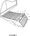
- the device 1 for use with a continuous track 3 of a vehicle is shown.
- the device may be used on any tracked vehicle to enhance traction in snowy or icy conditions, such as a digger, bulldozer, snowmobile, crawler, or tank, for example.
- the device 1 comprises a rigid elongate body 5 having a ground contacting surface 6 and a pair of brackets for releasably securing the elongate body 5 to the continuous track 3.
- the pair of brackets comprises a releasable bracket 7 and a fixed bracket 9.
- the brackets 7, 9 are rigid brackets.
- the releasable bracket 7 has a bracket body 11 and first clamping members, in the form of a flange 13.
- the flange 13 is integrally formed with the bracket body.
- the flange 13 extends generally perpendicularly from the bracket body 11.
- the releasable bracket 7 has a second clamping member in the form of a bracket leg 15.
- the bracket leg 15 extends downwardly at an angle from the bracket body 11 and at a non-parallel angle relative to the flange 13.
- the angle is any suitable angle. In the embodiment shown, the angle is about 30°.
- the flange 13 also protects the fastener(s) from the cold temperatures caused by snow and ice.
- the releasable bracket 7 has at least one fastener 17 extending through the bracket body 11 into the elongate body 5.
- the releasable bracket 7 has a pair of fasteners 17.
- the fasteners 17 extend through clearance slots 19 in the bracket body 11 and engage with corresponding threaded holes (not visible) formed in the elongate body 5.
- the fasteners 17 are positioned in the lower part of the bracket body so that the clamping force provided by the fasteners 17 is close to the track shoe.
- the fixed bracket 9 is similar to the releasable bracket 7, except that it is permanently fixed to the elongate body 5.
- the fixed bracket has a bracket body 25 and a bracket leg 27 extending downwardly at an angle from the bracket body 25.
- the elongate body 5 has a generally flat and planar top surface and the ground contacting surface 6 is a generally flat top surface. This is useful in snowy or icy conditions because the flat profile prevents snow or ice from building up on the ground contacting surface 6.
- the cross-sectional profile of the ground contacting surface 6 is generally constant along the length of the elongate body 5.
- the ground engaging features 29 have a plurality of teeth, sharp points or serrations 31.
- the ground engaging features 29 are operatively attached to the elongate body 5.
- the ground engaging features 29 are attached directly to the elongate body 5 by welding.
- the ground engaging features may be attached by single or double welding.
- the ground engaging features 29 may be connected to the elongate body 5 via spacers or other components.
- the device has a first ground engaging feature 29A and second ground engaging feature 29B operatively attached to the elongate body and projecting beyond the surface of the elongate body.
- first ground engaging feature 29A has a plurality of teeth 31 arranged in a line 33 and the second ground engaging feature 29B has a plurality of teeth 31 arranged in a line 35.
- the line 33 of the first ground engaging feature 29A extends at an angle B relative to the longitudinal axis of the elongate body and at an angle C relative to the line 35 of the second ground engaging feature 29B.
- the angle C between the lines of teeth is about 120 degrees.
- the angle B between the line of teeth of the first ground engaging feature and the longitudinal axis of the device is about 30 degrees.
- the angle A between the line of teeth of the second ground engaging feature and the longitudinal axis of the device is about 30 degrees.
- the line of teeth may extend at other angles, such as about 20 degrees, 40 degrees, 45 degrees, 50 degrees, or 60 degrees, for example. Angle A may be the same as angle B, or they may be different. In another alternative embodiment, the lines may not be straight lines.
- Each ground engaging feature 29 is a plate-like component with the teeth 31 having a constant profile from one side of the plate to the other side of the plate.
- the profile may vary from one side of the tooth to the other side of the tooth.
- the teeth 31 are connected together to form a saw tooth-like part.
- the teeth 31 may be separate parts.
- the teeth 31 may be integrally formed with the elongate body 5 or formed as separate components that are welded to the elongate body.
- Each of the teeth has a generally chevron or inverted V-shaped ground engaging surface. That shape allows the teeth to bite into ice or snow and provide grip to the tracked vehicle.
- the first ground engaging feature 29A is spaced at a distance from the second ground engaging feature 29B to provide a clearance space 37.
- the clearance space 37 allows the snow or ice to move free from between the ground engaging features. That is, the device 1 is self-cleaning of ice and snow that may otherwise become stuck on the device.
- the embodiment shown has third 29C and fourth 29D ground engaging features.
- the features and operation are similar to the first and second ground engaging features.
- the third and fourth ground engaging features are spaced from the first and second ground engaging features to provide additional clearance spaces 37.
- the elongate body 5 and the brackets 7, 9 may be formed from a suitable metallic material, such as mild steel or medium tensile steel.
- the elongate body 5 is formed from a single length of steel.
- the elongate body 5 also could be made out of two pieces of sheet or plate material, which are then bent into shape and welded along the top to form a shape generally as shown.
- the teeth may be formed from high tensile steel.
- a suitable high tensile steel may have a Rockwell C hardness of about 40 to about 50.
- the brackets 7, 9 may be formed from steel plate and bent into the required shape. Alternatively, the brackets 7,9 may be cast into the required shape.
- the flange 13 of the releasable bracket 7 may be formed by welding bolts or rods to the bracket body.
- the fixed bracket 9 may be welded to the elongate body 5.
- the fixed bracket 9 may be formed as a separate component that is fixed to the elongate body 5, for example, by fasteners.
- the elongate body 5 and fixed bracket may 9 be formed as a single integral component.
- the elongate body 5 is placed on the track.
- the elongate body 5 is adapted to nest between ribs of a rigid track shoe of the continuous track.
- the elongate body 5 nests between two side ribs of the track shoe and extends the transverse length of the shoe, between the side edges 3b of the track.
- the elongate body 5 has a clearance slot 35 allowing the elongate body 5 to extend over the central rib.
- the elongate body 5 has further clearance slots allowing the elongate body 5 to sit over track fasteners.
- the elongate body 5 When assembled with the track shoe 3, the elongate body 5 substantially fills the gap between the side ribs and contacts the side ribs. Alternatively, the elongate body 5 may nest between two adjacent side ribs. The elongate body extends across the transverse length of the track shoe, from one end of the track shoe to the other end of the track shoe.
- the elongate body is placed on the track with the leg 27 of the fixed bracket positioned below the underside of the track.
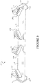
- the releasable bracket may be loosely attached to the elongate body 5 before assembly to the track to decrease the time required to attach the device to the track, as shown in Figure 3 .
- the releasable bracket may not be attached to the elongate body 5 before the device is placed on the track, as shown in Figure 2 .
- bracket body 11 and elongate body 5 are drawn together in a generally horizontal direction. Fastening the fastener causes the leg 15 to engage with the underside of the track shoe and draw the flange 13 towards the elongate body to releasably secure the elongate body to the continuous track.
- the bracket body 11 and elongate body 5 are drawn together, the end of the elongate body and the end of the track shoe are wedged between the flange 13 and the leg 15 to secure the elongate body 5 to the track 3.
- the flange contacts the top surface of the elongate body 5 and the leg contacts the underside surface of the track shoe.
- the secured bracket is shown in Figure 2 .
- the clearance slots 19 formed in the bracket body allow the bracket to move relative to the elongate body 5 in the generally vertical direction as the fastener is tightened.
- Tightening the releasable bracket to the track will simultaneously cause the fixed bracket and the other end of the elongate body 5 to be drawn towards the corresponding edge of the track. That movement releasably secures the other end of the elongate body 5 to the track. Due to the angle of the leg 27 that engages with the underside of the track shoe, that movement also pulls that end of the elongate body 5 down into secure engagement with the track shoe.
- the relative angle between the leg 15 and the flange 13 allows the device to be used on continuous tracks having different track shoe thicknesses because the distance between the flange 13 and the bracket leg 15 can be adjusted to suit thinner tracks by tightening the fasteners 17.
- a continuous track may have about five or six devices along the track, spaced about one metre apart.
- the number of devices used on a track can be chosen depending on the traction required for any particular situation.
- the device 1 may also be useful in situations where the vehicle is stuck, such as in very muddy situations.
- One end of a chain can be attached to the device 1 and the other end can be secured. The vehicle can then be driven forward by the vehicle pulling on the chain.
- the device 1 can be removed by loosening the fastener 17, which will release the releasable bracket 7 and the fixed bracket 9 from the track.
- the elongate body 5 can then be removed from the track.
- a second preferred embodiment of the device is shown.
- the features and operation of the second embodiment device are the same as the first embodiment described above, except as described below.
- Like numbers are used to indicate like parts with the addition of 100.
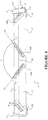
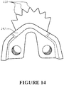
- the device has a first ground engaging feature 129A, second ground engaging feature 129B, and a third ground engaging feature 129C operatively attached to the elongate body 105.
- the ground engaging features 129A, 129B, 129C project beyond the surface of the elongate body 105.
- the first ground engaging feature 129A has a plurality of teeth 131 arranged in a line 141 and the second ground engaging feature 129B has a plurality of teeth 131 arranged in a line 145, when viewed from above.
- the line 145 of the first ground engaging feature 129A extends at an angle E relative to the longitudinal axis of the elongate body. Because the second ground engaging feature is parallel with the longitudinal axis, the line of the first ground engaging feature also extends at an angle relative to the line of the second ground engaging feature 129B.
- the line 141 of the third ground engaging feature 129C extends at an angle F relative to the longitudinal axis of the elongate body and at an angle (the same angle) relative to the line of the second ground engaging feature 129B.
- the angles are the same because the second ground engaging feature 129B extends in a direction parallel to the direction of the elongate axis of the device.
- the second ground engaging feature 129B suitably enhances traction of the vehicle in the running direction of the track and the first and third ground engaging features 129A, 129C enhance traction of the vehicle in a direction transverse to the running direction of the track, for example a direction that is perpendicular to the running direction of the track.
- the second ground engaging feature is supported at each end by a flange 130.
- the first and third ground engaging features 129A, 129C are shaped with the end points of the teeth 131 following a curved line.
- the angle E between the line of teeth of the first ground engaging feature 129A and the longitudinal axis of the device is about 90 degrees.
- the angle F between the line of teeth of the third ground engaging feature and the longitudinal axis of the device is about 90 degrees.
- the line of teeth may extend at other angles, such as about 80 degrees, 70 degrees, 60 degrees, 50 degrees, 40 degrees, 30 degrees, or 20 degrees for example.
- Angle A may be the same as angle B, or they may be different.
- the line may not be a straight line.
- the second ground engaging feature may extend at an angle relative to the elongate direction of the device, for example, five or ten degrees.
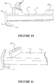
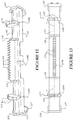
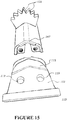
- Figure 15 shows the cross-section of the elongate body is generally V- shaped (inverted).
- the elongate body has a central section having two diverging portions and side walls that extend at a steeper angle than the central diverging portions. The central diverging portions are joined by a curved section.
- figures 15 and 16 show the elongate body has bent end 147.
- the bracket leg may extend generally perpendicularly from the bracket body and the flange may extend at a non-perpendicular angle relative to the bracket body.
- the bracket leg and flange may extend at non-perpendicular angles relative to the bracket body.
- the first clamping member is defined by a single flange.
- the first clamping member may be formed by any other suitable protrusion(s), such as ribs, plates, bosses or shoulders, for example. There may be one, two, or more protrusions that form the first clamping member.
- the ground-contacting surface may be formed with a textured surface and/or outwardly extending features to further enhance the traction of the device and the continuous track.
- the device may a multi-fit device that may be used for different tracked vehicles.
- a multi-fit device may be narrower, for example, to fit the various different types of tracks, or have features that allow the device to be positioned on or adjacent a grouser of a track shoe.
- the ground engaging features may not have serrations or teeth. That alternative embodiment is useful for quarry situations, for example, if a vehicle is stuck in the quarry.
Landscapes
- Engineering & Computer Science (AREA)
- Chemical & Material Sciences (AREA)
- Combustion & Propulsion (AREA)
- Transportation (AREA)
- Mechanical Engineering (AREA)
- Railway Tracks (AREA)
- Machines For Laying And Maintaining Railways (AREA)
- Road Paving Structures (AREA)
- Tires In General (AREA)
- Devices For Conveying Motion By Means Of Endless Flexible Members (AREA)
- Train Traffic Observation, Control, And Security (AREA)
Claims (13)
- Vorrichtung (1) zur Verwendung mit einer Gleiskette (3) eines Kettenfahrzeugs zur Verbesserung der Traktion des Fahrzeugs, wobei die Vorrichtung Folgendes umfasst:einen länglichen Körper (5, 105), der eine Oberfläche (6) und eine Längsachse aufweist;ein erstes bodeneingreifendes Merkmal (29A, 129A) und ein zweites bodeneingreifendes Merkmal (29B, 129B), die betriebsmäßig an dem länglichen Körper (5, 105) angebracht sind und über die Oberfläche des länglichen Körpers (5, 105) hinausragen, wobei das erste bodeneingreifende Merkmal (29A, 129A) eine Vielzahl von Zähnen aufweist, die in einer Linie angeordnet sind, das zweite bodeneingreifende Merkmal (29B, 129B) eine Vielzahl von Zähnen aufweist, die in einer Linie angeordnet sind, wobei sich die Linie des ersten bodeneingreifenden Merkmals (29A, 129A) in einem Winkel relativ zu der Längsachse des länglichen Körpers und in einem Winkel relativ zu der Linie des zweiten bodeneingreifenden Merkmals erstreckt (29B, 129B); undeinen lösbaren Bügel (7, 107) zum lösbaren Sichern des länglichen Körpers (5) an der Gleiskette (3), dadurch gekennzeichnet, dass der lösbare Bügel (7, 107) einen Bügelkörper (11, 111), ein erstes Klemmglied (13, 113), das sich von dem Bügelkörper (11, 111) erstreckt, ein zweites Klemmglied (15, 115), das sich von dem Bügelkörper in einem spitzen Winkel relativ zu dem ersten Klemmglied (13, 113) erstreckt, und ein Befestigungselement (17) umfasst, wobei der Bügel (7, 107) so angeordnet ist, dass das Befestigen des Befestigungsglieds (17) verursacht, dass der Bügelkörper (11, 111) den länglichen Körper (5, 105) und eine Kettenplatte der Gleiskette (3) zwischen dem ersten Klemmglied (13, 113) und dem zweiten Klemmglied einkeilt.
- Vorrichtung gemäß Anspruch 1, wobei das erste bodeneingreifende Merkmal (29A, 129A) in einem Abstand von dem zweiten bodeneingreifenden Merkmal (29B, 129B) beabstandet ist, um einen Freiraum (37) bereitzustellen.
- Vorrichtung gemäß Anspruch 1 oder Anspruch 2, wobei jeder der Zähne (31, 131) eine generell sparren- oder umgekehrte V-förmige bodeneingreifende Oberfläche aufweist.
- Vorrichtung gemäß einem der Ansprüche 1 bis 3, wobei der längliche Körper (5, 105) eine generell flache und planare bodeneingreifende Oberfläche (6) aufweist.
- Vorrichtung gemäß einem der Ansprüche 1 bis 4, wobei die Vorrichtung (1) an der Gleiskette (3) lösbar gesichert werden kann.
- Vorrichtung gemäß einem der Ansprüche 1 bis 5, wobei die Vorrichtung ferner einen weiteren Bügel (9, 109) zum lösbaren Sichern des länglichen Körpers (5, 105) an der äußeren Seitenkante der Gleiskette (3) umfasst, wobei der weitere Bügel (9, 109) einen Bügelkörper (25, 125) umfasst.
- Vorrichtung gemäß Anspruch 6, wobei der weitere Bügel (9, 109) ein fixierter Bügel ist, der an dem länglichen Körper (5, 105) permanent fixiert ist, oder wobei der weitere Bügel (9, 109) ein lösbarer Bügel ist, der an dem länglichen Körper (5, 105) lösbar gesichert ist.
- Vorrichtung gemäß einem der Ansprüche 1 bis 7, wobei der/die Bügel (7, 9, 107, 109) an dem/den Ende(n) des länglichen Körpers (5, 105) positioniert ist/sind.
- Kombination aus einer Kettenplatte und mindestens einer Vorrichtung (1) gemäß einem der vorhergehenden Ansprüche, die an der Kettenplatte gesichert ist.
- Kombination gemäß Anspruch 9, wobei die Kettenplatte Seitenrippen mit einem Spalt zwischen den Seitenrippen umfasst und der längliche Körper (5, 105) der Vorrichtung (1) im Wesentlichen den Spalt zwischen den Seitenrippen füllt und die Seitenrippen kontaktiert, wobei bevorzugt die Kettenplatte ferner eine Zwischenrippe umfasst, die zwischen den zwei Seitenrippen positioniert ist, und der längliche Körper (5, 105) zwischen zwei Seitenrippen der Kettenplatte eingebettet ist und sich über die Zwischenrippe erstreckt.
- Kombination gemäß einem der Ansprüche 9 bis 10, wobei sich der längliche Körper (5, 105) über die Querlänge der Kettenplatte, von einem Ende der Kettenplatte zu dem anderen Ende der Kettenplatte, erstreckt.
- Kombination gemäß einem der Ansprüche 9 bis 11, wobei die Vorrichtung (1) an der Gleiskette (3) lösbar gesichert ist.
- Kombination aus einer Gleiskette mit mindestens einer Vorrichtung (1) gemäß einem der Ansprüche 1 bis 8, die an der Kette (3) gesichert ist.
Applications Claiming Priority (2)
| Application Number | Priority Date | Filing Date | Title |
|---|---|---|---|
| NZ71561215 | 2015-12-24 | ||
| PCT/NZ2016/050210 WO2017111624A1 (en) | 2015-12-24 | 2016-12-23 | A device to enhance the traction of a tracked vehicle |
Publications (3)
| Publication Number | Publication Date |
|---|---|
| EP3393894A1 EP3393894A1 (de) | 2018-10-31 |
| EP3393894A4 EP3393894A4 (de) | 2019-08-07 |
| EP3393894B1 true EP3393894B1 (de) | 2021-07-07 |
Family
ID=59090867
Family Applications (1)
| Application Number | Title | Priority Date | Filing Date |
|---|---|---|---|
| EP16879456.8A Active EP3393894B1 (de) | 2015-12-24 | 2016-12-23 | Vorrichtung zur verbesserung der traktion eines kettenfahrzeuges |
Country Status (5)
| Country | Link |
|---|---|
| US (1) | US11390341B2 (de) |
| EP (1) | EP3393894B1 (de) |
| CA (1) | CA3009647C (de) |
| RU (1) | RU2721434C2 (de) |
| WO (1) | WO2017111624A1 (de) |
Families Citing this family (7)
| Publication number | Priority date | Publication date | Assignee | Title |
|---|---|---|---|---|
| DE102018106962A1 (de) * | 2018-03-23 | 2019-09-26 | Engelhardt Verwaltungs- und Dienstleistungs GmbH & Co. KG | Laufwerkskette für eine Pistenraupe und Verfahren zur Präparierung einer Skipiste mit einer Pistenraupe |
| US12246784B2 (en) * | 2018-11-16 | 2025-03-11 | Jb Innovations Limited | Device to enhance the traction of a tracked vehicle |
| US11427041B2 (en) * | 2020-01-15 | 2022-08-30 | Stanley Young | Chain system for a continuous track |
| US20220266932A1 (en) * | 2021-02-22 | 2022-08-25 | Edgar Michael | Systems, Devices, and/or Methods for Managing Vehicle Tracks |
| EP4088994B1 (de) * | 2021-05-10 | 2023-12-13 | pewag Schneeketten GmbH & Co KG | Gleitschutzvorrichtung |
| AU2023381553A1 (en) * | 2022-11-16 | 2025-06-19 | Jb Innovations Limited | Device for enhancing traction of a tracked vehicle |
| US11932331B2 (en) * | 2023-01-06 | 2024-03-19 | Chains for Tracks, Inc. | External traction device for endless tracks |
Family Cites Families (24)
| Publication number | Priority date | Publication date | Assignee | Title |
|---|---|---|---|---|
| US1832926A (en) | 1929-12-16 | 1931-11-24 | Edstedt John | Renewable grouser |
| US3717387A (en) | 1970-11-12 | 1973-02-20 | Caterpillar Tractor Co | Cushioned track with cross grousers |
| US4043610A (en) * | 1976-08-23 | 1977-08-23 | General Motors Corporation | Track shoe |
| SU839825A1 (ru) * | 1979-09-27 | 1981-06-23 | Предприятие П/Я А-1495 | Гусенична лента транспортногоСРЕдСТВА |
| WO1991004186A1 (en) * | 1989-09-20 | 1991-04-04 | Joseph Berto | Cleat for snowmobiles and the like |
| US5388900A (en) | 1992-07-15 | 1995-02-14 | Kabushiki Kaisha Suzuki Shoji | Crawler pad |
| CA2137859A1 (en) * | 1994-12-12 | 1996-06-13 | Gilles Soucy | Track for a vehicle |
| US5713645A (en) | 1995-02-22 | 1998-02-03 | Bombardier Inc. | Snowmobile track profile |
| AU671250B3 (en) * | 1995-09-13 | 1996-08-15 | Art Japan Co. Ltd. | Caterpillar track shoe cover for protection of road surface |
| JP3017182B1 (ja) | 1998-09-29 | 2000-03-06 | 富太郎 服部 | 履帯用パッド |
| US6299265B1 (en) | 1999-12-27 | 2001-10-09 | Ronald J. Hoffart | Replaceable tire gripping system for endless track |
| JP2001253375A (ja) | 2000-03-10 | 2001-09-18 | Topy Ind Ltd | 無限軌道帯用パッド付き履板 |
| US6540310B1 (en) | 2002-02-01 | 2003-04-01 | Ironwood Designs Llc | Grouser |
| US20030184157A1 (en) * | 2002-03-26 | 2003-10-02 | Mcnutt Thomas | Grouser assembly |
| JP2004058688A (ja) | 2002-07-24 | 2004-02-26 | Komatsu Ltd | 履帯用履板 |
| US20040174068A1 (en) | 2002-12-05 | 2004-09-09 | Mcnutt Thomas Walton | Grouser assembly |
| GEP20053576B (en) * | 2004-07-09 | 2005-07-11 | Caterpillar Track | |
| US7901015B1 (en) * | 2007-03-23 | 2011-03-08 | Deloren E. Anderson | Traction cleats for tracked construction equipment |
| CA2698731C (en) * | 2007-09-07 | 2017-02-21 | Loegering Mfg. Inc. | Apparatus for converting a wheeled vehicle to a tracked vehicle |
| AU2011213365B2 (en) | 2010-02-08 | 2016-04-28 | John Menzies Burling | A device to enhance the traction of a tracked vehicle |
| DE202013011423U1 (de) | 2013-12-20 | 2014-02-18 | Hans Hall Gmbh | Raupensteg für ein Pistenfahrzeug sowie Raupenkette mit Raupenstege |
| US9950757B2 (en) * | 2015-12-08 | 2018-04-24 | Tibbits Equipment Services, Inc. | Traction cleat for a tracked vehicle |
| US10967925B2 (en) * | 2017-05-04 | 2021-04-06 | Pro-Lynx Inc. | Mountable cleat apparatus |
| AT520750B1 (de) * | 2018-03-21 | 2019-07-15 | Rupert Hettegger | Steighilfe |
-
2016
- 2016-12-23 US US16/065,605 patent/US11390341B2/en active Active
- 2016-12-23 EP EP16879456.8A patent/EP3393894B1/de active Active
- 2016-12-23 RU RU2018126946A patent/RU2721434C2/ru active
- 2016-12-23 WO PCT/NZ2016/050210 patent/WO2017111624A1/en not_active Ceased
- 2016-12-23 CA CA3009647A patent/CA3009647C/en active Active
Also Published As
| Publication number | Publication date |
|---|---|
| EP3393894A1 (de) | 2018-10-31 |
| RU2018126946A (ru) | 2020-01-27 |
| NZ744143A (en) | 2023-09-29 |
| RU2018126946A3 (de) | 2020-03-26 |
| CA3009647C (en) | 2023-12-05 |
| CA3009647A1 (en) | 2017-06-29 |
| WO2017111624A1 (en) | 2017-06-29 |
| RU2721434C2 (ru) | 2020-05-19 |
| US11390341B2 (en) | 2022-07-19 |
| EP3393894A4 (de) | 2019-08-07 |
| US20210163087A1 (en) | 2021-06-03 |
Similar Documents
| Publication | Publication Date | Title |
|---|---|---|
| EP3393894B1 (de) | Vorrichtung zur verbesserung der traktion eines kettenfahrzeuges | |
| US12246784B2 (en) | Device to enhance the traction of a tracked vehicle | |
| CA2789136C (en) | A device to enhance the traction of a tracked vehicle | |
| US9950757B2 (en) | Traction cleat for a tracked vehicle | |
| CA2881247C (en) | Detachable traction system for endless track vehicles | |
| CA2712009C (en) | Cross-links for a track of a tracked vehicle | |
| US20030184157A1 (en) | Grouser assembly | |
| CA2567645C (en) | Traction chain assembly for elastomeric tracks | |
| NZ744143B2 (en) | A device to enhance the traction of a tracked vehicle | |
| JP3829082B2 (ja) | 無限軌道用滑り止め金具、およびその装着方法 | |
| JP3143792U (ja) | ゴムクローラの滑り止め装置 | |
| US20100193263A1 (en) | Traction apparatus to improve winter operation of rubber tracks on endless track vehicles | |
| NZ717936A (en) | A device to enhance the traction of a tracked vehicle | |
| JP5854431B2 (ja) | 装軌式車両の路面損傷防止具 | |
| JP3155173U (ja) | 鉄クローラの滑り止め装置 | |
| KR20090054082A (ko) | 차량용 미끄럼 방지장치 | |
| CN107922024B (zh) | 用于特别为积雪清理机的履带式车辆的履带的交叉链节 | |
| CA1084563A (en) | Snowmobile traction stud and mounting | |
| KR20130014995A (ko) | 차량용 스노우 체인 패드 | |
| JPH10157662A (ja) | クローラ構成部品 |
Legal Events
| Date | Code | Title | Description |
|---|---|---|---|
| STAA | Information on the status of an ep patent application or granted ep patent |
Free format text: STATUS: THE INTERNATIONAL PUBLICATION HAS BEEN MADE |
|
| PUAI | Public reference made under article 153(3) epc to a published international application that has entered the european phase |
Free format text: ORIGINAL CODE: 0009012 |
|
| STAA | Information on the status of an ep patent application or granted ep patent |
Free format text: STATUS: REQUEST FOR EXAMINATION WAS MADE |
|
| 17P | Request for examination filed |
Effective date: 20180723 |
|
| AK | Designated contracting states |
Kind code of ref document: A1 Designated state(s): AL AT BE BG CH CY CZ DE DK EE ES FI FR GB GR HR HU IE IS IT LI LT LU LV MC MK MT NL NO PL PT RO RS SE SI SK SM TR |
|
| AX | Request for extension of the european patent |
Extension state: BA ME |
|
| DAV | Request for validation of the european patent (deleted) | ||
| DAX | Request for extension of the european patent (deleted) | ||
| A4 | Supplementary search report drawn up and despatched |
Effective date: 20190709 |
|
| RIC1 | Information provided on ipc code assigned before grant |
Ipc: B62D 55/28 20060101AFI20190703BHEP |
|
| GRAP | Despatch of communication of intention to grant a patent |
Free format text: ORIGINAL CODE: EPIDOSNIGR1 |
|
| STAA | Information on the status of an ep patent application or granted ep patent |
Free format text: STATUS: GRANT OF PATENT IS INTENDED |
|
| INTG | Intention to grant announced |
Effective date: 20210203 |
|
| GRAS | Grant fee paid |
Free format text: ORIGINAL CODE: EPIDOSNIGR3 |
|
| GRAA | (expected) grant |
Free format text: ORIGINAL CODE: 0009210 |
|
| STAA | Information on the status of an ep patent application or granted ep patent |
Free format text: STATUS: THE PATENT HAS BEEN GRANTED |
|
| AK | Designated contracting states |
Kind code of ref document: B1 Designated state(s): AL AT BE BG CH CY CZ DE DK EE ES FI FR GB GR HR HU IE IS IT LI LT LU LV MC MK MT NL NO PL PT RO RS SE SI SK SM TR |
|
| REG | Reference to a national code |
Ref country code: GB Ref legal event code: FG4D |
|
| REG | Reference to a national code |
Ref country code: AT Ref legal event code: REF Ref document number: 1408336 Country of ref document: AT Kind code of ref document: T Effective date: 20210715 |
|
| REG | Reference to a national code |
Ref country code: DE Ref legal event code: R096 Ref document number: 602016060456 Country of ref document: DE |
|
| REG | Reference to a national code |
Ref country code: IE Ref legal event code: FG4D |
|
| REG | Reference to a national code |
Ref country code: LT Ref legal event code: MG9D |
|
| REG | Reference to a national code |
Ref country code: NL Ref legal event code: MP Effective date: 20210707 |
|
| REG | Reference to a national code |
Ref country code: NO Ref legal event code: T2 Effective date: 20210707 |
|
| PG25 | Lapsed in a contracting state [announced via postgrant information from national office to epo] |
Ref country code: BG Free format text: LAPSE BECAUSE OF FAILURE TO SUBMIT A TRANSLATION OF THE DESCRIPTION OR TO PAY THE FEE WITHIN THE PRESCRIBED TIME-LIMIT Effective date: 20211007 Ref country code: LT Free format text: LAPSE BECAUSE OF FAILURE TO SUBMIT A TRANSLATION OF THE DESCRIPTION OR TO PAY THE FEE WITHIN THE PRESCRIBED TIME-LIMIT Effective date: 20210707 Ref country code: HR Free format text: LAPSE BECAUSE OF FAILURE TO SUBMIT A TRANSLATION OF THE DESCRIPTION OR TO PAY THE FEE WITHIN THE PRESCRIBED TIME-LIMIT Effective date: 20210707 Ref country code: FI Free format text: LAPSE BECAUSE OF FAILURE TO SUBMIT A TRANSLATION OF THE DESCRIPTION OR TO PAY THE FEE WITHIN THE PRESCRIBED TIME-LIMIT Effective date: 20210707 Ref country code: ES Free format text: LAPSE BECAUSE OF FAILURE TO SUBMIT A TRANSLATION OF THE DESCRIPTION OR TO PAY THE FEE WITHIN THE PRESCRIBED TIME-LIMIT Effective date: 20210707 Ref country code: PT Free format text: LAPSE BECAUSE OF FAILURE TO SUBMIT A TRANSLATION OF THE DESCRIPTION OR TO PAY THE FEE WITHIN THE PRESCRIBED TIME-LIMIT Effective date: 20211108 Ref country code: NL Free format text: LAPSE BECAUSE OF FAILURE TO SUBMIT A TRANSLATION OF THE DESCRIPTION OR TO PAY THE FEE WITHIN THE PRESCRIBED TIME-LIMIT Effective date: 20210707 Ref country code: RS Free format text: LAPSE BECAUSE OF FAILURE TO SUBMIT A TRANSLATION OF THE DESCRIPTION OR TO PAY THE FEE WITHIN THE PRESCRIBED TIME-LIMIT Effective date: 20210707 Ref country code: SE Free format text: LAPSE BECAUSE OF FAILURE TO SUBMIT A TRANSLATION OF THE DESCRIPTION OR TO PAY THE FEE WITHIN THE PRESCRIBED TIME-LIMIT Effective date: 20210707 |
|
| PG25 | Lapsed in a contracting state [announced via postgrant information from national office to epo] |
Ref country code: PL Free format text: LAPSE BECAUSE OF FAILURE TO SUBMIT A TRANSLATION OF THE DESCRIPTION OR TO PAY THE FEE WITHIN THE PRESCRIBED TIME-LIMIT Effective date: 20210707 Ref country code: LV Free format text: LAPSE BECAUSE OF FAILURE TO SUBMIT A TRANSLATION OF THE DESCRIPTION OR TO PAY THE FEE WITHIN THE PRESCRIBED TIME-LIMIT Effective date: 20210707 Ref country code: GR Free format text: LAPSE BECAUSE OF FAILURE TO SUBMIT A TRANSLATION OF THE DESCRIPTION OR TO PAY THE FEE WITHIN THE PRESCRIBED TIME-LIMIT Effective date: 20211008 |
|
| REG | Reference to a national code |
Ref country code: DE Ref legal event code: R097 Ref document number: 602016060456 Country of ref document: DE |
|
| PG25 | Lapsed in a contracting state [announced via postgrant information from national office to epo] |
Ref country code: DK Free format text: LAPSE BECAUSE OF FAILURE TO SUBMIT A TRANSLATION OF THE DESCRIPTION OR TO PAY THE FEE WITHIN THE PRESCRIBED TIME-LIMIT Effective date: 20210707 |
|
| PLBE | No opposition filed within time limit |
Free format text: ORIGINAL CODE: 0009261 |
|
| STAA | Information on the status of an ep patent application or granted ep patent |
Free format text: STATUS: NO OPPOSITION FILED WITHIN TIME LIMIT |
|
| PG25 | Lapsed in a contracting state [announced via postgrant information from national office to epo] |
Ref country code: SM Free format text: LAPSE BECAUSE OF FAILURE TO SUBMIT A TRANSLATION OF THE DESCRIPTION OR TO PAY THE FEE WITHIN THE PRESCRIBED TIME-LIMIT Effective date: 20210707 Ref country code: SK Free format text: LAPSE BECAUSE OF FAILURE TO SUBMIT A TRANSLATION OF THE DESCRIPTION OR TO PAY THE FEE WITHIN THE PRESCRIBED TIME-LIMIT Effective date: 20210707 Ref country code: RO Free format text: LAPSE BECAUSE OF FAILURE TO SUBMIT A TRANSLATION OF THE DESCRIPTION OR TO PAY THE FEE WITHIN THE PRESCRIBED TIME-LIMIT Effective date: 20210707 Ref country code: EE Free format text: LAPSE BECAUSE OF FAILURE TO SUBMIT A TRANSLATION OF THE DESCRIPTION OR TO PAY THE FEE WITHIN THE PRESCRIBED TIME-LIMIT Effective date: 20210707 Ref country code: CZ Free format text: LAPSE BECAUSE OF FAILURE TO SUBMIT A TRANSLATION OF THE DESCRIPTION OR TO PAY THE FEE WITHIN THE PRESCRIBED TIME-LIMIT Effective date: 20210707 Ref country code: AL Free format text: LAPSE BECAUSE OF FAILURE TO SUBMIT A TRANSLATION OF THE DESCRIPTION OR TO PAY THE FEE WITHIN THE PRESCRIBED TIME-LIMIT Effective date: 20210707 |
|
| 26N | No opposition filed |
Effective date: 20220408 |
|
| PG25 | Lapsed in a contracting state [announced via postgrant information from national office to epo] |
Ref country code: MC Free format text: LAPSE BECAUSE OF FAILURE TO SUBMIT A TRANSLATION OF THE DESCRIPTION OR TO PAY THE FEE WITHIN THE PRESCRIBED TIME-LIMIT Effective date: 20210707 Ref country code: IT Free format text: LAPSE BECAUSE OF FAILURE TO SUBMIT A TRANSLATION OF THE DESCRIPTION OR TO PAY THE FEE WITHIN THE PRESCRIBED TIME-LIMIT Effective date: 20210707 |
|
| REG | Reference to a national code |
Ref country code: CH Ref legal event code: PL |
|
| REG | Reference to a national code |
Ref country code: BE Ref legal event code: MM Effective date: 20211231 |
|
| PG25 | Lapsed in a contracting state [announced via postgrant information from national office to epo] |
Ref country code: LU Free format text: LAPSE BECAUSE OF NON-PAYMENT OF DUE FEES Effective date: 20211223 Ref country code: IE Free format text: LAPSE BECAUSE OF NON-PAYMENT OF DUE FEES Effective date: 20211223 |
|
| PG25 | Lapsed in a contracting state [announced via postgrant information from national office to epo] |
Ref country code: BE Free format text: LAPSE BECAUSE OF NON-PAYMENT OF DUE FEES Effective date: 20211231 |
|
| PG25 | Lapsed in a contracting state [announced via postgrant information from national office to epo] |
Ref country code: LI Free format text: LAPSE BECAUSE OF NON-PAYMENT OF DUE FEES Effective date: 20211231 Ref country code: CH Free format text: LAPSE BECAUSE OF NON-PAYMENT OF DUE FEES Effective date: 20211231 |
|
| PG25 | Lapsed in a contracting state [announced via postgrant information from national office to epo] |
Ref country code: CY Free format text: LAPSE BECAUSE OF FAILURE TO SUBMIT A TRANSLATION OF THE DESCRIPTION OR TO PAY THE FEE WITHIN THE PRESCRIBED TIME-LIMIT Effective date: 20210707 |
|
| PG25 | Lapsed in a contracting state [announced via postgrant information from national office to epo] |
Ref country code: HU Free format text: LAPSE BECAUSE OF FAILURE TO SUBMIT A TRANSLATION OF THE DESCRIPTION OR TO PAY THE FEE WITHIN THE PRESCRIBED TIME-LIMIT; INVALID AB INITIO Effective date: 20161223 |
|
| REG | Reference to a national code |
Ref country code: AT Ref legal event code: UEP Ref document number: 1408336 Country of ref document: AT Kind code of ref document: T Effective date: 20210707 |
|
| PG25 | Lapsed in a contracting state [announced via postgrant information from national office to epo] |
Ref country code: MK Free format text: LAPSE BECAUSE OF FAILURE TO SUBMIT A TRANSLATION OF THE DESCRIPTION OR TO PAY THE FEE WITHIN THE PRESCRIBED TIME-LIMIT Effective date: 20210707 |
|
| PG25 | Lapsed in a contracting state [announced via postgrant information from national office to epo] |
Ref country code: TR Free format text: LAPSE BECAUSE OF FAILURE TO SUBMIT A TRANSLATION OF THE DESCRIPTION OR TO PAY THE FEE WITHIN THE PRESCRIBED TIME-LIMIT Effective date: 20210707 |
|
| PG25 | Lapsed in a contracting state [announced via postgrant information from national office to epo] |
Ref country code: MT Free format text: LAPSE BECAUSE OF FAILURE TO SUBMIT A TRANSLATION OF THE DESCRIPTION OR TO PAY THE FEE WITHIN THE PRESCRIBED TIME-LIMIT Effective date: 20210707 |
|
| PGFP | Annual fee paid to national office [announced via postgrant information from national office to epo] |
Ref country code: GB Payment date: 20241222 Year of fee payment: 9 |
|
| PGFP | Annual fee paid to national office [announced via postgrant information from national office to epo] |
Ref country code: FR Payment date: 20241226 Year of fee payment: 9 |
|
| PGFP | Annual fee paid to national office [announced via postgrant information from national office to epo] |
Ref country code: AT Payment date: 20241227 Year of fee payment: 9 |
|
| PGFP | Annual fee paid to national office [announced via postgrant information from national office to epo] |
Ref country code: DE Payment date: 20241227 Year of fee payment: 9 |
|
| PGFP | Annual fee paid to national office [announced via postgrant information from national office to epo] |
Ref country code: NO Payment date: 20241230 Year of fee payment: 9 |