EP3393839B1 - Fahrzeug mit über ein kardangelenk operativ verbundenem anhänger - Google Patents
Fahrzeug mit über ein kardangelenk operativ verbundenem anhänger Download PDFInfo
- Publication number
- EP3393839B1 EP3393839B1 EP16836237.4A EP16836237A EP3393839B1 EP 3393839 B1 EP3393839 B1 EP 3393839B1 EP 16836237 A EP16836237 A EP 16836237A EP 3393839 B1 EP3393839 B1 EP 3393839B1
- Authority
- EP
- European Patent Office
- Prior art keywords
- vehicle
- trailer
- angle
- cardan
- power take
- Prior art date
- Legal status (The legal status is an assumption and is not a legal conclusion. Google has not performed a legal analysis and makes no representation as to the accuracy of the status listed.)
- Active
Links
Images


Classifications
-
- A—HUMAN NECESSITIES
- A01—AGRICULTURE; FORESTRY; ANIMAL HUSBANDRY; HUNTING; TRAPPING; FISHING
- A01B—SOIL WORKING IN AGRICULTURE OR FORESTRY; PARTS, DETAILS, OR ACCESSORIES OF AGRICULTURAL MACHINES OR IMPLEMENTS, IN GENERAL
- A01B71/00—Construction or arrangement of setting or adjusting mechanisms, of implement or tool drive or of power take-off; Means for protecting parts against dust, or the like; Adapting machine elements to or for agricultural purposes
- A01B71/02—Setting or adjusting mechanisms
-
- A—HUMAN NECESSITIES
- A01—AGRICULTURE; FORESTRY; ANIMAL HUSBANDRY; HUNTING; TRAPPING; FISHING
- A01B—SOIL WORKING IN AGRICULTURE OR FORESTRY; PARTS, DETAILS, OR ACCESSORIES OF AGRICULTURAL MACHINES OR IMPLEMENTS, IN GENERAL
- A01B59/00—Devices specially adapted for connection between animals or tractors and agricultural machines or implements
- A01B59/04—Devices specially adapted for connection between animals or tractors and agricultural machines or implements for machines pulled or pushed by a tractor
- A01B59/042—Devices specially adapted for connection between animals or tractors and agricultural machines or implements for machines pulled or pushed by a tractor having pulling means arranged on the rear part of the tractor
-
- A—HUMAN NECESSITIES
- A01—AGRICULTURE; FORESTRY; ANIMAL HUSBANDRY; HUNTING; TRAPPING; FISHING
- A01B—SOIL WORKING IN AGRICULTURE OR FORESTRY; PARTS, DETAILS, OR ACCESSORIES OF AGRICULTURAL MACHINES OR IMPLEMENTS, IN GENERAL
- A01B76/00—Parts, details or accessories of agricultural machines or implements, not provided for in groups A01B51/00 - A01B75/00
-
- B—PERFORMING OPERATIONS; TRANSPORTING
- B60—VEHICLES IN GENERAL
- B60K—ARRANGEMENT OR MOUNTING OF PROPULSION UNITS OR OF TRANSMISSIONS IN VEHICLES; ARRANGEMENT OR MOUNTING OF PLURAL DIVERSE PRIME-MOVERS IN VEHICLES; AUXILIARY DRIVES FOR VEHICLES; INSTRUMENTATION OR DASHBOARDS FOR VEHICLES; ARRANGEMENTS IN CONNECTION WITH COOLING, AIR INTAKE, GAS EXHAUST OR FUEL SUPPLY OF PROPULSION UNITS IN VEHICLES
- B60K25/00—Auxiliary drives
- B60K25/06—Auxiliary drives from the transmission power take-off
-
- A—HUMAN NECESSITIES
- A01—AGRICULTURE; FORESTRY; ANIMAL HUSBANDRY; HUNTING; TRAPPING; FISHING
- A01C—PLANTING; SOWING; FERTILISING
- A01C23/00—Distributing devices specially adapted for liquid manure or other fertilising liquid, including ammonia, e.g. transport tanks or sprinkling wagons
- A01C23/04—Distributing under pressure; Distributing mud; Adaptation of watering systems for fertilising-liquids
- A01C23/047—Spraying of liquid fertilisers
-
- A—HUMAN NECESSITIES
- A01—AGRICULTURE; FORESTRY; ANIMAL HUSBANDRY; HUNTING; TRAPPING; FISHING
- A01D—HARVESTING; MOWING
- A01D2101/00—Lawn-mowers
-
- A—HUMAN NECESSITIES
- A01—AGRICULTURE; FORESTRY; ANIMAL HUSBANDRY; HUNTING; TRAPPING; FISHING
- A01D—HARVESTING; MOWING
- A01D34/00—Mowers; Mowing apparatus of harvesters
- A01D34/01—Mowers; Mowing apparatus of harvesters characterised by features relating to the type of cutting apparatus
- A01D34/412—Mowers; Mowing apparatus of harvesters characterised by features relating to the type of cutting apparatus having rotating cutters
- A01D34/416—Flexible line cutters
-
- A—HUMAN NECESSITIES
- A01—AGRICULTURE; FORESTRY; ANIMAL HUSBANDRY; HUNTING; TRAPPING; FISHING
- A01D—HARVESTING; MOWING
- A01D34/00—Mowers; Mowing apparatus of harvesters
- A01D34/01—Mowers; Mowing apparatus of harvesters characterised by features relating to the type of cutting apparatus
- A01D34/412—Mowers; Mowing apparatus of harvesters characterised by features relating to the type of cutting apparatus having rotating cutters
- A01D34/63—Mowers; Mowing apparatus of harvesters characterised by features relating to the type of cutting apparatus having rotating cutters having cutters rotating about a vertical axis
- A01D34/64—Mowers; Mowing apparatus of harvesters characterised by features relating to the type of cutting apparatus having rotating cutters having cutters rotating about a vertical axis mounted on a vehicle, e.g. a tractor, or drawn by an animal or a vehicle
-
- B—PERFORMING OPERATIONS; TRANSPORTING
- B60—VEHICLES IN GENERAL
- B60Y—INDEXING SCHEME RELATING TO ASPECTS CROSS-CUTTING VEHICLE TECHNOLOGY
- B60Y2200/00—Type of vehicle
- B60Y2200/20—Off-Road Vehicles
- B60Y2200/22—Agricultural vehicles
- B60Y2200/221—Tractors
Definitions
- the present invention relates to a vehicle with a trailer, operatively connected thereto by means of a cardan.
- the present invention relates to a vehicle for agricultural use.
- the tractor is very often used to tow trailers for the most diverse uses.
- tractors are often used to tow other agricultural machines, for example to fertilise the soil, to spray leaves or to cut excessively long branches or grass.
- tractor-towed machines normally require energy in order to operate.
- the power take-off consists of a mechanical connection between tractor and trailer, which allows, by turning under the action of the engine of the tractor, to apply to towed machines the mechanical energy developed by the engine of the tractor, so as to exploit more fully the energy which moves the tractor.
- the power take-off is constituted by a rod, set in rotation by the engine of the tractor, consisting in a substantial protrusion of the transmission shaft of the tractor and which carries the same rotation to a motor shaft of the towed machine.
- Said projection is a slotted male element, designed to fit into the slotted female element of a cardan. For example, in this way, it is possible to operate a pump for spraying liquids or to fertilise.
- the rod of the power take-off is realised with a cardan that allows the transmission of the tractor curve to the trailer, allowing under certain circumstances to maintain rod rotation and power transmission.
- the most common power take-offs allow even high rotation speeds, for example between 500 and 1000 revolutions per minute.
- Most power take-offs rotate at 540 rpm or 1,000 rpm or offer the possibility to select one of these two speeds.
- Some more advanced models provide for the proportionality of the rotation of the cardan to the speed of the tractor engine.
- the cardan can work correctly at angles formed between the rear of the tractor and/or between the front of the trailer (perpendicular to the axles of the tractor and the trailer) and said cardan up to about 35°; a curve that results in the creation of smaller (or greater than 145°) angles between the vehicle and the cardan causes breakage of the cardan, with the stop of the operation in progress and a long and costly replacement. For this reason, those driving the tractor, arrived at the end of the row, must manually disengage the power take-off, thus suspending the rotation of the cardan, perform the conversion and, when the curve is over and the angle returns toward 90°, engage again the power take-off, thereby restoring the rotation of the cardan.
- US 2003/0 024 782 discloses a tool-bearing tractor which presents a hydraulic engagement and which protects the cardan from breakage due to excessively narrow angles in the lifting-lowering of the loading platform.
- tool-bearing means that the hydraulic lifting device of the tractor bears a tool. This is achieved by using a solenoid valve which, at the exceeding of a threshold value, disengages the hydraulic engagement.
- this document does not refer to a towed load and an accidentally exceeded threshold angle that the cardan forms on a vertical plane (the only angle that the cardan may form in a tool-bearing vehicle is that linked to raising and lowering of the hydraulic lifting device) is, however, a rare occurrence, usually linked to poor driving of the vehicle.
- the two types of vehicle with a towed or borne trailer are clearly distinct, so that a transposition of any technical arrangement from a load bearing vehicle to a load-towing vehicle is not feasible, precisely because they are completely different in their own nature and conception.
- the problem underlying the invention is to propose a vehicle structure with towed trailer which avoids breakage of the cardan due to creation of excessively narrow angles on the horizontal plane and which allows a continuous driving by the operator, thus obtaining the engagement and disengagement of a power take-off, without any intervention by the operator.
- a vehicle with trailer operatively connected thereto through a cardan, comprising sensing means of the angle between the vehicle and the cardan, between the trailer and the cardan or between the vehicle and the trailer, comparison means of the angle with a threshold angle and means which disengage the power take-off upon exceeding in one direction the threshold angle and which engage it when the angle exceeds again the threshold angle in the opposite direction, characterised in that said trailer is a towed load and in that sensing means of the angle are arranged around the cardan.
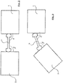
- the tractor 1 is a normal agricultural tractor, of the type that is commonly found on the market, except for what will be described below.
- the trailer 2 is a normal towed trailer for agricultural machines; it can carry a sprayer, a string trimmer, a lawn-mower, a collecting machine or other.
- the cardan 3 is, in itself, an ordinary cardan, to be used for power take-off.
- sensing means 4 of the angle ⁇ which the cardan 3 forms with the tractor 1 and the angle ⁇ that the same cardan 3 forms with the trailer 2 are arranged between the tractor 1 and the cardan 3 and between the trailer 2 and the cardan 3, in contact with the same cardan 3, so that these angles are known in any moment of vehicle travel.
- the means 4 may be any means adapted for sensing an angle.
- they may be electrovalves, pneumatic valves, infrared sensors, optic fibre sensors or photocells. Such devices are mostly simple, whilst giving sufficiently accurate results.
- Said means 4 are preferably arranged on the tractor 1 and trailer 2, for simplicity of construction. It is also possible to have the means 4 on the ends of the cardan 3, facing respectively towards the tractor 1 and trailer 2. Since, however, for safety reasons, the cardan 3 is generally covered by a casing (not shown in the drawings), the means 4 in this case must necessarily exit the casing itself.
- the means 4 for sensing angles ⁇ ; ⁇ are arranged around the cardan (3), so that they can easily and immediately sense any angular movement.
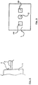
- Fig. 5 shows an embodiment of the present invention, in which said sensing means, 4A and 4B, are provided in two specimens, arranged preferably at 180° with respect to each other, so as to detect the right-left angular movements with a very simplified construction.
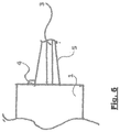
- a single sensing means 4 preferably an electrovalve, so that the movement automatically entails the sensing of the angle - is positioned on the tractor 1 and/or on the trailer 2, contacting a sleeve 5 that is made to fit on the cardan 3 or, rather, on the casing normally present on the cardan 3, to be able to detect any movement in any direction.
- FIG. 7 to 9 Another alternative embodiment is illustrated in Figs. 7 to 9 .
- the sensors 4, for example considering of constituted by an electrovalve, carry contact plates 6, to be placed on the cardan 3.
- Figures 7 to 10 also show a lever 7 to engage and disengage the power take-off, connected via an arm 8 to a motor 9.
- Said motor 9 is preferably an electric motor, but any other type of motor can be used, without thereby affecting the operation of the present embodiment.
- the tractor 1 When the tractor 1 is used to tow the trailer 2, it starts from a situation such as that illustrated in Fig. 2 . In this situation, the angle ⁇ and the angle ⁇ are both equal to 90°. In this situation, it is possible to insert the power take-off and the cardan 3 starts to rotate at the desired speed. In this way, the rotation of the engine of the tractor 1 transmits energy to the cardan 3 that rotates and, in turn, brings the motor, which drives the equipment contained inside the trailer 2 in rotation. For example, if verdigris is sprayed on the vines, this movement goes along each row and the movement of cardan 3 puts in rotation the motor of a pump contained in the trailer 2, which draws the verdigris solution from a dedicated tank and sprays it on vine leaves.
- the sensors 4 continuously sense the angles ⁇ and ⁇ , sending their value to an appropriate data processing unit, not illustrated in the drawings.
- FIG. 5 An arrangement as that of Fig. 5 is used to sense the angles ⁇ and ⁇ in the right and left directions with respect to the travel direction of the vehicle, the only critical directions, as the trailer hitch, with its rigidity, makes the formation of dangerous vertical angles almost impossible.
- the embodiment illustrated in Fig. 6 allows to use only one sensor that checks and detects all the movements of the sleeve 5 with a single sensor 4.
- the processing unit receives the signals from the sensors 4 and compares them with a threshold value, for example, but not limited to it, 35° and/or 145°. This value may also be higher, in order to increase the degree of safety, or lower, if the cardan is resistant even when working with angles of more than 35°.
- a threshold value for example, but not limited to it, 35° and/or 145°. This value may also be higher, in order to increase the degree of safety, or lower, if the cardan is resistant even when working with angles of more than 35°.
- the processing unit sends a signal to the power take-off, which determines its disengagement by known means. In this way, the cardan 3 stops rotating and the current operation - for example spraying with verdigris - is arrested.
- the sensors 4 continue to sense the angles ⁇ and ⁇ and, as soon as the processing unit verifies that they are both above the threshold value - as mentioned, for example, greater than 35° or lower than 145° - send a signal to the power take-off that determines its immediate re-engagement.
- Possibility of an unplanned swing, that brings one of the angles below the threshold involves in any case the disengagement of the power take-off and the rescue of the cardan 3.
- this particular case almost inevitably leads to breakage of the cardan 3, as an unexpected movement hardly allows the driver - already busy maintaining the balance of the vehicle 1 as stable as possible - to also think about the disengagement of power take-off.
- the sensors 4 are photoelectric cells, they may be provided on the vehicle 1 and the trailer 2 (always in the vicinity of the cardan) and the measured angle is the angle between the vehicle 1 and the trailer 2, obtained by evaluating the mutual misalignment of photocells on the vehicle 1 and trailer 2.
- This system is particularly simple and cost-effective.
- the electrovalve 4 enables the disconnection of the power take-off also in the case in which, when vehicles are not running, an operator inadvertently touches the sleeve 5.
- the present invention allows, therefore, to obtain the disengagement and engagement of the power take-off in a vehicle with the trailer connected by a cardan when the angle between the vehicle and the trailer causes a threshold value to be exceeded, in one direction or the other, without requiring the intervention of the operator driving the vehicle.
- the driver does not have to worry about the power take-off and the angle between the vehicle and trailer, which allows him to focus more on other operations he is performing. This cannot, of course, take place if the trailer 2 is a borne load, for the intrinsic features of this system that force lifting the load from the ground at each curve. In this way, breakage of the cardan 3 due to distraction or the excessively prolonged suspension of the operation being performed is avoided.
- the contact plate 6 external to the outer curve loses contact against the cardan 3, while the other is compressed, moving the sensor arm 4, for example an electrovalve.
- the movement of the arm 4 of the electrovalve exceeds the point of action and gives an electrical signal, which is transmitted via the cables 10 or 10B to the cable 11 and from here to the motor 9, which shall enter into function, dragging the arm 8 towards it, which raises the power take-off engagement and disengagement lever 7, until it is in the position shown in Figs. 8 and 10A .
- the power take-off is disengaged, ceasing to provide power to the trailer and placing the cardan into safe conditions, as seen so far in the present invention.
- the lever 7 can also, of course, be operated manually in case of need.
- the embodiment shown in Figs. 7 to 11 consists in a vehicle as in any one of the preceding claims, characterised in that in said means 7 that disengage the power take-off at the overrun of the threshold angle in a direction and engage it when the angle exceeds again the threshold angle in the opposite direction are connected to an actuating motor 9 which is adapted to move said means upon reception of signals from the sensors 4 and which indicate the overcoming of said threshold angle, in a direction or another.
- the invention is not to be considered as limited by the particular arrangement illustrated above, which represents only an exemplary embodiment of the same, but different variants are possible, all within the reach of a person skilled in the art, without departing from the scope of the invention itself, as defined by the following claims.
- the sensors could be of different type, or the vehicle may be different from a tractor or the threshold angles may be or become different.
Landscapes
- Life Sciences & Earth Sciences (AREA)
- Engineering & Computer Science (AREA)
- Mechanical Engineering (AREA)
- Soil Sciences (AREA)
- Environmental Sciences (AREA)
- Zoology (AREA)
- Transportation (AREA)
- Chemical & Material Sciences (AREA)
- Combustion & Propulsion (AREA)
- Agricultural Machines (AREA)
- Arrangement And Mounting Of Devices That Control Transmission Of Motive Force (AREA)
- Rolling Contact Bearings (AREA)
- Vehicle Body Suspensions (AREA)
- Control Of Driving Devices And Active Controlling Of Vehicle (AREA)
- Sowing (AREA)
Claims (11)
- Fahrzeug (1) mit Anhänger (2), der über einen Kardan (3) funktionsfähig mit diesem verbunden ist, dadurch gekennzeichnet, dass es Erfassungsmittel (4) des Winkels (a; β) zwischen dem Fahrzeug (1) und dem Kardan (3), zwischen dem Anhänger (2) und dem Kardan (3) oder zwischen dem Fahrzeug (1) und dem Anhänger (2) beinhaltet, Vergleichsmittel des Winkels mit einem Schwellenwinkel und Mittel (7), die die Kraftübertragung bei Überschreitung des Schwellenwinkels in eine Richtung deaktivieren und in sie eingreifen, wenn der Winkel den Schwellenwinkel in die entgegengesetzte Richtung wieder überschreitet, dadurch gekennzeichnet, dass der Anhänger (2) eine gezogene Last ist und dass Sensormittel (4) des Winkels (a; β) um den Kardan (3) herum angeordnet sind.
- Fahrzeug (1) wie in 1), dadurch gekennzeichnet, dass es sich um einen Standard-Agrartraktor handelt.
- Fahrzeug (1) nach einem der Ansprüche 1) bis 2), dadurch gekennzeichnet, dass der Anhänger (2) ein Anhänger einer landwirtschaftlichen Maschine ist, ausgewählt aus der Gruppe bestehend aus einer Sprüher, einer Rasentrimmer, einem Rasenmäher, einer Erntemaschine.
- Fahrzeug (1) wie in einem der vorstehenden Ansprüche, dadurch gekennzeichnet, dass die Erfassungsmittel des Winkels (a; β) ausgewählt sind aus der Gruppe bestehend aus Elektroventilen, Pneumatikventilen, Infrarotsensoren, Lichtleitersensoren oder Fotozellen.
- Fahrzeug (1) wie in einem der vorhergehenden Ansprüche, dadurch gekennzeichnet, dass die Abtastmittel (4) des Winkels (a; β) zwei (4A, 4B) sind, die bei 180° zueinander angeordnet sind.
- Fahrzeug (1) nach einem der Ansprüche 1) bis 4), dadurch gekennzeichnet, dass an dem Fahrzeug (1) und/oder an dem Anhänger (2) ein einziges Abtastmittel (4) bereitgestellt ist, das mit einer Hülse (5) in Kontakt steht, die auf den Kardan (3) oder auf das auf dem Kardan (3) befindliche Gehäuse passt.
- Fahrzeug (1) nach einem der Ansprüche 1) bis 10), dadurch gekennzeichnet, dass die Sensormittel (4), die am Fahrzeug (1) und am Anhänger (2) vorgesehen sind, Lichtschranken sind, und der gemessene Winkel der Winkel zwischen dem Fahrzeug (1) und dem Anhänger (2) ist.
- Fahrzeug (1) nach Anspruch 7), dadurch gekennzeichnet, dass der Winkel zwischen dem Fahrzeug (1) und dem Anhänger (2) durch Auswertung der gegenseitigen Fehlausrichtung der am Fahrzeug (1) und Anhänger (2) befindlichen Fotozellen erhalten wird.
- Fahrzeug wie in einem der vorstehenden Ansprüche, dadurch gekennzeichnet, dass die Mittel (7), die die Kraftübertragung bei Überschreitung des Schwellenwinkels in eine Richtung deaktivieren und ihn bei Überschreitung des Schwellenwinkels in die eine oder andere Richtung aktivieren, wenn der Winkel den Schwellenwinkel in die entgegengesetzte Richtung wieder überschreitet, mit einem Stellmotor (9) verbunden sind, der geeignet ist, die Mittel bei Empfang von Signalen von den Sensormitteln (4) zu bewegen und die die Überschreitung des Schwellenwinkels in die eine oder andere Richtung anzeigen.
- Fahrzeug nach Anspruch 9), dadurch gekennzeichnet, dass die Sensormittel (4) Elektroventile sind, die jeweils eine Kontaktplatte (6) tragen, die bei Geradeausfahrt an der Kardanwand anliegt.
- Fahrzeug nach Anspruch 9) oder 10), dadurch gekennzeichnet, dass die Mittel (7), die die Zapfwelle ein- und ausschalten, aus einem Hebel bestehen, der bei Bedarf manuell betätigt werden kann.
Applications Claiming Priority (2)
| Application Number | Priority Date | Filing Date | Title |
|---|---|---|---|
| ITUB2015A009734A ITUB20159734A1 (it) | 2015-12-22 | 2015-12-22 | Veicolo con rimorchio, collegato operativamente a esso mediante un cardano |
| PCT/IB2016/057932 WO2017109746A1 (en) | 2015-12-22 | 2016-12-22 | Vehicle with trailer, operatively connected thereto trough a cardan |
Publications (2)
| Publication Number | Publication Date |
|---|---|
| EP3393839A1 EP3393839A1 (de) | 2018-10-31 |
| EP3393839B1 true EP3393839B1 (de) | 2020-01-08 |
Family
ID=55795076
Family Applications (1)
| Application Number | Title | Priority Date | Filing Date |
|---|---|---|---|
| EP16836237.4A Active EP3393839B1 (de) | 2015-12-22 | 2016-12-22 | Fahrzeug mit über ein kardangelenk operativ verbundenem anhänger |
Country Status (9)
| Country | Link |
|---|---|
| US (1) | US10729056B2 (de) |
| EP (1) | EP3393839B1 (de) |
| CN (1) | CN108883701A (de) |
| AU (1) | AU2016374614A1 (de) |
| BR (1) | BR112018012722A2 (de) |
| CL (1) | CL2018001707A1 (de) |
| IT (1) | ITUB20159734A1 (de) |
| WO (1) | WO2017109746A1 (de) |
| ZA (1) | ZA201804865B (de) |
Families Citing this family (1)
| Publication number | Priority date | Publication date | Assignee | Title |
|---|---|---|---|---|
| IT201800021169A1 (it) * | 2018-12-27 | 2020-06-27 | Etacarinae S R L | Dispositivo per l'inserimento e il disinserimento di una presa di potenza in un veicolo con rimorchio a esso unito operativamente con un cardano |
Family Cites Families (29)
| Publication number | Priority date | Publication date | Assignee | Title |
|---|---|---|---|---|
| US1904832A (en) * | 1927-12-02 | 1933-04-18 | Carl G Allgrunn | Tractor power coupling mechanism |
| US3908398A (en) * | 1974-03-29 | 1975-09-30 | Gehl Co | Articulated vehicle assembly |
| US4024804A (en) * | 1975-11-17 | 1977-05-24 | Gehl Company | Rotary baling machine with twine feeding mechanism and articulated drive assembly |
| US4890684A (en) * | 1988-04-22 | 1990-01-02 | Simmons-Rand Company | Articulated vehicle with hinged joint |
| US5355971A (en) * | 1993-07-28 | 1994-10-18 | Bush Hog Corporation | Drivetrain and load bearing swivel hitch assembly and combine incorporating same |
| DE4428824C2 (de) * | 1994-08-16 | 1998-05-07 | Deere & Co | Steuereinrichtung zur Ansteuerung von Steuergeräten eines Arbeitsfahrzeuges |
| RU2129193C1 (ru) * | 1997-05-06 | 1999-04-20 | Акционерное Общество Открытого Типа Акционерная Компания По Транспорту Нефти "Транснефть" | Машина для послойной разработки грунта |
| DE19754233B4 (de) * | 1997-12-06 | 2005-01-13 | Deere & Company, Moline | Steuereinrichtung für Zapfwellen |
| US6099191A (en) * | 1998-10-08 | 2000-08-08 | Werner; Raymond W. | Power take off shaft safety retainer |
| JP2000335440A (ja) * | 1999-05-25 | 2000-12-05 | Sooshin:Kk | トレーラの操舵方法、操舵装置、及び、その操舵方法又は操舵装置を備えたトレーラ等の車輌 |
| DE19942034A1 (de) * | 1999-09-03 | 2001-03-08 | Mueller Elektronik Gmbh & Co | Lenkvorrichtung für landwirtschaftliche Anhänger |
| CA2327994A1 (en) * | 2000-12-08 | 2002-06-08 | Robert H. Mcleod | Hydraulic drive line for pull-type crop harvester |
| DE10131477B4 (de) * | 2001-06-29 | 2005-05-04 | CNH Österreich GmbH | Zapfwellenantriebsstrang mit Regelung zum An- und Auslauf eines Zapfwellenstummels an einem Landfahrzeug |
| DE60305771T2 (de) * | 2002-04-03 | 2007-06-14 | Kanzaki Kokyukoki Mfg. Co., Ltd., Amagasaki | Pump- und Arbeitsfahrzeug |
| DE50301607D1 (de) | 2003-01-22 | 2005-12-15 | Ponte Vecchio Consult Sagl Mur | Angetriebenes Zusatzelement an einem Kraftfahrzeug |
| US6983583B2 (en) * | 2003-11-21 | 2006-01-10 | Ariens Company | Lawnmower tilt sensor apparatus and method |
| DE102005026017A1 (de) | 2005-06-03 | 2006-12-07 | Scheuerle Fahrzeugfabrik Gmbh | Fahrzeuganordnung für den Transport sehr schwerer Lasten |
| EP1928683A1 (de) * | 2005-09-08 | 2008-06-11 | Volvo Lastvagnar AB | Verfahren zum anpassen eines mechanischen automatikgetriebes auf der grundlage einer gemessenen zapfwellenlast |
| US20090258717A1 (en) * | 2006-01-23 | 2009-10-15 | Damien Higgins | Power Take-Off Shaft with 80 Degree Angular Displacement |
| DE102007053674A1 (de) * | 2007-11-10 | 2009-01-29 | Daimler Ag | Getriebe mit Nebenabtrieb |
| US8260518B2 (en) * | 2008-02-06 | 2012-09-04 | Ford Global Technologies, Llc | Trailer sway control with reverse sensors |
| KR101032826B1 (ko) * | 2009-03-30 | 2011-05-06 | 가부시끼 가이샤 구보다 | 작업차의 전동 장치 |
| NL1037784C2 (nl) * | 2010-03-08 | 2011-09-09 | Forage Innovations Bv | Hooibouwinrichting. |
| US20130213157A1 (en) * | 2012-02-16 | 2013-08-22 | Duane Martin | Transfer Case |
| WO2015019943A1 (ja) * | 2013-08-09 | 2015-02-12 | ヤンマー株式会社 | 作業車両 |
| US9459097B2 (en) * | 2014-03-12 | 2016-10-04 | John S Davey | Tilt sensing apparatus, system and method for using same |
| FR3042943B1 (fr) * | 2015-11-03 | 2017-11-10 | Kuhn Sa | Attelage agricole avec un systeme de gestion et de guidage de manœuvres et procede mis en œuvre par cet attelage |
| US10542676B2 (en) * | 2016-06-10 | 2020-01-28 | Unverferth Manufacturing Company, Inc. | Grain cart with folding auger |
| WO2018031830A1 (en) * | 2016-08-10 | 2018-02-15 | Okeeffe James | Laser range finding with enhanced utilization of a remotely located mirror |
-
2015
- 2015-12-22 IT ITUB2015A009734A patent/ITUB20159734A1/it unknown
-
2016
- 2016-12-22 CN CN201680082623.5A patent/CN108883701A/zh active Pending
- 2016-12-22 US US16/065,226 patent/US10729056B2/en not_active Expired - Fee Related
- 2016-12-22 AU AU2016374614A patent/AU2016374614A1/en not_active Abandoned
- 2016-12-22 BR BR112018012722-1A patent/BR112018012722A2/pt not_active Application Discontinuation
- 2016-12-22 WO PCT/IB2016/057932 patent/WO2017109746A1/en not_active Ceased
- 2016-12-22 EP EP16836237.4A patent/EP3393839B1/de active Active
-
2018
- 2018-06-21 CL CL2018001707A patent/CL2018001707A1/es unknown
- 2018-07-19 ZA ZA2018/04865A patent/ZA201804865B/en unknown
Non-Patent Citations (1)
| Title |
|---|
| None * |
Also Published As
| Publication number | Publication date |
|---|---|
| ITUB20159734A1 (it) | 2017-06-22 |
| AU2016374614A1 (en) | 2018-08-09 |
| CN108883701A (zh) | 2018-11-23 |
| CL2018001707A1 (es) | 2018-11-16 |
| BR112018012722A2 (pt) | 2019-02-12 |
| US20190307054A1 (en) | 2019-10-10 |
| EP3393839A1 (de) | 2018-10-31 |
| US10729056B2 (en) | 2020-08-04 |
| WO2017109746A1 (en) | 2017-06-29 |
| ZA201804865B (en) | 2019-04-24 |
Similar Documents
| Publication | Publication Date | Title |
|---|---|---|
| KR102001517B1 (ko) | 농업생산 무인자동화를 위한 주행 로봇 | |
| Moorehead et al. | Automating orchards: A system of autonomous tractors for orchard maintenance | |
| EP3634103B1 (de) | Verbesserungen an oder im zusammenhang mit fahrzeug/anhänger-kombinationen | |
| US9220197B2 (en) | Self-propelled agricultural harvesting machine | |
| US11209824B1 (en) | Navigation system and method for guiding an autonomous vehicle through rows of plants or markers | |
| DE102017201425A1 (de) | Autonome landwirtschaftliche Robotermaschine und System davon | |
| EP3622798B1 (de) | Anordnung zur steuerung der höhe und/oder neigung eines erntevorsatzes zur ernte stängelartigen ernteguts | |
| US12090651B2 (en) | Robotic farm system and method of operation | |
| KR101309745B1 (ko) | 측면 제초부가 형성된 제초장치 | |
| KR101710687B1 (ko) | 무선원격자주형제초기 | |
| DE102021120012A1 (de) | Anordnung zur Steuerung der Höhe eines Erntevorsatzes zur Ernte stängelartigen Ernteguts | |
| EP3393839B1 (de) | Fahrzeug mit über ein kardangelenk operativ verbundenem anhänger | |
| CN110447374B (zh) | 一种枸杞专用电子感应株行间割草机 | |
| AU2022406283A1 (en) | A method for cultivating a piece of farmland and a tractor for employing the method | |
| US20210195826A1 (en) | Vehicle with Trailer Operatively Connected Thereto With a Cardan | |
| JP6161973B2 (ja) | 農作業機 | |
| EP3902385B1 (de) | Vorrichtung zum einschalten und ausschalten der leistungsübertragung in einem fahrzeug mit über ein kardangelenk operativ verbundenem anhänger | |
| US11571967B2 (en) | Simplified system for disconnecting a power outlet of a cardan in a vehicle with a trailer | |
| DE102017124480A1 (de) | Autonome landwirtschaftliche Robotervorrichtung | |
| KR101421969B1 (ko) | 농산물 수확기용 견인장치 | |
| JP6161975B2 (ja) | 農作業機 | |
| Sato et al. | Automatic operation of a combined harvester in a rice field | |
| KR20110060101A (ko) | 예초기 칼날 | |
| WO2018163079A1 (en) | Agricultural vehicle |
Legal Events
| Date | Code | Title | Description |
|---|---|---|---|
| STAA | Information on the status of an ep patent application or granted ep patent |
Free format text: STATUS: UNKNOWN |
|
| STAA | Information on the status of an ep patent application or granted ep patent |
Free format text: STATUS: THE INTERNATIONAL PUBLICATION HAS BEEN MADE |
|
| PUAI | Public reference made under article 153(3) epc to a published international application that has entered the european phase |
Free format text: ORIGINAL CODE: 0009012 |
|
| STAA | Information on the status of an ep patent application or granted ep patent |
Free format text: STATUS: REQUEST FOR EXAMINATION WAS MADE |
|
| 17P | Request for examination filed |
Effective date: 20180627 |
|
| AK | Designated contracting states |
Kind code of ref document: A1 Designated state(s): AL AT BE BG CH CY CZ DE DK EE ES FI FR GB GR HR HU IE IS IT LI LT LU LV MC MK MT NL NO PL PT RO RS SE SI SK SM TR |
|
| AX | Request for extension of the european patent |
Extension state: BA ME |
|
| DAV | Request for validation of the european patent (deleted) | ||
| DAX | Request for extension of the european patent (deleted) | ||
| GRAP | Despatch of communication of intention to grant a patent |
Free format text: ORIGINAL CODE: EPIDOSNIGR1 |
|
| STAA | Information on the status of an ep patent application or granted ep patent |
Free format text: STATUS: GRANT OF PATENT IS INTENDED |
|
| INTG | Intention to grant announced |
Effective date: 20190710 |
|
| GRAS | Grant fee paid |
Free format text: ORIGINAL CODE: EPIDOSNIGR3 |
|
| GRAA | (expected) grant |
Free format text: ORIGINAL CODE: 0009210 |
|
| STAA | Information on the status of an ep patent application or granted ep patent |
Free format text: STATUS: THE PATENT HAS BEEN GRANTED |
|
| AK | Designated contracting states |
Kind code of ref document: B1 Designated state(s): AL AT BE BG CH CY CZ DE DK EE ES FI FR GB GR HR HU IE IS IT LI LT LU LV MC MK MT NL NO PL PT RO RS SE SI SK SM TR |
|
| REG | Reference to a national code |
Ref country code: GB Ref legal event code: FG4D |
|
| REG | Reference to a national code |
Ref country code: CH Ref legal event code: EP |
|
| REG | Reference to a national code |
Ref country code: DE Ref legal event code: R096 Ref document number: 602016028069 Country of ref document: DE |
|
| REG | Reference to a national code |
Ref country code: IE Ref legal event code: FG4D |
|
| REG | Reference to a national code |
Ref country code: AT Ref legal event code: REF Ref document number: 1222256 Country of ref document: AT Kind code of ref document: T Effective date: 20200215 |
|
| REG | Reference to a national code |
Ref country code: NL Ref legal event code: MP Effective date: 20200108 |
|
| REG | Reference to a national code |
Ref country code: LT Ref legal event code: MG4D |
|
| PG25 | Lapsed in a contracting state [announced via postgrant information from national office to epo] |
Ref country code: NO Free format text: LAPSE BECAUSE OF FAILURE TO SUBMIT A TRANSLATION OF THE DESCRIPTION OR TO PAY THE FEE WITHIN THE PRESCRIBED TIME-LIMIT Effective date: 20200408 Ref country code: FI Free format text: LAPSE BECAUSE OF FAILURE TO SUBMIT A TRANSLATION OF THE DESCRIPTION OR TO PAY THE FEE WITHIN THE PRESCRIBED TIME-LIMIT Effective date: 20200108 Ref country code: PT Free format text: LAPSE BECAUSE OF FAILURE TO SUBMIT A TRANSLATION OF THE DESCRIPTION OR TO PAY THE FEE WITHIN THE PRESCRIBED TIME-LIMIT Effective date: 20200531 Ref country code: NL Free format text: LAPSE BECAUSE OF FAILURE TO SUBMIT A TRANSLATION OF THE DESCRIPTION OR TO PAY THE FEE WITHIN THE PRESCRIBED TIME-LIMIT Effective date: 20200108 Ref country code: RS Free format text: LAPSE BECAUSE OF FAILURE TO SUBMIT A TRANSLATION OF THE DESCRIPTION OR TO PAY THE FEE WITHIN THE PRESCRIBED TIME-LIMIT Effective date: 20200108 Ref country code: LT Free format text: LAPSE BECAUSE OF FAILURE TO SUBMIT A TRANSLATION OF THE DESCRIPTION OR TO PAY THE FEE WITHIN THE PRESCRIBED TIME-LIMIT Effective date: 20200108 |
|
| PG25 | Lapsed in a contracting state [announced via postgrant information from national office to epo] |
Ref country code: SE Free format text: LAPSE BECAUSE OF FAILURE TO SUBMIT A TRANSLATION OF THE DESCRIPTION OR TO PAY THE FEE WITHIN THE PRESCRIBED TIME-LIMIT Effective date: 20200108 Ref country code: LV Free format text: LAPSE BECAUSE OF FAILURE TO SUBMIT A TRANSLATION OF THE DESCRIPTION OR TO PAY THE FEE WITHIN THE PRESCRIBED TIME-LIMIT Effective date: 20200108 Ref country code: GR Free format text: LAPSE BECAUSE OF FAILURE TO SUBMIT A TRANSLATION OF THE DESCRIPTION OR TO PAY THE FEE WITHIN THE PRESCRIBED TIME-LIMIT Effective date: 20200409 Ref country code: BG Free format text: LAPSE BECAUSE OF FAILURE TO SUBMIT A TRANSLATION OF THE DESCRIPTION OR TO PAY THE FEE WITHIN THE PRESCRIBED TIME-LIMIT Effective date: 20200408 Ref country code: IS Free format text: LAPSE BECAUSE OF FAILURE TO SUBMIT A TRANSLATION OF THE DESCRIPTION OR TO PAY THE FEE WITHIN THE PRESCRIBED TIME-LIMIT Effective date: 20200508 Ref country code: HR Free format text: LAPSE BECAUSE OF FAILURE TO SUBMIT A TRANSLATION OF THE DESCRIPTION OR TO PAY THE FEE WITHIN THE PRESCRIBED TIME-LIMIT Effective date: 20200108 |
|
| REG | Reference to a national code |
Ref country code: DE Ref legal event code: R097 Ref document number: 602016028069 Country of ref document: DE |
|
| PG25 | Lapsed in a contracting state [announced via postgrant information from national office to epo] |
Ref country code: ES Free format text: LAPSE BECAUSE OF FAILURE TO SUBMIT A TRANSLATION OF THE DESCRIPTION OR TO PAY THE FEE WITHIN THE PRESCRIBED TIME-LIMIT Effective date: 20200108 Ref country code: DK Free format text: LAPSE BECAUSE OF FAILURE TO SUBMIT A TRANSLATION OF THE DESCRIPTION OR TO PAY THE FEE WITHIN THE PRESCRIBED TIME-LIMIT Effective date: 20200108 Ref country code: EE Free format text: LAPSE BECAUSE OF FAILURE TO SUBMIT A TRANSLATION OF THE DESCRIPTION OR TO PAY THE FEE WITHIN THE PRESCRIBED TIME-LIMIT Effective date: 20200108 Ref country code: SM Free format text: LAPSE BECAUSE OF FAILURE TO SUBMIT A TRANSLATION OF THE DESCRIPTION OR TO PAY THE FEE WITHIN THE PRESCRIBED TIME-LIMIT Effective date: 20200108 Ref country code: CZ Free format text: LAPSE BECAUSE OF FAILURE TO SUBMIT A TRANSLATION OF THE DESCRIPTION OR TO PAY THE FEE WITHIN THE PRESCRIBED TIME-LIMIT Effective date: 20200108 Ref country code: SK Free format text: LAPSE BECAUSE OF FAILURE TO SUBMIT A TRANSLATION OF THE DESCRIPTION OR TO PAY THE FEE WITHIN THE PRESCRIBED TIME-LIMIT Effective date: 20200108 Ref country code: RO Free format text: LAPSE BECAUSE OF FAILURE TO SUBMIT A TRANSLATION OF THE DESCRIPTION OR TO PAY THE FEE WITHIN THE PRESCRIBED TIME-LIMIT Effective date: 20200108 |
|
| PLBE | No opposition filed within time limit |
Free format text: ORIGINAL CODE: 0009261 |
|
| STAA | Information on the status of an ep patent application or granted ep patent |
Free format text: STATUS: NO OPPOSITION FILED WITHIN TIME LIMIT |
|
| REG | Reference to a national code |
Ref country code: AT Ref legal event code: MK05 Ref document number: 1222256 Country of ref document: AT Kind code of ref document: T Effective date: 20200108 |
|
| 26N | No opposition filed |
Effective date: 20201009 |
|
| PG25 | Lapsed in a contracting state [announced via postgrant information from national office to epo] |
Ref country code: IT Free format text: LAPSE BECAUSE OF FAILURE TO SUBMIT A TRANSLATION OF THE DESCRIPTION OR TO PAY THE FEE WITHIN THE PRESCRIBED TIME-LIMIT Effective date: 20200108 Ref country code: AT Free format text: LAPSE BECAUSE OF FAILURE TO SUBMIT A TRANSLATION OF THE DESCRIPTION OR TO PAY THE FEE WITHIN THE PRESCRIBED TIME-LIMIT Effective date: 20200108 |
|
| PG25 | Lapsed in a contracting state [announced via postgrant information from national office to epo] |
Ref country code: SI Free format text: LAPSE BECAUSE OF FAILURE TO SUBMIT A TRANSLATION OF THE DESCRIPTION OR TO PAY THE FEE WITHIN THE PRESCRIBED TIME-LIMIT Effective date: 20200108 Ref country code: PL Free format text: LAPSE BECAUSE OF FAILURE TO SUBMIT A TRANSLATION OF THE DESCRIPTION OR TO PAY THE FEE WITHIN THE PRESCRIBED TIME-LIMIT Effective date: 20200108 |
|
| REG | Reference to a national code |
Ref country code: DE Ref legal event code: R119 Ref document number: 602016028069 Country of ref document: DE |
|
| REG | Reference to a national code |
Ref country code: CH Ref legal event code: PL |
|
| GBPC | Gb: european patent ceased through non-payment of renewal fee |
Effective date: 20201222 |
|
| PG25 | Lapsed in a contracting state [announced via postgrant information from national office to epo] |
Ref country code: MC Free format text: LAPSE BECAUSE OF FAILURE TO SUBMIT A TRANSLATION OF THE DESCRIPTION OR TO PAY THE FEE WITHIN THE PRESCRIBED TIME-LIMIT Effective date: 20200108 |
|
| REG | Reference to a national code |
Ref country code: BE Ref legal event code: MM Effective date: 20201231 |
|
| PG25 | Lapsed in a contracting state [announced via postgrant information from national office to epo] |
Ref country code: LU Free format text: LAPSE BECAUSE OF NON-PAYMENT OF DUE FEES Effective date: 20201222 Ref country code: IE Free format text: LAPSE BECAUSE OF NON-PAYMENT OF DUE FEES Effective date: 20201222 |
|
| PG25 | Lapsed in a contracting state [announced via postgrant information from national office to epo] |
Ref country code: DE Free format text: LAPSE BECAUSE OF NON-PAYMENT OF DUE FEES Effective date: 20210701 Ref country code: CH Free format text: LAPSE BECAUSE OF NON-PAYMENT OF DUE FEES Effective date: 20201231 Ref country code: GB Free format text: LAPSE BECAUSE OF NON-PAYMENT OF DUE FEES Effective date: 20201222 Ref country code: LI Free format text: LAPSE BECAUSE OF NON-PAYMENT OF DUE FEES Effective date: 20201231 |
|
| PG25 | Lapsed in a contracting state [announced via postgrant information from national office to epo] |
Ref country code: TR Free format text: LAPSE BECAUSE OF FAILURE TO SUBMIT A TRANSLATION OF THE DESCRIPTION OR TO PAY THE FEE WITHIN THE PRESCRIBED TIME-LIMIT Effective date: 20200108 Ref country code: MT Free format text: LAPSE BECAUSE OF FAILURE TO SUBMIT A TRANSLATION OF THE DESCRIPTION OR TO PAY THE FEE WITHIN THE PRESCRIBED TIME-LIMIT Effective date: 20200108 Ref country code: CY Free format text: LAPSE BECAUSE OF FAILURE TO SUBMIT A TRANSLATION OF THE DESCRIPTION OR TO PAY THE FEE WITHIN THE PRESCRIBED TIME-LIMIT Effective date: 20200108 |
|
| PG25 | Lapsed in a contracting state [announced via postgrant information from national office to epo] |
Ref country code: MK Free format text: LAPSE BECAUSE OF FAILURE TO SUBMIT A TRANSLATION OF THE DESCRIPTION OR TO PAY THE FEE WITHIN THE PRESCRIBED TIME-LIMIT Effective date: 20200108 Ref country code: AL Free format text: LAPSE BECAUSE OF FAILURE TO SUBMIT A TRANSLATION OF THE DESCRIPTION OR TO PAY THE FEE WITHIN THE PRESCRIBED TIME-LIMIT Effective date: 20200108 |
|
| PG25 | Lapsed in a contracting state [announced via postgrant information from national office to epo] |
Ref country code: BE Free format text: LAPSE BECAUSE OF NON-PAYMENT OF DUE FEES Effective date: 20201231 |
|
| P01 | Opt-out of the competence of the unified patent court (upc) registered |
Effective date: 20230524 |
|
| PGFP | Annual fee paid to national office [announced via postgrant information from national office to epo] |
Ref country code: FR Payment date: 20231128 Year of fee payment: 8 |
|
| PG25 | Lapsed in a contracting state [announced via postgrant information from national office to epo] |
Ref country code: FR Free format text: LAPSE BECAUSE OF NON-PAYMENT OF DUE FEES Effective date: 20241231 |