EP3392081B1 - Verstellanordnung für eine verstelleinrichtung eines fahrzeugsitzes sowie ein verfahren zum herstellen einer derartigen verstellanordnung - Google Patents
Verstellanordnung für eine verstelleinrichtung eines fahrzeugsitzes sowie ein verfahren zum herstellen einer derartigen verstellanordnung Download PDFInfo
- Publication number
- EP3392081B1 EP3392081B1 EP18159543.0A EP18159543A EP3392081B1 EP 3392081 B1 EP3392081 B1 EP 3392081B1 EP 18159543 A EP18159543 A EP 18159543A EP 3392081 B1 EP3392081 B1 EP 3392081B1
- Authority
- EP
- European Patent Office
- Prior art keywords
- transverse pipe
- connection portion
- cross tube
- abutment face
- hole
- Prior art date
- Legal status (The legal status is an assumption and is not a legal conclusion. Google has not performed a legal analysis and makes no representation as to the accuracy of the status listed.)
- Active
Links
Images

Classifications
-
- B—PERFORMING OPERATIONS; TRANSPORTING
- B60—VEHICLES IN GENERAL
- B60N—SEATS SPECIALLY ADAPTED FOR VEHICLES; VEHICLE PASSENGER ACCOMMODATION NOT OTHERWISE PROVIDED FOR
- B60N2/00—Seats specially adapted for vehicles; Arrangement or mounting of seats in vehicles
- B60N2/68—Seat frames
- B60N2/682—Joining means
-
- B—PERFORMING OPERATIONS; TRANSPORTING
- B60—VEHICLES IN GENERAL
- B60N—SEATS SPECIALLY ADAPTED FOR VEHICLES; VEHICLE PASSENGER ACCOMMODATION NOT OTHERWISE PROVIDED FOR
- B60N2/00—Seats specially adapted for vehicles; Arrangement or mounting of seats in vehicles
- B60N2/02—Seats specially adapted for vehicles; Arrangement or mounting of seats in vehicles the seat or part thereof being movable, e.g. adjustable
- B60N2/04—Seats specially adapted for vehicles; Arrangement or mounting of seats in vehicles the seat or part thereof being movable, e.g. adjustable the whole seat being movable
- B60N2/16—Seats specially adapted for vehicles; Arrangement or mounting of seats in vehicles the seat or part thereof being movable, e.g. adjustable the whole seat being movable height-adjustable
- B60N2/1635—Seats specially adapted for vehicles; Arrangement or mounting of seats in vehicles the seat or part thereof being movable, e.g. adjustable the whole seat being movable height-adjustable characterised by the drive mechanism
- B60N2/167—Ratchet mechanism
-
- B—PERFORMING OPERATIONS; TRANSPORTING
- B60—VEHICLES IN GENERAL
- B60N—SEATS SPECIALLY ADAPTED FOR VEHICLES; VEHICLE PASSENGER ACCOMMODATION NOT OTHERWISE PROVIDED FOR
- B60N2/00—Seats specially adapted for vehicles; Arrangement or mounting of seats in vehicles
- B60N2/02—Seats specially adapted for vehicles; Arrangement or mounting of seats in vehicles the seat or part thereof being movable, e.g. adjustable
- B60N2/04—Seats specially adapted for vehicles; Arrangement or mounting of seats in vehicles the seat or part thereof being movable, e.g. adjustable the whole seat being movable
- B60N2/16—Seats specially adapted for vehicles; Arrangement or mounting of seats in vehicles the seat or part thereof being movable, e.g. adjustable the whole seat being movable height-adjustable
-
- B—PERFORMING OPERATIONS; TRANSPORTING
- B21—MECHANICAL METAL-WORKING WITHOUT ESSENTIALLY REMOVING MATERIAL; PUNCHING METAL
- B21D—WORKING OR PROCESSING OF SHEET METAL OR METAL TUBES, RODS OR PROFILES WITHOUT ESSENTIALLY REMOVING MATERIAL; PUNCHING METAL
- B21D39/00—Application of procedures in order to connect objects or parts, e.g. coating with sheet metal otherwise than by plating; Tube expanders
- B21D39/06—Application of procedures in order to connect objects or parts, e.g. coating with sheet metal otherwise than by plating; Tube expanders of tubes in openings, e.g. rolling-in
-
- B—PERFORMING OPERATIONS; TRANSPORTING
- B21—MECHANICAL METAL-WORKING WITHOUT ESSENTIALLY REMOVING MATERIAL; PUNCHING METAL
- B21D—WORKING OR PROCESSING OF SHEET METAL OR METAL TUBES, RODS OR PROFILES WITHOUT ESSENTIALLY REMOVING MATERIAL; PUNCHING METAL
- B21D53/00—Making other particular articles
- B21D53/88—Making other particular articles other parts for vehicles, e.g. cowlings, mudguards
-
- B—PERFORMING OPERATIONS; TRANSPORTING
- B60—VEHICLES IN GENERAL
- B60N—SEATS SPECIALLY ADAPTED FOR VEHICLES; VEHICLE PASSENGER ACCOMMODATION NOT OTHERWISE PROVIDED FOR
- B60N2/00—Seats specially adapted for vehicles; Arrangement or mounting of seats in vehicles
- B60N2/02—Seats specially adapted for vehicles; Arrangement or mounting of seats in vehicles the seat or part thereof being movable, e.g. adjustable
-
- B—PERFORMING OPERATIONS; TRANSPORTING
- B60—VEHICLES IN GENERAL
- B60N—SEATS SPECIALLY ADAPTED FOR VEHICLES; VEHICLE PASSENGER ACCOMMODATION NOT OTHERWISE PROVIDED FOR
- B60N2/00—Seats specially adapted for vehicles; Arrangement or mounting of seats in vehicles
- B60N2/02—Seats specially adapted for vehicles; Arrangement or mounting of seats in vehicles the seat or part thereof being movable, e.g. adjustable
- B60N2/04—Seats specially adapted for vehicles; Arrangement or mounting of seats in vehicles the seat or part thereof being movable, e.g. adjustable the whole seat being movable
- B60N2/16—Seats specially adapted for vehicles; Arrangement or mounting of seats in vehicles the seat or part thereof being movable, e.g. adjustable the whole seat being movable height-adjustable
- B60N2/1635—Seats specially adapted for vehicles; Arrangement or mounting of seats in vehicles the seat or part thereof being movable, e.g. adjustable the whole seat being movable height-adjustable characterised by the drive mechanism
- B60N2/165—Gear wheel driven mechanism
-
- B—PERFORMING OPERATIONS; TRANSPORTING
- B60—VEHICLES IN GENERAL
- B60N—SEATS SPECIALLY ADAPTED FOR VEHICLES; VEHICLE PASSENGER ACCOMMODATION NOT OTHERWISE PROVIDED FOR
- B60N2/00—Seats specially adapted for vehicles; Arrangement or mounting of seats in vehicles
- B60N2/02—Seats specially adapted for vehicles; Arrangement or mounting of seats in vehicles the seat or part thereof being movable, e.g. adjustable
- B60N2/20—Seats specially adapted for vehicles; Arrangement or mounting of seats in vehicles the seat or part thereof being movable, e.g. adjustable the back-rest being tiltable, e.g. to permit easy access
-
- B—PERFORMING OPERATIONS; TRANSPORTING
- B60—VEHICLES IN GENERAL
- B60N—SEATS SPECIALLY ADAPTED FOR VEHICLES; VEHICLE PASSENGER ACCOMMODATION NOT OTHERWISE PROVIDED FOR
- B60N2/00—Seats specially adapted for vehicles; Arrangement or mounting of seats in vehicles
- B60N2/02—Seats specially adapted for vehicles; Arrangement or mounting of seats in vehicles the seat or part thereof being movable, e.g. adjustable
- B60N2/22—Seats specially adapted for vehicles; Arrangement or mounting of seats in vehicles the seat or part thereof being movable, e.g. adjustable the back-rest being adjustable
Definitions
- the invention relates to an adjustment arrangement for an adjustment device of a vehicle seat and a method for producing such an adjustment arrangement.
- Adjustment devices for vehicle seats for example inclination adjustment devices of a backrest or height adjustment devices for the entire vehicle seat, conventionally have cross tubes mounted on frame structures, which are connected in a torsion-proof manner to connecting parts, for example handlebars, flanges or fittings.
- a rotary movement or a pivoting movement can be transmitted to the cross tube via the connecting parts and / or the transverse tube transmits a rotary movement to the connecting parts, in order in turn to be able to directly or indirectly actuate a specific adjustment mechanism via the connecting parts.
- such a connecting part is arranged on both sides of the cross tube so as to be non-rotatable in order to be able to transmit a pivoting movement on both sides to the corresponding adjustment mechanism on the vehicle seat or on the respective vehicle seat component and thus to ensure an optimized adjustment.
- a connection between a cross tube and a connecting part in the form of a seat side part is, for example, in DE 10 2015 206 461 A1 described, after which the cross tube is inserted into a bore in the seat side part.
- an inner bead is formed on the cross tube.
- the inner bulge is introduced into the cross tube in a previously carried out shaping process, so that an outer radius of the cross tube results which is larger than an inner radius of the bore. This means that the cross tube cannot be inserted deeper into the hole.
- An axial fixing in the other direction is achieved in that after inserting the cross tube into the bore, an end region of the cross tube is shaped radially outward in such a way that the cross tube can no longer be removed from the bore, since the end region then has a radius , which is also larger than the inner radius of the bore.
- the disadvantage here is that, particularly in the event of a crash, very high deformation and bracing forces act on the inner bead, as a result of which a permanent and reliable connection between the cross tube and the connecting part, here the seat side part, cannot be guaranteed.
- the assembly is very complex and by forming the inner bead, a corresponding excess of material for the cross tube must be planned.
- DE 10 2013 009 847 A1 shows an adjustment arrangement for an adjustment device of a vehicle seat for adjusting a vehicle seat component with a cross tube and at least one connecting part connected to the cross tube in a rotationally fixed manner, which is designed as a flange, wherein when the cross tube is rotated, an adjustment of the vehicle seat component can be effected, whereby the cross tube is inserted with the connecting part into a bore in the connecting part for torsion-proof fastening.
- a collar and an end plate are produced as a deformed end region between which the flange is clamped.
- EP 0 143 062 further shows a manufacturing process in which first a cross tube with an outer radius and with a deformable end region as well as a connecting part or a plate or a socket with a bore which has an inner radius, the inner radius of the bore being smaller than the outer radius of the cross tube, and provided with a connection part contact surface which is bevelled by an angle. Furthermore, the cross tube is inserted along a direction of insertion into the bore in the connecting part, deforming a surface of the cross tube in such a way that, due to the difference in the radii on the surface of the cross tube, a cross tube contact surface is formed which is beveled in contrast to the connecting part contact surface . This insertion of the cross tube into the bore under the action of force creates a connection between the two components.
- a connecting part of an adjusting arrangement for example a handlebar or a flange, in the region of a bore into which a cross tube of the adjusting arrangement is inserted, a connecting part contact surface which is bevelled by a certain angle and on which an oppositely beveled cross tube Bearing surface of the cross tube rests, thereby limiting axial movement of the cross tube in the bore.
- an end region of the cross tube on a connecting part rear side of the connecting part is deformed radially outward in such a way that the connecting part is clamped between the cross tube contact surface resting on the connecting part contact surface and the outwardly deformed end region, so that the cross tube with the connecting part is preferred torsion-proof connected is.
- connection between the cross tube and the connecting part is not formed by a deformed bead.
- the interaction of the contact surfaces can absorb higher forces, so that a secure and reliable connection can be guaranteed even under high loads.
- only additional material for reshaping the end area needs to be planned in order to form the connection. As a result, material costs can be saved and the assembly effort is reduced since, in addition to the deformation of the end region, no additional forming process is necessary.
- At least one indentation is arranged on the connecting part in the region of the bore, which is opposed to a bulge on the cross tube in such a way that twisting between the cross tube and the connecting part is prevented.
- the bulge on the cross tube is located in the indentation in the area of the bore and thus blocks rotation of the cross tube in the bore.
- the bulges on the cross tube by at least partially deforming a surface of the cross tube in the region of the bulges and / or by at least partially Deformation of a surface of the cross tube in the area next to the bulges can be formed.
- the bulges can be formed during a connection process in which the cross tube is inserted into the bore on the connecting part. Because an outer radius of the cross tube in the original state before inserting it is at least partially larger than an inner radius of the bore, the surface of the cross tube is adapted to the profile of the bore when inserted under the action of force. Since the bore has an indentation, the surface of the cross tube is thus deformed during the connection process in such a way that at least one indentation which is opposite to the indentation is formed on the cross profile. This takes place either in that the outer radius of the cross tube is reduced in certain areas and thereby a bulge remains between them, or in that the cross tube itself is at least partially deformed in the region of the bulge itself.
- the beveled cross tube contact surface can also be formed by deforming the surface of the cross tube.
- the cross tube contact surface can only be used during this of the connecting process are formed by the surface of the cross tube being deformed by the connecting part contact surface due to the different radii of the bore and the cross tube.
- the bevelled connecting part contact surface on the connecting part is bevelled by an angle of between 50 ° and 70 °, in particular 60 °. This enables a particularly effective transmission of force from the cross tube into the connecting part. At the same time, only a small amount of force is required to deform the cross tube, by means of which the cross tube contact surface is formed, during the connection process.
- the deformed end region for forming the clamping action rests on a rear part of the connecting part, so that no additional elements are required to ensure the clamping action.
- the adjustment arrangement is preferably part of an adjustment device for a vehicle seat, for example a height adjustment device of the vehicle seat or an inclination adjustment of a backrest.
- the cross tube of the adjustment arrangement according to the invention is in this case the front cross tube of a height adjustment device, the adjustment arrangement in this case ensuring that the seat part is raised and lowered in the front region and accordingly the front links of the height adjustment device are used as connecting parts.
- the cross tube can be adapted accordingly, but also the rear one Be cross tube of the height adjustment device, which accordingly has rear links as connecting parts, via which an actuation of an actuating device, for example via a ring gear, is transmitted.
- the cross tube is inserted along an insertion direction into the bore in the connecting part, deforming the surface of the cross tube in such a way that, due to the difference in the radii on the surface of the cross tube, a cross tube contact surface is formed which is beveled in contrast to the connecting part contact surface .
- the insertion is carried out until at least the end region protrudes from the hole on a rear part of the connecting part.
- the end region of the cross tube is reshaped in such a way that the connecting part is clamped in the region of the bore between the cross tube contact surface and the deformed end region, so that the cross tube is preferably connected to the connecting part in a rotationally fixed manner.
- a safe and reliable connection can thus be formed in a simple manner, the relevant forming processes being able to be carried out directly during the connection without there being a force transmission via a bead or a fold.
- the slanted contact surfaces can therefore advantageously support undesired noise suppression.
- FIG. 1 A vehicle seat 1 is shown which has a seat part 2 and a backrest 3.
- the vehicle seat 1 is longitudinally adjustable on the vehicle floor 5 via upper rails 4, the upper rails 4 being slidably received in the lower rails 6 for this purpose.
- the vehicle seat 1 according to this embodiment is equipped with a height adjustment device.
- a height adjustment pump to adjust the height of the motor vehicle seat 1, a height adjustment pump, not shown, is provided on a seat side and is operated via an operating lever 7.
- the height adjustment pump has a pinion, which in a known manner with a toothed segment on one rear link 10, which serves here as a connecting part, meshes, the rear link 10 being connected at an upper end to a rear cross tube, not shown, in a rotationally fixed manner.
- Another rear link 10 is in an identical manner rotatably received at the other end of the rear cross tube.
- the pinion of the height adjustment pump acts on the toothed segment of the one rear link 10, so that this rear link 10 pivots in one direction or the other while rotating the rear cross tube.
- This pivoting movement is also transmitted to the other rear link 10 via the rear cross tube.
- a swivel movement induced by the height adjustment pump thus acts simultaneously on both rear links 10, as a result of which the height of the seat part 2 relative to the vehicle floor 5 can be adjusted.
- Two front links 8 are provided as connecting parts, which are connected in a corresponding manner to one another in a rotationally fixed manner via a front cross tube 9 and also pivot through storage on the top rails 4 and the seat part frame of the seat part 2 when the operating lever 7 is actuated, so that the vehicle seat 1 as a whole is adjusted up or down.
- a detailed view of this is particularly in the Figures 2a and 2b shown, which show the front link 8 with the front cross tube 9.
- the upper ends 8a of the front link 8 are each pivotably mounted about a rotational axis D on a seat part frame of the seat part 2, not shown.
- Via a lower end 8b of the front link 8 these are each pivotably mounted on the upper rail 4.
- the front cross tube 9 which has an outer radius r1
- the front cross tube 9 is through a bore 11 in the upper end 8a of the front link 8, which has an inner radius r2, inserted, the outer radius r1 being larger than the inner radius r2.
- Axial mobility of the front cross tube 9 against the front link 8 along the axis of rotation D is accordingly limited in that the front cross tube 9 in the region of the bore 11 with a beveled cross tube contact surface 9a on a connecting part contact surface 8c on the front link 8 is at least partially rests and is supported on it.
- the axial movement of the front transverse tube 9 along an insertion direction E is limited, since the connecting part contact surface 8c blocks further insertion along the insertion direction E at least without exerting a high force.
- the front cross tube 9 is bent radially outward in an end region 9b onto a handlebar rear side 8d (connecting part rear side).
- the front cross tube 9 is held by the interaction of the bevelled contact surfaces 9a, 8c and the bent end region 9b of the front cross tube 9 on the front link 8 or the front link 8 is thereby clamped by the cross tube 9. Due to the at least partially circumferential contact of the two contact surfaces 9a, 8c, a radial movement perpendicular to the axis of rotation D is also prevented.
- a torsional strength of the front cross tube 9 with respect to the front link 8 can only be formed to a certain extent by the clamping described above.
- four indentations 12 introduced in the region of the bore 11, which are arranged offset by 90 ° to one another, are provided.
- the front cross tube 9 is therefore ideally completely circumferential in the area of the bore 11 on the front link 8 by the cross tube contact surface 9a on the connecting part contact surface 8c flat and in between by 90 °, the four bulges 13 on the front cross tube 9 on the four indentations 12 of the bore 11 abut. As a result, the front cross tube 9 can ultimately no longer be rotated against the front link 8. Thus, a restriction of movement of the front cross tube 9 with respect to the front link 8 can be formed in all directions.
- a connection process according to the invention for forming the connection between the front cross tube 9 and the respective front link 8, ie for forming the adjustment arrangement 100 the following steps can be provided, for example:
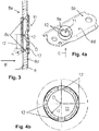
- a first step St1 a preferably cylindrical front cross tube 9 with an outer radius r1 and with a deformable end region 9b and the front link 8 with a bore 11, which has an inner radius r2 that is smaller than the outer radius r1 of the front cross tube 9, and with an at least partially circumferential beveled connecting part contact surface 8c and indentations 12 - as exemplified in FIG Fig. 3 shown - provided.
- the connecting part contact surface 8c is for example, bevelled by an angle ⁇ of between 50 ° and 70 °, in particular of approximately 60 °, with respect to the horizontal.
- a second step St2 the front cross tube 9 is inserted into the bore 11 of the front link 8 until the end region 9b projects through the bore 11. This takes place due to the differences in the radii r1, r2 due to the application of force and with deformation of the front cross tube 9 at least in the area of a surface 9c of the front cross tube 9 in which the surface 9c comes against the bore 11, so that the surface 9c of the front cross tube 9 at least partially adapts to the profile of the bore 11.
- the beveled cross tube contact surfaces 9a are formed on the surface 9c of the front cross tube 9, which are designed to be opposite to the connection part contact surfaces 8c which are beveled by the angle ⁇ .
- the surface 9c of the front cross tube 9 remains unaffected in this area depending on the depth of the indentations 12. This ensures that the front cross tube 9 can not be rotated in the bore 11 and thus against the front link 8.
- the front cross tube 9 is inserted, for example, until a certain amount of force is required to insert the front cross tube 9 deeper and thus further deform it. Furthermore, the insertion can be limited by the fact that a sufficiently large part of the front cross tube 9 projects through the bore 11 and the end region 9b of the front cross tube 9 is thus radially deformed outwards in a third step St3 can be that this can be placed on the rear of the handlebar 8d in order to clamp the front handlebar 8 between the deformed end region 9b and the pipe connection surface 9a.
- connection process and the front cross tube 9 is rotatably received on the front link 8.
- This type of connection with a cross tube can be used for all handlebars 8, 10 in Fig. 1 are also provided, for example, for the rear link 8 and the rear cross tube, not shown.
- such a connection between a cross tube and a handlebar or a fitting or a bottle can also be provided in an inclination adjustment device of the backrest 3, which connection can take place in an identical manner and with which torsional resistance and secure holding in this inclination adjustment device can also be achieved.
Landscapes
- Engineering & Computer Science (AREA)
- Mechanical Engineering (AREA)
- Aviation & Aerospace Engineering (AREA)
- Transportation (AREA)
- Seats For Vehicles (AREA)
- Chairs For Special Purposes, Such As Reclining Chairs (AREA)
- Steering Devices For Bicycles And Motorcycles (AREA)
Description
- Die Erfindung betrifft eine Verstellanordnung für eine Verstelleinrichtung eines Fahrzeugsitzes sowie ein Verfahren zum Herstellen einer derartigen Verstellanordnung.
- Verstelleinrichtungen für Fahrzeugsitze, beispielsweise Neigungsverstelleinrichtungen einer Rückenlehne oder Höhenverstelleinrichtungen für den gesamten Fahrzeugsitz, weisen herkömmlicherweise an Rahmenstrukturen gelagerte Querrohre auf, die verdrehfest mit Verbindungsteilen, beispielsweise Lenkern, Flanschen oder Beschlägen verbunden sind. Über die Verbindungsteile kann eine Drehbewegung oder eine Schwenkbewegung auf das Querrohr übertragen werden und/oder das Querrohr überträgt eine Drehbewegung auf die Verbindungsteile, um wiederum über die Verbindungsteile einen bestimmten Verstellmechanismus mittelbar oder unmittelbar betätigen zu können. Dabei ist beispielsweise auf beiden Seiten des Querrohres ein derartiges Verbindungsteil verdrehfest angeordnet, um eine Schwenkbewegung beidseitig auf den entsprechenden Verstellmechanismus am Fahrzeugsitz bzw. an der jeweiligen Fahrzeugsitz-Komponente übertragen zu können und somit für eine optimierte Verstellung zu sorgen.
- Eine Verbindung zwischen einem Querrohr und einem Verbindungsteil in Form eines Sitzseitenteils ist beispielsweise in
DE 10 2015 206 461 A1 beschrieben, wonach das Querrohr in eine Bohrung des Sitzseitenteils eingesteckt wird. Für eine axiale Festlegung des Querrohrs in der Bohrung wird am Querrohr insbesondere eine innere Wulst ausgebildet. Die innere Wulst wird hierbei in einem vorab durchgeführten Umformvorgang in das Querrohr eingebracht, so dass sich ein Außenradius des Querrohres ergibt, der größer ist als ein Innenradius der Bohrung. Dadurch wird bewirkt, dass das Querrohr nicht tiefer in die Bohrung eingesteckt werden kann. Eine axiale Festlegung in der anderen Richtung wird dadurch erreicht, dass nach dem Einstecken des Querrohres in die Bohrung ein Endbereich des Querrohres derartig radial nach außen umgeformt wird, dass das Querrohr nicht mehr aus der Bohrung entnommen werden kann, da der Endbereich dann einen Radius aufweist, der ebenfalls größer ist als der Innenradius der Bohrung. - Nachteilig hierbei ist, dass insbesondere im Crashfall auf die innere Wulst sehr hohe Verformungs- und Verspannungs-Kräfte wirken, wodurch eine dauerhafte und zuverlässige Verbindung zwischen dem Querrohr und dem Verbindungsteil, hier dem Sitzseitenteil, nicht gewährleistet werden kann. Zudem ist die Montage sehr aufwändig und durch das Ausbilden der inneren Wulst ist ein entsprechender Materialüberschuss für das Querrohr einzuplanen.
- Eine weitere Verbindung eines Querrohres mit einem Verbindungsteil ist in der gattungsfremden
EP 2 446 980 B1 gezeigt, die beschreibt, ein Gerüstrohr an einem als Grundplatte ausgeführten Verbindungsteil zu fixieren. Demnach ist vorgesehen, in dem Querrohr einen Doppelfalz mit aneinanderliegenden Falzlagen auszubilden, so dass sich ein Außenradius des Querrohres vergrößert. Bei Einstecken des Querrohres in eine Bohrung in der Grundplatte gelangt ab einer gewissen Einstecktiefe der Doppelfalz an die Grundplatte und verhindert ein tieferes Einstecken, da der Innenradius der Bohrung kleiner ist als der Außenradius des Doppelfalzes. In diesem Zustand wird ein Endbereich des eingesteckten Querrohres radial nach außen umgeformt und an die Grundplatte angelegt, so dass die Grundplatte zwischen dem umgeformten Endbereich und dem Doppelfalz quasi eingeklemmt wird. - Nachteilig ist auch hierbei, dass der Doppelfalz im Belastungfall hohen Verformungs- und Verspannungs-Kräften ausgesetzt ist, die unter Umständen eine Verformung verursachen, so dass eine Verbindung zur Grundplatte nicht dauerhaft sichergestellt werden kann. Zudem ist zum Ausbilden des Doppelfalzes ein Materialüberschuss am Querrohr einzuplanen. Auch die Herstellung der Verbindung zwischen beiden Bauteilen ist aufwändig.
-
DE 10 2013 009 847 A1 zeigt eine Verstellanordnung für eine Verstelleinrichtung eines Fahrzeugsitzes zum Verstellen einer Fahrzeugsitz-Komponente mit einem Querrohr und zumindest einem mit dem Querrohr verdrehfest verbundenen Verbindungsteil, das als Flansch ausgeführt ist, wobei bei einer Verdrehung des Querrohres eine Verstellung der Fahrzeugsitz-Komponente bewirkt werden kann, wobei das Querrohr zur verdrehfesten Befestigung mit dem Verbindungsteil in eine Bohrung im Verbindungsteil eingesteckt ist. Zum Ausbilden der verdrehfesten Verbindung werden in einem Umformvorgang ein Kragen und eine Endscheibe als umgeformter Endbereich hergestellt zwischen denen der Flansch eingeklemmt wird. -
EP 0 143 062 zeigt weiterhin ein Herstellungsverfahren, in dem zunächst ein Querrohr mit einem Außenradius und mit einem umformbaren Endbereich sowie ein Verbindungsteil bzw. eine Platte oder ein Stutzen mit einer Bohrung, die einen Innenradius aufweist, wobei der Innenradius der Bohrung geringer ist als der Außenradius des Querrohres, und mit einer um einen Winkel abgeschrägten Verbindungsteil-Anlagefläche, bereitgestellt werden. Weiterhin wird das Querrohr entlang einer Einsteckrichtung in die Bohrung in dem Verbindungsteil unter Verformung einer Oberfläche des Querrohres derartig eingesteckt, dass sich aufgrund des Unterschiedes in den Radien auf der Oberfläche des Querrohres eine Querrohr-Anlagefläche ausbildet, die gegensätzlich zu der Verbindungsteil-Anlagefläche abgeschrägt ist. Durch dieses Einstecken des Querrohres in die Bohrung unter Krafteinwirkung wird eine Verbindung zwischen beiden Bauteilen ausgebildet. - Es ist Aufgabe der Erfindung, eine Verstellanordnung für eine Verstelleinrichtung eines Fahrzeugsitzes bereitzustellen, die auch unter Belastung sicher und zuverlässig eingesetzt und die zudem mit wenig Aufwand und wenig Kosten ausgebildet werden kann. Zudem ist Aufgabe der Erfindung, ein Verfahren zur Herstellung einer derartigen Verstellanordnung anzugeben.
- Diese Aufgabe wird durch eine Verstellanordnung nach Anspruch 1 sowie ein Verfahren nach Anspruch 9 gelöst. Bevorzugte Weiterbildungen sind in den Unteransprüchen angegeben.
- Erfindungsgemäß ist demnach vorgesehen, an einem Verbindungsteil einer Verstellanordnung, beispielsweise einem Lenker oder einem Flansch, im Bereich einer Bohrung, in die ein Querrohr der Verstellanordnung eingesteckt ist, eine um einen bestimmten Winkel abgeschrägte Verbindungsteil-Anlagefläche auszubilden, an der eine gegensätzlich abgeschrägte Querrohr-Anlagefläche des Querrohres anliegt, wobei dadurch eine axiale Bewegung des Querrohres in der Bohrung eingeschränkt wird. Zudem ist ein Endbereich des Querrohres auf einer Verbindungsteil-Rückseite des Verbindungsteiles derartig radial nach außen umgeformt, dass das Verbindungsteil zwischen der an der Verbindungsteil-Anlagefläche anliegenden Querrohr-Anlagefläche und dem nach außen umgeformten Endbereich eingeklemmt ist, so dass das Querrohr mit dem Verbindungsteil vorzugsweise verdrehfest verbunden ist.
- Dadurch wird bereits der Vorteil erreicht, dass die Verbindung zwischen dem Querrohr und dem Verbindungsteil nicht durch eine umgeformte Wulst ausgebildet wird. Durch das Zusammenwirken der Anlageflächen können im Gegensatz zu einer Wulst oder einem Doppelfalz höhere Kräfte abgefangen werden, so dass eine sichere und zuverlässige Verbindung auch bei hohen Belastungen gewährleistet werden kann. Zudem ist zum Ausbilden der Verbindung lediglich zusätzliches Material zum Umformen des Endbereiches einzuplanen. Dadurch können Materialkosten gespart werden und der Montageaufwand wird verringert, da neben dem Verformen des Endbereiches kein zusätzlicher Umformvorgang nötig ist.
- Gemäß einer bevorzugten Weiterbildung ist vorgesehen, dass an dem Verbindungsteil im Bereich der Bohrung mindestens eine Einbuchtung angeordnet ist, der eine Ausbuchtung am Querrohr derartig gegenübersteht, dass ein Verdrehen zwischen dem Querrohr und dem Verbindungsteil verhindert ist. D. h. die Ausbuchtung am Querrohr befindet sich in der Einbuchtung im Bereich der Bohrung und blockiert somit eine Drehung des Querrohres in der Bohrung. Vorteilhafterweise wird dadurch eine Verdrehfestigkeit verbessert, da diese Maßnahme die Klemmwirkung, die bereits für eine gewisse Verdrehfestigkeit sorgen kann, unterstützt.
- Gemäß einer vorteilhaften Weiterbildung ist vorgesehen, dass vier Einbuchtungen vorgesehen sind, die 90° versetzt zueinander im Bereich der Bohrung angeordnet sind. Dadurch kann die Verdrehfestigkeit auch bei sehr hohen Belastungen sichergestellt werden.
- Vorzugsweise ist weiterhin vorgesehen, dass die Ausbuchtungen am Querrohr durch zumindest teilweise Verformung einer Oberfläche des Querrohres im Bereich der Ausbuchtungen und/oder durch zumindest teilweise Verformung einer Oberfläche des Querrohres im Bereich neben den Ausbuchtungen ausbildbar sind.
- Dadurch kann vorteilhafterweise erreicht werden, dass die Ausbuchtungen während eines Verbindungsvorganges ausgebildet werden können, bei dem das Querrohr in die Bohrung am Verbindungsteil eingesteckt wird. Dadurch, dass ein Außenradius des Querrohres im ursprünglichen Zustand vor dem Einstecken zumindest bereichsweise größer ist als ein Innenradius der Bohrung, wird die Oberfläche des Querrohres beim Einstecken unter einer Krafteinwirkung an das Profil der Bohrung angepasst. Da die Bohrung eine Einbuchtung aufweist, wird die Oberfläche des Querrohres beim Verbindungsvorgang also derartig verformt, dass zumindest eine zur Einbuchtung gegensätzlich geformte Ausbuchtung am Querprofil ausgebildet wird. Dies erfolgt entweder dadurch, dass in gewissen Bereichen der Außenradius des Querrohres verringert wird und dadurch eine Ausbuchtung dazwischen bleibt oder aber dadurch, dass das Querrohr auch im Bereich der Ausbuchtung selbst zumindest zu einem geringen Teil verformt wird.
- Dadurch kann vorteilhafterweise erreicht werden, dass zum Ausbilden einer Verdrehfestigkeit vorab keine zusätzlichen Ausbuchtungen oder ähnliche Elemente am Querrohr herzustellen sind und somit eine zusätzliche Umformung entfallen kann. Dadurch kann der Herstellungsaufwand minimiert werden, da lediglich ein Querrohr bereitzustellen ist, das vorzugsweise eine geringere Härte aufweist als das Verbindungsteil bzw. der Bereich der Bohrung am Verbindungsteil, so dass sich das Querrohr dem Profil der Bohrung anpassen kann, ohne die Bohrung selbst zu beschädigen.
- Gemäß einer vorteilhaften Weiterbildung ist weiterhin vorgesehen, dass analog zu den Ausbuchtungen am Querrohr auch die abgeschrägte Querrohr-Anlagefläche durch eine Verformung der Oberfläche des Querrohres ausbildbar ist. D.h. auch hier kann die Querrohr-Anlagefläche auch erst während des Verbindungsvorganges ausgebildet werden, indem aufgrund der unterschiedlichen Radien der Bohrung und des Querrohres eine Verformung der Oberfläche des Querrohres durch die Verbindungsteil-Anlagefläche erfolgt. Durch das Einstecken des Querrohres in die Bohrung unter Krafteinwirkung wird demnach erreicht, dass eine gegensätzlich abgeschrägte Querrohr-Anlagefläche ausgebildet wird, so dass die erfindungsgemäße Klemmwirkung ohne großen Montageaufwand und mit nur wenig Montageschritten und ohne vorherige Umformung des Querrohres ausgebildet werden kann.
- Gemäß einer vorteilhaften Weiterbildung ist vorgesehen, dass die abgeschrägte Verbindungsteil-Anlagefläche am Verbindungsteil um einen Winkel von zwischen 50° und 70°, insbesondere 60°, abgeschrägt ist. Dadurch kann eine besonders wirkungsvolle Kraftübertragung vom Querrohr in das Verbindungsteil gewährleistet werden. Gleichzeitig ist beim Verbindungsvorgang nur eine geringe Krafteinwirkung zur Verformung des Querrohres, durch die die Querrohr-Anlagefläche ausgebildet wird, nötig.
- Gemäß einer bevorzugten Weiterbildung ist weiterhin vorgesehen, dass der umgeformte Endbereich zum Ausbilden der Klemmwirkung an einer Verbindungsteil-Rückseite des Verbindungsteils anliegt, so dass keine zusätzlichen Elemente erforderlich sind, die für die Klemmwirkung sorgen.
- Vorzugsweise ist die Verstellanordnung hierbei Teil einer Verstelleinrichtung für einen Fahrzeugsitz, beispielsweise einer Höhenverstelleinrichtung des Fahrzeugsitzes oder einer Neigungsverstellung einer Rückenlehne. Gemäß einer bevorzugten Ausbildung ist das Querrohr der erfindungsgemäßen Verstellanordnung hierbei das vordere Querrohr einer Höhenverstelleinrichtung, wobei die Verstellanordnung in dem Fall für ein Anheben und Absenken des Sitzteils im vorderen Bereich sorgt und als Verbindungsteile demnach die vorderen Lenker der Höhenverstelleinrichtung dienen. Grundsätzlich kann das Querrohr entsprechend angepasst aber auch das hintere Querrohr der Höhenverstelleinrichtung sein, das dementsprechend hintere Lenker als Verbindungsteile aufweist, über die eine Betätigung einer Betätigungsvorrichtung, z.B. über ein Zahnkranz, übertragen wird.
- Zum Herstellen einer derartigen Verstellanordnung ist somit erfindungsgemäß vorgesehen, zunächst ein Querrohr mit einem Außenradius und mit einem umformbaren Endbereich sowie ein Verbindungsteil mit einer Bohrung, die einen Innenradius aufweist, der geringer ist als der Außenradius des Querrohres, und mit einer um einen Winkel abgeschrägten Verbindungsteil-Anlagefläche bereitzustellen.
- Anschließend wird das Querrohr entlang einer Einsteckrichtung in die Bohrung in dem Verbindungsteil unter Verformung der Oberfläche des Querrohres derartig eingesteckt, dass sich aufgrund des Unterschiedes in den Radien auf der Oberfläche des Querrohres eine Querrohr-Anlagefläche ausbildet, die gegensätzlich zu der Verbindungsteil-Anlagefläche abgeschrägt ist. Das Einstecken erfolgt, bis zumindest der Endbereich aus der Bohrung an einer Verbindungsteil-Rückseite herausragt.
- Anschließend ist ein Umformen des Endbereiches des Querrohres derartig vorgesehen, dass das Verbindungsteil im Bereich der Bohrung zwischen der Querrohr-Anlagefläche und dem umgeformten Endbereich eingeklemmt wird, so dass das Querrohr vorzugsweise verdrehfest mit dem Verbindungsteil verbunden wird.
- Somit kann in einfacher Weise eine sichere und zuverlässige Verbindung ausgebildet werden, wobei die relevanten Umformvorgänge direkt während der Verbindung ausgeführt werden können, ohne dass dabei eine Kraftübertragung über eine Wulst oder einen Falz vorliegt.
- Dadurch, dass das Umformen direkt über die Bohrung erfolgt, in der das Querrohr auch tatsächlich befestigt ist, können Klappergeräusche beim Einstellen der Sitzhöhe oder der Sitzneigung vermieden werden, da eine Umformung nur in tatsächlich benötigtem Maße erfolgt. Durch die abgeschrägten Anlageflächen kann eine unerwünschte Geräuschunterdrückung also vorteilhafterweise unterstützt werden.
- Die Erfindung wird im Folgenden anhand von einigen Ausführungsbeispielen näher erläutert. Es zeigen:
- Fig. 1
- eine schematische Ansicht eines Fahrzeugsitzes;
- Fig. 2a, 2b
- Detailansichten der Verbindung zwischen einem vorderen Querrohr und einem vorderen Lenker;
- Fig. 3
- eine Schnittansicht des vorderen Lenkers im Bereich einer Bohrung;
- Fig. 4a
- eine perspektivische Ansicht des vorderen Lenkers; und
- Fig. 4b
- eine Schnittansicht der Bohrung.
- Gemäß
Fig. 1 ist ein Fahrzeugsitz 1 dargestellt, der ein Sitzteil 2 und eine Rückenlehne 3 aufweist. Der Fahrzeugsitz 1 ist über Oberschienen 4 längsverstellbar am Fahrzeugboden 5 gelagert, wobei die Oberschienen 4 dazu in Unterschienen 6 verschiebbar aufgenommen sind. Darüber hinaus ist der Fahrzeugsitz 1 gemäß diesem Ausführungsbeispiel mit einer Höhenverstelleinrichtung ausgestattet. Zur Höhenverstellung des Kraftfahrzeugsitzes 1 ist an einer Sitzseite eine nicht dargestellte Höhenverstellpumpe vorgesehen, die über einen Bedienhebel 7 betätigt wird. Die Höhenverstellpumpe weist ein Ritzel auf, welches in bekannter Weise mit einem Zahnsegment an einem hinteren Lenker 10, der hier als Verbindungsteil dient, kämmt, wobei der hintere Lenker 10 an einem oberen Ende mit einem nicht dargestellten hinteren Querrohr verdrehfest verbunden ist. Ein weiterer hinterer Lenker 10 ist in identischer Weise an dem anderen Ende des hinteren Querrohrs verdrehfest aufgenommen. - Durch eine entsprechende Pumpbewegung mit dem Bedienhebel 7 beaufschlagt das Ritzel der Höhenverstellpumpe das Zahnsegment des einen hinteren Lenkers 10, so dass dieser hintere Lenker 10 in die eine oder andere Richtung unter Verdrehung des hinteren Querrohres verschwenkt. Diese Schwenkbewegung wird über das hintere Querrohr auch auf den anderen hinteren Lenker 10 übertragen. Eine durch die Höhenverstellpumpe induzierte Schwenkbewegung wirkt somit gleichzeitig auf beide hintere Lenker 10, wodurch die Höhe des Sitzteils 2 gegenüber dem Fahrzeugboden 5 verstellt werden kann. Diese Ausbildung der Höhenverstelleinrichtung entspricht dem Stand der Technik, so dass es dazu keiner weiteren Erläuterungen bedarf.
- Ergänzend sind gemäß
Fig. 1 zwei vordere Lenker 8 als Verbindungsteile vorgesehen, die in entsprechender Weise über ein vorderes Querrohr 9 miteinander verdrehfest verbunden sind und durch eine Lagerung an den Oberschienen 4 und dem Sitzteilrahmen des Sitzteils 2 bei einer Betätigung des Bedienhebels 7 ebenfalls verschwenken, so dass der Fahrzeugsitz 1 insgesamt nach oben oder unten verstellt wird. Eine Detailansicht dazu ist insbesondere in denFiguren 2a und 2b dargestellt, die den vorderen Lenker 8 mit dem vorderen Querrohr 9 zeigen. Über das vordere Querrohr 9 werden die oberen Enden 8a der vorderen Lenker 8 jeweils in beliebiger Weise an einem nicht dargestellten Sitzteilrahmen des Sitzteils 2 verschwenkbar um eine Drehachse D gelagert. Über ein unteres Ende 8b der vorderen Lenker 8 sind diese weiterhin jeweils an der Oberschiene 4 verschwenkbar gelagert. - Um eine verdrehfeste Verbindung zwischen dem vorderen Querrohr 9 und den beiden vorderen Lenkern 8 auszubilden und dadurch eine Verstellanordnung 100 bereitzustellen, die Teil der jeweiligen Verstelleinrichtung ist, ist das vordere Querrohr 9, das einen Außenradius r1 aufweist, durch eine Bohrung 11 im oberen Ende 8a des vorderen Lenkers 8, die einen Innenradius r2 aufweist, eingesteckt, wobei der Außenradius r1 größer ist als der Innenradius r2. Beispielhaft wird dies im Folgenden für einen der vorderen Lenker 8 näher erläutert:
Eine axiale Beweglichkeit des vorderen Querrohres 9 gegen den vorderen Lenker 8 entlang der Drehachse D ist demnach dadurch begrenzt, dass das vordere Querrohr 9 im Bereich der Bohrung 11 mit einer abgeschrägten Querrohr-Anlagefläche 9a an einer Verbindungsteil-Anlagefläche 8c am vorderen Lenker 8 zumindest teilweise anliegt und sich darauf abstützt. Dadurch wird die axiale Bewegung des vorderen Querrohres 9 entlang einer Einsteckrichtung E begrenzt, da die Verbindungsteil-Anlagefläche 8c ein weiteres Einstecken entlang der Einsteckrichtung E zumindest ohne das Ausüben einer hohen Kraft blockiert. - Um auch eine axiale Bewegung des vorderen Querrohres 9 entgegen der Einsteckrichtung E zu verhindern, ist das vordere Querrohr 9 in einem Endbereich 9b radial nach außen umlaufend auf eine Lenker-Rückseite 8d (Verbindungsteil-Rückseite) umgebogen. Somit wird das vordere Querrohr 9 durch das Zusammenwirken der abgeschrägten Anlageflächen 9a, 8c sowie dem umgebogenen Endbereich 9b des vorderen Querrohres 9 am vorderen Lenker 8 gehalten bzw. der vordere Lenker 8 dadurch vom Querrohr 9 eingeklemmt. Aufgrund des zumindest teilweise umlaufenden Anliegens der beiden Anlageflächen 9a, 8c wird auch eine radiale Bewegung senkrecht zur Drehachse D verhindert.
- Eine Verdrehfestigkeit des vorderen Querrohres 9 gegenüber dem vorderen Lenker 8 kann nur bis zu einem gewissen Grad durch das oben beschriebene Einklemmen ausgebildet werden. Um dies zu unterstützen, sind gemäß den Figuren
Fig. 3, 4a und 4b weiterhin vier im Bereich der Bohrung 11 eingebrachte Einbuchtungen 12, die um 90° versetzt zueinander angeordnet sind, vorgesehen. In diesen Einbuchtungen 12 liegt das vordere Querrohr 9 mit Ausbuchtungen 13, die andeutungsweise inFig. 2b zu erkennen sind, an, wobei die Ausbuchtungen 13 im vorderen Querrohr 9 in einem Verbindungsvorgang des vorderen Querrohres 9 mit dem vorderen Lenker 8 ausgebildet werden. Das vordere Querrohr 9 liegt also im Bereich der Bohrung 11 idealerweise vollständig umlaufend an dem vorderen Lenker 8 an, indem die Querrohr-Anlagefläche 9a an der Verbindungsteil-Anlagefläche 8c flächig und dazwischen um 90° versetzt die vier Ausbuchtungen 13 am vorderen Querrohr 9 an den vier Einbuchtungen 12 der Bohrung 11 anliegen. Dadurch kann letztlich das vordere Querrohr 9 nicht mehr gegen den vorderen Lenker 8 verdreht werden. Somit kann eine Bewegungseinschränkung des vorderen Querrohres 9 gegenüber dem vorderen Lenker 8 in alle Richtungen ausgebildet werden. - In einem erfindungsgemäßen Verbindungsvorgang zum Ausbilden der Verbindung zwischen dem vorderen Querrohr 9 und dem jeweiligen vorderen Lenker 8, d.h. zum Ausbilden der Verstellanordnung 100, können beispielsweise die folgenden Schritte vorgesehen sein:
In einem ersten Schritt St1 werden ein vorzugsweise zylindrisches vorderes Querrohr 9 mit einem Außenradius r1 und mit einem umformbaren Endbereich 9b sowie der vordere Lenker 8 mit einer Bohrung 11, die einen Innenradius r2 aufweist, der geringer ist als der Außenradius r1 des vorderen Querrohres 9, und mit einer zumindest teilweise umlaufenden abgeschrägten Verbindungsteil-Anlagefläche 8c sowie Einbuchtungen 12 - wie beispielhaft inFig. 3 dargestellt - bereitgestellt. Die Verbindungsteil-Anlagefläche 8c ist beispielsweise um einen Winkel α von zwischen 50° und 70°, insbesondere von ca. 60° gegenüber der Horizontalen abgeschrägt. - In einem zweiten Schritt St2 wird das vordere Querrohr 9 in die Bohrung 11 des vorderen Lenkers 8 eingesteckt, bis der Endbereich 9b durch die Bohrung 11 hindurchragt. Dies erfolgt aufgrund der Unterschiede in den Radien r1, r2 durch eine Krafteinwirkung sowie unter Verformung des vorderen Querrohres 9 zumindest in dem Bereich einer Oberfläche 9c des vorderen Querrohres 9, in dem die Oberfläche 9c gegen die Bohrung 11 gelangt, so dass sich die Oberfläche 9c des vorderen Querrohrs 9 an das Profil der Bohrung 11 zumindest teilweise anpasst.
- Demnach werden an der Oberfläche 9c des vorderen Querohres 9 die abgeschrägten Querrohr-Anlageflächen 9a ausgebildet, die gegensätzlich abgeschrägt zu den um den Winkel α angeschrägten Verbindungsteil-Anlageflächen 8c ausgebildet sind. Im Bereich der Einbuchtungen 12 in der Bohrung 11 findet eine weniger starke Verformung der Oberfläche 9c des vorderen Querrohres 9 statt, da der Innenradius r2 der Bohrung 11 im Bereich der Einbuchtungen 12 weniger stark von dem Außenradius r1 des vorderen Querrohres 9 abweicht. Unter Umständen bleibt die Oberfläche 9c des vorderen Querrohres 9 in diesem Bereich je nach Tiefe der Einbuchtungen 12 auch unbeeinflusst. Dadurch wird gewährleistet, dass das vordere Querrohr 9 nicht in der Bohrung 11 und somit gegen den vorderen Lenker 8 verdreht werden kann.
- Das Einstecken des vorderen Querrohres 9 erfolgt beispielsweise bis ein gewisser Kraftaufwand nötig ist, um das vordere Querrohr 9 tiefer einzustecken und somit weiter zu verformen. Weiterhin kann das Einstecken dadurch begrenzt sein, dass ein genügend großer Teil des vorderen Querrohres 9 durch die Bohrung 11 ragt und der Endbereich 9b des vorderen Querrohres 9 somit in einem dritten Schritt St3 derartig radial nach außen umgeformt werden kann, dass sich dieses an die Lenker-Rückseite 8d anlegen lässt, um den vorderen Lenker 8 quasi zwischen dem umgeformten Endbereich 9b und der Rohr-Verbindungsfläche 9a einzuklemmen.
- Damit ist der Verbindungsvorgang abgeschlossen und das vordere Querrohr 9 ist verdrehfest am vorderen Lenker 8 aufgenommen. Diese Art der Verbindung mit einem Querrohr kann für alle Lenker 8, 10, die in
Fig. 1 dargestellt sind, vorgesehen sein also beispielsweise auch für die hinteren Lenker 8 und das nicht dargestellte hintere Querrohr. Ergänzend kann auch in einer Neigungsverstelleinrichtung der Rückenlehne 3 eine derartige Verbindung zwischen einem Querrohr und einem Lenker oder einem Beschlag oder einem Flasch vorgesehen sein, die in identischer Weise erfolgen kann und mit der ebenfalls eine Verdrehfestigkeit und ein sicheres Halten in dieser Neigungsverstelleinrichtung erreicht werden kann. -
- 1
- Fahrzeugsitz
- 2
- Sitzteil
- 3
- Rückenlehne
- 4
- Oberschiene
- 5
- Fahrzeugboden
- 6
- Unterschiene
- 7
- Bedienhebel
- 8
- vorderer Lenker/Verbindungsteil
- 8a
- oberes Ende des vorderen Lenkers 8
- 8b
- unteres Ende des vorderen Lenkers 8
- 8c
- Verbindungsteil-Anlagefläche
- 8d
- Lenker-Rückseite/Verbindungsteil-Rückseite
- 9
- vorderes Querrohr
- 9a
- Querrohr-Anlagefläche
- 9b
- Endbereich
- 9c
- Oberfläche des vorderen Querrohres 9
- 10
- hinterer Lenker/Verbindungsteil
- 11
- Bohrung
- 12
- Einbuchtungen
- 13
- Ausbuchtungen
- 100
- Verstellanordnung
- D
- Drehachse
- E
- Einsteckrichtung
- r1
- Außenradius des vorderen Querrohres
- r2
- Innenradius der Bohrung 11
Claims (11)
- Verstellanordnung (100) für eine Verstelleinrichtung eines Fahrzeugsitzes (1) zum Verstellen einer Fahrzeugsitz-Komponente (2, 3), aufweisend ein Querrohr (9) und zumindest ein mit dem Querrohr (9) verdrehfest verbundenes Verbindungsteil (8, 10), wobei bei einer Verdrehung des Querrohres (9) eine Verstellung der Fahrzeugsitz-Komponente (2, 3) bewirkt werden kann, wobei das Querrohr (9) zur verdrehfesten Befestigung mit dem Verbindungsteil (8, 10) in eine Bohrung (11) im Verbindungsteil (8, 10) eingesteckt ist,
dadurch gekennzeichnet, dass
an dem Verbindungsteil (8) im Bereich der Bohrung (11) eine um einen Winkel (α) abgeschrägte Verbindungsteil-Anlagefläche (8c) ausgebildet ist, an der eine gegensätzlich abgeschrägte Querrohr-Anlagefläche (9a) des Querrohres (9) anliegt zum Einschränken einer axialen Bewegung des Querrohres (9), und
ein Endbereich (9b) des Querrohres (9) auf einer Verbindungsteil-Rückseite (8d) des Verbindungsteiles (8) derartig radial nach außen umgeformt ist, dass das Verbindungsteil (8) zwischen der an der abgeschrägten Verbindungsteil-Anlagefläche (8c) anliegenden gegensätzlich abgeschrägten Querrohr-Anlagefläche (9a) und dem nach außen umgeformten Endbereich (9b) eingeklemmt ist. - Verstellanordnung (100) nach Anspruch 1, dadurch gekennzeichnet, dass an dem Verbindungsteil (8) im Bereich der Bohrung (11) mindestens eine Einbuchtung (12) angeordnet ist, der eine Ausbuchtung (13) am Querrohr (9) derartig gegenübersteht, dass ein Verdrehen zwischen dem Querrohr (9) und dem Verbindungsteil (8) verhindert ist.
- Verstellanordnung (100) nach Anspruch 2, dadurch gekennzeichnet, dass vier Einbuchtungen (12) vorgesehen sind, die 90° versetzt zueinander im Bereich der Bohrung (11) angeordnet sind.
- Verstellanordnung (100) nach Anspruch 2 oder 3, dadurch gekennzeichnet, dass die Ausbuchtungen (13) am Querrohr (9) durch zumindest teilweise Verformung einer Oberfläche (9c) des Querrohres (9) im Bereich der Ausbuchtungen (13) und/oder durch zumindest teilweise Verformung einer Oberfläche (9c) des Querrohres (9) im Bereich neben den Ausbuchtungen (13) ausbildbar sind.
- Verstellanordnung (100) nach einem der vorhergehenden Ansprüche, dadurch gekennzeichnet, dass die Querrohr-Anlagefläche (9a) durch eine Verformung einer Oberfläche (9c) des Querrohres (9) ausbildbar ist.
- Verstellanordnung (100) nach Anspruch 4 oder 5, dadurch gekennzeichnet, dass die Ausbuchtungen (13) und/oder die Querrohr-Anlagefläche (9a) am Querrohr (9) während eines Verbindungsvorganges dadurch ausbildbar sind, dass das Querrohr (9) einen Außenradius (r1) aufweist, der zumindest bereichsweise größer ist als ein Innenradius (r2) der Bohrung (11), so dass sich die Oberfläche (9c) des Querrohres (9) beim Verbindungsvorgang durch ein Einstecken des Querrohres (9) in die Bohrung (11) derartig verformt, dass gegensätzlich zu den Einbuchtungen (12) die Ausbuchtungen (13) und/oder gegensätzlich zu der Verbindungs-Anlagefläche (8c) die Querrohr-Anlagefläche (9a) ausgebildet wird.
- Verstellanordnung (100) nach einem der vorhergehenden Ansprüche, dadurch gekennzeichnet, dass die abgeschrägte Verbindungsteil-Anlagefläche (8c) am Verbindungsteil (8) um einen Winkel (α) von zwischen 50° und 70°, vorzugsweise 60° abgeschrägt ist.
- Verstellanordnung (100) nach einem der vorhergehenden Ansprüche, dadurch gekennzeichnet, dass der umgeformte Endbereich (9b) an einer Verbindungsteil-Rückseite (8d) des Verbindungsteils (8) anliegt.
- Verfahren zum Herstellen einer Verstellanordnung (100), insbesondere einer Verstellanordnung (100) nach einem der vorhergehenden Ansprüche, mit mindestens den folgenden Schritten:- Bereitstellen eines Querrohrs (9) mit einem Außenradius (r1) und mit einem umformbaren Endbereich (9b) sowie eines Verbindungsteils (8) mit einer Bohrung (11), die einen Innenradius (r2) aufweist, der geringer ist als der Außenradius (r1) des Querrohres (9), und mit einer um einen Winkel (α) abgeschrägten Verbindungsteil-Anlagefläche (8c) (St1);- Einstecken des Querrohres (9) entlang einer Einsteckrichtung (E) in die Bohrung (11) in dem Verbindungsteil (8) unter Verformung einer Oberfläche (9c) des Querrohres (3) derartig, dass sich aufgrund des Unterschiedes in den Radien (r1, r2) auf der Oberfläche (9c) des Querrohres (9) eine Querrohr-Anlagefläche (9a) ausbildet, die gegensätzlich zu der Verbindungsteil-Anlagefläche (8c) abgeschrägt ist,
dadurch gekennzeichnet, dass
das Querrohr (9) zumindest bis dann in die Bohrung (11) eingesteckt wird, bis der Endbereich (9b) aus der Bohrung (11) an einer Verbindungsteil-Rückseite (8d) herausragt (St2); und- Umformen des Endbereiches (9b) des Querrohres (9) derartig, dass das Verbindungsteil (8) zwischen der Querrohr-Anlagefläche (9a) und dem umgeformten Endbereich (9b) eingeklemmt wird, so dass das Querrohr (9) verdrehfest mit dem Verbindungsteil (8) verbunden wird (St3). - Verfahren nach Anspruch 9, dadurch gekennzeichnet, dass an dem bereitgestellten Verbindungsteil (8) im Bereich der Bohrung (11) weiterhin mindestens eine Einbuchtung (12) angeordnet ist, durch die beim Einstecken des Querrohres (9) in die Bohrung (11) am Querrohr (9) durch zumindest teilweise Verformung der Oberfläche (9c) des Querrohres (9) Ausbuchtungen (13) ausbildet werden, die zumindest bereichsweise gegensätzlich zu den Einbuchtungen (12) ausgeführt sind, wobei dazu die Oberfläche (9c) im Bereich der Ausbuchtungen (13) und/oder im Bereich neben den Ausbuchtungen (13) verformt wird.
- Fahrzeugsitz (1) mit einer Verstellanordnung (100) nach einem der Ansprüche 1 bis 8 für eine Verstelleinrichtung, vorzugsweise eine Höhenverstelleinrichtung oder eine Neigungsverstelleinrichtung, hergestellt insbesondere durch ein Verfahren nach Anspruch 9 oder 10.
Applications Claiming Priority (1)
| Application Number | Priority Date | Filing Date | Title |
|---|---|---|---|
| DE102017108206.9A DE102017108206B4 (de) | 2017-04-18 | 2017-04-18 | Verstellanordnung für eine Verstelleinrichtung eines Fahrzeugsitzes, Verfahren zum Herstellen einer derartigen Verstellanordnung sowie Fahrzeugsitz |
Publications (2)
| Publication Number | Publication Date |
|---|---|
| EP3392081A1 EP3392081A1 (de) | 2018-10-24 |
| EP3392081B1 true EP3392081B1 (de) | 2020-05-27 |
Family
ID=61557107
Family Applications (1)
| Application Number | Title | Priority Date | Filing Date |
|---|---|---|---|
| EP18159543.0A Active EP3392081B1 (de) | 2017-04-18 | 2018-03-01 | Verstellanordnung für eine verstelleinrichtung eines fahrzeugsitzes sowie ein verfahren zum herstellen einer derartigen verstellanordnung |
Country Status (5)
| Country | Link |
|---|---|
| US (1) | US11148559B2 (de) |
| EP (1) | EP3392081B1 (de) |
| JP (1) | JP6587367B2 (de) |
| CN (1) | CN108725270B (de) |
| DE (1) | DE102017108206B4 (de) |
Families Citing this family (6)
| Publication number | Priority date | Publication date | Assignee | Title |
|---|---|---|---|---|
| DE102017108218B4 (de) * | 2017-04-18 | 2020-12-24 | Faurecia Autositze Gmbh | Höhenverstelleinrichtung eines Kraftfahrzeugsitzes sowie Verfahren zur Herstellung einer derartigen Höhenverstelleinrichtung |
| FR3088899B1 (fr) * | 2018-11-26 | 2022-03-18 | Zodiac Seats France | Procede d'assemblage entre une poutre et un element structurel d'un siege d'avion |
| CN109692905B (zh) * | 2019-02-28 | 2020-07-28 | 重庆延锋安道拓锋奥汽车部件系统有限公司 | 座椅高调传动件成型模具 |
| DE102019118255A1 (de) | 2019-07-05 | 2021-01-07 | Faurecia Autositze Gmbh | Fahrzeugsitz-Strukturbauteil, Fahrzeugsitz und Verfahren zur Herstellung eines Fahrzeugsitz-Strukturbauteils |
| DE102019118258A1 (de) | 2019-07-05 | 2021-01-07 | Faurecia Autositze Gmbh | Fahrzeugsitz-Strukturbauteil und Fahrzeugsitz |
| KR102314614B1 (ko) * | 2021-03-31 | 2021-10-20 | 주식회사 다스 | 자동차용 시트의 리어링크 조립체와 그 제조 방법 |
Family Cites Families (22)
| Publication number | Priority date | Publication date | Assignee | Title |
|---|---|---|---|---|
| US1027835A (en) * | 1909-05-14 | 1912-05-28 | Henry P Gale | Metal pulley. |
| US3024300A (en) * | 1955-05-09 | 1962-03-06 | Rca Corp | Vacuum seal for electron tubes |
| US4233726A (en) * | 1978-12-21 | 1980-11-18 | Arvin Industries, Inc. | Method of joining a tube to a plate |
| FR2528132B1 (fr) * | 1982-06-03 | 1985-09-27 | Cegedur | Dispositif d'assemblage d'un tube et d'un element de tole |
| FR2553690B1 (fr) | 1983-10-21 | 1986-09-12 | Cegedur | Methode d'assemblage d'un tube mince dans une plaque ou un manchon |
| US4913268A (en) * | 1986-12-05 | 1990-04-03 | Ford Motor Company | Weldless automotive shock absorber |
| DE4341206A1 (de) * | 1993-12-03 | 1995-06-08 | Bayerische Motoren Werke Ag | An mindestens einem Wandungsteil befestigtes Aufnahmeteil |
| FR2735731B1 (fr) * | 1995-06-20 | 1997-08-29 | Irausa Ingeniera | Structure de siege de vehicule integrant une ceinture de securite |
| FR2772317A1 (fr) * | 1997-12-17 | 1999-06-18 | Faure Bertrand Equipements Sa | Siege de vehicule dote d'un mecanisme de rehausse, et son procede de fabrication |
| DE29909441U1 (de) * | 1999-05-29 | 1999-08-05 | Bertrand Faure Sitztechnik GmbH & Co. KG, 31655 Stadthagen | Kraftfahrzeug-Sitzteil |
| DE102004043688A1 (de) * | 2004-06-23 | 2006-04-06 | Profil-Verbindungstechnik Gmbh & Co. Kg | Verfahren zur Herstellung eines Zusammenbauteils bestehend aus einem Blechteil und einem an diesem angebrachten Funktionselement, Blechteil sowie Funktionselement |
| DE102005007716A1 (de) | 2005-02-18 | 2006-08-31 | Ulrich Huperz Schweißtechnik GmbH & Co.KG | Sitzhöhenverstellung |
| EP2027951A1 (de) | 2007-08-23 | 2009-02-25 | WAFIOS Aktiengesellschaft | Verfahren zum drehfesten Verbinden eines metallischen Rohres mit einem Blech sowie drehfeste Verbindung eines metallischen Rohres mit einem Blech |
| FR2942431B1 (fr) | 2009-02-20 | 2011-03-11 | Faurecia Sieges Automobile | Siege de vehicule, procede de fabrication d'un tel siege de vehicule et machine pour la mise en oeuvre du procede de fabrication. |
| CN201525302U (zh) * | 2009-09-27 | 2010-07-14 | 佛吉亚(上海)管理有限公司 | 用于电动座椅的钢管与冲压件的刚性连接结构 |
| DE102010049589B8 (de) | 2010-10-26 | 2012-09-13 | Welser Profile Austria Gmbh | Rohr und Verfahren zur Bearbeitung von Rohrenden |
| CN202491698U (zh) * | 2012-02-10 | 2012-10-17 | 比亚迪股份有限公司 | 一种座椅钢管与冲压件连接结构 |
| FR2992241B1 (fr) * | 2012-06-21 | 2014-07-18 | Faurecia Sieges Automobile | Procede de formage d'un tube metallique avec fixation sur un flasque et assemblage comprenant un tel tube |
| JP6324811B2 (ja) * | 2014-05-26 | 2018-05-16 | トヨタ紡織株式会社 | 乗物用シート |
| DE102015103228B4 (de) | 2015-03-05 | 2018-03-22 | Viega Technology Gmbh & Co. Kg | Presshülse, Pressfitting und Verwendung des Pressfittings oder der Presshülse |
| DE102015206461A1 (de) | 2015-04-10 | 2016-10-13 | Brose Fahrzeugteile Gmbh & Co. Kommanditgesellschaft, Coburg | Verfahren zur Umformung eines rohrförmigen Strukturbauteils für Kraftfahrzeugsitze |
| DE102015219497A1 (de) | 2015-10-08 | 2017-04-13 | Brose Fahrzeugteile Gmbh & Co. Kg, Coburg | Vorrichtung und Verfahren zum Verbinden eines rohrförmigen Strukturbauteils mit einem Anbauteil eines Kraftfahrzeugsitzes |
-
2017
- 2017-04-18 DE DE102017108206.9A patent/DE102017108206B4/de active Active
-
2018
- 2018-03-01 EP EP18159543.0A patent/EP3392081B1/de active Active
- 2018-04-09 US US15/947,950 patent/US11148559B2/en active Active
- 2018-04-17 JP JP2018078809A patent/JP6587367B2/ja active Active
- 2018-04-18 CN CN201810347915.8A patent/CN108725270B/zh active Active
Non-Patent Citations (1)
| Title |
|---|
| None * |
Also Published As
| Publication number | Publication date |
|---|---|
| US11148559B2 (en) | 2021-10-19 |
| JP6587367B2 (ja) | 2019-10-09 |
| US20180297492A1 (en) | 2018-10-18 |
| CN108725270B (zh) | 2022-03-18 |
| CN108725270A (zh) | 2018-11-02 |
| DE102017108206B4 (de) | 2020-06-18 |
| EP3392081A1 (de) | 2018-10-24 |
| JP2018177220A (ja) | 2018-11-15 |
| DE102017108206A1 (de) | 2018-10-18 |
Similar Documents
| Publication | Publication Date | Title |
|---|---|---|
| DE102017108206B4 (de) | Verstellanordnung für eine Verstelleinrichtung eines Fahrzeugsitzes, Verfahren zum Herstellen einer derartigen Verstellanordnung sowie Fahrzeugsitz | |
| DE102010012980B4 (de) | Beschlag für einen Fahrzeugsitz und Fahrzeugsitz | |
| DE10105282B4 (de) | Beschlag für einen Fahrzeugsitz | |
| DE102009012958B4 (de) | Schwenkgelenkanordnung und damit ausgerüstete Fahrzeugsitzrahmenordnung | |
| EP2376309B1 (de) | Fahrzeugsitz, insbesondere kraftfahrzeugsitz | |
| DE102014214896B4 (de) | Lehneneinsteller | |
| EP2566719B1 (de) | Beschlag für einen fahrzeugsitz | |
| DE102010013091B4 (de) | Verfahren zur Herstellung eines Fahrzeugsitz-Beschlags und Beschlag | |
| DE102012009173B4 (de) | Toleranzausgleichseinrichtung | |
| DE202009016989U1 (de) | Beschlag für einen Fahrzeugsitz | |
| EP1687176B1 (de) | Rastbeschlag für einen fahrzeugsitz | |
| DE102009041490A1 (de) | Beschlag für einen Fahrzeugsitz | |
| DE2526087A1 (de) | Sitz mit verriegelungsmechanismus | |
| EP2731850B1 (de) | Lenkritzel für ein lenksystem sowie verfahren zu dessen herstellung | |
| EP2934984B1 (de) | Lenksäule für ein kraftfahrzeug | |
| DE112016004619B4 (de) | Baugruppe eines Fahrzeugsitzes, die ein Rohrelement und ein daran angeordnetes Befestigungsteil umfasst | |
| DE102019118258A1 (de) | Fahrzeugsitz-Strukturbauteil und Fahrzeugsitz | |
| DE10021403C2 (de) | Neigungsverstellbeschlag für die Rückenlehne eines Kraftfahrzeugsitzes | |
| EP2048022B1 (de) | Fahrzeugsitz, insbesondere Kraftfahrzeugsitz | |
| WO2012019717A1 (de) | Beschlagsanordnung mit einem anschlag | |
| DE102010010925B4 (de) | Beschlag für einen Fahrzeugsitz und Fahrzeugsitz mit einem solchen Beschlag | |
| EP3392080B1 (de) | Höhenverstelleinrichtung eines kraftfahrzeugsitzes sowie verfahren zur herstellung einer derartigen höhenverstelleinrichtung | |
| DE69704202T2 (de) | Neigungsverstellungsmechanismus für einen Sitz | |
| DE202016106796U1 (de) | Fahrzeugsitz | |
| DE10019249A1 (de) | Fahrzeuglenksäule |
Legal Events
| Date | Code | Title | Description |
|---|---|---|---|
| PUAI | Public reference made under article 153(3) epc to a published international application that has entered the european phase |
Free format text: ORIGINAL CODE: 0009012 |
|
| STAA | Information on the status of an ep patent application or granted ep patent |
Free format text: STATUS: THE APPLICATION HAS BEEN PUBLISHED |
|
| AK | Designated contracting states |
Kind code of ref document: A1 Designated state(s): AL AT BE BG CH CY CZ DE DK EE ES FI FR GB GR HR HU IE IS IT LI LT LU LV MC MK MT NL NO PL PT RO RS SE SI SK SM TR |
|
| AX | Request for extension of the european patent |
Extension state: BA ME |
|
| STAA | Information on the status of an ep patent application or granted ep patent |
Free format text: STATUS: REQUEST FOR EXAMINATION WAS MADE |
|
| 17P | Request for examination filed |
Effective date: 20190215 |
|
| RBV | Designated contracting states (corrected) |
Designated state(s): AL AT BE BG CH CY CZ DE DK EE ES FI FR GB GR HR HU IE IS IT LI LT LU LV MC MK MT NL NO PL PT RO RS SE SI SK SM TR |
|
| RIC1 | Information provided on ipc code assigned before grant |
Ipc: B60N 2/68 20060101AFI20191126BHEP Ipc: B60N 2/02 20060101ALI20191126BHEP |
|
| GRAP | Despatch of communication of intention to grant a patent |
Free format text: ORIGINAL CODE: EPIDOSNIGR1 |
|
| STAA | Information on the status of an ep patent application or granted ep patent |
Free format text: STATUS: GRANT OF PATENT IS INTENDED |
|
| INTG | Intention to grant announced |
Effective date: 20200116 |
|
| GRAS | Grant fee paid |
Free format text: ORIGINAL CODE: EPIDOSNIGR3 |
|
| GRAA | (expected) grant |
Free format text: ORIGINAL CODE: 0009210 |
|
| STAA | Information on the status of an ep patent application or granted ep patent |
Free format text: STATUS: THE PATENT HAS BEEN GRANTED |
|
| AK | Designated contracting states |
Kind code of ref document: B1 Designated state(s): AL AT BE BG CH CY CZ DE DK EE ES FI FR GB GR HR HU IE IS IT LI LT LU LV MC MK MT NL NO PL PT RO RS SE SI SK SM TR |
|
| REG | Reference to a national code |
Ref country code: GB Ref legal event code: FG4D Free format text: NOT ENGLISH |
|
| REG | Reference to a national code |
Ref country code: CH Ref legal event code: EP |
|
| REG | Reference to a national code |
Ref country code: DE Ref legal event code: R096 Ref document number: 502018001506 Country of ref document: DE |
|
| REG | Reference to a national code |
Ref country code: AT Ref legal event code: REF Ref document number: 1274228 Country of ref document: AT Kind code of ref document: T Effective date: 20200615 |
|
| REG | Reference to a national code |
Ref country code: LT Ref legal event code: MG4D |
|
| PG25 | Lapsed in a contracting state [announced via postgrant information from national office to epo] |
Ref country code: SE Free format text: LAPSE BECAUSE OF FAILURE TO SUBMIT A TRANSLATION OF THE DESCRIPTION OR TO PAY THE FEE WITHIN THE PRESCRIBED TIME-LIMIT Effective date: 20200527 Ref country code: FI Free format text: LAPSE BECAUSE OF FAILURE TO SUBMIT A TRANSLATION OF THE DESCRIPTION OR TO PAY THE FEE WITHIN THE PRESCRIBED TIME-LIMIT Effective date: 20200527 Ref country code: PT Free format text: LAPSE BECAUSE OF FAILURE TO SUBMIT A TRANSLATION OF THE DESCRIPTION OR TO PAY THE FEE WITHIN THE PRESCRIBED TIME-LIMIT Effective date: 20200928 Ref country code: IS Free format text: LAPSE BECAUSE OF FAILURE TO SUBMIT A TRANSLATION OF THE DESCRIPTION OR TO PAY THE FEE WITHIN THE PRESCRIBED TIME-LIMIT Effective date: 20200927 Ref country code: NO Free format text: LAPSE BECAUSE OF FAILURE TO SUBMIT A TRANSLATION OF THE DESCRIPTION OR TO PAY THE FEE WITHIN THE PRESCRIBED TIME-LIMIT Effective date: 20200827 Ref country code: GR Free format text: LAPSE BECAUSE OF FAILURE TO SUBMIT A TRANSLATION OF THE DESCRIPTION OR TO PAY THE FEE WITHIN THE PRESCRIBED TIME-LIMIT Effective date: 20200828 Ref country code: LT Free format text: LAPSE BECAUSE OF FAILURE TO SUBMIT A TRANSLATION OF THE DESCRIPTION OR TO PAY THE FEE WITHIN THE PRESCRIBED TIME-LIMIT Effective date: 20200527 |
|
| REG | Reference to a national code |
Ref country code: NL Ref legal event code: MP Effective date: 20200527 |
|
| PG25 | Lapsed in a contracting state [announced via postgrant information from national office to epo] |
Ref country code: LV Free format text: LAPSE BECAUSE OF FAILURE TO SUBMIT A TRANSLATION OF THE DESCRIPTION OR TO PAY THE FEE WITHIN THE PRESCRIBED TIME-LIMIT Effective date: 20200527 Ref country code: RS Free format text: LAPSE BECAUSE OF FAILURE TO SUBMIT A TRANSLATION OF THE DESCRIPTION OR TO PAY THE FEE WITHIN THE PRESCRIBED TIME-LIMIT Effective date: 20200527 Ref country code: BG Free format text: LAPSE BECAUSE OF FAILURE TO SUBMIT A TRANSLATION OF THE DESCRIPTION OR TO PAY THE FEE WITHIN THE PRESCRIBED TIME-LIMIT Effective date: 20200827 Ref country code: HR Free format text: LAPSE BECAUSE OF FAILURE TO SUBMIT A TRANSLATION OF THE DESCRIPTION OR TO PAY THE FEE WITHIN THE PRESCRIBED TIME-LIMIT Effective date: 20200527 |
|
| PG25 | Lapsed in a contracting state [announced via postgrant information from national office to epo] |
Ref country code: NL Free format text: LAPSE BECAUSE OF FAILURE TO SUBMIT A TRANSLATION OF THE DESCRIPTION OR TO PAY THE FEE WITHIN THE PRESCRIBED TIME-LIMIT Effective date: 20200527 Ref country code: AL Free format text: LAPSE BECAUSE OF FAILURE TO SUBMIT A TRANSLATION OF THE DESCRIPTION OR TO PAY THE FEE WITHIN THE PRESCRIBED TIME-LIMIT Effective date: 20200527 |
|
| PG25 | Lapsed in a contracting state [announced via postgrant information from national office to epo] |
Ref country code: RO Free format text: LAPSE BECAUSE OF FAILURE TO SUBMIT A TRANSLATION OF THE DESCRIPTION OR TO PAY THE FEE WITHIN THE PRESCRIBED TIME-LIMIT Effective date: 20200527 Ref country code: IT Free format text: LAPSE BECAUSE OF FAILURE TO SUBMIT A TRANSLATION OF THE DESCRIPTION OR TO PAY THE FEE WITHIN THE PRESCRIBED TIME-LIMIT Effective date: 20200527 Ref country code: CZ Free format text: LAPSE BECAUSE OF FAILURE TO SUBMIT A TRANSLATION OF THE DESCRIPTION OR TO PAY THE FEE WITHIN THE PRESCRIBED TIME-LIMIT Effective date: 20200527 Ref country code: SM Free format text: LAPSE BECAUSE OF FAILURE TO SUBMIT A TRANSLATION OF THE DESCRIPTION OR TO PAY THE FEE WITHIN THE PRESCRIBED TIME-LIMIT Effective date: 20200527 Ref country code: EE Free format text: LAPSE BECAUSE OF FAILURE TO SUBMIT A TRANSLATION OF THE DESCRIPTION OR TO PAY THE FEE WITHIN THE PRESCRIBED TIME-LIMIT Effective date: 20200527 Ref country code: DK Free format text: LAPSE BECAUSE OF FAILURE TO SUBMIT A TRANSLATION OF THE DESCRIPTION OR TO PAY THE FEE WITHIN THE PRESCRIBED TIME-LIMIT Effective date: 20200527 Ref country code: ES Free format text: LAPSE BECAUSE OF FAILURE TO SUBMIT A TRANSLATION OF THE DESCRIPTION OR TO PAY THE FEE WITHIN THE PRESCRIBED TIME-LIMIT Effective date: 20200527 |
|
| PG25 | Lapsed in a contracting state [announced via postgrant information from national office to epo] |
Ref country code: SK Free format text: LAPSE BECAUSE OF FAILURE TO SUBMIT A TRANSLATION OF THE DESCRIPTION OR TO PAY THE FEE WITHIN THE PRESCRIBED TIME-LIMIT Effective date: 20200527 Ref country code: PL Free format text: LAPSE BECAUSE OF FAILURE TO SUBMIT A TRANSLATION OF THE DESCRIPTION OR TO PAY THE FEE WITHIN THE PRESCRIBED TIME-LIMIT Effective date: 20200527 |
|
| REG | Reference to a national code |
Ref country code: DE Ref legal event code: R097 Ref document number: 502018001506 Country of ref document: DE |
|
| PLBE | No opposition filed within time limit |
Free format text: ORIGINAL CODE: 0009261 |
|
| STAA | Information on the status of an ep patent application or granted ep patent |
Free format text: STATUS: NO OPPOSITION FILED WITHIN TIME LIMIT |
|
| 26N | No opposition filed |
Effective date: 20210302 |
|
| PG25 | Lapsed in a contracting state [announced via postgrant information from national office to epo] |
Ref country code: SI Free format text: LAPSE BECAUSE OF FAILURE TO SUBMIT A TRANSLATION OF THE DESCRIPTION OR TO PAY THE FEE WITHIN THE PRESCRIBED TIME-LIMIT Effective date: 20200527 |
|
| PG25 | Lapsed in a contracting state [announced via postgrant information from national office to epo] |
Ref country code: MC Free format text: LAPSE BECAUSE OF FAILURE TO SUBMIT A TRANSLATION OF THE DESCRIPTION OR TO PAY THE FEE WITHIN THE PRESCRIBED TIME-LIMIT Effective date: 20200527 |
|
| REG | Reference to a national code |
Ref country code: CH Ref legal event code: PL |
|
| REG | Reference to a national code |
Ref country code: BE Ref legal event code: MM Effective date: 20210331 |
|
| PG25 | Lapsed in a contracting state [announced via postgrant information from national office to epo] |
Ref country code: IE Free format text: LAPSE BECAUSE OF NON-PAYMENT OF DUE FEES Effective date: 20210301 Ref country code: LU Free format text: LAPSE BECAUSE OF NON-PAYMENT OF DUE FEES Effective date: 20210301 Ref country code: LI Free format text: LAPSE BECAUSE OF NON-PAYMENT OF DUE FEES Effective date: 20210331 Ref country code: CH Free format text: LAPSE BECAUSE OF NON-PAYMENT OF DUE FEES Effective date: 20210331 |
|
| PG25 | Lapsed in a contracting state [announced via postgrant information from national office to epo] |
Ref country code: BE Free format text: LAPSE BECAUSE OF NON-PAYMENT OF DUE FEES Effective date: 20210331 |
|
| GBPC | Gb: european patent ceased through non-payment of renewal fee |
Effective date: 20220301 |
|
| PG25 | Lapsed in a contracting state [announced via postgrant information from national office to epo] |
Ref country code: GB Free format text: LAPSE BECAUSE OF NON-PAYMENT OF DUE FEES Effective date: 20220301 |
|
| REG | Reference to a national code |
Ref country code: DE Ref legal event code: R081 Ref document number: 502018001506 Country of ref document: DE Owner name: FAURECIA AUTOSITZE GMBH, DE Free format text: FORMER OWNER: FAURECIA AUTOSITZE GMBH, 31655 STADTHAGEN, DE |
|
| PG25 | Lapsed in a contracting state [announced via postgrant information from national office to epo] |
Ref country code: CY Free format text: LAPSE BECAUSE OF FAILURE TO SUBMIT A TRANSLATION OF THE DESCRIPTION OR TO PAY THE FEE WITHIN THE PRESCRIBED TIME-LIMIT Effective date: 20200527 |
|
| PG25 | Lapsed in a contracting state [announced via postgrant information from national office to epo] |
Ref country code: HU Free format text: LAPSE BECAUSE OF FAILURE TO SUBMIT A TRANSLATION OF THE DESCRIPTION OR TO PAY THE FEE WITHIN THE PRESCRIBED TIME-LIMIT; INVALID AB INITIO Effective date: 20180301 |
|
| PG25 | Lapsed in a contracting state [announced via postgrant information from national office to epo] |
Ref country code: MK Free format text: LAPSE BECAUSE OF FAILURE TO SUBMIT A TRANSLATION OF THE DESCRIPTION OR TO PAY THE FEE WITHIN THE PRESCRIBED TIME-LIMIT Effective date: 20200527 |
|
| REG | Reference to a national code |
Ref country code: AT Ref legal event code: MM01 Ref document number: 1274228 Country of ref document: AT Kind code of ref document: T Effective date: 20230301 |
|
| PG25 | Lapsed in a contracting state [announced via postgrant information from national office to epo] |
Ref country code: AT Free format text: LAPSE BECAUSE OF NON-PAYMENT OF DUE FEES Effective date: 20230301 |
|
| PG25 | Lapsed in a contracting state [announced via postgrant information from national office to epo] |
Ref country code: AT Free format text: LAPSE BECAUSE OF NON-PAYMENT OF DUE FEES Effective date: 20230301 |
|
| PG25 | Lapsed in a contracting state [announced via postgrant information from national office to epo] |
Ref country code: MT Free format text: LAPSE BECAUSE OF FAILURE TO SUBMIT A TRANSLATION OF THE DESCRIPTION OR TO PAY THE FEE WITHIN THE PRESCRIBED TIME-LIMIT Effective date: 20200527 |
|
| PG25 | Lapsed in a contracting state [announced via postgrant information from national office to epo] |
Ref country code: TR Free format text: LAPSE BECAUSE OF FAILURE TO SUBMIT A TRANSLATION OF THE DESCRIPTION OR TO PAY THE FEE WITHIN THE PRESCRIBED TIME-LIMIT Effective date: 20200527 |
|
| PGFP | Annual fee paid to national office [announced via postgrant information from national office to epo] |
Ref country code: DE Payment date: 20260219 Year of fee payment: 9 |
|
| PGFP | Annual fee paid to national office [announced via postgrant information from national office to epo] |
Ref country code: AT Payment date: 20260410 Year of fee payment: 5 |
|
| PGFP | Annual fee paid to national office [announced via postgrant information from national office to epo] |
Ref country code: FR Payment date: 20260220 Year of fee payment: 9 |