EP3391078B1 - Circuits and methods for determining chirp signal linearity and phase noise of a fmcw radar - Google Patents
Circuits and methods for determining chirp signal linearity and phase noise of a fmcw radar Download PDFInfo
- Publication number
- EP3391078B1 EP3391078B1 EP16876898.4A EP16876898A EP3391078B1 EP 3391078 B1 EP3391078 B1 EP 3391078B1 EP 16876898 A EP16876898 A EP 16876898A EP 3391078 B1 EP3391078 B1 EP 3391078B1
- Authority
- EP
- European Patent Office
- Prior art keywords
- signal
- frequency
- chirp signal
- yield
- samples
- Prior art date
- Legal status (The legal status is an assumption and is not a legal conclusion. Google has not performed a legal analysis and makes no representation as to the accuracy of the status listed.)
- Active
Links
Images


Classifications
-
- G—PHYSICS
- G01—MEASURING; TESTING
- G01S—RADIO DIRECTION-FINDING; RADIO NAVIGATION; DETERMINING DISTANCE OR VELOCITY BY USE OF RADIO WAVES; LOCATING OR PRESENCE-DETECTING BY USE OF THE REFLECTION OR RERADIATION OF RADIO WAVES; ANALOGOUS ARRANGEMENTS USING OTHER WAVES
- G01S7/00—Details of systems according to groups G01S13/00, G01S15/00, G01S17/00
- G01S7/02—Details of systems according to groups G01S13/00, G01S15/00, G01S17/00 of systems according to group G01S13/00
- G01S7/40—Means for monitoring or calibrating
- G01S7/4004—Means for monitoring or calibrating of parts of a radar system
- G01S7/4008—Means for monitoring or calibrating of parts of a radar system of transmitters
-
- G—PHYSICS
- G01—MEASURING; TESTING
- G01S—RADIO DIRECTION-FINDING; RADIO NAVIGATION; DETERMINING DISTANCE OR VELOCITY BY USE OF RADIO WAVES; LOCATING OR PRESENCE-DETECTING BY USE OF THE REFLECTION OR RERADIATION OF RADIO WAVES; ANALOGOUS ARRANGEMENTS USING OTHER WAVES
- G01S13/00—Systems using the reflection or reradiation of radio waves, e.g. radar systems; Analogous systems using reflection or reradiation of waves whose nature or wavelength is irrelevant or unspecified
- G01S13/02—Systems using reflection of radio waves, e.g. primary radar systems; Analogous systems
- G01S13/06—Systems determining position data of a target
- G01S13/08—Systems for measuring distance only
- G01S13/32—Systems for measuring distance only using transmission of continuous waves, whether amplitude-, frequency-, or phase-modulated, or unmodulated
- G01S13/34—Systems for measuring distance only using transmission of continuous waves, whether amplitude-, frequency-, or phase-modulated, or unmodulated using transmission of continuous, frequency-modulated waves while heterodyning the received signal, or a signal derived therefrom, with a locally-generated signal related to the contemporaneously transmitted signal
- G01S13/343—Systems for measuring distance only using transmission of continuous waves, whether amplitude-, frequency-, or phase-modulated, or unmodulated using transmission of continuous, frequency-modulated waves while heterodyning the received signal, or a signal derived therefrom, with a locally-generated signal related to the contemporaneously transmitted signal using sawtooth modulation
-
- G—PHYSICS
- G01—MEASURING; TESTING
- G01S—RADIO DIRECTION-FINDING; RADIO NAVIGATION; DETERMINING DISTANCE OR VELOCITY BY USE OF RADIO WAVES; LOCATING OR PRESENCE-DETECTING BY USE OF THE REFLECTION OR RERADIATION OF RADIO WAVES; ANALOGOUS ARRANGEMENTS USING OTHER WAVES
- G01S7/00—Details of systems according to groups G01S13/00, G01S15/00, G01S17/00
- G01S7/02—Details of systems according to groups G01S13/00, G01S15/00, G01S17/00 of systems according to group G01S13/00
- G01S7/35—Details of non-pulse systems
- G01S7/352—Receivers
- G01S7/358—Receivers using I/Q processing
Definitions
- FMCW (frequency modulated continuous wave) radars are systems that transmit a continuous wave, which modulates a periodic function such as a sine wave or saw-tooth waveform.
- the main constituent of a FMCW radar is the chirp signal or waveform.
- a chirp signal is a signal whose frequency increases or decreases with time. The chirp signal has to be extremely linear in order to avoid phase distortion effects seen at the receiver of the radar.
- the radars have a loop filter in their local oscillator (LO) subsystems that is optimized for continuous wave phase noise, but may not be optimal for a dynamic phase noise.
- Dynamic phase noise is the term used to refer to the phase noise that is associated with a chirp signal that is being transmitted over a certain bandwidth.
- the measurements of frequency linearity and dynamic phase noise are important in FMCW radars because they determine the purity of the waveform of the chirp signal transmitted by the radars.
- Frequency linearity is the linearity of a chirp signal transmitted by a radar.
- Dynamic phase noise is the term used to refer to the phase noise that is measured when a chirp signal is being transmitted over a certain bandwidth. The circuits and methods are described below based on an example chirp signal having a waveform with the following parameters:
- FIG. 1 is a graph showing an example of a chirp signal 100 as a function of time that has the above described parameters.
- the chirp signal 100 repeats continuously, starts at a start frequency of 2.375GHz, and ends at a stop frequency of 2.4GHz.
- the frequency rise between the start frequency and the stop frequency corresponds to the portion of the chirp signal 100 where frequency linearity is measured. More specifically, a slope rate that is constant between the start frequency and the stop frequency along a line 102 corresponds to a chirp signal that has high frequency linearity. If the line 102 is curved or has discontinuities, the chirp signal has low frequency linearity.
- the straightness of the line 102 plotted between the start frequency and the stop frequency is related to the frequency linearity.
- the transmitted chirp signal is captured.
- the chirp signal is captured using a generic signal analyzer.
- commonly available spectrum analyzers may be used to capture the transmitted chirp signals.
- the spectrum analyzers further function as signal analyzers even with high bandwidth chirp signals because they down-convert the chirp signal using their own internal or locally produced local oscillator (LO).
- the chirp signal is downconverted to its equivalent base-band intermediate frequency (IF) samples in step 204 and is digitized to yield a digitized IF signal, which is referred to as the IF signal in step 206.
- IF intermediate frequency
- the IF signal is quadrature in nature (typically digital I and Q samples).
- the bandwidth of the spectrum analyzer may or may not accommodate the bandwidth of the transmitted chirp signal, so the analysis bandwidth of the spectrum analyzer may be set to its maximum value in order to analyze the greatest portion of the chirp signal as possible. In some examples, the analysis bandwidth of the spectrum analyzer is approximately 40MHz.
- the amplitude of the digitized quadrature samples that are captured by the spectrum analyzer are chosen in a way that it does not clip or saturate the dynamic range of the digitizer and so that the digitized quadrature samples are not buried under the noise floor of the digitizer.
- the amplitude selected should be optimal and should be in the linear range of operation of the digitizer.
- the IF signal is processed to compute the phase of the IF signal.
- the derivative of the phase of the IF signal with respect to time is calculated to yield the instantaneous frequencies of the chirp signal.
- the instantaneous frequencies of the chirp signal are determined, which are sometimes referred to as the computed frequency samples.
- the computed frequency samples can have frequency offsets caused by the frequency difference between the transmitter's LO frequency, which is typically the chirp signal's LO, and the receiving equipment's LO.
- the difference in the starting frequency of the chirp signal, as captured by the equipment, and the actual start frequency used for the transmission of the chirp signal 100 can also cause a frequency offset.
- the frequency offset may be removed at step 210, by conventional techniques.
- Ideal frequency samples of the computed frequency samples are determined from the computed frequency samples. In some examples this is determined by applying a linear fit in the form of a first order polynomial fit, which may include simple terms such as slope and intercept, to the computed frequency samples.
- Predetermined frequency samples are frequency samples based on a mathematical model of the chirp signal.
- the difference between the ideal and predetermined frequency samples are determined in step 212 to yield the frequency error samples.
- Frequency linearity is calculated in step 214 from the frequency error samples. In some examples, statistical operations such as mean standard deviation on the frequency error samples yield a measure of the frequency linearity.
- the dynamic phase noise is continually analyzed over the bandwidth of the chirp signal and is specified at one particular offset frequency.
- the dynamic phase noise is referred as being offset 100KHz, 1MHz, and 10MHz from the carrier signal.
- the carrier signal is not a single CW frequency, but constantly changes.
- the dynamic phase noise is specified as the phase noise of the ramp at an offset frequency, such as 10KHz, 1MHz or 10MHz.
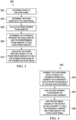
- FIG. 3 is a flowchart 300 describing a not claimed embodiment for determining the dynamic phase noise of a transmitted chirp signal.
- Phase of the chirp signal is determined at step 302.
- Phase samples of the chirp signal are determined at step 304.
- Phase samples can either be computed from the frequency samples or from the phase computed from the digitized I and Q samples. In the former case, the frequency error samples are integrated or summed up and divided by 2 ⁇ to yield phase error samples. In the latter case, a linear polynomial fit (similar to linear fit on the computed frequency samples) is applied to compute phase samples.
- ⁇ (t) at + b, where ⁇ is the phase samples of the chirp signal, 't' is the time base; 'a' is slope, and 'b' is the intercept.
- ⁇ is the phase samples of the chirp signal
- 't' is the time base
- 'a' is slope
- 'b' is the intercept.
- Predetermined phase samples are calculated in step 306.
- the predetermined phase samples are based on a mathematical model of an ideal chip signal.
- the difference between the phase samples and the predetermined phase samples is determined at step 308 to yield phase error samples.
- the power spectral density function of the phase error samples is calculated in step 310 to yield the dynamic phase noise of the transmitted chirp signal.
- the power spectral density of the phase error samples is useful to compute the noise power over a certain frequency offset.
- FIG. 4 is a flowchart 400 describing a procedure for computing the metrics of a chirp signal in situations where the chirp signal bandwidth cannot be accommodated by the analyzing equipment.
- the entire bandwidth of the chirp signal is segmented into segments, whereby each segment is analyzed.
- the chirp signal has the following characteristics:
- the chirp signal bandwidth is greater than the bandwidth of the device or equipment analyzing the chirp signal.
- the bandwidth of the chirp signal is segmented into a plurality of segments, whereby each segment has a bandwidth that is within the bandwidth of the analyzing equipment.
- the bandwidth of the chirp signal is segmented into halves of equal bandwidth which are within the bandwidth of the analyzing equipment.
- the segmented halves start and stop frequencies are entered into the analyzing equipment to extract the digitized IQ samples for each segment.
- each segment of the chirp signal is analyzed per FIGS. 2 and 3 to determine the metrics of each segment. With regard to the metrics described above, the first segment and the second segment are analyzed individually to determine their metrics.
- the root-mean-square of the metrics of each segment are added together to yield the metrics of the entire chirp signal.
- the metrics include the frequency linearity and the phase noise.
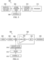
- FIG. 5 is a block diagram of test equipment 500 that measures frequency linearity and phase noise of a radar 502.
- the test equipment 500 is automated and measures the frequency linearity and phase noise of the radar 502 during production of the radar 502.
- the radar 502 has a test mode that outputs a chirp signal.
- the chirp signal has a start frequency of 2.375GHz and stop frequency of 2.41GHz.
- the test equipment 500 includes an IQ down-converter mixer 504 that is coupled to the output of the radar 502.
- the IQ down-converter mixer 504 is coupled to an external local oscillator 508 that provides a mixing signal for the IQ down-converter mixer 504.
- FIG. 5 is a block diagram of test equipment 500 that measures frequency linearity and phase noise of a radar 502.
- the radar 502 has a test mode that outputs a chirp signal.
- the chirp signal has a start frequency of 2.375GHz and stop frequency of 2.41GHz.
- the test equipment 500 includes an IQ
- the frequency of the local oscillator is 2.5GHz.
- the mixed signal output by the IQ down-converter mixer 504 is output to an intermediate frequency (IF) digitizer 510 that extracts the digital IQ signal from the mixed signal generated by the IQ down-converter mixer 504.
- IF intermediate frequency
- the combination of the IQ down-converter 504 and the IF digitizer 510 serves a similar function as a conventional signal analyzer.
- a processor 514 analyzes the digitized IQ signals generated by the IF digitizer 510 and determines the frequency linearity and dynamic phase noise of the chirp signal per the methods illustrated in FIGS. 2 and 3 .
- the IQ down-converter 504 receives its input in the form of a chirp signal generated by the radar 502.
- the chirp signal in the examples provided herein is in the frequency range of 2.375GHz to 2.51GHz.
- the chirp signal is mixed with the external LO generated by the local oscillator 508 to yield a zero IF signal.
- the zero IF signal is passed through the IF digitizer 510 to produce digitized quadrature (IQ) samples.
- the signal processing techniques described herein can be applied on the zero IF signals by the processor 514 to evaluate frequency linearity and dynamic phase noise as described above.
- FIG. 6 is a block diagram of an embodiment of more detailed test equipment 600 that measures the frequency linearity and dynamic phase noise of a chirp signal.
- the measurements are achieved on a single integrated circuit chip or by a single circuit.
- a chirp signal having a defined configuration, such as slope, bandwidth, start frequency, and stop frequency, is transmitted from a radar 602.
- the frequencies of the chirp signal are scaled down by a divider 604. Scaling down the frequencies of the chirp signal accommodates simpler design of the devices described below. In the example of FIG. 6 , the scaling is accomplished by a divider 604 that can divide the chirp signal down by a plurality of possible values, such as 2, 4, 8, 16 and 32.
- the output of the divider 604 is coupled to an input of an auxiliary mixer 606 that is used for the down-conversion process.
- the auxiliary mixer 606 is a complex mixer or a quadrature mixer.
- An external LO 610 generates a signal that has the same frequencies as the radar 602. In the embodiment of FIG. 6 , the external LO 610 generates frequencies in the range of 76GHz to 81GHz.
- the output of the external LO 610 is input to a divider 612 that may be the same or substantially similar to the mixer 604. For example, the divider 612 may reduce the frequency of the external LO 610 the same as the divider 604 reduces the signal output by the radar 602.
- the output of the divider 612 is input to an auxiliary LO 616 that is used for down-conversion.
- the output of the auxiliary LO 616 is input to the mixer 606.
- the output of the mixer 606 is coupled to a receiver 620 that includes an IF amplifier 622 and an ADC 624.
- the IF amplifier 622 is a two-staged, bi-quad IF amplifier that amplifies the output of the auxiliary mixer 606.
- the output of the amplifier 622 is digitized by the ADC 624.
- the output of the ADC 624 is processed by a processor 630 per the methods described in the flowcharts 200 and 300 of FIGS. 2 and 3 .
- the processing of the processor 630 is performed on the same circuit or integrated circuit as the other portions of the radar 602, so the processing can be absorbed as a part of software/firmware written to characterize the radar 602. For example, the processing may be performed as a self test process in the radar.
- the LO used for the radar 602 cannot be used to feed the auxiliary mixer 606 and the external LO 610 because the phase noise gets cancelled out during the down-conversion and will affect the dynamic phase noise measurement. This problem is overcome by feeding the external LO 610 from an external source. The use of other internal clocks may create noise that will adversely affect the above-described measurements.
- FIG. 7 is flowchart 700 describing a method for determining frequency linearity of a chirp signal.
- the method includes down-converting the chirp signal to quadrature signals at step 702.
- the quadrature signals are digitized to yield an IF signal.
- the instantaneous frequencies of the IF signal are determined.
- the instantaneous frequencies of the IF signal are compared to predetermined instantaneous frequencies of the chirp signal to determine frequency linearity of the chirp signal.
- FIG. 8 is a flowchart 800 describing a method for determining dynamic phase noise of a chirp signal.
- the method includes down-converting the chirp signal to quadrature signals at step 802.
- the method also includes digitizing the quadrature signals to yield an IF signal at step 804; measuring the dynamic phase of the IF signal at step 806; and comparing the measured dynamic phase of the IF signal to a predetermined dynamic phase of the chirp signal to yield dynamic phase noise of the chirp signal at step 808.
Landscapes
- Engineering & Computer Science (AREA)
- Radar, Positioning & Navigation (AREA)
- Remote Sensing (AREA)
- Computer Networks & Wireless Communication (AREA)
- Physics & Mathematics (AREA)
- General Physics & Mathematics (AREA)
- Radar Systems Or Details Thereof (AREA)
Applications Claiming Priority (2)
| Application Number | Priority Date | Filing Date | Title |
|---|---|---|---|
| US14/975,416 US10746851B2 (en) | 2015-12-18 | 2015-12-18 | Circuits and methods for determining chirp signal linearity and phase noise of a FMCW radar |
| PCT/US2016/067478 WO2017106823A1 (en) | 2015-12-18 | 2016-12-19 | Circuits and methods for determining chirp signal linearity and phase noise of a fmcw radar |
Publications (3)
| Publication Number | Publication Date |
|---|---|
| EP3391078A1 EP3391078A1 (en) | 2018-10-24 |
| EP3391078A4 EP3391078A4 (en) | 2019-08-21 |
| EP3391078B1 true EP3391078B1 (en) | 2024-11-06 |
Family
ID=59057735
Family Applications (1)
| Application Number | Title | Priority Date | Filing Date |
|---|---|---|---|
| EP16876898.4A Active EP3391078B1 (en) | 2015-12-18 | 2016-12-19 | Circuits and methods for determining chirp signal linearity and phase noise of a fmcw radar |
Country Status (5)
| Country | Link |
|---|---|
| US (1) | US10746851B2 (https=) |
| EP (1) | EP3391078B1 (https=) |
| JP (2) | JP6923944B2 (https=) |
| CN (1) | CN108351405B (https=) |
| WO (1) | WO2017106823A1 (https=) |
Families Citing this family (57)
| Publication number | Priority date | Publication date | Assignee | Title |
|---|---|---|---|---|
| US10181653B2 (en) | 2016-07-21 | 2019-01-15 | Infineon Technologies Ag | Radio frequency system for wearable device |
| US10218407B2 (en) | 2016-08-08 | 2019-02-26 | Infineon Technologies Ag | Radio frequency system and method for wearable device |
| US10466772B2 (en) | 2017-01-09 | 2019-11-05 | Infineon Technologies Ag | System and method of gesture detection for a remote device |
| US10505255B2 (en) | 2017-01-30 | 2019-12-10 | Infineon Technologies Ag | Radio frequency device packages and methods of formation thereof |
| US10602548B2 (en) | 2017-06-22 | 2020-03-24 | Infineon Technologies Ag | System and method for gesture sensing |
| US10305701B2 (en) * | 2017-07-17 | 2019-05-28 | The Boeing Company | Phase-modulated signal parameter estimation using streaming calculations |
| US10746625B2 (en) | 2017-12-22 | 2020-08-18 | Infineon Technologies Ag | System and method of monitoring a structural object using a millimeter-wave radar sensor |
| US11346936B2 (en) | 2018-01-16 | 2022-05-31 | Infineon Technologies Ag | System and method for vital signal sensing using a millimeter-wave radar sensor |
| US11278241B2 (en) | 2018-01-16 | 2022-03-22 | Infineon Technologies Ag | System and method for vital signal sensing using a millimeter-wave radar sensor |
| US10795012B2 (en) | 2018-01-22 | 2020-10-06 | Infineon Technologies Ag | System and method for human behavior modelling and power control using a millimeter-wave radar sensor |
| DE102018108219B3 (de) * | 2018-01-29 | 2019-06-19 | Infineon Technologies Ag | Spektrale Schätzung von Rauschen in Radarvorrichtungen |
| US10576328B2 (en) | 2018-02-06 | 2020-03-03 | Infineon Technologies Ag | System and method for contactless sensing on a treadmill |
| US10705198B2 (en) | 2018-03-27 | 2020-07-07 | Infineon Technologies Ag | System and method of monitoring an air flow using a millimeter-wave radar sensor |
| US10761187B2 (en) | 2018-04-11 | 2020-09-01 | Infineon Technologies Ag | Liquid detection using millimeter-wave radar sensor |
| US10775482B2 (en) | 2018-04-11 | 2020-09-15 | Infineon Technologies Ag | Human detection and identification in a setting using millimeter-wave radar |
| US10794841B2 (en) | 2018-05-07 | 2020-10-06 | Infineon Technologies Ag | Composite material structure monitoring system |
| US10399393B1 (en) | 2018-05-29 | 2019-09-03 | Infineon Technologies Ag | Radar sensor system for tire monitoring |
| US10903567B2 (en) | 2018-06-04 | 2021-01-26 | Infineon Technologies Ag | Calibrating a phased array system |
| US11416077B2 (en) | 2018-07-19 | 2022-08-16 | Infineon Technologies Ag | Gesture detection system and method using a radar sensor |
| US10928501B2 (en) | 2018-08-28 | 2021-02-23 | Infineon Technologies Ag | Target detection in rainfall and snowfall conditions using mmWave radar |
| US11183772B2 (en) | 2018-09-13 | 2021-11-23 | Infineon Technologies Ag | Embedded downlight and radar system |
| US11125869B2 (en) | 2018-10-16 | 2021-09-21 | Infineon Technologies Ag | Estimating angle of human target using mmWave radar |
| US11397239B2 (en) | 2018-10-24 | 2022-07-26 | Infineon Technologies Ag | Radar sensor FSM low power mode |
| US11360185B2 (en) | 2018-10-24 | 2022-06-14 | Infineon Technologies Ag | Phase coded FMCW radar |
| CN109490857B (zh) * | 2018-10-29 | 2023-01-06 | 北京遥感设备研究所 | 一种雷达设备lfm脉冲信号调频非线性度确定方法及系统 |
| EP3654053A1 (en) | 2018-11-14 | 2020-05-20 | Infineon Technologies AG | Package with acoustic sensing device(s) and millimeter wave sensing elements |
| US11087115B2 (en) | 2019-01-22 | 2021-08-10 | Infineon Technologies Ag | User authentication using mm-Wave sensor for automotive radar systems |
| US11355838B2 (en) | 2019-03-18 | 2022-06-07 | Infineon Technologies Ag | Integration of EBG structures (single layer/multi-layer) for isolation enhancement in multilayer embedded packaging technology at mmWave |
| CN113557443B (zh) * | 2019-03-18 | 2025-03-04 | 瑞典爱立信有限公司 | 用于lte许可辅助接入动态频率选择的长脉冲雷达啁啾检测器的系统和方法 |
| US11126885B2 (en) | 2019-03-21 | 2021-09-21 | Infineon Technologies Ag | Character recognition in air-writing based on network of radars |
| US11454696B2 (en) | 2019-04-05 | 2022-09-27 | Infineon Technologies Ag | FMCW radar integration with communication system |
| US11327167B2 (en) | 2019-09-13 | 2022-05-10 | Infineon Technologies Ag | Human target tracking system and method |
| US11774592B2 (en) | 2019-09-18 | 2023-10-03 | Infineon Technologies Ag | Multimode communication and radar system resource allocation |
| US11709244B2 (en) * | 2019-10-21 | 2023-07-25 | Banner Engineering Corp. | Near range radar |
| US11435443B2 (en) | 2019-10-22 | 2022-09-06 | Infineon Technologies Ag | Integration of tracking with classifier in mmwave radar |
| US11808883B2 (en) | 2020-01-31 | 2023-11-07 | Infineon Technologies Ag | Synchronization of multiple mmWave devices |
| US11614516B2 (en) | 2020-02-19 | 2023-03-28 | Infineon Technologies Ag | Radar vital signal tracking using a Kalman filter |
| CN113541727B (zh) * | 2020-03-31 | 2023-04-28 | 华为云计算技术有限公司 | 毫米波雷达通信方法、装置及可读存储介质 |
| US11650318B2 (en) | 2020-04-06 | 2023-05-16 | Gm Cruise Holdings Llc | Characterizing linearity of an optical frequency chirp output by an FMCW laser |
| US11585891B2 (en) | 2020-04-20 | 2023-02-21 | Infineon Technologies Ag | Radar-based vital sign estimation |
| US11567185B2 (en) | 2020-05-05 | 2023-01-31 | Infineon Technologies Ag | Radar-based target tracking using motion detection |
| US11774553B2 (en) | 2020-06-18 | 2023-10-03 | Infineon Technologies Ag | Parametric CNN for radar processing |
| US11704917B2 (en) | 2020-07-09 | 2023-07-18 | Infineon Technologies Ag | Multi-sensor analysis of food |
| CN112098955B (zh) * | 2020-08-14 | 2024-04-12 | 西安电子科技大学 | 基于线性调频信号逼近期望功率谱的发射波形优化方法 |
| US11614511B2 (en) | 2020-09-17 | 2023-03-28 | Infineon Technologies Ag | Radar interference mitigation |
| US11709247B2 (en) * | 2020-09-22 | 2023-07-25 | Ay Dee Kay Llc | Fast chirp synthesis via segmented frequency shifting |
| US11719787B2 (en) | 2020-10-30 | 2023-08-08 | Infineon Technologies Ag | Radar-based target set generation |
| US11719805B2 (en) | 2020-11-18 | 2023-08-08 | Infineon Technologies Ag | Radar based tracker using empirical mode decomposition (EMD) and invariant feature transform (IFT) |
| US12189021B2 (en) | 2021-02-18 | 2025-01-07 | Infineon Technologies Ag | Radar-based target tracker |
| US11662430B2 (en) | 2021-03-17 | 2023-05-30 | Infineon Technologies Ag | MmWave radar testing |
| US11950895B2 (en) | 2021-05-28 | 2024-04-09 | Infineon Technologies Ag | Radar sensor system for blood pressure sensing, and associated method |
| US12307761B2 (en) | 2021-08-06 | 2025-05-20 | Infineon Technologies Ag | Scene-adaptive radar |
| US12405351B2 (en) | 2022-03-25 | 2025-09-02 | Infineon Technologies Ag | Adaptive Tx-Rx crosstalk cancellation for radar systems |
| US12399254B2 (en) | 2022-06-07 | 2025-08-26 | Infineon Technologies Ag | Radar-based single target vital sensing |
| US12399271B2 (en) | 2022-07-20 | 2025-08-26 | Infineon Technologies Ag | Radar-based target tracker |
| US12254670B2 (en) | 2022-07-29 | 2025-03-18 | Infineon Technologies Ag | Radar-based activity classification |
| US12504526B2 (en) | 2022-09-21 | 2025-12-23 | Infineon Technologies Ag | Radar-based segmented presence detection |
Family Cites Families (34)
| Publication number | Priority date | Publication date | Assignee | Title |
|---|---|---|---|---|
| DE4104792A1 (de) | 1991-02-16 | 1992-08-20 | Bosch Gmbh Robert | Fmcw-radarsystem mit linearer frequenzmodulation |
| US5376938A (en) | 1994-04-04 | 1994-12-27 | The United States Of America As Represented By The Secretary Of The Navy | Method and apparatus for maintaining linearity and frequency accuracy of an FM chirp waveform |
| US5964132A (en) | 1996-06-24 | 1999-10-12 | Icc Innovative Concepts Corp. | Multi-function utility tool |
| US6091356A (en) * | 1998-10-05 | 2000-07-18 | Sensor Concepts Incorporated | Chirp source with rolling frequency lock for generating linear frequency chirps |
| JP2003507716A (ja) * | 1999-08-12 | 2003-02-25 | オートモーティブ システムズ ラボラトリー インコーポレーテッド | ニューラルネットワークレーダプロセッサ |
| US6922555B1 (en) * | 1999-09-02 | 2005-07-26 | Koninklijke Philips Electronics N.V. | Phase interpolation receiver for angle modulated RF signals |
| US7061998B1 (en) * | 2002-02-05 | 2006-06-13 | Itt Manufacturing Enterprises, Inc. | Methods and apparatus for downconverting signals from intermediate frequency to baseband |
| JP3903814B2 (ja) * | 2002-03-08 | 2007-04-11 | 三菱電機株式会社 | 電波監視装置 |
| US6624780B1 (en) * | 2002-10-02 | 2003-09-23 | The United States Of America As Represented By The Secretary Of The Navy | False target radar image generator for countering wideband imaging radars |
| US20040150548A1 (en) * | 2003-02-03 | 2004-08-05 | Walmsley Prescott A. | Linear frequency modulation superimposed on double sideband diplex radar |
| JP3944130B2 (ja) * | 2003-07-08 | 2007-07-11 | 三菱電機株式会社 | 移動体のレ−ダ方式、レ−ダ装置、レーダ信号処理方法、及びレーダ信号処理装置 |
| JP4241451B2 (ja) * | 2004-03-17 | 2009-03-18 | 三菱電機株式会社 | レーダ試験方法 |
| US7317309B2 (en) * | 2004-06-07 | 2008-01-08 | Advantest Corporation | Wideband signal analyzing apparatus, wideband period jitter analyzing apparatus, and wideband skew analyzing apparatus |
| US7154346B2 (en) * | 2004-07-30 | 2006-12-26 | Broadcom Corporation | Apparatus and method to provide a local oscillator signal |
| US7535976B2 (en) * | 2004-07-30 | 2009-05-19 | Broadcom Corporation | Apparatus and method for integration of tuner functions in a digital receiver |
| GB0421520D0 (en) | 2004-09-28 | 2004-10-27 | Qinetiq Ltd | Frequency modulated continuous wave (FMCW) radar having improved frquency sweep linearity |
| US7345744B2 (en) * | 2005-06-06 | 2008-03-18 | Raytheon Company | Optical delay line to correct phase errors in coherent ladar |
| DE102006031351A1 (de) | 2006-07-06 | 2008-01-17 | Infineon Technologies Ag | Vorrichtung und Verfahren zum Messen einer Phasenabweichung |
| WO2008072481A1 (ja) * | 2006-12-11 | 2008-06-19 | Murata Manufacturing Co., Ltd. | レーダ装置 |
| EP2184857A4 (en) * | 2007-08-28 | 2013-10-16 | Fujitsu Ltd | PHASE LOCKED OSCILLATOR AND RADAR EQUIPMENT THEREWITH |
| JP2010237172A (ja) * | 2009-03-31 | 2010-10-21 | Toshiba Corp | Fmcw信号生成回路 |
| CN102770781B (zh) * | 2010-03-09 | 2014-08-27 | 古河电气工业株式会社 | 脉冲雷达装置及其控制方法 |
| JP5178761B2 (ja) * | 2010-03-19 | 2013-04-10 | 株式会社東芝 | Fmcw信号生成回路及びレーダー装置 |
| EP2630693A4 (en) * | 2010-10-20 | 2015-07-29 | Aviat Networks Inc | SYSTEMS AND METHODS FOR ENHANCING ENERGY EFFICIENCY AND LINEARIZATION OF RADIO FREQUENCY TRANSMITTERS |
| US8686736B2 (en) * | 2010-11-23 | 2014-04-01 | Infineon Technologies Ag | System and method for testing a radio frequency integrated circuit |
| CN201965232U (zh) * | 2010-12-20 | 2011-09-07 | 河北珠峰仪器仪表设备有限公司 | 一种高扫频线性度的调频连续波雷达测距电路 |
| JP5566974B2 (ja) * | 2011-08-29 | 2014-08-06 | 株式会社東芝 | 信号生成回路、発振装置、レーダー装置 |
| JP2013221756A (ja) * | 2012-04-12 | 2013-10-28 | Furuno Electric Co Ltd | レーダ装置、及びレーダ送受信方法 |
| US8687736B1 (en) * | 2012-12-09 | 2014-04-01 | Phuong Huynh | Multi-band bandpass-sampling receiver |
| DE102013207464B4 (de) | 2013-04-24 | 2023-07-13 | Rohde & Schwarz Gmbh & Co. Kg | Messverfahren und Messgerät zur Vermessung von breitbandigen Messsignalen |
| EP3044870B1 (en) * | 2013-09-12 | 2019-05-15 | Vayyar Imaging Ltd. | Apparatus and methods for signal generation, reception, and self-calibration |
| JP6407555B2 (ja) * | 2014-04-24 | 2018-10-17 | 浜松ホトニクス株式会社 | 画像生成装置及び画像生成方法 |
| DE102015112392B3 (de) * | 2015-07-29 | 2016-11-17 | Infineon Technologies Ag | Verfahren und Vorrichtung zum Kalibrieren eines IQ-Modulators |
| CN109239708A (zh) * | 2018-09-19 | 2019-01-18 | 天津大学 | 一种实现生命体征探测和短距离定位的双频电路结构 |
-
2015
- 2015-12-18 US US14/975,416 patent/US10746851B2/en active Active
-
2016
- 2016-12-19 JP JP2018532051A patent/JP6923944B2/ja active Active
- 2016-12-19 EP EP16876898.4A patent/EP3391078B1/en active Active
- 2016-12-19 WO PCT/US2016/067478 patent/WO2017106823A1/en not_active Ceased
- 2016-12-19 CN CN201680064535.2A patent/CN108351405B/zh active Active
-
2021
- 2021-07-21 JP JP2021120275A patent/JP7235386B2/ja active Active
Also Published As
| Publication number | Publication date |
|---|---|
| JP7235386B2 (ja) | 2023-03-08 |
| JP2018538539A (ja) | 2018-12-27 |
| US10746851B2 (en) | 2020-08-18 |
| EP3391078A1 (en) | 2018-10-24 |
| CN108351405A (zh) | 2018-07-31 |
| CN108351405B (zh) | 2023-08-08 |
| WO2017106823A1 (en) | 2017-06-22 |
| JP2021175980A (ja) | 2021-11-04 |
| JP6923944B2 (ja) | 2021-08-25 |
| EP3391078A4 (en) | 2019-08-21 |
| US20170176574A1 (en) | 2017-06-22 |
Similar Documents
| Publication | Publication Date | Title |
|---|---|---|
| EP3391078B1 (en) | Circuits and methods for determining chirp signal linearity and phase noise of a fmcw radar | |
| US10771170B2 (en) | Real-time network analyzer and applications | |
| US9252895B1 (en) | System and method of measuring full spectrum of modulated output signal from device under test | |
| US8805313B2 (en) | Magnitude and phase response calibration of receivers | |
| US9998240B2 (en) | Electric field intensity distribution measurement device and electric field intensity distribution measurement method | |
| JP5073887B2 (ja) | 自動周波数ステッピングノイズ測定テストシステム | |
| US10735113B2 (en) | Near-field measurement system and near-field measurement method | |
| US20170033808A1 (en) | Real-time network analyzer and applications | |
| US11346869B2 (en) | Calibration setup and method of measuring a signal generator | |
| US9698919B1 (en) | Method and apparatus for spectral stitching discontinuous spectra using reference channel, pilot tones and comb signal | |
| US9673914B2 (en) | Method and apparatus for spectral stitching using reference channel and a pilot tone | |
| JP2005292147A (ja) | スペクトルおよび/またはネットワーク解析用測定装置のダイナミックレンジおよび測定確度を高めるための方法および装置 | |
| WO2002010776A1 (en) | Signal measurement | |
| JP2006017486A (ja) | 核磁気共鳴を用いるスペクトル分析方法および核磁気共鳴装置 | |
| CN109541332B (zh) | 基于宽带锁频和数字鉴频的相位噪声测量装置 | |
| KR102154228B1 (ko) | 전파 토모그래피 시스템에서 위상 측정 장치 및 방법 | |
| US20250192812A1 (en) | Phase characteristic measurement device, signal generator and signal analyzer having same, and phase characteristic measurement method | |
| US11415446B2 (en) | Flow measuring system | |
| Anthonys et al. | Jitter measurement in digital signals by using software defined radio technology | |
| US12470308B2 (en) | Measurement system and method for measuring and analyzing modulated signals | |
| US12352792B2 (en) | Detector circuit, signal processing circuit, and measurement instrument | |
| JP2019158418A (ja) | 測定システム及び測定方法 | |
| KR20030044105A (ko) | 위상 잡음 측정장치 | |
| CN119716756A (zh) | 用于确定与rf发射信道相关的相位信息的方法和雷达mmic设备 | |
| CN114217148A (zh) | 基于prf谱线的脉冲调制波相位噪声定标装置及方法 |
Legal Events
| Date | Code | Title | Description |
|---|---|---|---|
| STAA | Information on the status of an ep patent application or granted ep patent |
Free format text: STATUS: THE INTERNATIONAL PUBLICATION HAS BEEN MADE |
|
| PUAI | Public reference made under article 153(3) epc to a published international application that has entered the european phase |
Free format text: ORIGINAL CODE: 0009012 |
|
| STAA | Information on the status of an ep patent application or granted ep patent |
Free format text: STATUS: REQUEST FOR EXAMINATION WAS MADE |
|
| 17P | Request for examination filed |
Effective date: 20180718 |
|
| AK | Designated contracting states |
Kind code of ref document: A1 Designated state(s): AL AT BE BG CH CY CZ DE DK EE ES FI FR GB GR HR HU IE IS IT LI LT LU LV MC MK MT NL NO PL PT RO RS SE SI SK SM TR |
|
| AX | Request for extension of the european patent |
Extension state: BA ME |
|
| DAV | Request for validation of the european patent (deleted) | ||
| DAX | Request for extension of the european patent (deleted) | ||
| A4 | Supplementary search report drawn up and despatched |
Effective date: 20190718 |
|
| RIC1 | Information provided on ipc code assigned before grant |
Ipc: G01S 13/34 20060101ALI20190712BHEP Ipc: G01S 7/40 20060101AFI20190712BHEP Ipc: G01S 7/35 20060101ALN20190712BHEP |
|
| STAA | Information on the status of an ep patent application or granted ep patent |
Free format text: STATUS: EXAMINATION IS IN PROGRESS |
|
| 17Q | First examination report despatched |
Effective date: 20210831 |
|
| REG | Reference to a national code |
Ref legal event code: R079 Ipc: G01S0007400000 Ref country code: DE Ref legal event code: R079 Ref document number: 602016090167 Country of ref document: DE Free format text: PREVIOUS MAIN CLASS: G01S0013000000 Ipc: G01S0007400000 |
|
| GRAP | Despatch of communication of intention to grant a patent |
Free format text: ORIGINAL CODE: EPIDOSNIGR1 |
|
| STAA | Information on the status of an ep patent application or granted ep patent |
Free format text: STATUS: GRANT OF PATENT IS INTENDED |
|
| RIC1 | Information provided on ipc code assigned before grant |
Ipc: G01S 7/35 20060101ALN20240523BHEP Ipc: G01S 13/34 20060101ALI20240523BHEP Ipc: G01S 7/40 20060101AFI20240523BHEP |
|
| RIC1 | Information provided on ipc code assigned before grant |
Ipc: G01S 7/35 20060101ALN20240527BHEP Ipc: G01S 13/34 20060101ALI20240527BHEP Ipc: G01S 7/40 20060101AFI20240527BHEP |
|
| INTG | Intention to grant announced |
Effective date: 20240625 |
|
| P01 | Opt-out of the competence of the unified patent court (upc) registered |
Free format text: CASE NUMBER: APP_40123/2024 Effective date: 20240705 |
|
| GRAS | Grant fee paid |
Free format text: ORIGINAL CODE: EPIDOSNIGR3 |
|
| GRAA | (expected) grant |
Free format text: ORIGINAL CODE: 0009210 |
|
| STAA | Information on the status of an ep patent application or granted ep patent |
Free format text: STATUS: THE PATENT HAS BEEN GRANTED |
|
| AK | Designated contracting states |
Kind code of ref document: B1 Designated state(s): AL AT BE BG CH CY CZ DE DK EE ES FI FR GB GR HR HU IE IS IT LI LT LU LV MC MK MT NL NO PL PT RO RS SE SI SK SM TR |
|
| REG | Reference to a national code |
Ref country code: GB Ref legal event code: FG4D |
|
| REG | Reference to a national code |
Ref country code: CH Ref legal event code: EP |
|
| REG | Reference to a national code |
Ref country code: DE Ref legal event code: R096 Ref document number: 602016090167 Country of ref document: DE |
|
| REG | Reference to a national code |
Ref country code: IE Ref legal event code: FG4D |
|
| REG | Reference to a national code |
Ref country code: LT Ref legal event code: MG9D |
|
| REG | Reference to a national code |
Ref country code: NL Ref legal event code: MP Effective date: 20241106 |
|
| PG25 | Lapsed in a contracting state [announced via postgrant information from national office to epo] |
Ref country code: HR Free format text: LAPSE BECAUSE OF FAILURE TO SUBMIT A TRANSLATION OF THE DESCRIPTION OR TO PAY THE FEE WITHIN THE PRESCRIBED TIME-LIMIT Effective date: 20241106 Ref country code: PT Free format text: LAPSE BECAUSE OF FAILURE TO SUBMIT A TRANSLATION OF THE DESCRIPTION OR TO PAY THE FEE WITHIN THE PRESCRIBED TIME-LIMIT Effective date: 20250306 Ref country code: IS Free format text: LAPSE BECAUSE OF FAILURE TO SUBMIT A TRANSLATION OF THE DESCRIPTION OR TO PAY THE FEE WITHIN THE PRESCRIBED TIME-LIMIT Effective date: 20250306 |
|
| PG25 | Lapsed in a contracting state [announced via postgrant information from national office to epo] |
Ref country code: FI Free format text: LAPSE BECAUSE OF FAILURE TO SUBMIT A TRANSLATION OF THE DESCRIPTION OR TO PAY THE FEE WITHIN THE PRESCRIBED TIME-LIMIT Effective date: 20241106 Ref country code: NL Free format text: LAPSE BECAUSE OF FAILURE TO SUBMIT A TRANSLATION OF THE DESCRIPTION OR TO PAY THE FEE WITHIN THE PRESCRIBED TIME-LIMIT Effective date: 20241106 |
|
| REG | Reference to a national code |
Ref country code: AT Ref legal event code: MK05 Ref document number: 1739929 Country of ref document: AT Kind code of ref document: T Effective date: 20241106 |
|
| PG25 | Lapsed in a contracting state [announced via postgrant information from national office to epo] |
Ref country code: BG Free format text: LAPSE BECAUSE OF FAILURE TO SUBMIT A TRANSLATION OF THE DESCRIPTION OR TO PAY THE FEE WITHIN THE PRESCRIBED TIME-LIMIT Effective date: 20241106 |
|
| PG25 | Lapsed in a contracting state [announced via postgrant information from national office to epo] |
Ref country code: ES Free format text: LAPSE BECAUSE OF FAILURE TO SUBMIT A TRANSLATION OF THE DESCRIPTION OR TO PAY THE FEE WITHIN THE PRESCRIBED TIME-LIMIT Effective date: 20241106 |
|
| PG25 | Lapsed in a contracting state [announced via postgrant information from national office to epo] |
Ref country code: NO Free format text: LAPSE BECAUSE OF FAILURE TO SUBMIT A TRANSLATION OF THE DESCRIPTION OR TO PAY THE FEE WITHIN THE PRESCRIBED TIME-LIMIT Effective date: 20250206 |
|
| PG25 | Lapsed in a contracting state [announced via postgrant information from national office to epo] |
Ref country code: LV Free format text: LAPSE BECAUSE OF FAILURE TO SUBMIT A TRANSLATION OF THE DESCRIPTION OR TO PAY THE FEE WITHIN THE PRESCRIBED TIME-LIMIT Effective date: 20241106 Ref country code: GR Free format text: LAPSE BECAUSE OF FAILURE TO SUBMIT A TRANSLATION OF THE DESCRIPTION OR TO PAY THE FEE WITHIN THE PRESCRIBED TIME-LIMIT Effective date: 20250207 Ref country code: AT Free format text: LAPSE BECAUSE OF FAILURE TO SUBMIT A TRANSLATION OF THE DESCRIPTION OR TO PAY THE FEE WITHIN THE PRESCRIBED TIME-LIMIT Effective date: 20241106 |
|
| PG25 | Lapsed in a contracting state [announced via postgrant information from national office to epo] |
Ref country code: PL Free format text: LAPSE BECAUSE OF FAILURE TO SUBMIT A TRANSLATION OF THE DESCRIPTION OR TO PAY THE FEE WITHIN THE PRESCRIBED TIME-LIMIT Effective date: 20241106 |
|
| PG25 | Lapsed in a contracting state [announced via postgrant information from national office to epo] |
Ref country code: RS Free format text: LAPSE BECAUSE OF FAILURE TO SUBMIT A TRANSLATION OF THE DESCRIPTION OR TO PAY THE FEE WITHIN THE PRESCRIBED TIME-LIMIT Effective date: 20250206 |
|
| PG25 | Lapsed in a contracting state [announced via postgrant information from national office to epo] |
Ref country code: SM Free format text: LAPSE BECAUSE OF FAILURE TO SUBMIT A TRANSLATION OF THE DESCRIPTION OR TO PAY THE FEE WITHIN THE PRESCRIBED TIME-LIMIT Effective date: 20241106 |
|
| PG25 | Lapsed in a contracting state [announced via postgrant information from national office to epo] |
Ref country code: DK Free format text: LAPSE BECAUSE OF FAILURE TO SUBMIT A TRANSLATION OF THE DESCRIPTION OR TO PAY THE FEE WITHIN THE PRESCRIBED TIME-LIMIT Effective date: 20241106 |
|
| PG25 | Lapsed in a contracting state [announced via postgrant information from national office to epo] |
Ref country code: EE Free format text: LAPSE BECAUSE OF FAILURE TO SUBMIT A TRANSLATION OF THE DESCRIPTION OR TO PAY THE FEE WITHIN THE PRESCRIBED TIME-LIMIT Effective date: 20241106 |
|
| PG25 | Lapsed in a contracting state [announced via postgrant information from national office to epo] |
Ref country code: RO Free format text: LAPSE BECAUSE OF FAILURE TO SUBMIT A TRANSLATION OF THE DESCRIPTION OR TO PAY THE FEE WITHIN THE PRESCRIBED TIME-LIMIT Effective date: 20241106 |
|
| PG25 | Lapsed in a contracting state [announced via postgrant information from national office to epo] |
Ref country code: SK Free format text: LAPSE BECAUSE OF FAILURE TO SUBMIT A TRANSLATION OF THE DESCRIPTION OR TO PAY THE FEE WITHIN THE PRESCRIBED TIME-LIMIT Effective date: 20241106 |
|
| PG25 | Lapsed in a contracting state [announced via postgrant information from national office to epo] |
Ref country code: CZ Free format text: LAPSE BECAUSE OF FAILURE TO SUBMIT A TRANSLATION OF THE DESCRIPTION OR TO PAY THE FEE WITHIN THE PRESCRIBED TIME-LIMIT Effective date: 20241106 |
|
| PG25 | Lapsed in a contracting state [announced via postgrant information from national office to epo] |
Ref country code: IT Free format text: LAPSE BECAUSE OF FAILURE TO SUBMIT A TRANSLATION OF THE DESCRIPTION OR TO PAY THE FEE WITHIN THE PRESCRIBED TIME-LIMIT Effective date: 20241106 |
|
| REG | Reference to a national code |
Ref country code: CH Ref legal event code: PL |
|
| REG | Reference to a national code |
Ref country code: DE Ref legal event code: R097 Ref document number: 602016090167 Country of ref document: DE |
|
| PG25 | Lapsed in a contracting state [announced via postgrant information from national office to epo] |
Ref country code: LU Free format text: LAPSE BECAUSE OF NON-PAYMENT OF DUE FEES Effective date: 20241219 |
|
| PG25 | Lapsed in a contracting state [announced via postgrant information from national office to epo] |
Ref country code: SE Free format text: LAPSE BECAUSE OF FAILURE TO SUBMIT A TRANSLATION OF THE DESCRIPTION OR TO PAY THE FEE WITHIN THE PRESCRIBED TIME-LIMIT Effective date: 20241106 |
|
| PLBE | No opposition filed within time limit |
Free format text: ORIGINAL CODE: 0009261 |
|
| STAA | Information on the status of an ep patent application or granted ep patent |
Free format text: STATUS: NO OPPOSITION FILED WITHIN TIME LIMIT |
|
| PG25 | Lapsed in a contracting state [announced via postgrant information from national office to epo] |
Ref country code: MC Free format text: LAPSE BECAUSE OF FAILURE TO SUBMIT A TRANSLATION OF THE DESCRIPTION OR TO PAY THE FEE WITHIN THE PRESCRIBED TIME-LIMIT Effective date: 20241106 |
|
| REG | Reference to a national code |
Ref country code: BE Ref legal event code: MM Effective date: 20241231 |
|
| 26N | No opposition filed |
Effective date: 20250807 |
|
| PG25 | Lapsed in a contracting state [announced via postgrant information from national office to epo] |
Ref country code: BE Free format text: LAPSE BECAUSE OF NON-PAYMENT OF DUE FEES Effective date: 20241231 |
|
| PG25 | Lapsed in a contracting state [announced via postgrant information from national office to epo] |
Ref country code: CH Free format text: LAPSE BECAUSE OF NON-PAYMENT OF DUE FEES Effective date: 20241231 |
|
| PG25 | Lapsed in a contracting state [announced via postgrant information from national office to epo] |
Ref country code: IE Free format text: LAPSE BECAUSE OF NON-PAYMENT OF DUE FEES Effective date: 20241219 |
|
| PGFP | Annual fee paid to national office [announced via postgrant information from national office to epo] |
Ref country code: DE Payment date: 20251126 Year of fee payment: 10 |
|
| PGFP | Annual fee paid to national office [announced via postgrant information from national office to epo] |
Ref country code: GB Payment date: 20251120 Year of fee payment: 10 |
|
| PGFP | Annual fee paid to national office [announced via postgrant information from national office to epo] |
Ref country code: FR Payment date: 20251120 Year of fee payment: 10 |