EP3390904B1 - Glasfaserlichtquelle mit zusammengesetzter deckschichtstruktur - Google Patents
Glasfaserlichtquelle mit zusammengesetzter deckschichtstruktur Download PDFInfo
- Publication number
- EP3390904B1 EP3390904B1 EP16828776.1A EP16828776A EP3390904B1 EP 3390904 B1 EP3390904 B1 EP 3390904B1 EP 16828776 A EP16828776 A EP 16828776A EP 3390904 B1 EP3390904 B1 EP 3390904B1
- Authority
- EP
- European Patent Office
- Prior art keywords
- light
- optical fiber
- solid body
- composite
- composite structure
- Prior art date
- Legal status (The legal status is an assumption and is not a legal conclusion. Google has not performed a legal analysis and makes no representation as to the accuracy of the status listed.)
- Active
Links
Images



Classifications
-
- F—MECHANICAL ENGINEERING; LIGHTING; HEATING; WEAPONS; BLASTING
- F21—LIGHTING
- F21V—FUNCTIONAL FEATURES OR DETAILS OF LIGHTING DEVICES OR SYSTEMS THEREOF; STRUCTURAL COMBINATIONS OF LIGHTING DEVICES WITH OTHER ARTICLES, NOT OTHERWISE PROVIDED FOR
- F21V5/00—Refractors for light sources
- F21V5/002—Refractors for light sources using microoptical elements for redirecting or diffusing light
- F21V5/004—Refractors for light sources using microoptical elements for redirecting or diffusing light using microlenses
-
- F—MECHANICAL ENGINEERING; LIGHTING; HEATING; WEAPONS; BLASTING
- F21—LIGHTING
- F21V—FUNCTIONAL FEATURES OR DETAILS OF LIGHTING DEVICES OR SYSTEMS THEREOF; STRUCTURAL COMBINATIONS OF LIGHTING DEVICES WITH OTHER ARTICLES, NOT OTHERWISE PROVIDED FOR
- F21V5/00—Refractors for light sources
- F21V5/02—Refractors for light sources of prismatic shape
-
- F—MECHANICAL ENGINEERING; LIGHTING; HEATING; WEAPONS; BLASTING
- F21—LIGHTING
- F21V—FUNCTIONAL FEATURES OR DETAILS OF LIGHTING DEVICES OR SYSTEMS THEREOF; STRUCTURAL COMBINATIONS OF LIGHTING DEVICES WITH OTHER ARTICLES, NOT OTHERWISE PROVIDED FOR
- F21V7/00—Reflectors for light sources
- F21V7/04—Optical design
- F21V7/06—Optical design with parabolic curvature
-
- G—PHYSICS
- G02—OPTICS
- G02B—OPTICAL ELEMENTS, SYSTEMS OR APPARATUS
- G02B6/00—Light guides; Structural details of arrangements comprising light guides and other optical elements, e.g. couplings
- G02B6/0001—Light guides; Structural details of arrangements comprising light guides and other optical elements, e.g. couplings specially adapted for lighting devices or systems
- G02B6/0003—Light guides; Structural details of arrangements comprising light guides and other optical elements, e.g. couplings specially adapted for lighting devices or systems the light guides being doped with fluorescent agents
-
- G—PHYSICS
- G02—OPTICS
- G02B—OPTICAL ELEMENTS, SYSTEMS OR APPARATUS
- G02B6/00—Light guides; Structural details of arrangements comprising light guides and other optical elements, e.g. couplings
- G02B6/0001—Light guides; Structural details of arrangements comprising light guides and other optical elements, e.g. couplings specially adapted for lighting devices or systems
- G02B6/0005—Light guides; Structural details of arrangements comprising light guides and other optical elements, e.g. couplings specially adapted for lighting devices or systems the light guides being of the fibre type
- G02B6/001—Light guides; Structural details of arrangements comprising light guides and other optical elements, e.g. couplings specially adapted for lighting devices or systems the light guides being of the fibre type the light being emitted along at least a portion of the lateral surface of the fibre
Definitions
- An embodiment of the invention relates to a light source that has an optical fiber based side-emitter embedded in a composite overcoating structure, where the latter is designed to modify the illumination scheme of the optical fiber side-emitted light, and ease integration of the light source into a system. Other embodiments are also described.
- luminescent materials are integrated inside the fiber-core material, inside the cladding, or inside a coating of the fiber, to partially or completely convert the primary or propagating light into secondary light that has lower or higher wavelength than the primary light.
- WO2012146960 discloses a waveguide to receive a primary light in a longitudinal direction.
- the waveguide has formed therein scattering structures that redirect the propagating primary light out of the waveguide, for instance in a transverse direction.
- a photo-luminescent layer absorbs the re-directed primary light to thereby emit secondary wavelength converted light having a different wavelength than the primary light.
- An embodiment of the invention as defined by claim 1 is an optical fiber side-emitting light source that has a side-emitting optical fiber as the light emitter, having a fiber core through which primary light propagates, e.g., in accordance with total internal reflection off a fiber cladding of the optical fiber.
- a lengthwise segment, of a whole length of the fiber contains a scattering region, which serves to redirect the propagating primary light (that is, propagating in the fiber until it enters the segment) sideways out of the fiber.
- An active, photoluminescent material may also been integrated with the fiber, e.g., as a layer or coating on an outer side surface of the cladding of the fiber, to be stimulated by the redirected primary light and produce wavelength converted secondary light.
- the composite overcoating structure is made of dissimilar materials that are chosen such that it is selectively opaque, transparent or semi-transparent in an asymmetric way to the side-emitted light emerging from the fiber; be made of dissimilar materials that are chosen such that it is less flexible than the fiber thereby forming an exoskeleton; be made of dissimilar materials that are chosen such that it is impermeable or hermetic to the external environment (e.g.
- a method for manufacturing the inactive, light transmissive portion of the shaped overcoating structure includes a succession of an extrusion process where the fiber has been previously formed and is fed through a nozzle while being covered by the inactive light transmissive material in fluid form, that gives a preliminary shape to the light transmissive portion (once the light transmissive material has solidified after extrusion), followed with a selective photo- or thermal polymerization process or a mechanical abrasion process to achieve precision in the shaping of the bottom surface of the extruded light transmissive portion.
- Another method for manufacturing the shaped, overcoating structure may be the succession of an overmolding process, where the fiber is positioned inside a mold that exhibits the counter or complementary shape of the final or desired light transmissive portion, combined with a selective photo- or thermal polymerization process to achieve precision in the shaping of the bottom surface of the light transmissive portion.
- the formation of the light transmissive part may be followed with a method for manufacturing the reflective part, on the bottom surface of the light transmissive part, by depositing, sputtering, dipping or evaporating a reflective material such as aluminum onto the bottom surface of the light transmissive part.
- a diffusive layer may be formed on the bottom surface; this may be done by depositing, sputtering or evaporating a mixture of diffusing particles onto the bottom surface, or dipping the light transmissive portion into a mixture of diffusing particles.
- an optical fiber side-emitting light source whose overcoating structure is made of dissimilar materials that are designed and shaped in order to support the redirection and re-shaping of the light emerging from the side of an optical fiber that is embedded in the overcoating structure.
- the light source may be used as part of any illumination system.
- a fiber-based side-emitting light source has an optical fiber 6 that may have a core and a cladding.
- Primary propagating light is produced by a light emitter such as a laser or a light emitting diode (LED) that is coupled to the fiber (not shown.)
- the primary light propagates along a center longitudinal axis 2 of the fiber 6, in a downstream direction as shown, until it is scattered out of the fiber through a side of the fiber 6, by a scattering zone (e.g., formed in a core of the fiber 6.)
- the scattered radiation or out-coupled light takes place in a direction substantially transverse to the longitudinal axis 2 of the fiber 6, either in a directional manner (forming a cone or lobe of light having a radial span of under 360°) or in an isotropic or omnidirectional manner (radiating at equal strength all around the fiber).
- the fiber 6 may also have formed on it a layer of photoluminescent material to perform wavelength conversion upon the primary propagating light, to result in a side-emitted light that includes secondary light having a different wavelength than the primary light.
- the resulting side-emitted light may exhibit a broader spectrum as compared to the primary light, e.g. white light resulting from the combination of unabsorbed primary light and the secondary light.
- the photoluminescent material and the wavelength of the primary light may be selected such that very little primary light is left unabsorbed, resulting in the side-emitted light emerging from the fiber 6 being dominated by the secondary light, e.g. red or infrared.
- a light transmissive part 3 that conforms to the side surface of the fiber 6, and a reflective part 4 (also referred to as a reflective backing), both forming a single, composite overcoating structure (where the fiber 6 is "embedded” within the light transmissive part 3 of the composite overcoating structure.
- the light transmissive part 3 may be made of a single, light transmissive, inactive (i.e., not photoluminescent, or not wavelength converting) material, e.g., polycarbonate, and may completely surround the side surface of the fiber 6 and may leave no air gaps between the fiber and the reflective part 4, the latter conforming to the bottom surface of the light transmissive part 3 (as shown.) All of the light transmissive part 3 may be made of the same material, or it may be composed of layers of different materials.
- the overcoating structure of Fig. 1a may alternatively be viewed as having a solid body (e.g., the light transmissive part 3) that is made of an inactive, light transmissive material and is generally cylindrical (having a side surface that extends from a near end or face to a far end or face) but without rotational symmetry about an internal, longitudinal axis or spine of the body (e.g., the center longitudinal axis 2.
- a solid body e.g., the light transmissive part 3
- the light transmissive part 3 that is made of an inactive, light transmissive material and is generally cylindrical (having a side surface that extends from a near end or face to a far end or face) but without rotational symmetry about an internal, longitudinal axis or spine of the body (e.g., the center longitudinal axis 2.
- An external reflector (e.g., the reflective part 4) has a curved, light reflective surface that conforms to and abuts a portion of the side surface of the solid body while leaving another portion of the solid body (e.g., the top layer or top surface 7) uncovered for the illumination light to emerge therefrom after being reflected by the light reflective surface of the reflector.
- the overcoating structure serves to shape a specific illumination scheme or pattern of radiation of the side-emitted light, and/or eases the integration of the light source into a system. It may also serve as an exoskeleton of the light source (where the light transmissive part 3 is made of a material that is more rigid than the fiber 6.)
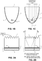
- Fig. 1b shows several aspects of an example composite overcoating structure. This is a section view in a transverse plane (transverse to the longitudinal axis 2 of the fiber 6), with Fig. 1c illustrating the side-emitted light emerging from the embedded fiber 6.
- the light transmissive part 3 has a flat or entirely horizontal top layer 7 (or top surface 7), which is not covered by the reflective part 4 and through which the concentrated or redirected side-emitted light emerges, e.g., into air that surrounds the light source.
- the overcoating structure may have left-right reflection symmetry across a vertical, longitudinal plane 5 (in which the center longitudinal axis 2 lies.)
- the light transmissive part 3 has a "parabolic" shape, and where the reflective part 4 is formed as a layer that covers and conforms to the bottom surface of the light transmissive part 3, while the latter's top surface (or top layer) 7 is not covered, as shown; the light gathering function of the composite lighting structure is however not limited to this shape.
- Any alternative shape for the reflective part 4 (and its conforming, bottom surface of the light transmissive part 3) that concentrates the light emerging from the side of the fiber 6 (e.g., as in Fig. 1b ) in a preferred direction may be possible, such as a U-shape (see Fig.
- the entirety of the outer side surface of the light transmissive part 3 (having any one of the above shapes), or its complete side circumference, is divided into two, contiguous sections, namely the top surface or top layer 7, and the rest which is referred to here as the bottom surface.
- the bottom surface may be curved and covered in its entirety by the reflective part 4, but the top surface is not curved (flat) and is not covered at all by the reflective part 4.
- Fig. 1b shows the interaction of the light that emerges from the side of optical fiber, with the overcoating, in a plane transverse to the longitudinal axis 2 of the fiber 6.
- the longitudinal axis 2 of the optical fiber 6 in this example is substantially positioned on a vertical symmetry axis (lying in the vertical longitudinal plane 5) of the parabolic shape, in the vicinity of the focus of the parabola (that is defined by the bottom surface).
- light emerging from the lengthwise segment 9 of the fiber 6 is redirected by the reflective part 4 in a transverse direction, and, especially due to the asymmetric shape of the reflective part 4.
- the redirected light emerges from the composite structure from only the top layer or surface 7 of the composite lighting structure (due to the entirety of the bottom surface being covered by the reflective part 4).
- Fig. 2a and Fig. 2b show another composite structure in a section view in a longitudinal plan, but where the top layer 7 is mechanically structured into a "prismatic lens" (or simply, prismatic) structure 10 (although the light redirection and/or recycling function of the mechanical structure is not limited to a prismatic lens - see for example Fig. 3a and Fig. 4b .
- a goal here is to redirect and recycle the light that is emerging transversely from the fiber 6 and that reaches the top surface of the light transmissive part 3, so as to become more collimated as it emerges outward, and along the length of the fiber 6.
- the prismatic structure 10 may have any suitable combination of adjacently placed, prism cells or conical cells, each of which may be tilted relative to the vertical, e.g. a one-dimensional array of adjacently placed, tilted prism cells, or other types of prism cells that are arranged to form a prismatic lens that achieves a particular light beam redirection function.
- each individual prism cell is elongated in the transverse direction as seen in Fig. 2c , and the prism cells are positioned or oriented side by side (not end to end) in the longitudinal direction as seen in Fig. 2a and in Fig. 2b .
- the prism cells may not be elongated, e.g., they may be squares.
- the prismatic structure 10 may be made of a suitable light transmissive material, which may be different than that of the light transmissive part 3 which is joined directly below; it may be made as separate piece (of which the top surface or top layer 7 is a part) that is then joined to a flat top surface of the light transmissive part 3.
- Fig. 2b shows the interaction between light that emerges from the side of the optical fiber 6 and the composite overcoating, in a plan longitudinal to the fiber 6. Light emerging from the fiber may be directly redirected by refraction at the air-prism interface which is indicated as (1) in the figure, and it may also be indirectly redirected, i.e. undergoing several reflections inside the composite lighting structure before leaving it, indicated as (2) in the figure.
- Fig. 2c shows the composite structure of Fig. 2a in a section view in a transverse plane.
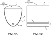
- Fig. 3a shows a section view in a transverse plane of a composite overcoating structure having a microlens array structure 12 at its top surface 7.
- Fig. 3b shows a section view in a vertical longitudinal plane, of the composite overcoating structure of Fig. 3a .
- each individual microlens is elongated in the transverse direction as seen in Fig. 3a , and the microlenses are positioned or oriented side by side (not end to end) in the longitudinal direction as seen in Fig. 3b .
- the individual microlenses of the microlens structure 12 are said to "selectively" focus or homogenize the side-emitted light out of the overcoating structure, in contrast to the single continuous lens structure 14 shown in Fig.
- the microlens array structure 12 and the single continuous lens structure 14 may each be made of a suitable light transmissive material, which may be different than that of the light transmissive part 3 which is joined directly below; each may be made as separate piece (of which the top surface of top layer 7 is a part) that is then joined to a flat top surface of the light transmissive part 3.
- Fig. 5 and Fig. 6 show further aspects of an embodiment of the composite structure, where different examples of a bottom part of the composite structure are shown that can serve to more easily affix the light source as part of a larger system.
- Fig. 5 shows a polygon shaped or polygonal bottom part 16, which on one side conforms to the outer face of the reflective part 4 while on the opposite side is polygon shaped (here, having a left corner joined by a straight section to a right corner, although other polygonal shapes are possible.)
- the polygonal shape enables use of the bottom part 16 as a keyed structure, to fit the light source into a mating, keyed receptacle of the system.
- Fig. 6 shows the combination of the structure of Fig.
- knobs 17 are affixed to the outer face of the polygonal bottom part 16 and extend outward therefrom.
- the knobs 17 can serve to affix the light source to a system.
- the knobs can be made of the same material as the polygonal bottom part 16 such that they form a single or integral part of the light source.
- the knobs 17 can be separately formed pieces that are bonded to or inserted into the polygonal bottom part 16, e.g., prior to a polymerization process that yields the precise boundary of the outside face of the polygonal bottom part 16.
- Figs. 2a-2c show the prismatic lens structure composed of elongated prism cells arranged side by side in a sequence that extends in the longitudinal plane
- an alternative may be to orient the prism cells side by side in a sequence extending in the transverse plane. The description is thus to be regarded as illustrative instead of limiting.
Landscapes
- Physics & Mathematics (AREA)
- Engineering & Computer Science (AREA)
- General Engineering & Computer Science (AREA)
- General Physics & Mathematics (AREA)
- Optics & Photonics (AREA)
- Light Guides In General And Applications Therefor (AREA)
- Planar Illumination Modules (AREA)
- Non-Portable Lighting Devices Or Systems Thereof (AREA)
Claims (15)
- Eine Verbundstruktur mit einer eingebetteten, seitenemittierenden optischen Faser mit:einer optischen Faser (6) mit einem längsgerichteten Segment (9), in dem eine streuende Struktur ausgebildet ist, die ausgehendes Primärlicht in der Faser seitlich aus der optischen Faser (6) leitet, und einer in die optische Faser (6) integrierten, aktiv nachleuchtenden Schicht, die die Wellenlänge des ausgehenden Primärlichts in Sekundärlicht umwandelt, wobei das Sekundärlicht seitlich von einer äußeren Seitenfläche des längsgerichteten Segments (9) der optischen Faser (6) emittiert wird, undeiner auf der äußeren Seitenfläche des längsgerichteten Segments (9) der optischen Faser (6) ausgebildeten Verbunddeckschicht mit (i) einem inaktiv lichtdurchlässigen Material (3), das die Wellenlänge nicht umwandelt, auf der äußeren Seitenfläche des längsgerichteten Segments der optischen Faser (6) ausgebildet ist und diese vollständig umgibt, und (ii) einer lichtreflektierenden Schicht (4), die mit Ausnahme einer obersten Schicht (7) des inaktiv lichtdurchlässigen Materials (3) auf einer äußeren Seitenfläche des inaktiv lichtdurchlässigen Materials (3) ausgebildet ist, wobei die Verbunddeckschicht eine asymmetrische Form um eine längliche Mittelachse (2) der optischen Faser (6) bildet, so dass das seitenemittierte Licht aus der optischen Faser (6) von der reflektierenden Schicht (4) vorzugsweise in einer Querrichtung reflektiert wird, so dass es über die oberste Schicht (7) des inaktiv lichtdurchlässigen Materials (3) aus der Verbundstruktur austritt.
- Die Verbundstruktur gemäß Anspruch 1, wobei ein Querschnitt der lichtreflektierenden Schicht (4) in Querebene eine Parabel beschreibt und das längsgerichtete Segment der optischen Faser (6) in der Nähe des Schwerpunkts der Parabel liegt.
- Die Verbundstruktur gemäß Anspruch 1, wobei ein Querschnitt der lichtreflektierenden Schicht (4) in Querebene einen Teilkreis, eine Ellipse oder eine Hyperbel beschreibt.
- Die Verbundstruktur gemäß Anspruch 1, wobei ein Querschnitt der lichtreflektierenden Schicht (4) in Querebene eine Linie beschreibt, die eine Mehrzahl von Linienabschnitten unterschiedlicher Krümmung umfasst.
- Die Verbundstruktur gemäß Anspruch 1, wobei ein Querschnitt der lichtreflektierenden Schicht (4) in Querebene eine Linie beschreibt, die eine Mehrzahl gerader, an den Enden verbundener Linienabschnitte umfasst.
- Die Verbundstruktur gemäß Anspruch 1, wobei die oberste Schicht (7) des inaktiven, lichtdurchlässigen Bereichs (3) eine Mehrzahl von Prismen (10) aufweist, die seitlich zueinander und nicht an den Enden verbunden in Richtung der Längsachse (2) der optischen Faser (6) angeordnet sind.
- Die Verbundstruktur gemäß Anspruch 1, wobei die oberste Schicht (7) des inaktiven, lichtdurchlässigen Bereichs (3) eine Mehrzahl von Mikrolinsen (12) aufweist, die in einer Längsebene oder einer Querebene angeordnet sind.
- Die Verbundstruktur gemäß Anspruch 1, wobei die oberste Schicht (7) des inaktiven, lichtdurchlässigen Bereichs (3) eine einzige konvexe Linse (14) in einer Längsebene oder einer Querebene aufweist.
- Die Verbundstruktur gemäß Anspruch 1, wobei die Verbunddeckschicht weiterhin einen unteren Bereich (16) aufweist, dessen eine Seite sich an eine untere Oberfläche der lichtreflektierenden Schicht (4) anpasst und in Kontakt zu ihr steht und dessen andere Seite in einer Längsebene oder einer Querebene vieleckig geformt ist.
- Die Verbundstruktur gemäß Anspruch 9, die weiterhin eine Mehrzahl von Noppen (17) aufweist, die am unteren Bereich (16) angebracht sind und aus diesem hervorstehen.
- Die Verbundstruktur gemäß Anspruch 10, wobei die Noppen (17) aus dem gleichen Material wie der untere Bereich (16) der Verbunddeckschicht bestehen oder als integraler Bestandteil des unteren Abschnitts (16) ausgeformt sind oder
wobei die Noppen (17) im Vergleich zum unteren Bereich (16) als separate Teile ausgebildet sind und am unteren Bereich (16) haften. - Eine Beleuchtung mit:einer optischen Faser (6) mit einem längsgerichteten Segment (9), in dem eine streuende Struktur ausgebildet ist, die ausgehendes Primärlicht in der optischen Faser (6) seitlich aus der optischen Faser (6) leitet, und einer in die optische Faser (6) integrierten, aktiv nachleuchtenden Schicht, die die Wellenlänge des ausgehenden Primärlichts in Sekundärlicht umwandelt,einem festen Körper (3) aus einem inaktiven, lichtdurchlässigen Material, wobei das längsgerichtete Segment (9) der optischen Faser (6) innerhalb des festen Körpers (3) liegt und vollständig mit der Längsachse (2) des festen Körpers (3) übereinstimmt, wobei das Sekundärlicht von einer Seitenfläche des längsgerichteten Segments (9) der optischen Faser (6) in den festen Körper (3) emittiert wird undeinem externen Reflektor (4) mit einer gekrümmten, lichtreflektierenden Oberfläche, die sich an einen Bereich der Seitenfläche des festen Körpers (3) anpasst und sich an sie anlegt, während ein anderer Bereich (7) des festen Körpers (3) unbedeckt bleibt,wobei der feste Körper (3) im Wesentlichen zylindrisch, aber nicht drehsymmetrisch zur inneren Längsachse (2) oder zum Dorn des festen Körpers (3) ist und der Bereich der Seitenfläche, auf der der externe Reflektor (4) ausgebildet ist, sich von einer naheliegenden Fläche des festen Körpers (3) so erstreckt, dass das Sekundärlicht vom externen Reflektor (4) in vorzugsweise Querrichtung reflektiert wird, so dass es aus dem anderen Bereich (7) des festen Körpers (3) wieder austritt.
- Die Beleuchtung gemäß Anspruch 12, wobei ein Querschnitt des externen Reflektors (4) in Querebene zur Längsachse (2) eine Parabel beschreibt und der Schnittpunkt von Querebene und längsgerichtetem Segment (9) der optischen Faser (6) sich im Schwerpunkt der Parabel befindet.
- Die Beleuchtung gemäß Anspruch 12 oder 13, wobei der externe Reflektor (4) den überwiegenden Teil des gesamten Bereichs der Seitenfläche des festen Körpers (3) bedeckt.
- Die Beleuchtung gemäß einem der Ansprüche 12-14, wobei besagter anderer, vom externen Reflektor (4) unbedeckter Bereich (7) des festen Körpers (3) eben ist oder wobei besagter anderer, vom externen Reflektor (4) unbedeckter Bereich (7) des festen Körpers (3) im Wesentlichen ebenflächig mit einer Schicht von Mikrolinsen (12) ist oder
wobei besagter anderer, vom externen Reflektor (4) unbedeckter Bereich (7) des festen Körpers (3) im Wesentlichen ebenflächig mit einer Schicht von Prismen (10) ist, durch die das umgeleitete sekundäre Licht austritt.
Applications Claiming Priority (2)
| Application Number | Priority Date | Filing Date | Title |
|---|---|---|---|
| US201562268815P | 2015-12-17 | 2015-12-17 | |
| PCT/IB2016/057738 WO2017103889A1 (en) | 2015-12-17 | 2016-12-16 | Optical fiber light source with composite overcoating structure |
Publications (2)
| Publication Number | Publication Date |
|---|---|
| EP3390904A1 EP3390904A1 (de) | 2018-10-24 |
| EP3390904B1 true EP3390904B1 (de) | 2021-04-21 |
Family
ID=57838430
Family Applications (1)
| Application Number | Title | Priority Date | Filing Date |
|---|---|---|---|
| EP16828776.1A Active EP3390904B1 (de) | 2015-12-17 | 2016-12-16 | Glasfaserlichtquelle mit zusammengesetzter deckschichtstruktur |
Country Status (6)
| Country | Link |
|---|---|
| US (4) | US11061177B2 (de) |
| EP (1) | EP3390904B1 (de) |
| JP (2) | JP6585848B2 (de) |
| CN (2) | CN108368992B (de) |
| ES (1) | ES2877683T3 (de) |
| WO (1) | WO2017103889A1 (de) |
Families Citing this family (3)
| Publication number | Priority date | Publication date | Assignee | Title |
|---|---|---|---|---|
| EP3390904B1 (de) * | 2015-12-17 | 2021-04-21 | L.E.S.S. Ltd | Glasfaserlichtquelle mit zusammengesetzter deckschichtstruktur |
| US12228761B2 (en) | 2019-12-20 | 2025-02-18 | L.E.S.S. Ltd | Optical waveguide-based side illuminating assembly, elongated reinforcing structure, and receptacle |
| EP4378633A3 (de) | 2021-03-22 | 2024-11-06 | Guido Valentini | Handwerkzeugmaschine mit einem werkzeuggehäuse mit einer länglichen lichtemittierenden vorrichtung |
Family Cites Families (28)
| Publication number | Priority date | Publication date | Assignee | Title |
|---|---|---|---|---|
| DD208871A1 (de) * | 1982-07-27 | 1984-04-11 | Michael Schreiter | Fokussieranordnung fuer spiegelteleskope |
| JPH071426U (ja) | 1992-09-28 | 1995-01-10 | 多摩電気工業株式会社 | 背面照光装置 |
| US5937127A (en) * | 1996-05-17 | 1999-08-10 | Lumenyte International, Inc. | Linear light form with multilayered jacketing |
| US5905837A (en) * | 1997-07-22 | 1999-05-18 | Nec Usa, Inc. | Side emitting optical fiber |
| US6123442A (en) | 1997-10-24 | 2000-09-26 | Minnesota Mining And Manufacturing Company | Articles with diffuse reflection of light from light fibers |
| DE69927165T2 (de) * | 1998-07-29 | 2006-06-14 | Court Of Napier University Edi | Optische Faser für Anzeigeanwendungen |
| JP2000292786A (ja) | 1999-04-05 | 2000-10-20 | Hitachi Ltd | 線状光源およびこの線状光源を用いた液晶表示装置 |
| JP2003115209A (ja) | 2001-10-04 | 2003-04-18 | Sanyo Electric Co Ltd | 線状導光体を用いた線状照明装置並びに面状照明装置 |
| JP4089258B2 (ja) | 2002-03-26 | 2008-05-28 | 松下電工株式会社 | 照明器具 |
| CN1676990A (zh) * | 2004-03-31 | 2005-10-05 | 黄迎庆 | 一种线性光源 |
| WO2006051475A1 (en) * | 2004-11-15 | 2006-05-18 | Koninklijke Philips Electronics N.V. | Fluorescent light source and a display device comprising such a light source |
| DE102006061164B4 (de) * | 2006-12-22 | 2018-12-27 | Osram Opto Semiconductors Gmbh | Lichtemittierende Vorrichtung |
| US8750671B1 (en) * | 2009-04-16 | 2014-06-10 | Fusion Optix, Inc | Light bulb with omnidirectional output |
| JP5619160B2 (ja) * | 2009-07-31 | 2014-11-05 | ペールプリュス ベスローテン フェノーツハップPeer+ B.V. | 発光光学素子および当該発光光学素子を備える太陽電池システム |
| JP5375424B2 (ja) | 2009-08-10 | 2013-12-25 | 東芝ライテック株式会社 | 発光装置及びその製造方法、灯具、並びに灯具システム |
| JP5486275B2 (ja) | 2009-11-25 | 2014-05-07 | パナソニック液晶ディスプレイ株式会社 | 液晶表示装置 |
| US9441811B2 (en) * | 2010-08-20 | 2016-09-13 | Research Triangle Institute | Lighting devices utilizing optical waveguides and remote light converters, and related methods |
| CN102313992B (zh) * | 2011-03-25 | 2014-06-04 | 明基电通有限公司 | 光传导装置及背光装置 |
| US8724942B2 (en) | 2011-04-26 | 2014-05-13 | Corning Incorporated | Light-coupling optical systems and methods employing light-diffusing optical fiber |
| JP6228110B2 (ja) * | 2011-04-28 | 2017-11-08 | エル イー エス エス・リミテッド | 照明システム用の導波路装置 |
| US9217826B2 (en) * | 2011-10-11 | 2015-12-22 | Corning Incorporated | Multi-wavelength light source using light diffusing fibers |
| JP2013225473A (ja) | 2012-03-21 | 2013-10-31 | Toshiba Lighting & Technology Corp | 発光装置 |
| WO2013191690A1 (en) * | 2012-06-20 | 2013-12-27 | Energy Focus, Inc. | An elongated led lighting arrangement |
| US9254785B2 (en) | 2013-02-14 | 2016-02-09 | Ford Global Technologies, Llc | Extruded light pipe carrier |
| JP5792854B1 (ja) | 2014-03-25 | 2015-10-14 | 株式会社藤商事 | 遊技機 |
| CN104676387A (zh) * | 2015-03-24 | 2015-06-03 | 深圳市华星光电技术有限公司 | 光纤背光模组及液晶显示器 |
| US20170115442A1 (en) * | 2015-10-26 | 2017-04-27 | Ford Global Technologies, Llc | Extruded fiber optic light bar |
| EP3390904B1 (de) * | 2015-12-17 | 2021-04-21 | L.E.S.S. Ltd | Glasfaserlichtquelle mit zusammengesetzter deckschichtstruktur |
-
2016
- 2016-12-16 EP EP16828776.1A patent/EP3390904B1/de active Active
- 2016-12-16 WO PCT/IB2016/057738 patent/WO2017103889A1/en not_active Ceased
- 2016-12-16 US US16/063,146 patent/US11061177B2/en active Active
- 2016-12-16 CN CN201680074198.5A patent/CN108368992B/zh active Active
- 2016-12-16 CN CN202010968068.4A patent/CN112198582B/zh active Active
- 2016-12-16 ES ES16828776T patent/ES2877683T3/es active Active
- 2016-12-16 JP JP2018530790A patent/JP6585848B2/ja active Active
-
2019
- 2019-09-05 JP JP2019161786A patent/JP6866442B2/ja active Active
-
2021
- 2021-06-28 US US17/361,206 patent/US11719873B2/en active Active
-
2023
- 2023-06-30 US US18/345,860 patent/US12242096B2/en active Active
-
2025
- 2025-02-14 US US19/054,639 patent/US12674926B2/en active Active
Non-Patent Citations (1)
| Title |
|---|
| None * |
Also Published As
| Publication number | Publication date |
|---|---|
| US12674926B2 (en) | 2026-07-07 |
| HK1254781A1 (en) | 2019-07-26 |
| US20190004230A1 (en) | 2019-01-03 |
| WO2017103889A1 (en) | 2017-06-22 |
| US12242096B2 (en) | 2025-03-04 |
| US20230341602A1 (en) | 2023-10-26 |
| US20250244514A1 (en) | 2025-07-31 |
| ES2877683T3 (es) | 2021-11-17 |
| JP2019505950A (ja) | 2019-02-28 |
| JP6585848B2 (ja) | 2019-10-02 |
| CN108368992A (zh) | 2018-08-03 |
| CN108368992B (zh) | 2020-10-13 |
| EP3390904A1 (de) | 2018-10-24 |
| US11061177B2 (en) | 2021-07-13 |
| US11719873B2 (en) | 2023-08-08 |
| JP6866442B2 (ja) | 2021-04-28 |
| CN112198582B (zh) | 2024-08-23 |
| CN112198582A (zh) | 2021-01-08 |
| US20210382219A1 (en) | 2021-12-09 |
| JP2019207892A (ja) | 2019-12-05 |
Similar Documents
| Publication | Publication Date | Title |
|---|---|---|
| US12242096B2 (en) | Optical fiber light source with composite overcoating structure | |
| EP2334980B1 (de) | Kompaktes optisches system und linsen zur erzeugung von gleichförmigem kollimiertem licht | |
| US8434913B2 (en) | Round illumination device | |
| US9442241B2 (en) | Optics for illumination devices | |
| US9753210B2 (en) | Optical waveguide body | |
| WO2013009670A2 (en) | Lighting assembly with controlled configurable light redirection | |
| US20120170260A1 (en) | Off-axis illumination led luminaire | |
| US9170364B2 (en) | Lighting assembly with a light guide having light-redirecting edge features | |
| WO2015103522A1 (en) | Shell integrator | |
| US10451247B2 (en) | Optic and apparatus for making an optic | |
| US20230008568A1 (en) | Lighting and/or signaling device for a motor vehicle and a light guide therefor | |
| JP2019207892A5 (de) | ||
| HK1254781B (en) | Optical fiber light source with composite overcoating structure | |
| HK40042527A (en) | Composite structure and lighting structure | |
| HK40042527B (en) | Composite structure and lighting structure | |
| TW201226805A (en) | Lighting assembly with cornuate light guide | |
| CN206222241U (zh) | 用于修改光分布的光学设备 |
Legal Events
| Date | Code | Title | Description |
|---|---|---|---|
| STAA | Information on the status of an ep patent application or granted ep patent |
Free format text: STATUS: UNKNOWN |
|
| STAA | Information on the status of an ep patent application or granted ep patent |
Free format text: STATUS: THE INTERNATIONAL PUBLICATION HAS BEEN MADE |
|
| PUAI | Public reference made under article 153(3) epc to a published international application that has entered the european phase |
Free format text: ORIGINAL CODE: 0009012 |
|
| STAA | Information on the status of an ep patent application or granted ep patent |
Free format text: STATUS: REQUEST FOR EXAMINATION WAS MADE |
|
| 17P | Request for examination filed |
Effective date: 20180530 |
|
| AK | Designated contracting states |
Kind code of ref document: A1 Designated state(s): AL AT BE BG CH CY CZ DE DK EE ES FI FR GB GR HR HU IE IS IT LI LT LU LV MC MK MT NL NO PL PT RO RS SE SI SK SM TR |
|
| AX | Request for extension of the european patent |
Extension state: BA ME |
|
| DAV | Request for validation of the european patent (deleted) | ||
| DAX | Request for extension of the european patent (deleted) | ||
| REG | Reference to a national code |
Ref country code: HK Ref legal event code: DE Ref document number: 1254781 Country of ref document: HK |
|
| STAA | Information on the status of an ep patent application or granted ep patent |
Free format text: STATUS: EXAMINATION IS IN PROGRESS |
|
| 17Q | First examination report despatched |
Effective date: 20200710 |
|
| GRAP | Despatch of communication of intention to grant a patent |
Free format text: ORIGINAL CODE: EPIDOSNIGR1 |
|
| STAA | Information on the status of an ep patent application or granted ep patent |
Free format text: STATUS: GRANT OF PATENT IS INTENDED |
|
| INTG | Intention to grant announced |
Effective date: 20201123 |
|
| GRAS | Grant fee paid |
Free format text: ORIGINAL CODE: EPIDOSNIGR3 |
|
| GRAA | (expected) grant |
Free format text: ORIGINAL CODE: 0009210 |
|
| STAA | Information on the status of an ep patent application or granted ep patent |
Free format text: STATUS: THE PATENT HAS BEEN GRANTED |
|
| AK | Designated contracting states |
Kind code of ref document: B1 Designated state(s): AL AT BE BG CH CY CZ DE DK EE ES FI FR GB GR HR HU IE IS IT LI LT LU LV MC MK MT NL NO PL PT RO RS SE SI SK SM TR |
|
| REG | Reference to a national code |
Ref country code: GB Ref legal event code: FG4D |
|
| REG | Reference to a national code |
Ref country code: CH Ref legal event code: EP |
|
| REG | Reference to a national code |
Ref country code: DE Ref legal event code: R096 Ref document number: 602016056622 Country of ref document: DE |
|
| REG | Reference to a national code |
Ref country code: IE Ref legal event code: FG4D |
|
| REG | Reference to a national code |
Ref country code: AT Ref legal event code: REF Ref document number: 1385002 Country of ref document: AT Kind code of ref document: T Effective date: 20210515 |
|
| REG | Reference to a national code |
Ref country code: LT Ref legal event code: MG9D |
|
| REG | Reference to a national code |
Ref country code: AT Ref legal event code: MK05 Ref document number: 1385002 Country of ref document: AT Kind code of ref document: T Effective date: 20210421 |
|
| REG | Reference to a national code |
Ref country code: NL Ref legal event code: MP Effective date: 20210421 |
|
| PG25 | Lapsed in a contracting state [announced via postgrant information from national office to epo] |
Ref country code: FI Free format text: LAPSE BECAUSE OF FAILURE TO SUBMIT A TRANSLATION OF THE DESCRIPTION OR TO PAY THE FEE WITHIN THE PRESCRIBED TIME-LIMIT Effective date: 20210421 Ref country code: LT Free format text: LAPSE BECAUSE OF FAILURE TO SUBMIT A TRANSLATION OF THE DESCRIPTION OR TO PAY THE FEE WITHIN THE PRESCRIBED TIME-LIMIT Effective date: 20210421 Ref country code: NL Free format text: LAPSE BECAUSE OF FAILURE TO SUBMIT A TRANSLATION OF THE DESCRIPTION OR TO PAY THE FEE WITHIN THE PRESCRIBED TIME-LIMIT Effective date: 20210421 Ref country code: AT Free format text: LAPSE BECAUSE OF FAILURE TO SUBMIT A TRANSLATION OF THE DESCRIPTION OR TO PAY THE FEE WITHIN THE PRESCRIBED TIME-LIMIT Effective date: 20210421 Ref country code: BG Free format text: LAPSE BECAUSE OF FAILURE TO SUBMIT A TRANSLATION OF THE DESCRIPTION OR TO PAY THE FEE WITHIN THE PRESCRIBED TIME-LIMIT Effective date: 20210721 Ref country code: HR Free format text: LAPSE BECAUSE OF FAILURE TO SUBMIT A TRANSLATION OF THE DESCRIPTION OR TO PAY THE FEE WITHIN THE PRESCRIBED TIME-LIMIT Effective date: 20210421 |
|
| REG | Reference to a national code |
Ref country code: ES Ref legal event code: FG2A Ref document number: 2877683 Country of ref document: ES Kind code of ref document: T3 Effective date: 20211117 |
|
| PG25 | Lapsed in a contracting state [announced via postgrant information from national office to epo] |
Ref country code: LV Free format text: LAPSE BECAUSE OF FAILURE TO SUBMIT A TRANSLATION OF THE DESCRIPTION OR TO PAY THE FEE WITHIN THE PRESCRIBED TIME-LIMIT Effective date: 20210421 Ref country code: GR Free format text: LAPSE BECAUSE OF FAILURE TO SUBMIT A TRANSLATION OF THE DESCRIPTION OR TO PAY THE FEE WITHIN THE PRESCRIBED TIME-LIMIT Effective date: 20210722 Ref country code: IS Free format text: LAPSE BECAUSE OF FAILURE TO SUBMIT A TRANSLATION OF THE DESCRIPTION OR TO PAY THE FEE WITHIN THE PRESCRIBED TIME-LIMIT Effective date: 20210821 Ref country code: SE Free format text: LAPSE BECAUSE OF FAILURE TO SUBMIT A TRANSLATION OF THE DESCRIPTION OR TO PAY THE FEE WITHIN THE PRESCRIBED TIME-LIMIT Effective date: 20210421 Ref country code: RS Free format text: LAPSE BECAUSE OF FAILURE TO SUBMIT A TRANSLATION OF THE DESCRIPTION OR TO PAY THE FEE WITHIN THE PRESCRIBED TIME-LIMIT Effective date: 20210421 Ref country code: PT Free format text: LAPSE BECAUSE OF FAILURE TO SUBMIT A TRANSLATION OF THE DESCRIPTION OR TO PAY THE FEE WITHIN THE PRESCRIBED TIME-LIMIT Effective date: 20210823 Ref country code: PL Free format text: LAPSE BECAUSE OF FAILURE TO SUBMIT A TRANSLATION OF THE DESCRIPTION OR TO PAY THE FEE WITHIN THE PRESCRIBED TIME-LIMIT Effective date: 20210421 Ref country code: NO Free format text: LAPSE BECAUSE OF FAILURE TO SUBMIT A TRANSLATION OF THE DESCRIPTION OR TO PAY THE FEE WITHIN THE PRESCRIBED TIME-LIMIT Effective date: 20210721 |
|
| REG | Reference to a national code |
Ref country code: DE Ref legal event code: R097 Ref document number: 602016056622 Country of ref document: DE |
|
| PG25 | Lapsed in a contracting state [announced via postgrant information from national office to epo] |
Ref country code: DK Free format text: LAPSE BECAUSE OF FAILURE TO SUBMIT A TRANSLATION OF THE DESCRIPTION OR TO PAY THE FEE WITHIN THE PRESCRIBED TIME-LIMIT Effective date: 20210421 Ref country code: CZ Free format text: LAPSE BECAUSE OF FAILURE TO SUBMIT A TRANSLATION OF THE DESCRIPTION OR TO PAY THE FEE WITHIN THE PRESCRIBED TIME-LIMIT Effective date: 20210421 Ref country code: EE Free format text: LAPSE BECAUSE OF FAILURE TO SUBMIT A TRANSLATION OF THE DESCRIPTION OR TO PAY THE FEE WITHIN THE PRESCRIBED TIME-LIMIT Effective date: 20210421 Ref country code: RO Free format text: LAPSE BECAUSE OF FAILURE TO SUBMIT A TRANSLATION OF THE DESCRIPTION OR TO PAY THE FEE WITHIN THE PRESCRIBED TIME-LIMIT Effective date: 20210421 Ref country code: SM Free format text: LAPSE BECAUSE OF FAILURE TO SUBMIT A TRANSLATION OF THE DESCRIPTION OR TO PAY THE FEE WITHIN THE PRESCRIBED TIME-LIMIT Effective date: 20210421 Ref country code: SK Free format text: LAPSE BECAUSE OF FAILURE TO SUBMIT A TRANSLATION OF THE DESCRIPTION OR TO PAY THE FEE WITHIN THE PRESCRIBED TIME-LIMIT Effective date: 20210421 |
|
| PLBE | No opposition filed within time limit |
Free format text: ORIGINAL CODE: 0009261 |
|
| STAA | Information on the status of an ep patent application or granted ep patent |
Free format text: STATUS: NO OPPOSITION FILED WITHIN TIME LIMIT |
|
| 26N | No opposition filed |
Effective date: 20220124 |
|
| PG25 | Lapsed in a contracting state [announced via postgrant information from national office to epo] |
Ref country code: IS Free format text: LAPSE BECAUSE OF FAILURE TO SUBMIT A TRANSLATION OF THE DESCRIPTION OR TO PAY THE FEE WITHIN THE PRESCRIBED TIME-LIMIT Effective date: 20210821 Ref country code: AL Free format text: LAPSE BECAUSE OF FAILURE TO SUBMIT A TRANSLATION OF THE DESCRIPTION OR TO PAY THE FEE WITHIN THE PRESCRIBED TIME-LIMIT Effective date: 20210421 |
|
| PG25 | Lapsed in a contracting state [announced via postgrant information from national office to epo] |
Ref country code: MC Free format text: LAPSE BECAUSE OF FAILURE TO SUBMIT A TRANSLATION OF THE DESCRIPTION OR TO PAY THE FEE WITHIN THE PRESCRIBED TIME-LIMIT Effective date: 20210421 |
|
| REG | Reference to a national code |
Ref country code: BE Ref legal event code: MM Effective date: 20211231 |
|
| PG25 | Lapsed in a contracting state [announced via postgrant information from national office to epo] |
Ref country code: LU Free format text: LAPSE BECAUSE OF NON-PAYMENT OF DUE FEES Effective date: 20211216 Ref country code: IE Free format text: LAPSE BECAUSE OF NON-PAYMENT OF DUE FEES Effective date: 20211216 |
|
| PG25 | Lapsed in a contracting state [announced via postgrant information from national office to epo] |
Ref country code: BE Free format text: LAPSE BECAUSE OF NON-PAYMENT OF DUE FEES Effective date: 20211231 |
|
| PG25 | Lapsed in a contracting state [announced via postgrant information from national office to epo] |
Ref country code: HU Free format text: LAPSE BECAUSE OF FAILURE TO SUBMIT A TRANSLATION OF THE DESCRIPTION OR TO PAY THE FEE WITHIN THE PRESCRIBED TIME-LIMIT; INVALID AB INITIO Effective date: 20161216 |
|
| PG25 | Lapsed in a contracting state [announced via postgrant information from national office to epo] |
Ref country code: CY Free format text: LAPSE BECAUSE OF FAILURE TO SUBMIT A TRANSLATION OF THE DESCRIPTION OR TO PAY THE FEE WITHIN THE PRESCRIBED TIME-LIMIT Effective date: 20210421 |
|
| PG25 | Lapsed in a contracting state [announced via postgrant information from national office to epo] |
Ref country code: MK Free format text: LAPSE BECAUSE OF FAILURE TO SUBMIT A TRANSLATION OF THE DESCRIPTION OR TO PAY THE FEE WITHIN THE PRESCRIBED TIME-LIMIT Effective date: 20210421 |
|
| PG25 | Lapsed in a contracting state [announced via postgrant information from national office to epo] |
Ref country code: MT Free format text: LAPSE BECAUSE OF FAILURE TO SUBMIT A TRANSLATION OF THE DESCRIPTION OR TO PAY THE FEE WITHIN THE PRESCRIBED TIME-LIMIT Effective date: 20210421 |
|
| PG25 | Lapsed in a contracting state [announced via postgrant information from national office to epo] |
Ref country code: TR Free format text: LAPSE BECAUSE OF FAILURE TO SUBMIT A TRANSLATION OF THE DESCRIPTION OR TO PAY THE FEE WITHIN THE PRESCRIBED TIME-LIMIT Effective date: 20210421 |
|
| REG | Reference to a national code |
Ref country code: CH Ref legal event code: U11 Free format text: ST27 STATUS EVENT CODE: U-0-0-U10-U11 (AS PROVIDED BY THE NATIONAL OFFICE) Effective date: 20260101 |
|
| PGFP | Annual fee paid to national office [announced via postgrant information from national office to epo] |
Ref country code: GB Payment date: 20251229 Year of fee payment: 10 |
|
| PGFP | Annual fee paid to national office [announced via postgrant information from national office to epo] |
Ref country code: IT Payment date: 20251219 Year of fee payment: 10 |
|
| PGFP | Annual fee paid to national office [announced via postgrant information from national office to epo] |
Ref country code: FR Payment date: 20251226 Year of fee payment: 10 |
|
| PGFP | Annual fee paid to national office [announced via postgrant information from national office to epo] |
Ref country code: ES Payment date: 20260102 Year of fee payment: 10 |
|
| PGFP | Annual fee paid to national office [announced via postgrant information from national office to epo] |
Ref country code: DE Payment date: 20251229 Year of fee payment: 10 |
|
| PGFP | Annual fee paid to national office [announced via postgrant information from national office to epo] |
Ref country code: CH Payment date: 20260101 Year of fee payment: 10 |