EP3390879B1 - Laserinduzierte versiegelung von konzentrisch geschichteten materialien - Google Patents
Laserinduzierte versiegelung von konzentrisch geschichteten materialien Download PDFInfo
- Publication number
- EP3390879B1 EP3390879B1 EP16876481.9A EP16876481A EP3390879B1 EP 3390879 B1 EP3390879 B1 EP 3390879B1 EP 16876481 A EP16876481 A EP 16876481A EP 3390879 B1 EP3390879 B1 EP 3390879B1
- Authority
- EP
- European Patent Office
- Prior art keywords
- laser
- layer
- induced seal
- external surface
- induced
- Prior art date
- Legal status (The legal status is an assumption and is not a legal conclusion. Google has not performed a legal analysis and makes no representation as to the accuracy of the status listed.)
- Active
Links
Images



Classifications
-
- B—PERFORMING OPERATIONS; TRANSPORTING
- B29—WORKING OF PLASTICS; WORKING OF SUBSTANCES IN A PLASTIC STATE IN GENERAL
- B29C—SHAPING OR JOINING OF PLASTICS; SHAPING OF MATERIAL IN A PLASTIC STATE, NOT OTHERWISE PROVIDED FOR; AFTER-TREATMENT OF THE SHAPED PRODUCTS, e.g. REPAIRING
- B29C65/00—Joining or sealing of preformed parts, e.g. welding of plastics materials; Apparatus therefor
- B29C65/02—Joining or sealing of preformed parts, e.g. welding of plastics materials; Apparatus therefor by heating, with or without pressure
- B29C65/14—Joining or sealing of preformed parts, e.g. welding of plastics materials; Apparatus therefor by heating, with or without pressure using wave energy, i.e. electromagnetic radiation, or particle radiation
- B29C65/16—Laser beams
-
- B—PERFORMING OPERATIONS; TRANSPORTING
- B29—WORKING OF PLASTICS; WORKING OF SUBSTANCES IN A PLASTIC STATE IN GENERAL
- B29C—SHAPING OR JOINING OF PLASTICS; SHAPING OF MATERIAL IN A PLASTIC STATE, NOT OTHERWISE PROVIDED FOR; AFTER-TREATMENT OF THE SHAPED PRODUCTS, e.g. REPAIRING
- B29C65/00—Joining or sealing of preformed parts, e.g. welding of plastics materials; Apparatus therefor
- B29C65/02—Joining or sealing of preformed parts, e.g. welding of plastics materials; Apparatus therefor by heating, with or without pressure
- B29C65/14—Joining or sealing of preformed parts, e.g. welding of plastics materials; Apparatus therefor by heating, with or without pressure using wave energy, i.e. electromagnetic radiation, or particle radiation
- B29C65/16—Laser beams
- B29C65/1629—Laser beams characterised by the way of heating the interface
- B29C65/1635—Laser beams characterised by the way of heating the interface at least passing through one of the parts to be joined, i.e. laser transmission welding
-
- B—PERFORMING OPERATIONS; TRANSPORTING
- B29—WORKING OF PLASTICS; WORKING OF SUBSTANCES IN A PLASTIC STATE IN GENERAL
- B29C—SHAPING OR JOINING OF PLASTICS; SHAPING OF MATERIAL IN A PLASTIC STATE, NOT OTHERWISE PROVIDED FOR; AFTER-TREATMENT OF THE SHAPED PRODUCTS, e.g. REPAIRING
- B29C65/00—Joining or sealing of preformed parts, e.g. welding of plastics materials; Apparatus therefor
- B29C65/02—Joining or sealing of preformed parts, e.g. welding of plastics materials; Apparatus therefor by heating, with or without pressure
- B29C65/14—Joining or sealing of preformed parts, e.g. welding of plastics materials; Apparatus therefor by heating, with or without pressure using wave energy, i.e. electromagnetic radiation, or particle radiation
- B29C65/16—Laser beams
- B29C65/1629—Laser beams characterised by the way of heating the interface
- B29C65/1654—Laser beams characterised by the way of heating the interface scanning at least one of the parts to be joined
-
- B—PERFORMING OPERATIONS; TRANSPORTING
- B29—WORKING OF PLASTICS; WORKING OF SUBSTANCES IN A PLASTIC STATE IN GENERAL
- B29C—SHAPING OR JOINING OF PLASTICS; SHAPING OF MATERIAL IN A PLASTIC STATE, NOT OTHERWISE PROVIDED FOR; AFTER-TREATMENT OF THE SHAPED PRODUCTS, e.g. REPAIRING
- B29C65/00—Joining or sealing of preformed parts, e.g. welding of plastics materials; Apparatus therefor
- B29C65/02—Joining or sealing of preformed parts, e.g. welding of plastics materials; Apparatus therefor by heating, with or without pressure
- B29C65/14—Joining or sealing of preformed parts, e.g. welding of plastics materials; Apparatus therefor by heating, with or without pressure using wave energy, i.e. electromagnetic radiation, or particle radiation
- B29C65/16—Laser beams
- B29C65/1687—Laser beams making use of light guides
-
- B—PERFORMING OPERATIONS; TRANSPORTING
- B29—WORKING OF PLASTICS; WORKING OF SUBSTANCES IN A PLASTIC STATE IN GENERAL
- B29C—SHAPING OR JOINING OF PLASTICS; SHAPING OF MATERIAL IN A PLASTIC STATE, NOT OTHERWISE PROVIDED FOR; AFTER-TREATMENT OF THE SHAPED PRODUCTS, e.g. REPAIRING
- B29C66/00—General aspects of processes or apparatus for joining preformed parts
- B29C66/01—General aspects dealing with the joint area or with the area to be joined
- B29C66/05—Particular design of joint configurations
- B29C66/10—Particular design of joint configurations particular design of the joint cross-sections
- B29C66/11—Joint cross-sections comprising a single joint-segment, i.e. one of the parts to be joined comprising a single joint-segment in the joint cross-section
- B29C66/112—Single lapped joints
- B29C66/1122—Single lap to lap joints, i.e. overlap joints
-
- B—PERFORMING OPERATIONS; TRANSPORTING
- B29—WORKING OF PLASTICS; WORKING OF SUBSTANCES IN A PLASTIC STATE IN GENERAL
- B29C—SHAPING OR JOINING OF PLASTICS; SHAPING OF MATERIAL IN A PLASTIC STATE, NOT OTHERWISE PROVIDED FOR; AFTER-TREATMENT OF THE SHAPED PRODUCTS, e.g. REPAIRING
- B29C66/00—General aspects of processes or apparatus for joining preformed parts
- B29C66/01—General aspects dealing with the joint area or with the area to be joined
- B29C66/05—Particular design of joint configurations
- B29C66/305—Decorative or coloured joints
-
- B—PERFORMING OPERATIONS; TRANSPORTING
- B29—WORKING OF PLASTICS; WORKING OF SUBSTANCES IN A PLASTIC STATE IN GENERAL
- B29C—SHAPING OR JOINING OF PLASTICS; SHAPING OF MATERIAL IN A PLASTIC STATE, NOT OTHERWISE PROVIDED FOR; AFTER-TREATMENT OF THE SHAPED PRODUCTS, e.g. REPAIRING
- B29C66/00—General aspects of processes or apparatus for joining preformed parts
- B29C66/50—General aspects of joining tubular articles; General aspects of joining long products, i.e. bars or profiled elements; General aspects of joining single elements to tubular articles, hollow articles or bars; General aspects of joining several hollow-preforms to form hollow or tubular articles
- B29C66/51—Joining tubular articles, profiled elements or bars; Joining single elements to tubular articles, hollow articles or bars; Joining several hollow-preforms to form hollow or tubular articles
- B29C66/52—Joining tubular articles, bars or profiled elements
- B29C66/522—Joining tubular articles
- B29C66/5221—Joining tubular articles for forming coaxial connections, i.e. the tubular articles to be joined forming a zero angle relative to each other
-
- B—PERFORMING OPERATIONS; TRANSPORTING
- B29—WORKING OF PLASTICS; WORKING OF SUBSTANCES IN A PLASTIC STATE IN GENERAL
- B29C—SHAPING OR JOINING OF PLASTICS; SHAPING OF MATERIAL IN A PLASTIC STATE, NOT OTHERWISE PROVIDED FOR; AFTER-TREATMENT OF THE SHAPED PRODUCTS, e.g. REPAIRING
- B29C66/00—General aspects of processes or apparatus for joining preformed parts
- B29C66/50—General aspects of joining tubular articles; General aspects of joining long products, i.e. bars or profiled elements; General aspects of joining single elements to tubular articles, hollow articles or bars; General aspects of joining several hollow-preforms to form hollow or tubular articles
- B29C66/51—Joining tubular articles, profiled elements or bars; Joining single elements to tubular articles, hollow articles or bars; Joining several hollow-preforms to form hollow or tubular articles
- B29C66/53—Joining single elements to tubular articles, hollow articles or bars
- B29C66/534—Joining single elements to open ends of tubular or hollow articles or to the ends of bars
- B29C66/5344—Joining single elements to open ends of tubular or hollow articles or to the ends of bars said single elements being substantially annular, i.e. of finite length, e.g. joining flanges to tube ends
-
- B—PERFORMING OPERATIONS; TRANSPORTING
- B29—WORKING OF PLASTICS; WORKING OF SUBSTANCES IN A PLASTIC STATE IN GENERAL
- B29C—SHAPING OR JOINING OF PLASTICS; SHAPING OF MATERIAL IN A PLASTIC STATE, NOT OTHERWISE PROVIDED FOR; AFTER-TREATMENT OF THE SHAPED PRODUCTS, e.g. REPAIRING
- B29C66/00—General aspects of processes or apparatus for joining preformed parts
- B29C66/50—General aspects of joining tubular articles; General aspects of joining long products, i.e. bars or profiled elements; General aspects of joining single elements to tubular articles, hollow articles or bars; General aspects of joining several hollow-preforms to form hollow or tubular articles
- B29C66/65—General aspects of joining tubular articles; General aspects of joining long products, i.e. bars or profiled elements; General aspects of joining single elements to tubular articles, hollow articles or bars; General aspects of joining several hollow-preforms to form hollow or tubular articles with a relative motion between the article and the welding tool
-
- B—PERFORMING OPERATIONS; TRANSPORTING
- B29—WORKING OF PLASTICS; WORKING OF SUBSTANCES IN A PLASTIC STATE IN GENERAL
- B29C—SHAPING OR JOINING OF PLASTICS; SHAPING OF MATERIAL IN A PLASTIC STATE, NOT OTHERWISE PROVIDED FOR; AFTER-TREATMENT OF THE SHAPED PRODUCTS, e.g. REPAIRING
- B29C66/00—General aspects of processes or apparatus for joining preformed parts
- B29C66/50—General aspects of joining tubular articles; General aspects of joining long products, i.e. bars or profiled elements; General aspects of joining single elements to tubular articles, hollow articles or bars; General aspects of joining several hollow-preforms to form hollow or tubular articles
- B29C66/65—General aspects of joining tubular articles; General aspects of joining long products, i.e. bars or profiled elements; General aspects of joining single elements to tubular articles, hollow articles or bars; General aspects of joining several hollow-preforms to form hollow or tubular articles with a relative motion between the article and the welding tool
- B29C66/652—General aspects of joining tubular articles; General aspects of joining long products, i.e. bars or profiled elements; General aspects of joining single elements to tubular articles, hollow articles or bars; General aspects of joining several hollow-preforms to form hollow or tubular articles with a relative motion between the article and the welding tool moving the welding tool around the fixed article
-
- B—PERFORMING OPERATIONS; TRANSPORTING
- B29—WORKING OF PLASTICS; WORKING OF SUBSTANCES IN A PLASTIC STATE IN GENERAL
- B29C—SHAPING OR JOINING OF PLASTICS; SHAPING OF MATERIAL IN A PLASTIC STATE, NOT OTHERWISE PROVIDED FOR; AFTER-TREATMENT OF THE SHAPED PRODUCTS, e.g. REPAIRING
- B29C66/00—General aspects of processes or apparatus for joining preformed parts
- B29C66/70—General aspects of processes or apparatus for joining preformed parts characterised by the composition, physical properties or the structure of the material of the parts to be joined; Joining with non-plastics material
- B29C66/71—General aspects of processes or apparatus for joining preformed parts characterised by the composition, physical properties or the structure of the material of the parts to be joined; Joining with non-plastics material characterised by the composition of the plastics material of the parts to be joined
- B29C66/712—General aspects of processes or apparatus for joining preformed parts characterised by the composition, physical properties or the structure of the material of the parts to be joined; Joining with non-plastics material characterised by the composition of the plastics material of the parts to be joined the composition of one of the parts to be joined being different from the composition of the other part
-
- B—PERFORMING OPERATIONS; TRANSPORTING
- B29—WORKING OF PLASTICS; WORKING OF SUBSTANCES IN A PLASTIC STATE IN GENERAL
- B29C—SHAPING OR JOINING OF PLASTICS; SHAPING OF MATERIAL IN A PLASTIC STATE, NOT OTHERWISE PROVIDED FOR; AFTER-TREATMENT OF THE SHAPED PRODUCTS, e.g. REPAIRING
- B29C66/00—General aspects of processes or apparatus for joining preformed parts
- B29C66/70—General aspects of processes or apparatus for joining preformed parts characterised by the composition, physical properties or the structure of the material of the parts to be joined; Joining with non-plastics material
- B29C66/73—General aspects of processes or apparatus for joining preformed parts characterised by the composition, physical properties or the structure of the material of the parts to be joined; Joining with non-plastics material characterised by the intensive physical properties of the material of the parts to be joined, by the optical properties of the material of the parts to be joined, by the extensive physical properties of the parts to be joined, by the state of the material of the parts to be joined or by the material of the parts to be joined being a thermoplastic or a thermoset
- B29C66/733—General aspects of processes or apparatus for joining preformed parts characterised by the composition, physical properties or the structure of the material of the parts to be joined; Joining with non-plastics material characterised by the intensive physical properties of the material of the parts to be joined, by the optical properties of the material of the parts to be joined, by the extensive physical properties of the parts to be joined, by the state of the material of the parts to be joined or by the material of the parts to be joined being a thermoplastic or a thermoset characterised by the optical properties of the material of the parts to be joined, e.g. fluorescence, phosphorescence
- B29C66/7332—General aspects of processes or apparatus for joining preformed parts characterised by the composition, physical properties or the structure of the material of the parts to be joined; Joining with non-plastics material characterised by the intensive physical properties of the material of the parts to be joined, by the optical properties of the material of the parts to be joined, by the extensive physical properties of the parts to be joined, by the state of the material of the parts to be joined or by the material of the parts to be joined being a thermoplastic or a thermoset characterised by the optical properties of the material of the parts to be joined, e.g. fluorescence, phosphorescence at least one of the parts to be joined being coloured
-
- B—PERFORMING OPERATIONS; TRANSPORTING
- B29—WORKING OF PLASTICS; WORKING OF SUBSTANCES IN A PLASTIC STATE IN GENERAL
- B29C—SHAPING OR JOINING OF PLASTICS; SHAPING OF MATERIAL IN A PLASTIC STATE, NOT OTHERWISE PROVIDED FOR; AFTER-TREATMENT OF THE SHAPED PRODUCTS, e.g. REPAIRING
- B29C66/00—General aspects of processes or apparatus for joining preformed parts
- B29C66/70—General aspects of processes or apparatus for joining preformed parts characterised by the composition, physical properties or the structure of the material of the parts to be joined; Joining with non-plastics material
- B29C66/73—General aspects of processes or apparatus for joining preformed parts characterised by the composition, physical properties or the structure of the material of the parts to be joined; Joining with non-plastics material characterised by the intensive physical properties of the material of the parts to be joined, by the optical properties of the material of the parts to be joined, by the extensive physical properties of the parts to be joined, by the state of the material of the parts to be joined or by the material of the parts to be joined being a thermoplastic or a thermoset
- B29C66/739—General aspects of processes or apparatus for joining preformed parts characterised by the composition, physical properties or the structure of the material of the parts to be joined; Joining with non-plastics material characterised by the intensive physical properties of the material of the parts to be joined, by the optical properties of the material of the parts to be joined, by the extensive physical properties of the parts to be joined, by the state of the material of the parts to be joined or by the material of the parts to be joined being a thermoplastic or a thermoset characterised by the material of the parts to be joined being a thermoplastic or a thermoset
- B29C66/7392—General aspects of processes or apparatus for joining preformed parts characterised by the composition, physical properties or the structure of the material of the parts to be joined; Joining with non-plastics material characterised by the intensive physical properties of the material of the parts to be joined, by the optical properties of the material of the parts to be joined, by the extensive physical properties of the parts to be joined, by the state of the material of the parts to be joined or by the material of the parts to be joined being a thermoplastic or a thermoset characterised by the material of the parts to be joined being a thermoplastic or a thermoset characterised by the material of at least one of the parts being a thermoplastic
- B29C66/73921—General aspects of processes or apparatus for joining preformed parts characterised by the composition, physical properties or the structure of the material of the parts to be joined; Joining with non-plastics material characterised by the intensive physical properties of the material of the parts to be joined, by the optical properties of the material of the parts to be joined, by the extensive physical properties of the parts to be joined, by the state of the material of the parts to be joined or by the material of the parts to be joined being a thermoplastic or a thermoset characterised by the material of the parts to be joined being a thermoplastic or a thermoset characterised by the material of at least one of the parts being a thermoplastic characterised by the materials of both parts being thermoplastics
-
- B—PERFORMING OPERATIONS; TRANSPORTING
- B29—WORKING OF PLASTICS; WORKING OF SUBSTANCES IN A PLASTIC STATE IN GENERAL
- B29C—SHAPING OR JOINING OF PLASTICS; SHAPING OF MATERIAL IN A PLASTIC STATE, NOT OTHERWISE PROVIDED FOR; AFTER-TREATMENT OF THE SHAPED PRODUCTS, e.g. REPAIRING
- B29C66/00—General aspects of processes or apparatus for joining preformed parts
- B29C66/90—Measuring or controlling the joining process
- B29C66/91—Measuring or controlling the joining process by measuring or controlling the temperature, the heat or the thermal flux
- B29C66/912—Measuring or controlling the joining process by measuring or controlling the temperature, the heat or the thermal flux by measuring the temperature, the heat or the thermal flux
- B29C66/9121—Measuring or controlling the joining process by measuring or controlling the temperature, the heat or the thermal flux by measuring the temperature, the heat or the thermal flux by measuring the temperature
- B29C66/91211—Measuring or controlling the joining process by measuring or controlling the temperature, the heat or the thermal flux by measuring the temperature, the heat or the thermal flux by measuring the temperature with special temperature measurement means or methods
- B29C66/91218—Measuring or controlling the joining process by measuring or controlling the temperature, the heat or the thermal flux by measuring the temperature, the heat or the thermal flux by measuring the temperature with special temperature measurement means or methods using colour change, e.g. using separate colour indicators
-
- B—PERFORMING OPERATIONS; TRANSPORTING
- B29—WORKING OF PLASTICS; WORKING OF SUBSTANCES IN A PLASTIC STATE IN GENERAL
- B29C—SHAPING OR JOINING OF PLASTICS; SHAPING OF MATERIAL IN A PLASTIC STATE, NOT OTHERWISE PROVIDED FOR; AFTER-TREATMENT OF THE SHAPED PRODUCTS, e.g. REPAIRING
- B29C66/00—General aspects of processes or apparatus for joining preformed parts
- B29C66/90—Measuring or controlling the joining process
- B29C66/91—Measuring or controlling the joining process by measuring or controlling the temperature, the heat or the thermal flux
- B29C66/912—Measuring or controlling the joining process by measuring or controlling the temperature, the heat or the thermal flux by measuring the temperature, the heat or the thermal flux
- B29C66/9121—Measuring or controlling the joining process by measuring or controlling the temperature, the heat or the thermal flux by measuring the temperature, the heat or the thermal flux by measuring the temperature
- B29C66/91221—Measuring or controlling the joining process by measuring or controlling the temperature, the heat or the thermal flux by measuring the temperature, the heat or the thermal flux by measuring the temperature of the parts to be joined
-
- B—PERFORMING OPERATIONS; TRANSPORTING
- B29—WORKING OF PLASTICS; WORKING OF SUBSTANCES IN A PLASTIC STATE IN GENERAL
- B29C—SHAPING OR JOINING OF PLASTICS; SHAPING OF MATERIAL IN A PLASTIC STATE, NOT OTHERWISE PROVIDED FOR; AFTER-TREATMENT OF THE SHAPED PRODUCTS, e.g. REPAIRING
- B29C66/00—General aspects of processes or apparatus for joining preformed parts
- B29C66/90—Measuring or controlling the joining process
- B29C66/97—Checking completion of joining or correct joining by using indications on at least one of the joined parts
-
- B—PERFORMING OPERATIONS; TRANSPORTING
- B29—WORKING OF PLASTICS; WORKING OF SUBSTANCES IN A PLASTIC STATE IN GENERAL
- B29C—SHAPING OR JOINING OF PLASTICS; SHAPING OF MATERIAL IN A PLASTIC STATE, NOT OTHERWISE PROVIDED FOR; AFTER-TREATMENT OF THE SHAPED PRODUCTS, e.g. REPAIRING
- B29C66/00—General aspects of processes or apparatus for joining preformed parts
- B29C66/90—Measuring or controlling the joining process
- B29C66/98—Determining the joining area by using markings on at least one of the parts to be joined
-
- F—MECHANICAL ENGINEERING; LIGHTING; HEATING; WEAPONS; BLASTING
- F16—ENGINEERING ELEMENTS AND UNITS; GENERAL MEASURES FOR PRODUCING AND MAINTAINING EFFECTIVE FUNCTIONING OF MACHINES OR INSTALLATIONS; THERMAL INSULATION IN GENERAL
- F16L—PIPES; JOINTS OR FITTINGS FOR PIPES; SUPPORTS FOR PIPES, CABLES OR PROTECTIVE TUBING; MEANS FOR THERMAL INSULATION IN GENERAL
- F16L47/00—Connecting arrangements or other fittings specially adapted to be made of plastics or to be used with pipes made of plastics
- F16L47/02—Welded joints; Adhesive joints
-
- B—PERFORMING OPERATIONS; TRANSPORTING
- B29—WORKING OF PLASTICS; WORKING OF SUBSTANCES IN A PLASTIC STATE IN GENERAL
- B29C—SHAPING OR JOINING OF PLASTICS; SHAPING OF MATERIAL IN A PLASTIC STATE, NOT OTHERWISE PROVIDED FOR; AFTER-TREATMENT OF THE SHAPED PRODUCTS, e.g. REPAIRING
- B29C66/00—General aspects of processes or apparatus for joining preformed parts
- B29C66/70—General aspects of processes or apparatus for joining preformed parts characterised by the composition, physical properties or the structure of the material of the parts to be joined; Joining with non-plastics material
- B29C66/71—General aspects of processes or apparatus for joining preformed parts characterised by the composition, physical properties or the structure of the material of the parts to be joined; Joining with non-plastics material characterised by the composition of the plastics material of the parts to be joined
-
- B—PERFORMING OPERATIONS; TRANSPORTING
- B29—WORKING OF PLASTICS; WORKING OF SUBSTANCES IN A PLASTIC STATE IN GENERAL
- B29C—SHAPING OR JOINING OF PLASTICS; SHAPING OF MATERIAL IN A PLASTIC STATE, NOT OTHERWISE PROVIDED FOR; AFTER-TREATMENT OF THE SHAPED PRODUCTS, e.g. REPAIRING
- B29C66/00—General aspects of processes or apparatus for joining preformed parts
- B29C66/90—Measuring or controlling the joining process
- B29C66/93—Measuring or controlling the joining process by measuring or controlling the speed
- B29C66/939—Measuring or controlling the joining process by measuring or controlling the speed characterised by specific speed values or ranges
-
- B—PERFORMING OPERATIONS; TRANSPORTING
- B29—WORKING OF PLASTICS; WORKING OF SUBSTANCES IN A PLASTIC STATE IN GENERAL
- B29K—INDEXING SCHEME ASSOCIATED WITH SUBCLASSES B29B, B29C OR B29D, RELATING TO MOULDING MATERIALS OR TO MATERIALS FOR MOULDS, REINFORCEMENTS, FILLERS OR PREFORMED PARTS, e.g. INSERTS
- B29K2105/00—Condition, form or state of moulded material or of the material to be shaped
- B29K2105/25—Solid
- B29K2105/253—Preform
- B29K2105/258—Tubular
-
- B—PERFORMING OPERATIONS; TRANSPORTING
- B29—WORKING OF PLASTICS; WORKING OF SUBSTANCES IN A PLASTIC STATE IN GENERAL
- B29K—INDEXING SCHEME ASSOCIATED WITH SUBCLASSES B29B, B29C OR B29D, RELATING TO MOULDING MATERIALS OR TO MATERIALS FOR MOULDS, REINFORCEMENTS, FILLERS OR PREFORMED PARTS, e.g. INSERTS
- B29K2995/00—Properties of moulding materials, reinforcements, fillers, preformed parts or moulds
- B29K2995/0018—Properties of moulding materials, reinforcements, fillers, preformed parts or moulds having particular optical properties, e.g. fluorescent or phosphorescent
- B29K2995/002—Coloured
-
- B—PERFORMING OPERATIONS; TRANSPORTING
- B29—WORKING OF PLASTICS; WORKING OF SUBSTANCES IN A PLASTIC STATE IN GENERAL
- B29L—INDEXING SCHEME ASSOCIATED WITH SUBCLASS B29C, RELATING TO PARTICULAR ARTICLES
- B29L2009/00—Layered products
-
- B—PERFORMING OPERATIONS; TRANSPORTING
- B29—WORKING OF PLASTICS; WORKING OF SUBSTANCES IN A PLASTIC STATE IN GENERAL
- B29L—INDEXING SCHEME ASSOCIATED WITH SUBCLASS B29C, RELATING TO PARTICULAR ARTICLES
- B29L2023/00—Tubular articles
-
- B—PERFORMING OPERATIONS; TRANSPORTING
- B29—WORKING OF PLASTICS; WORKING OF SUBSTANCES IN A PLASTIC STATE IN GENERAL
- B29L—INDEXING SCHEME ASSOCIATED WITH SUBCLASS B29C, RELATING TO PARTICULAR ARTICLES
- B29L2031/00—Other particular articles
- B29L2031/24—Pipe joints or couplings
Definitions
- JP 2005 305985 relates to a method of jointing the first tubular material and the second tubular material each being made of a laser-transmissive resin material via a joint comprises attaching a laser absorber to the outer circumferential surface of each of the tubular materials and, inserting the end of each of the tubular materials and in the opening portion of the joint, irradiating a laser beam L from the outer circumferential side of the joint, heating the laser absorber mounted between the joint and the tubular material and, and welding the inner circumferential surface of the joint and the outer circumferential surfaces of the tubular material and by the conduction heat.
- JP 4 113752 B2 relates to a method for bonding a tube material, when a first resin made tube material and a second resin made tube material are bonded via a resin made joint having transmissibility of laser beams and visible light, a laser attraction body being coated on an outer peripheral surface of respective tube materials, and parts of respective tube materials being inserted into an opening part of the joint.
- Laser beams L are irradiated from an outer peripheral surface side of the joint, to heat the laser absorbing body interposed between inner peripheral surfaces of the tube materials, and openings between the inner peripheral surface of the joint and the outer peripheral surfaces of the tube materials are fusion welded by transmission heat from the laser absorbing body.
- pipes of a thermoplastic resin are connected by microwave irradiation with the use of a cylindrical core which is formed in contact with the outer surface of the pipe in a connection part.
- the cylindrical core has a non-through hole which has an inner circumference of a material similar to the pipe which contains triiron tetraoxide and/or needle shaped titanium oxide and is formed from the outer circumference toward the inner circumference.
- JP 3 369000 B2 discloses a pipe made of thermoplastic resin being joined by irradiating the pipe 1 with microwave by using a cylindrical core provided in contact with an outer surface of the pipe at a joint part.
- the cylindrical core has a circumference consisting of the same quality material as that of the pipe containing tri-iron tetraoxide, and a nonpenetrating hole made from an outer periphery to an inner periphery.
- the cylindrical core has at least one joint.
- JP 2009 056722 A discloses an overlapped area of a first member composed of a laser-transparent resin and a second member composed of a laser-absorbing resin being irradiated with a taser beam L from the side of the first member to weld the members by resin welding.
- JP 2005 199667 A relates to a manufacturing method of a laser-welded member characterized by forming an opening communicating with at least part of a fused region made when laser is irradiated in at least one of a transmissive resin plate or an absorptive resin plate when the transmissive resin plate transmitting a laser and the laser absorptive resin plate absorbing the laser without substantially transmitting the laser are laser-welded.
- US 2003/015284 A1 discloses a method of determining if a material has been subjected to an energy source. More particularly, the method allows the inspection of one or more substrates to determine whether the substrate has been subjected to an energy source such as that used for welding or fusing of substrates.
- the method includes the use of light emitting materials such as luminescent dyes and pigments such as a fluorescing agents, phosphorescing agents, visible dyes, or the like, which can be locally applied to the substrate.
- JP 2004 090628 A describes a pipe-shaped article comprising a resin member having laser beam absorbing resin member being inserted into a joint comprising a laser beam permeable resin member. They are irradiated with laser beams from the joint side to be joined together by laser welding.
- the pipe-shaped article is composed of an outer layer comprising the laser beam absorbing resin member and an inner layer comprising the laser beam permeable resin member.
- US 2010/096388 A1 discloses a method of melt-adhering together a member (A) having a layer (a) of a thermoplastic resin exposed on at least a portion on the surface on the outer side thereof and a member (B) having a layer (b) of a thermoplastic resin exposed on at least the surface on the inner side thereof, wherein a self-press holding mechanism is formed on the portions on where the layer (a) and the layer (b) are to be melt-adhered together to press the member (A) and the member (B) onto each other and to hold the pressed state thereof, and the press-adhered portion is irradiated with a laser beam in a state where the layer (a) and the layer (b) are press-adhered together to effect the melt-adhesion.
- US 2014/035279 A1 provides a further system and method for joining pipes where a keyhole is formed in each of the pipe ends and then a filler metal is placed in the keyholes to join the pipes to each other.
- the filler metal can be deposited using a laser hot wire process.
- a broad object of the invention is to provide a connection, the connection comprising a first layer; a second layer concentrically disposed about said first layer; wherein said first and second layers are formed from corresponding first and second materials; and wherein said first and second materials are selected from the group consisting of: a thermoplastic elastomer, polypropylene, polypropylene derivatives, polyethylene, polyethylene derivatives, polyolefin elastomer, polyvinylidene fluoride, polycarbonate, and acrylonitrile butadiene styrene; and a laser-induced seal between portions of said first and second layers; wherein said laser-induced seal provides a fluid-tight engagement between said first and second layers, characterized in that concentric disposition of said second layer about said first layer positions a portion of a first layer external surface of said first layer adjacent to a portion of a second layer internal surface of said second layer; wherein said laser-induced seal is distinguishable from said second layer external surface of said second layer; wherein said laser-induced
- Another object of the invention is to provide a method of making and using such a connection, the method comprising the steps of providing a first layer; concentrically disposing a second layer about said first layer; wherein said first and second layers are formed from corresponding first and second materials; and wherein said first and second materials are selected from the group consisting of: a thermoplastic elastomer, polypropylene, polypropylene derivatives, polyethylene, polyethylene derivatives, polyolefin elastomer, polyvinylidene fluoride, polycarbonate, and acrylonitrile butadiene styrene; and generating a laser-induced seal between portions of said first and second layers; wherein said laser-induced seal provides a fluid-tight engagement between said first and second layers; concentrically disposing said second layer about said first layer to position a portion of a first layer external surface of said first layer adjacent to a portion of a second layer internal surface of said second layer; configuring said laser-induced seal as distinguishable from a second layer external
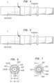
- connection (1) including a first layer (2), a second layer (3) concentrically disposed about the first layer (2), and a laser-induced seal (4) between portions of the first and second layers (2)(3), whereby the laser-induced seal (4) provides a fluid-tight engagement between the first and second layers (2)(3).
- the term "seal" means something that secures.
- the first and second layers (2)(3) are formed from corresponding first and second materials (5)(6), whereby the first and second materials (5)(6) can be any of a numerous and wide variety of materials which upon exposure to a laser (7), can generate the laser-induced seal (4) between portions of the first and second layers (2)(3).
- the first or second material (5)(6) are a thermoplastic elastomer (TPE), polypropylene (PP), polypropylene (PP) derivatives, polyethylene (PE), polyethylene (PE) derivatives, polyolefin elastomer (POE), polyvinylidene fluoride (PVDF), polycarbonate (PC), acrylonitrile butadiene styrene (ABS).
- the first and second materials (5)(6) can be similar materials or the same material.
- the first and second materials (5)(6) can both be polypropylene (PP), polyethylene (PE), or polyvinylidene fluoride (PVDF).
- the first and second materials (5)(6) can be dissimilar materials or different materials.
- the first and second materials (5)(6) can be: polyolefin elastomer (POE) and polypropylene (PP), respectively; polyolefin elastomer (POE) and polyethylene (PE), respectively; thermoplastic elastomer (TPE) and polypropylene (PP), respectively; or thermoplastic elastomer (TPE) and polyethylene (PE), respectively.
- the second layer (3) is concentrically disposed about the first layer (2) such that a portion of a first layer external surface (8) is adjacent to, directly adjacent to, or in contact with a portion of a second layer internal surface (9). Accordingly, upon exposure to a laser (7), the laser-induced seal (4) can be generated between at least the first layer external surface (8) and the second layer internal surface (9).
- first and second layers (2)(3) are each incorporated into corresponding first and second conduits (10)(11).
- Each of the conduits (10)(11) includes opposing conduit external and internal surfaces (12)(13)(14)(15), whereby each conduit internal surface (14)(15) defines a conduit passageway (16)(17) through which fluid can flow.
- fluid means flowable matter, which can include: a gas, a liquid, or the like, or combinations thereof.
- a conduit wall (18) disposes between the conduit external and internal surfaces (12)(13)(14)(15), whereby the conduit wall (18) can have any of a numerous and wide variety of conduit wall thicknesses (19).
- the conduit wall thickness (19) can be in a range of between about 0.05 millimeters (about 0.002 inches) to about 13 millimeters (about 0.5 inches), although the conduit wall thickness (19) can be lesser or greater depending upon the application.
- first and second conduit passageways (16)(17) together form a fluid flow path (21) through which fluid can flow without egressing from the passageways (16)(17), and particularly without egressing from the portions of the passageways (16)(17) proximate the laser-induced seal (4).
- the laser beam (22) can be focused in any of a numerous and wide variety of locations, typically but not necessarily between a second layer external surface (23) and a first layer internal surface (24). Accordingly, the laser-induced seal (4) can be generated in any of a numerous and wide variety of locations between the second layer external surface (23) and the first layer internal surface (24).
- the laser-induced seal (4) can span a portion of the distance between the second layer external surface (23) and the first layer internal surface (24), for example a portion proximate the first layer external surface (8) and the second layer internal surface (9).
- the laser beam (22) can have any power capable of generating a laser-induced seal (4).
- the laser beam (22) can have power in a range of between about 10 Watts to about 120 Watts, although the power can be lesser or greater depending upon the application.
- the laser beam (22) can have any rate of travel capable of generating a laser-induced seal (4).
- the laser beam (22) can have a rate of travel in a range of between about 0.13 millimeters (about 0.005 inches) per second to about 51 millimeters (about 2 inches) per second, although the rate of travel can be lesser or greater depending upon the application.
- the laser-induced seal (4) generated by the laser beam (22) can have any of a numerous and wide variety of laser-induced seal widths (25), whereby the laser-induced seal width (25) is sufficient to allow the laser-induced seal (4) to provide a fluid-tight engagement between the first and second layers (2)(3).
- the laser-induced seal width (25) can be in a range of between about 0.025 millimeters (about 0.001 inches) to about 6.5 millimeters (about 0.25 inches), although the laser-induced seal width (25) can be lesser or greater depending upon the application.
- the laser-induced seal (4) generated by the laser beam (22) can have any of a numerous and wide variety of laser-induced seal lengths (24), whereby the laser-induced seal length (24) is sufficient to allow the laser-induced seal (4) to provide a fluid-tight engagement between the first and second layers (2)(3).
- the laser-induced seal length (24) can span generally the entirety of the circumference (about 360 degrees) of the concentrically disposed first and second conduits (10)(11). Said another way, the laser-induced seal length (24) can completely surround the concentrically disposed first and second conduits (10)(11).
- the laser-induced seal length (24) can span less than the entirety of the circumference of the concentrically disposed first and second conduits (10)(11). Said another way, the laser-induced seal length (24) can only partially surround the concentrically disposed first and second conduits (10)(11).
- relatively smaller conduits (10)(11) having lesser conduit wall thicknesses (19) and/or lesser conduit passageway diameters (20) require exposure to a laser beam (22) having lesser power and a lesser rate of travel to generate a laser-induced seal (4) which provides a fluid-tight engagement of the conduits (10)(11) in relation to relatively larger conduits (10)(11) having greater conduit wall thicknesses (19) and/or greater conduit passageway diameters (20), which require exposure to a laser beam (22) having greater power and a greater rate of travel.
- relatively smaller conduits (10)(11) having lesser conduit wall thicknesses (19) and/or lesser conduit passageway diameters (20) require lesser laser-induced seal widths (25) to provide a fluid-tight engagement between the first and second layers (2)(3) in relation to relatively larger conduits (10)(11) having greater conduit wall thicknesses (19) and/or greater conduit passageway diameters (20), which require greater laser-induced seal widths (25).
- a laser-induced seal (4) which provides a fluid-tight engagement of conduits (10)(11) each having a conduit wall thicknesses (19) of about 0.002 inches and a conduit passageway diameter (20) of about 0.0073 inches
- a laser beam (22) having a power of about 10 Watts and a rate of travel of about 0.005 inches per second to about 1 inch per second
- the laser-induced seal (4) generated can have a laser-induced seal width (25) of about 0.001 inches to about 0.003 inches.
- a laser-induced seal (4) which provides a fluid-tight engagement of conduits (10)(11) each having a conduit wall thicknesses (19) of about 0.0625 inches and a conduit passageway diameter (20) of about 0.50 inches
- a laser beam (22) having a power of about 60 Watts and a rate of travel of about 0.05 inches per second to about 2 inch per second
- the laser-induced seal (4) generated can have a laser-induced seal width (25) of about 0.005 inches to about 0.1875 inches.
- a laser-induced seal (4) which provides a fluid-tight engagement of conduits (10)(11) each having a conduit wall thicknesses (19) of about 0.25 inches and a conduit passageway diameter (20) of about 4 inches
- a laser beam (22) having a power of about 120 Watts and a rate of travel of about 0.05 inches per second to about 2 inch per second
- the laser-induced seal (4) generated can have a laser-induced seal width (25) of about 0.005 inches to about 0.25 inches.
- the laser beam (22) can function to combine, whether partially or completely, the first and second materials (5)(6) to generate the laser-induced seal (4).
- the laser beam (22) can function to fuse, whether partially or completely, the first and second materials (5)(6) to generate the laser-induced seal (4).
- fuse means to blend or join by or as if by melting together.
- the laser-induced seal (4) can be apparent (or evident), meaning that the laser-induced seal (4) is distinguished from its surroundings, and namely from the second layer external surface (23) or the second conduit external surface (13), via one or more distinguishing properties.
- the laser-induced seal (4) can be identified, for example via visual identification, tactile identification, or via other means of identification, thereby confirming that the laser-induced seal (4) has been generated to provide a fluid-tight engagement between first and second layers (2)(3), such as first and second conduits (10)(11).
- the laser-induced seal (4) can comprise or can be apparent (or evident) as a recess (26) which inwardly extends from the second layer external surface (23) or the second conduit external surface (13), whereby the recess (26) is provided upon generation of the laser-induced seal (4). Accordingly, the recess (26) can be seen or felt by an individual viewing or touching the second conduit external surface (13) proximate the laser-induced seal (4).
- the laser-induced seal (4) can comprise or can be apparent (or evident) as a protrusion (27) which outwardly extends from the second layer external surface (23) or the second conduit external surface (13), whereby the protrusion (27) is provided upon generation of the laser-induced seal (4). Accordingly, the protrusion (27) can be seen or felt by an individual viewing or touching the second conduit external surface (13) proximate the laser-induced seal (4).
- the laser-induced seal (4) can comprise or can be apparent (or evident) as a colored indicium (28) having a color which differs from the color of the second conduit (11), whereby the colored indicium (28) is provided upon generation of the laser-induced seal (4). Accordingly, the colored indicium (28) can be seen by an individual viewing the second conduit external surface (13) proximate the laser-induced seal (4).
- a method of making a connection (1) includes providing a first layer (2); concentrically disposing a second layer (3) about the first layer (2); and generating a laser-induced seal (4) between portions of the first and second layers (2)(3), whereby the laser-induced seal (4) provides a fluid-tight engagement between the first and second layers (2)(3).
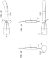
- the laser-induced seal (4) between the first and second layers (2)(3), such as first and second conduits (10)(11), can be generated by rotating concentrically disposed first and second conduits (10)(11) about a rotation axis (29) while a fixed laser beam (22) (meaning a laser beam (22) in a fixed position) is incident upon the portions of the first and second conduits (10)(11) which are to be sealed by the laser-induced seal (4).
- the concentrically disposed first and second conduits (10)(11) can be engaged with a rotatable collet (30). While a fixed laser beam (22) is incident upon the portions of the first and second conduits (10)(11) which are to be sealed by the laser-induced seal (4), the rotatable collet (30) can be rotated to correspondingly rotate the concentrically disposed first and second conduits (10)(11) about the rotation axis (29), thereby generating the laser-induced seal (4) between portions of the first and second conduits (10)(11).
- the robotic arm or the rotatable collet (30) can rotate the concentrically disposed first and second conduits (10)(11) about 360 degrees; following, the laser-induced seal (4) can span generally the entirety or nearly the entirely of the circumference (about 360 degrees) of the concentrically disposed first and second conduits (10)(11); however, the laser-induced seal (4) need not span generally the entirety or nearly the entirely of the circumference of the concentrically disposed first and second conduits (10)(11), depending upon the application.
- the laser-induced seal (4) between the first and second layers (2)(3), such as first and second conduits (10)(11), can be generated by rotating a rotatable laser beam (22) about a rotation axis (29) and about concentrically disposed first and second conduits (10)(11) which are fixedly positioned about the rotation axis (29) such that upon rotation, the rotatable laser beam (22) is incident upon the portions of the first and second conduits (10)(11) which are to be sealed by the laser-induced seal (4).
- the rotatable laser beam (22) can be produced by a rotatable laser (7). Accordingly, upon rotation of the rotatable laser (7) about the rotation axis (29), the laser beam (22) can correspondingly be rotated about concentrically disposed first and second conduits (10)(11) which are fixedly positioned about the rotation axis (29) such that the rotating laser beam (22) is incident upon the portions of the first and second conduits (10)(11) which are to be sealed by the laser-induced seal (4).
- the rotatable laser beam (22) can be rotated about 360 degrees; following, the laser-induced seal (4) can span generally the entirety or nearly the entirely of the circumference (about 360 degrees) of the concentrically disposed first and second conduits (10)(11); however, the laser-induced seal (4) need not span generally the entirety or nearly the entirely of the circumference of the concentrically disposed first and second conduits (10)(11), depending upon the application.
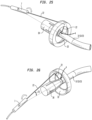
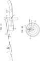
- the laser-induced seal (4) between the first and second layers (2)(3), such as first and second conduits (10)(11), can be generated by rotating a rotatable laser beam (22) about a rotation axis (29), whereby the laser beam (22) is set at an appropriate or desired angle (31) to reflect off of a mirrored surface (32) which facilitates focusing of the laser beam (22) on concentrically disposed first and second conduits (10)(11) which are fixedly positioned about the rotation axis (29) such that the focused laser beam (22) is incident upon the portions of the first and second conduits (10)(11) which are to be sealed by the laser-induced seal (4).
- the mirrored surface (32) can be a concave toroidal mirrored surface (32) which, when the rotatable laser beam (22) is set at an appropriate or desired angle (31) to reflect off of the concave toroidal mirrored surface (32), facilitates focusing of the laser beam (22) on concentrically disposed first and second conduits (10)(11) which are fixedly positioned about the rotation axis (29) such that the focused laser beam (22) is incident upon the portions of the first and second conduits (10)(11) which are to be sealed by the laser-induced seal (4).
- the rotatable laser beam (22) can be rotated about 360 degrees; following, the laser-induced seal (4) can span generally the entirety or nearly the entirely of the circumference (about 360 degrees) of the concentrically disposed first and second conduits (10)(11); however, the laser-induced seal (4) need not span generally the entirety or nearly the entirely of the circumference of the concentrically disposed first and second conduits (10)(11), depending upon the application.
- the laser-induced seal (4) between the first and second layers (2)(3), such as first and second conduits (10)(11), can be generated by a circular laser beam (22) which is set at an appropriate or desired angle (31) to reflect off of a mirrored surface (32) which facilitates focusing of the circular laser beam (22) on concentrically disposed first and second conduits (10)(11) which are fixedly positioned such that the focused laser beam (22) is incident upon the portions of the first and second conduits (10)(11) which are to be sealed by the laser-induced seal (4) (not shown).
- the basic concepts of the present invention may be embodied in a variety of ways.
- the invention involves numerous and varied embodiments of a laser-induced seal of concentrically-layered materials and methods for making and using such a laser-induced seal of concentrically-layered materials, including the best mode.
- each element of an apparatus or each step of a method may be described by an apparatus term or method term. Such terms can be substituted where desired to make explicit the implicitly broad coverage to which this invention is entitled. As but one example, it should be understood that all steps of a method may be disclosed as an action, a means for taking that action, or as an element which causes that action. Similarly, each element of an apparatus may be disclosed as the physical element or the action which that physical element facilitates.
- the term “a” or “an” entity refers to one or more of that entity unless otherwise limited. As such, the terms “a” or “an”, “one or more” and “at least one” can be used interchangeably herein.
Landscapes
- Engineering & Computer Science (AREA)
- Mechanical Engineering (AREA)
- Physics & Mathematics (AREA)
- Optics & Photonics (AREA)
- Health & Medical Sciences (AREA)
- Electromagnetism (AREA)
- Toxicology (AREA)
- General Engineering & Computer Science (AREA)
- Thermal Sciences (AREA)
- Laser Beam Processing (AREA)
- Lining Or Joining Of Plastics Or The Like (AREA)
- Non-Disconnectible Joints And Screw-Threaded Joints (AREA)
- Gasket Seals (AREA)
- Sealing Using Fluids, Sealing Without Contact, And Removal Of Oil (AREA)
- Branch Pipes, Bends, And The Like (AREA)
- Infusion, Injection, And Reservoir Apparatuses (AREA)
Claims (7)
- Verbindung (1), umfassend:eine erste Schicht (2),eine zweite Schicht (3), die konzentrisch um die erste Schicht (2) herum angeordnet ist,wobei die ersten und zweiten Schichten (2, 3) jeweils aus entsprechenden ersten und zweiten Materialien (5, 6) ausgebildet sind, undwobei die ersten und zweiten Materialien (5, 6) aus der Gruppe ausgewählt sind, die aus einem thermoplastischen Elastomer, Polypropylen, Polypropylenderivaten, Polyethylen, Polyethylenderivaten, einem Polyolefinelastomer, Polyvinylidenfluorid, Polycarbonat und Acrylonitril-Butadien-Styrol besteht, undeine laserinduzierte Dichtung (4) zwischen Teilen der ersten und zweiten Schichten (2, 3),wobei die laserinduzierte Dichtung (4) eine fluiddichte Verbindung zwischen den ersten und zweiten Schichten (2, 3) vorsieht, dadurch gekennzeichnet, dass die konzentrische Anordnung der zweiten Schicht (3) um die erste Schicht (2) herum einen Teil einer Erste-Schicht-Außenfläche (8) der ersten Schicht (2) in Nachbarschaft zu einem Teil einer Zweite-Schicht-Innenfläche (9) der zweiten Schicht (3) positioniert,wobei die laserinduzierte Dichtung (4) von einer Zweite-Schicht-Außenfläche (23) der zweiten Schicht (3) unterscheidbar ist,wobei die laserinduzierte Dichtung (4) wenigstens eines der Folgenden aufweist:eine Vertiefung (26), die sich von der Zweite-Schicht-Außenfläche (23) nach innen erstreckt,einen Vorsprung (27), der sich von der Zweite-Schicht-Außenfläche (23) nach außen erstreckt, odereine farbige laserinduzierte Dichtung (4), die eine andere Farbe aufweist als die Farbe der Zweite-Schicht-Außenfläche (23), undwobei die erste Schicht (2) in einem ersten Rohr (10) integriert ist und die zweite Schicht (3) in einem zweiten Rohr (11) integriert ist.
- Verbindung (1) nach Anspruch 1, wobei die Erste-Schicht-Außenfläche (8) die Zweite-Schicht-Innenfläche (9) kontaktiert.
- Verbindung (1) nach Anspruch 2, wobei die laserinduzierte Dichtung (4) wenigstens zwischen der Erste-Schicht-Außenfläche (8) und der Zweite-Schicht-Innenfläche (9) erzeugt wird.
- Verbindung (1) nach Anspruch 1, wobei die laserinduzierte Dichtung (4) eine Laserinduzierte-Dichtung-Länge, die sich über den gesamten Umfang der konzentrisch angeordneten ersten und zweiten Rohre (10, 11) erstreckt, aufweist oder wobei die laserinduzierte Dichtung (4) eine Laserinduzierte-Dichtung-Länge, die sich über weniger als den gesamten Umfang der konzentrisch angeordneten ersten und zweiten Rohre (10, 11) erstreckt, aufweist.
- Verbindung (1) nach Anspruch 1, wobei die ersten und zweiten Materialien kombiniert werden, um die laserinduzierte Dichtung (4) zu erzeugen.
- Verbindung (1) nach Anspruch 5, wobei die ersten und zweiten Materialien (5, 6) verschmolzen werden, um die laserinduzierte Dichtung (4) zu erzeugen.
- Verfahren zum Herstellen einer Verbindung (1) gemäß einem der vorstehenden Ansprüche, umfassend:Vorsehen einer ersten Schicht (2),konzentrisches Anordnen einer zweiten Schicht (3) um die erste Schicht (2) herum,wobei die ersten und zweiten Schichten (2, 3) aus entsprechenden ersten und zweiten Materialien (5, 6) ausgebildet sind, undwobei die ersten und zweiten Materialien (5, 6) aus der Gruppe ausgewählt sind, die aus einem thermoplastischen Elastomer, Polypropylen, Polypropylenderivaten, Polyethylen, Polyethylenderivaten, einem Polyolefinelastomer, Polyvinylidenfluorid, Polycarbonat und Acrylonitril-Butadien-Styrol besteht, undErzeugen einer laserinduzierten Dichtung (4) zwischen Teilen der ersten und zweiten Schichten (2, 3),wobei die laserinduzierte Dichtung (4) eine fluiddichte Verbindung zwischen den ersten und zweiten Schichten (2, 3) vorsieht,konzentrisches Anordnen der zweiten Schicht (3) um die erste Schicht (2) herum, um einen Teil einer Erste-Schicht-Außenfläche (8) der ersten Schicht (2) in Nachbarschaft zu einem Teil einer Zweite-Schicht-Innenfläche (9) der zweiten Schicht (3) zu positionieren,Konfigurieren der laserinduzierten Dichtung (4) als von einer Zweite-Schicht-Außenfläche (23) der zweiten Schicht (3) unterscheidbar,weiterhin Konfigurieren der laserinduzierten Dichtung (4) als einer Vertiefung (26), die sich von der Zweite-Schicht-Außenfläche (23) nach innen erstreckt, und/oderweiterhin Konfigurieren der laserinduzierten Dichtung (4) als eines Vorsprungs (27), der sich von der Zweite-Schicht-Außenfläche (23) nach außen erstreckt, und/oderweiterhin Konfigurieren der laserinduzierten Dichtung (4) mit einer anderen Farbe als der Farbe der Zweite-Schicht-Außenfläche (23),wobei die erste Schicht (2) in einem ersten Rohr (10) integriert ist und die zweite Schicht (3) in einem zweiten Rohr (11) integriert ist.
Applications Claiming Priority (3)
| Application Number | Priority Date | Filing Date | Title |
|---|---|---|---|
| US201562267205P | 2015-12-14 | 2015-12-14 | |
| US15/376,390 US10794523B2 (en) | 2015-12-14 | 2016-12-12 | Laser induced sealing of concentrically layered materials |
| PCT/US2016/066356 WO2017106174A1 (en) | 2015-12-14 | 2016-12-13 | Laser induced sealing of concentrically layered materials |
Publications (4)
| Publication Number | Publication Date |
|---|---|
| EP3390879A1 EP3390879A1 (de) | 2018-10-24 |
| EP3390879A4 EP3390879A4 (de) | 2019-08-07 |
| EP3390879C0 EP3390879C0 (de) | 2025-05-28 |
| EP3390879B1 true EP3390879B1 (de) | 2025-05-28 |
Family
ID=59020097
Family Applications (1)
| Application Number | Title | Priority Date | Filing Date |
|---|---|---|---|
| EP16876481.9A Active EP3390879B1 (de) | 2015-12-14 | 2016-12-13 | Laserinduzierte versiegelung von konzentrisch geschichteten materialien |
Country Status (7)
| Country | Link |
|---|---|
| US (3) | US10794523B2 (de) |
| EP (1) | EP3390879B1 (de) |
| JP (2) | JP7263009B2 (de) |
| KR (1) | KR102508003B1 (de) |
| AU (1) | AU2016370468B2 (de) |
| CA (1) | CA3040663C (de) |
| WO (1) | WO2017106174A1 (de) |
Families Citing this family (4)
| Publication number | Priority date | Publication date | Assignee | Title |
|---|---|---|---|---|
| US10794523B2 (en) | 2015-12-14 | 2020-10-06 | Wilmarc Holdings, Llc | Laser induced sealing of concentrically layered materials |
| DE202020100325U1 (de) * | 2020-01-22 | 2020-02-04 | TI Automotive (Fuldabrück) GmbH | Hitzebeständige, mehrschichtige Fluidleitung |
| DE102021200551A1 (de) * | 2021-01-21 | 2022-07-21 | LPKF WeldingQuipment GmbH | Verfahren und Vorrichtung zum Laserschweißen zweier thermoplastischer Bauteile |
| IT202100031232A1 (it) * | 2021-12-14 | 2023-06-14 | Hutchinson S R L | Connessione per fluido con due saldature |
Citations (3)
| Publication number | Priority date | Publication date | Assignee | Title |
|---|---|---|---|---|
| JP2004090628A (ja) * | 2002-07-09 | 2004-03-25 | Ube Ind Ltd | パイプ形状品の接合方法 |
| US20100096388A1 (en) * | 2007-02-23 | 2010-04-22 | Toyo Seikan Kaisha, Ltd | Method of melt-adhering a member having a layer of a thermoplastic resin and thermoplastic resin container with lid |
| US20140035279A1 (en) * | 2012-08-03 | 2014-02-06 | Lincoln Global, Inc. | Methods and systems of joining pipes |
Family Cites Families (49)
| Publication number | Priority date | Publication date | Assignee | Title |
|---|---|---|---|---|
| US2345037A (en) * | 1942-10-20 | 1944-03-28 | Bell Aircraft Corp | Spot welding method |
| US2763057A (en) * | 1954-07-12 | 1956-09-18 | Koldweld Corp | Cold pressure welding of metal foil |
| US3429591A (en) * | 1967-09-06 | 1969-02-25 | Caterpillar Tractor Co | Precombustion chambers |
| US3473833A (en) * | 1967-12-28 | 1969-10-21 | Nat Distillers Chem Corp | Plastic pipe coupling |
| JPS60225737A (ja) * | 1984-04-25 | 1985-11-11 | Toyota Motor Corp | 異種合成樹脂材料の接合方法 |
| JPH0435670Y2 (de) | 1985-05-30 | 1992-08-24 | ||
| US5259894A (en) * | 1990-01-26 | 1993-11-09 | Sampson Richard K | Method for solvent bonding non-porous materials to automatically create variable bond characteristics |
| US5267959A (en) * | 1991-11-29 | 1993-12-07 | Schneider, Inc. | Laser bonding of angioplasty balloon catheters |
| JP3369000B2 (ja) | 1994-08-17 | 2003-01-20 | 三井化学株式会社 | パイプの接続方法 |
| US5593605A (en) * | 1994-10-11 | 1997-01-14 | Crc-Evans Pipeline International, Inc. | Internal laser welder for pipeline |
| JPH0911332A (ja) | 1995-07-04 | 1997-01-14 | Mitsui Toatsu Chem Inc | パイプの接続方法 |
| US20020100540A1 (en) * | 1998-07-10 | 2002-08-01 | Alexander Savitski | Simultaneous butt and lap joints |
| JP3799599B2 (ja) * | 2001-02-26 | 2006-07-19 | 株式会社デンソー | 溶接装置および溶接方法 |
| US6764710B2 (en) | 2001-07-18 | 2004-07-20 | Scimed Life Systems, Inc. | Light emitting markers for use with substrates |
| JP4747464B2 (ja) * | 2001-08-27 | 2011-08-17 | 株式会社デンソー | スパークプラグおよびその製造方法 |
| US6913056B2 (en) * | 2002-01-31 | 2005-07-05 | Baxter International Inc. | Apparatus and method for connecting and disconnecting flexible tubing |
| EP1552916A1 (de) * | 2002-07-09 | 2005-07-13 | Ube Industries, Ltd. | Verfahren zur verbindung von rohrförmigen objekten |
| JP4113752B2 (ja) | 2002-09-25 | 2008-07-09 | 株式会社ファインディバイス | 接合装置 |
| DE10245355A1 (de) * | 2002-09-27 | 2004-04-08 | Degussa Ag | Rohrverbindung |
| EP1477264A1 (de) * | 2003-05-16 | 2004-11-17 | Lasag Ag | Vorrichtung zum Erzeugen eines drehenden Laserstrahls |
| US6832785B1 (en) * | 2003-07-21 | 2004-12-21 | Itt Manufacturing Enterprises, Inc. | Spin welded fluid coupling |
| DE60305912T2 (de) * | 2003-08-05 | 2007-02-01 | Lasag Ag | Verfahren zur Herstellung einer medizinischen Nadel |
| US6902208B1 (en) * | 2003-12-10 | 2005-06-07 | Dayco Product, Llc | Gas impermeable tube joint and method of forming same |
| ES2526193T3 (es) * | 2003-12-26 | 2015-01-08 | Kuraray Co., Ltd. | Procedimiento para la fabricación de un artículo tubular |
| JP4492784B2 (ja) | 2004-01-19 | 2010-06-30 | 株式会社デンソー | レーザ溶着部材の製造方法 |
| JP2005305985A (ja) | 2004-03-22 | 2005-11-04 | Fine Device:Kk | 管材の接合方法、管材とサドルの接合方法及びレーザ接合装置 |
| US7505504B2 (en) * | 2004-10-07 | 2009-03-17 | Sango Co., Ltd. | Laser processing device |
| US20080187697A1 (en) * | 2005-03-08 | 2008-08-07 | Masaaki Amano | Structure and Method for Bonding Two Members, Gas Container and Method for Manufacturing Such Gas Container |
| US8114113B2 (en) * | 2005-09-23 | 2012-02-14 | Acclarent, Inc. | Multi-conduit balloon catheter |
| US20070222213A1 (en) * | 2006-03-24 | 2007-09-27 | Florencia Andersen | Thermoplastic element for protection against corrosion in the thermofusion coupling of a thermoplastic tube |
| DE102006040650A1 (de) * | 2006-08-30 | 2008-03-13 | Robert Bosch Gmbh | Verfahren zum Fügen von Bauteilen mit geschlossenem Hohlquerschnitt |
| DE102007035717A1 (de) * | 2006-12-27 | 2008-07-03 | Robert Bosch Gmbh | Laserstrahlschweißvorrichtung sowie Laserstrahlschweißverfahren |
| US7829819B2 (en) * | 2007-02-08 | 2010-11-09 | Automotive Components Holdings, Llc | Attaching a component to an internal surface of a tank formed of polymer |
| WO2008138709A2 (de) * | 2007-05-11 | 2008-11-20 | Voss Automotive Gmbh | Verbindungsvorrichtung für strömungsmedien |
| JP2009056722A (ja) | 2007-08-31 | 2009-03-19 | Canon Inc | レーザ溶着ユニット及びレーザ溶着方法 |
| JP2009083406A (ja) * | 2007-10-02 | 2009-04-23 | Kawano:Kk | パイプの接合方法 |
| US7934701B2 (en) * | 2008-07-01 | 2011-05-03 | Kay Ronald J | Safety handrail apparatus and manufacturing methods |
| JP5248344B2 (ja) * | 2009-01-20 | 2013-07-31 | 本田技研工業株式会社 | レーザ溶接方法 |
| US8038178B2 (en) * | 2009-03-31 | 2011-10-18 | Hitachi, Ltd | High pressure fuel pipe construction for an internal combustion engine |
| EP2243501A1 (de) * | 2009-04-24 | 2010-10-27 | Eurocor Gmbh | Schellack- und paclitaxel-beschichtete Katheterballons |
| US9283151B2 (en) * | 2009-10-23 | 2016-03-15 | Louis O. Porreca, JR. | Enteral feeding tube having unclogging lumen |
| WO2011109039A1 (en) * | 2010-03-04 | 2011-09-09 | Aaren Scientific Inc. | System for forming and modifying lenses and lenses formed thereby |
| WO2013065370A1 (ja) * | 2011-11-02 | 2013-05-10 | テルモ株式会社 | 針付き外筒の製造方法及び針付き外筒 |
| JP2014147962A (ja) * | 2013-02-01 | 2014-08-21 | Olympus Medical Systems Corp | 部材接合方法、部材接合構造、および継手管 |
| DE202014100268U1 (de) * | 2014-01-23 | 2015-04-27 | Rehau Ag + Co | Medienleitung |
| US20150330541A1 (en) * | 2014-05-15 | 2015-11-19 | Ayrlett Llc | Process of making a plumbing fitting, and the product thereof |
| US9776278B2 (en) * | 2015-07-29 | 2017-10-03 | Abbott Cardiovascular Systems, Inc. | Laser welder alignment system |
| FR3041280B1 (fr) * | 2015-09-23 | 2018-03-23 | Saipem S.A. | Methode d'assemblage de tubes par soudage laser |
| US10794523B2 (en) | 2015-12-14 | 2020-10-06 | Wilmarc Holdings, Llc | Laser induced sealing of concentrically layered materials |
-
2016
- 2016-12-12 US US15/376,390 patent/US10794523B2/en active Active
- 2016-12-13 EP EP16876481.9A patent/EP3390879B1/de active Active
- 2016-12-13 JP JP2018549417A patent/JP7263009B2/ja active Active
- 2016-12-13 KR KR1020187019764A patent/KR102508003B1/ko active Active
- 2016-12-13 CA CA3040663A patent/CA3040663C/en active Active
- 2016-12-13 WO PCT/US2016/066356 patent/WO2017106174A1/en not_active Ceased
- 2016-12-13 AU AU2016370468A patent/AU2016370468B2/en active Active
-
2020
- 2020-07-31 US US16/945,036 patent/US11608926B2/en active Active
-
2022
- 2022-02-28 JP JP2022029477A patent/JP2022079462A/ja active Pending
-
2023
- 2023-03-21 US US18/124,148 patent/US20230220939A1/en not_active Abandoned
Patent Citations (3)
| Publication number | Priority date | Publication date | Assignee | Title |
|---|---|---|---|---|
| JP2004090628A (ja) * | 2002-07-09 | 2004-03-25 | Ube Ind Ltd | パイプ形状品の接合方法 |
| US20100096388A1 (en) * | 2007-02-23 | 2010-04-22 | Toyo Seikan Kaisha, Ltd | Method of melt-adhering a member having a layer of a thermoplastic resin and thermoplastic resin container with lid |
| US20140035279A1 (en) * | 2012-08-03 | 2014-02-06 | Lincoln Global, Inc. | Methods and systems of joining pipes |
Also Published As
| Publication number | Publication date |
|---|---|
| US20170167653A1 (en) | 2017-06-15 |
| EP3390879C0 (de) | 2025-05-28 |
| AU2016370468B2 (en) | 2022-02-10 |
| CA3040663C (en) | 2022-05-17 |
| AU2016370468A1 (en) | 2018-07-05 |
| JP2022079462A (ja) | 2022-05-26 |
| KR102508003B1 (ko) | 2023-03-08 |
| EP3390879A1 (de) | 2018-10-24 |
| KR20180094030A (ko) | 2018-08-22 |
| US20200363002A1 (en) | 2020-11-19 |
| US10794523B2 (en) | 2020-10-06 |
| US20230220939A1 (en) | 2023-07-13 |
| JP2019502078A (ja) | 2019-01-24 |
| US11608926B2 (en) | 2023-03-21 |
| EP3390879A4 (de) | 2019-08-07 |
| JP7263009B2 (ja) | 2023-04-24 |
| CA3040663A1 (en) | 2017-06-22 |
| WO2017106174A1 (en) | 2017-06-22 |
Similar Documents
| Publication | Publication Date | Title |
|---|---|---|
| CN102765194B (zh) | 用于连接成形塑料体的激光透射焊接方法 | |
| US6596122B1 (en) | Simultaneous butt and lap joints | |
| US20020100540A1 (en) | Simultaneous butt and lap joints | |
| DE19916786C2 (de) | Verfahren zur Verbindung mindestens zweier aus Kunststoff bestehender Rohr- und/oder Wandelemente | |
| JP2012500120A (ja) | レーザヘッド及びレーザ照射による管状部品の接合方法 | |
| US20230220939A1 (en) | Laser Induced Sealing of Concentrically Layered Materials | |
| CN104520057A (zh) | 部件接合方法、部件接合构造和接头管 | |
| KR20170116249A (ko) | 용착 방법 및 용착체 | |
| JP6542447B1 (ja) | 樹脂パイプと樹脂部材との接合方法および接合構造 | |
| US20050251986A1 (en) | Method of joining pipe-shaped articles | |
| JP4113752B2 (ja) | 接合装置 | |
| WO2014024033A1 (en) | Method of forming a pipe joint and pipe joint | |
| JP4949708B2 (ja) | 樹脂部材の接合方法 | |
| JP2004100765A (ja) | ホース溶着接続構造 | |
| JP6311511B2 (ja) | ガラス接合体の製造方法 | |
| JP2005288947A (ja) | 接合方法、接合部材及び部品 | |
| JP4492784B2 (ja) | レーザ溶着部材の製造方法 | |
| JP4911401B2 (ja) | 2重壁を有するプラスチック成形品および溶着接合方法 | |
| CN109421281B (zh) | 非透射性复合材料的激光焊接方法 | |
| JPS61192543A (ja) | チユ−ブ容器の製造方法 | |
| JPH10166452A (ja) | 赤外線によるプラスチックの融着方法および赤外線吸収体 | |
| KR100417032B1 (ko) | 수지파이프의 접합방법 | |
| Mueller et al. | Optimizing weld joint design for bond strength and functional properties in laser welding of polymers |
Legal Events
| Date | Code | Title | Description |
|---|---|---|---|
| STAA | Information on the status of an ep patent application or granted ep patent |
Free format text: STATUS: THE INTERNATIONAL PUBLICATION HAS BEEN MADE |
|
| PUAI | Public reference made under article 153(3) epc to a published international application that has entered the european phase |
Free format text: ORIGINAL CODE: 0009012 |
|
| STAA | Information on the status of an ep patent application or granted ep patent |
Free format text: STATUS: REQUEST FOR EXAMINATION WAS MADE |
|
| 17P | Request for examination filed |
Effective date: 20180705 |
|
| AK | Designated contracting states |
Kind code of ref document: A1 Designated state(s): AL AT BE BG CH CY CZ DE DK EE ES FI FR GB GR HR HU IE IS IT LI LT LU LV MC MK MT NL NO PL PT RO RS SE SI SK SM TR |
|
| AX | Request for extension of the european patent |
Extension state: BA ME |
|
| DAV | Request for validation of the european patent (deleted) | ||
| DAX | Request for extension of the european patent (deleted) | ||
| A4 | Supplementary search report drawn up and despatched |
Effective date: 20190708 |
|
| RIC1 | Information provided on ipc code assigned before grant |
Ipc: B29C 65/16 20060101AFI20190702BHEP Ipc: F16L 37/00 20060101ALI20190702BHEP Ipc: F16L 37/244 20060101ALI20190702BHEP Ipc: F16L 47/02 20060101ALI20190702BHEP Ipc: F16L 13/02 20060101ALI20190702BHEP |
|
| STAA | Information on the status of an ep patent application or granted ep patent |
Free format text: STATUS: EXAMINATION IS IN PROGRESS |
|
| 17Q | First examination report despatched |
Effective date: 20210623 |
|
| REG | Reference to a national code |
Ref country code: DE Free format text: PREVIOUS MAIN CLASS: F16L0013020000 Ipc: B29C0065160000 Ref legal event code: R079 Ref document number: 602016092411 Country of ref document: DE |
|
| GRAP | Despatch of communication of intention to grant a patent |
Free format text: ORIGINAL CODE: EPIDOSNIGR1 |
|
| STAA | Information on the status of an ep patent application or granted ep patent |
Free format text: STATUS: GRANT OF PATENT IS INTENDED |
|
| RIC1 | Information provided on ipc code assigned before grant |
Ipc: F16L 47/02 20060101ALI20241210BHEP Ipc: B29C 65/16 20060101AFI20241210BHEP |
|
| INTG | Intention to grant announced |
Effective date: 20241219 |
|
| GRAS | Grant fee paid |
Free format text: ORIGINAL CODE: EPIDOSNIGR3 |
|
| GRAA | (expected) grant |
Free format text: ORIGINAL CODE: 0009210 |
|
| STAA | Information on the status of an ep patent application or granted ep patent |
Free format text: STATUS: THE PATENT HAS BEEN GRANTED |
|
| AK | Designated contracting states |
Kind code of ref document: B1 Designated state(s): AL AT BE BG CH CY CZ DE DK EE ES FI FR GB GR HR HU IE IS IT LI LT LU LV MC MK MT NL NO PL PT RO RS SE SI SK SM TR |
|
| REG | Reference to a national code |
Ref country code: GB Ref legal event code: FG4D |
|
| REG | Reference to a national code |
Ref country code: CH Ref legal event code: EP |
|
| REG | Reference to a national code |
Ref country code: IE Ref legal event code: FG4D Ref country code: DE Ref legal event code: R096 Ref document number: 602016092411 Country of ref document: DE |
|
| U01 | Request for unitary effect filed |
Effective date: 20250630 |
|
| U07 | Unitary effect registered |
Designated state(s): AT BE BG DE DK EE FI FR IT LT LU LV MT NL PT RO SE SI Effective date: 20250704 |
|
| PG25 | Lapsed in a contracting state [announced via postgrant information from national office to epo] |
Ref country code: ES Free format text: LAPSE BECAUSE OF FAILURE TO SUBMIT A TRANSLATION OF THE DESCRIPTION OR TO PAY THE FEE WITHIN THE PRESCRIBED TIME-LIMIT Effective date: 20250528 |
|
| PG25 | Lapsed in a contracting state [announced via postgrant information from national office to epo] |
Ref country code: GR Free format text: LAPSE BECAUSE OF FAILURE TO SUBMIT A TRANSLATION OF THE DESCRIPTION OR TO PAY THE FEE WITHIN THE PRESCRIBED TIME-LIMIT Effective date: 20250829 Ref country code: NO Free format text: LAPSE BECAUSE OF FAILURE TO SUBMIT A TRANSLATION OF THE DESCRIPTION OR TO PAY THE FEE WITHIN THE PRESCRIBED TIME-LIMIT Effective date: 20250828 |
|
| PG25 | Lapsed in a contracting state [announced via postgrant information from national office to epo] |
Ref country code: PL Free format text: LAPSE BECAUSE OF FAILURE TO SUBMIT A TRANSLATION OF THE DESCRIPTION OR TO PAY THE FEE WITHIN THE PRESCRIBED TIME-LIMIT Effective date: 20250528 |
|
| PG25 | Lapsed in a contracting state [announced via postgrant information from national office to epo] |
Ref country code: HR Free format text: LAPSE BECAUSE OF FAILURE TO SUBMIT A TRANSLATION OF THE DESCRIPTION OR TO PAY THE FEE WITHIN THE PRESCRIBED TIME-LIMIT Effective date: 20250528 |
|
| PG25 | Lapsed in a contracting state [announced via postgrant information from national office to epo] |
Ref country code: RS Free format text: LAPSE BECAUSE OF FAILURE TO SUBMIT A TRANSLATION OF THE DESCRIPTION OR TO PAY THE FEE WITHIN THE PRESCRIBED TIME-LIMIT Effective date: 20250828 |
|
| PG25 | Lapsed in a contracting state [announced via postgrant information from national office to epo] |
Ref country code: IS Free format text: LAPSE BECAUSE OF FAILURE TO SUBMIT A TRANSLATION OF THE DESCRIPTION OR TO PAY THE FEE WITHIN THE PRESCRIBED TIME-LIMIT Effective date: 20250928 |
|
| PGFP | Annual fee paid to national office [announced via postgrant information from national office to epo] |
Ref country code: GB Payment date: 20251218 Year of fee payment: 10 |
|
| PG25 | Lapsed in a contracting state [announced via postgrant information from national office to epo] |
Ref country code: SM Free format text: LAPSE BECAUSE OF FAILURE TO SUBMIT A TRANSLATION OF THE DESCRIPTION OR TO PAY THE FEE WITHIN THE PRESCRIBED TIME-LIMIT Effective date: 20250528 |
|
| PG25 | Lapsed in a contracting state [announced via postgrant information from national office to epo] |
Ref country code: CZ Free format text: LAPSE BECAUSE OF FAILURE TO SUBMIT A TRANSLATION OF THE DESCRIPTION OR TO PAY THE FEE WITHIN THE PRESCRIBED TIME-LIMIT Effective date: 20250528 |
|
| PG25 | Lapsed in a contracting state [announced via postgrant information from national office to epo] |
Ref country code: SK Free format text: LAPSE BECAUSE OF FAILURE TO SUBMIT A TRANSLATION OF THE DESCRIPTION OR TO PAY THE FEE WITHIN THE PRESCRIBED TIME-LIMIT Effective date: 20250528 |
|
| U20 | Renewal fee for the european patent with unitary effect paid |
Year of fee payment: 10 Effective date: 20251222 |
|
| PLBE | No opposition filed within time limit |
Free format text: ORIGINAL CODE: 0009261 |
|
| STAA | Information on the status of an ep patent application or granted ep patent |
Free format text: STATUS: NO OPPOSITION FILED WITHIN TIME LIMIT |
|
| REG | Reference to a national code |
Ref country code: CH Ref legal event code: L10 Free format text: ST27 STATUS EVENT CODE: U-0-0-L10-L00 (AS PROVIDED BY THE NATIONAL OFFICE) Effective date: 20260409 |
|
| 26N | No opposition filed |
Effective date: 20260303 |