EP3387205B1 - Isolierbefestigungsprofil und verfahren zur herstellung eines isolierbefestigungsprofils - Google Patents
Isolierbefestigungsprofil und verfahren zur herstellung eines isolierbefestigungsprofils Download PDFInfo
- Publication number
- EP3387205B1 EP3387205B1 EP16823060.5A EP16823060A EP3387205B1 EP 3387205 B1 EP3387205 B1 EP 3387205B1 EP 16823060 A EP16823060 A EP 16823060A EP 3387205 B1 EP3387205 B1 EP 3387205B1
- Authority
- EP
- European Patent Office
- Prior art keywords
- mounting profile
- insulating mounting
- polymer
- profile
- resin
- Prior art date
- Legal status (The legal status is an assumption and is not a legal conclusion. Google has not performed a legal analysis and makes no representation as to the accuracy of the status listed.)
- Active
Links
Images


Classifications
-
- E—FIXED CONSTRUCTIONS
- E06—DOORS, WINDOWS, SHUTTERS, OR ROLLER BLINDS IN GENERAL; LADDERS
- E06B—FIXED OR MOVABLE CLOSURES FOR OPENINGS IN BUILDINGS, VEHICLES, FENCES OR LIKE ENCLOSURES IN GENERAL, e.g. DOORS, WINDOWS, BLINDS, GATES
- E06B1/00—Border constructions of openings in walls, floors, or ceilings; Frames to be rigidly mounted in such openings
- E06B1/56—Fastening frames to the border of openings or to similar contiguous frames
- E06B1/60—Fastening frames to the border of openings or to similar contiguous frames by mechanical means, e.g. anchoring means
- E06B1/6015—Anchoring means
- E06B1/6038—Anchoring means specially adapted for being embedded in the wall
-
- E—FIXED CONSTRUCTIONS
- E06—DOORS, WINDOWS, SHUTTERS, OR ROLLER BLINDS IN GENERAL; LADDERS
- E06B—FIXED OR MOVABLE CLOSURES FOR OPENINGS IN BUILDINGS, VEHICLES, FENCES OR LIKE ENCLOSURES IN GENERAL, e.g. DOORS, WINDOWS, BLINDS, GATES
- E06B1/00—Border constructions of openings in walls, floors, or ceilings; Frames to be rigidly mounted in such openings
- E06B1/56—Fastening frames to the border of openings or to similar contiguous frames
- E06B1/60—Fastening frames to the border of openings or to similar contiguous frames by mechanical means, e.g. anchoring means
- E06B1/6015—Anchoring means
-
- E—FIXED CONSTRUCTIONS
- E06—DOORS, WINDOWS, SHUTTERS, OR ROLLER BLINDS IN GENERAL; LADDERS
- E06B—FIXED OR MOVABLE CLOSURES FOR OPENINGS IN BUILDINGS, VEHICLES, FENCES OR LIKE ENCLOSURES IN GENERAL, e.g. DOORS, WINDOWS, BLINDS, GATES
- E06B1/00—Border constructions of openings in walls, floors, or ceilings; Frames to be rigidly mounted in such openings
- E06B1/003—Cavity wall closers; Fastening door or window frames in cavity walls
-
- E—FIXED CONSTRUCTIONS
- E06—DOORS, WINDOWS, SHUTTERS, OR ROLLER BLINDS IN GENERAL; LADDERS
- E06B—FIXED OR MOVABLE CLOSURES FOR OPENINGS IN BUILDINGS, VEHICLES, FENCES OR LIKE ENCLOSURES IN GENERAL, e.g. DOORS, WINDOWS, BLINDS, GATES
- E06B1/00—Border constructions of openings in walls, floors, or ceilings; Frames to be rigidly mounted in such openings
- E06B1/02—Base frames, i.e. template frames for openings in walls or the like, provided with means for securing a further rigidly-mounted frame; Special adaptations of frames to be fixed therein
-
- E—FIXED CONSTRUCTIONS
- E06—DOORS, WINDOWS, SHUTTERS, OR ROLLER BLINDS IN GENERAL; LADDERS
- E06B—FIXED OR MOVABLE CLOSURES FOR OPENINGS IN BUILDINGS, VEHICLES, FENCES OR LIKE ENCLOSURES IN GENERAL, e.g. DOORS, WINDOWS, BLINDS, GATES
- E06B1/00—Border constructions of openings in walls, floors, or ceilings; Frames to be rigidly mounted in such openings
- E06B1/70—Sills; Thresholds
- E06B2001/707—Thresholds with special provision for insulation
-
- E—FIXED CONSTRUCTIONS
- E06—DOORS, WINDOWS, SHUTTERS, OR ROLLER BLINDS IN GENERAL; LADDERS
- E06B—FIXED OR MOVABLE CLOSURES FOR OPENINGS IN BUILDINGS, VEHICLES, FENCES OR LIKE ENCLOSURES IN GENERAL, e.g. DOORS, WINDOWS, BLINDS, GATES
- E06B3/00—Window sashes, door leaves, or like elements for closing wall or like openings; Layout of fixed or moving closures, e.g. windows in wall or like openings; Features of rigidly-mounted outer frames relating to the mounting of wing frames
- E06B3/04—Wing frames not characterised by the manner of movement
- E06B3/06—Single frames
- E06B3/08—Constructions depending on the use of specified materials
- E06B3/20—Constructions depending on the use of specified materials of plastics
- E06B3/205—Constructions depending on the use of specified materials of plastics moulded or extruded around a core
Definitions
- the subject matter of the invention is an insulation mounting profile, which is designed to create fastening systems and thermal insulation of windows and doors. It is usually placed in the insulation area of all kinds of buildings, including multi- family buildings, single-family buildings, as well as public buildings, livestock buildings and farm buildings.
- the subject matter of the invention is also a method for manufacturing of unified insulation mounting profiles, which can easily be used for manufacturing of individualized insulation mounting profiles, tailored to individual needs of investors.
- the method involves placing the thermal insulation element in the location of the horizontal contact between the window and the wall, which is also the external sill.
- the thermal insulation element is made of a thermal insulation material in the form of a narrow board, having a trapezoidal shape in the cross section. On the surface of the thermal insulation material of the element is placed a thin layer of plastic with a mesh.
- the wall has through fixing hollows, and the window with the element is fixed to the window opening by a screw element.
- the angular element of the thermal insulation housing comprises a base and a side wall, made of a thermal insulation board, where between two stiffening linings is placed a layer of the thermal insulation material.
- the base and the side wall are connected to each other to form the angular bent edge at the connection point.
- the angular element has on the opposite face edges the longitudinal seal protrusions on the one side, and the longitudinal seal socket on the other.
- the reinforcing steel profile with the thermal insert for manufacturing of windows and doors of PVC profiles, constituting a steal upper and side element, separated by a rolled thermal insert, is characterized by the fact that the upper element has a bend forming the protrusion and the socket made between the double and single bend of the protrusion, where is placed the thermal insert by one end, located in the socket of the side element by the other end, formed between the double and single bend of the protrusion, wherein the vertical arm of the side element has a protrusion.
- WO2015/043719 discloses an insulating mounting profile for mounting and supporting window or door frames according to the preamble of claim 1.
- the purpose of the invention is to develop such a mounting profile, which will enable the creation of the entire fastening system and the thermal insulation of windows, doors and glass facades, as well as enable and at least facilitate their assembly, regardless of the shape and regardless of the type of the wall, in which are made the holes built using the developed profile.
- the purpose of the invention is also to develop an efficient method for manufacturing of the insulating mounting profile.
- the essence of the insulating mounting profile for mounting and supporting window or door frames lies in the fact that it is an angle brackets made of any material, preferably steel or composite with high density, which can carry loads of up to 450 kg/m2 and which is supplemented by an adhering foam. They constitute an essential part of the insulating mounting profile and are covered with a layer of resin, and then with a layer of fiber and the profile is equipped with anchors.
- the angle bracket has the shape of the letter "L".
- the angle bracket and the foam create a compact, basic part of the profile with the cross-section of a right-angled triangle.
- the foam is made of a foamed polypropylene with a cellular structure; is preferably made up of a linear polymer or a branched polymer or a side-chain polymer or a multi-branched polymer or a star polymer or a ladder polymer or a cross-linked polymer or a cyclic polymer or a catetane polymer or a ratexan polymer or a dendrimeric polymer, and especially a floral sponge, a polystyrene, a styrodur, or a polyurethane with a density from 15 kg/m2 to 450 kg/m2, foamed PVC or other plastics, such as: ABS, PE, PP, or compressed wood chips or other material combined with polyurethane,
- foamed PVC or other plastics such as: ABS, PE, PP, or compressed wood chips or other material combined with polyurethane
- resin is epoxy resin, urea resin or polyurethane.
- the layer of fiber is glass fiber, carbon fiber or resin-impregnated fiber.
- the basic part of the insulating profile is fixed to the supplementing foam, preferably made of one of the materials, from which the adhering foam is made.
- the profile has sockets, which are equipped with plugs.
- the profile is an appropriately shaped profile, forming the window sill, i.e. the sill profile.
- the plugs have two layers - the outer layer of the plug is a membrane, preferably EPDM or Winflex, while the inner layer is an adhesive, and in addition, optionally the plug is protected from sticking with a siliconized paper.
- the method for manufacturing of the insulating mounting profile is defined in claim 11 and it is performed as a result of successively taken steps:
- the developed insulating mounting profile is made of materials that have been used so far in completely different fields, of polymers (including the floral sponge, i.e. of polyurethane with short polymer chains), which in combination with resins exhibit surprising, hitherto unknown properties, perfectly suitable for the use in construction.
- the solution according to the invention allows a simple and quick installation of windows, doors and glass facades eliminating thermal bridges, previously formed at the place of their installation.
- the developed insulating mounting profile can reduce structural components used so far in the installation of windows and doors, because it can be a separate structural component, which alone carries significant loads. This is possible thanks to the materials used, whose properties have not been yet applied in construction at all - or were only used for other purposes. Both, due to the properties of the materials used, as well as due to the characteristics of the profile structure - there was obtained an unexpectedly favorable distribution of stresses in the profile and in the entire beam, which allows to achieve the maximum strength with extremely low expenditure of materials and use of materials, which excellent technical parameters have not been used so far.
- the developed profile is extremely light after coating with glass fiber, or carbon fiber, or after soaking with resin - is extremely tough, and yet exhibits excellent thermal insulation properties.
- the developed structure eliminates the need for placing windows or doors in the wall opening; these elements can be installed outside the wall, so that the thermal insulation is directly fed to the window or the door.
- the solution according to the invention eliminates any thermal bridges, which are created so far when connecting the windows and the doors with the wall face.
- the invention has led to the development of an extremely strong profile, which makes it possible to limit the additional structural elements in the building, because the profile plays their role alone and replaces them.
- the method according to the invention i.e, the method for manufacturing of insulating mounting profiles as defined in claim 11, provides for the organization of a deliberate and extremely easily organized technological cycle that enables both the manufacture of highly customized and even most complex profiles, as well as simple and standardized profiles.
- Fig. 1 - shows an axonometric view of the cross section through two juxtaposed profiles, where in one of them the steel angle bracket is used
- Fig. 2 - shows an axonometric view of the cross section through the profile using the angle bracket made of densified mass
- Fig. 3 - shows an axonometric view of the cross section of the profile using a different angle bracket made of densified mass
- Fig. 4 - shows a horizontal module of the profile
- Fig. 5 - shows a vertical module of the profile with properly positioned plugs
- Fig. 6 - shows a horizontal module of the profile with another installation method, using anchors
- Fig. 1 - shows an axonometric view of the cross section through two juxtaposed profiles, where in one of them the steel angle bracket is used
- Fig. 2 - shows an axonometric view of the cross section through the profile using the angle bracket made of densified mass
- Fig. 3 - shows an a
- FIG. 7 - shows an arched module of the profile
- Fig. 8 - shows an example of the insulation of the round window frame, using circular arc modules of the profile
- Fig. 9 - shows an axonometric view of the cross section through the profile, where in addition the sill profile is used in a shape forming the window sill
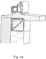
- the drawings Fig. 10 , Fig. 11 Fig. 12 , Fig. 13 and Fig. 14 - show an axonometric view of profiles, with which sill profiles of another type are also juxtaposed
- Fig. 15 - shows the cleaning stage of the cut sill profile from particles of contaminants, which precedes the coating stage of the sill profile made using the method presented in the developed method
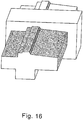
- Fig. 16 - shows the method for coating of the sill profile with resins
- Fig. 17 - shows a device for applying glass fiber or its equivalent to the sill profile
- Fig. 18 - presents an axonometric view of the cross section through the profile, which is covered at the bottom and on the side with a thick layer of the insulation material.
- an essential structural element of the developed insulating mounting profile is the angle bracket 1, with the shape of the letter "L”, made of any material, preferably steel or composite with a high density, that can carry loads even up to 450 kg/m2.
- the angle bracket 1 supplemented with the adhering foam 2 form a compact, basic part of the profile with the cross section of a right-angled triangle.
- the foam 2 can be made of any plastic, preferably of foamed polypropylene having a cellular structure.
- the foam 2 can be:
- the basic part of the developed insulating mounting profile consisting of the angle bracket 1 with the adhering foam 2, is covered with the layer of resin 4, for example, with epoxy resin, urea resin or polyurethane resin, and the layer of glass fiber 5, carbon fiber or fiber impregnated with resin.
- the layer of resin 4 for example, with epoxy resin, urea resin or polyurethane resin, and the layer of glass fiber 5, carbon fiber or fiber impregnated with resin.
- the supplementing foam 3 made, for example, of one of the materials, of which the adhering foam 2 is made.
- the supplementing foam 3, along with the previously prepared basic part of the profile is covered with the layer of resin 4, and then with the layer of fiber 5.
- Resin 4 may be then tainted in any color.
- sockets 6 are made in the course of manufacturing of the profile. Sockets 6 are the holes that allow easy insertion of screws, and thus installation of the insulating mounting profile to the wall face.
- Plugs 7 have two layers - the outer layer of the plug 7 is a membrane, preferably EPDM or Winflex, while the outer layer is an adhesive, thanks to which plugs 7 are installed to the insulating mounting profile.
- the outer layer of the plug 7 is a membrane, preferably EPDM or Winflex, while the outer layer is an adhesive, thanks to which plugs 7 are installed to the insulating mounting profile.
- plugs 7 are partially adhered to the profile, while on the other part the plug 7 is protected from adhering with a siliconized paper. Plugs 7 are adhered to the profile in such a way as to leave free access to the slot 6, and hence ensure easy installation of the profile to the wall.
- the adhesive protection which usually comprises a silicone paper, and stick the remainder of the plug 7, and thus protect sockets 6 and installation elements, for example, from the penetration of moisture from the outside.
- the developed insulating mounting profile can be also installed to the wall using anchors 8.
- the developed insulating mounting profile can be formed in any manner (as shown in Figure 4, 5 , 6 and 7 ). This allows the use of the developed profile for easy installation of windows and doors of any shape, according to the user's individual needs. In the course of the installation of windows, any mounting profile can have an appropriately formed shape to further create the window sill.
- the profile is also a structural element and an element of thermal insulation and given an appropriate shape of the profile it can also be a window sill, i.e. the sill profile 9.
- the method according to the invention is performed as a result of successively taken steps:
Landscapes
- Engineering & Computer Science (AREA)
- Mechanical Engineering (AREA)
- Civil Engineering (AREA)
- Structural Engineering (AREA)
- Wing Frames And Configurations (AREA)
- Building Environments (AREA)
- Door And Window Frames Mounted To Openings (AREA)
- Laminated Bodies (AREA)
- Compositions Of Macromolecular Compounds (AREA)
Claims (11)
- Das isolierende Montageprofil zum Montieren und Tragen von Fenster- oder Türrahmen besteht aus einem Befestingungswinkel (1) aus einem beliebigen Material, vorzugsweise Stahl oder Verbundwerkstoff mit einer hohen Dichte, der Belastungen von bis zu 450 kg / m2 aufnehmen kann, besagter Winkel (1) wird ergänzt durch einen anhaftenden Schaum (2), wobei der Winkel (1) und der anhaftende Schaum (2) zusammen den Grundbestandteil des isolierenden Montageprofils bilden und das isolierende Montageprofil mit Ankern (8) ausgestattet ist, dadurch gekennzeichnet, dass das Grundteil mit einer Harzschicht (4) und einer Faserschicht (5) bedeckt ist.
- Isolierendes Montageprofil nach Anspruch 1, wobei das isolierende Montageprofil dadurch gekennzeichnet ist, dass der Befestigungswinkel (1) die Form des Buchstabens "L" hat.
- Isoliermontageprofil nach Anspruch 1 oder Anspruch 2, wobei das Isoliermontageprofil dadurch gekennzeichnet ist, dass der Winkel (1) und der Schaum (2) ein kompaktes Basisteil des Profils mit dem Querschnitt eines rechtwinkligen Dreiecks.
- Isolierendes Montageprofil nach dem Anspruch 1, dem Anspruch 2 oder dem Anspruch 3, wobei das isolierende Montageprofil dadurch gekennzeichnet ist, dass der Schaum (2) aus einem geschäumten Polypropylen mit einer zellularen Struktur besteht, wobei es sich vorzugsweise um ein lineares Polymer handelt oder ein verzweigtes Polymer oder ein Seitenkettenpolymer oder ein mehrfach verzweigtes Polymer oder ein Sternpolymer oder ein Leiterpolymer oder ein vernetztes Polymer oder ein cyclisches Polymer oder ein Katetanpolymer oder ein Ratexanpolymer oder ein dendrimeres Polymer und insbesondere ein Blumenschwamm, ein Polystyrol, ein Styrodur oder ein Polyurethan mit einer Dichte von 15 kg / m2 bis 450 kg / m2, ein geschäumtes PVC oder andere Kunststoffe wie ABS, PE, PP oder komprimierte Holzspäne oder ein anderes Material, das mit Polyurethan verbunden ist.
- Isoliermontageprofil nach Anspruch 1, Anspruch 2, Anspruch 3 oder Anspruch 4, wobei das Isoliermontageprofil dadurch gekennzeichnet ist, dass beispielsweise Harz (4) Epoxidharz, Urinharz oder Polyurethanharz ist.
- Isolierendes Montageprofil nach Anspruch 1, Anspruch 2, Anspruch 3, Anspruch 4 oder Anspruch 5, wobei das isolierende Montageprofil dadurch gekennzeichnet ist, dass die Faserschicht (5) Glasfaser, Kohlefaser oder Kunstharzimprägnierte Faser ist.
- Isoliermontageprofil nach dem Anspruch 1, dem Anspruch 2, dem Anspruch 3, dem Anspruch 4, dem Anspruch 5 oder dem Anspruch 6, wobei das Isoliermontageprofil dadurch gekennzeichnet ist, dass das Basisteil des Isoliermontageprofils am Ergänzungsschaum befestigt ist (3), vorzugsweise aus einem der Materialien, aus denen der anhaftende Schaum (2) besteht.
- Isolierendes Montageprofil nach Anspruch 1, Anspruch 2, Anspruch 3, Anspruch 4, Anspruch 5, Anspruch 6 oder Anspruch 7, wobei das isolierende Montageprofil dadurch gekennzeichnet ist, dass es Buchsen (6) aufweist, die vorzugsweise mit Steckern (7) ausgestattet sind.
- Isoliermontageprofil nach Anspruch 1, Anspruch 2, Anspruch 3, Anspruch 4, Anspruch 5, Anspruch 6, Anspruch 7 oder Anspruch 8, wobei das Isoliermontageprofil dadurch gekennzeichnet ist, dass es sich um ein ordnungsgemäß geformtes Profil, das die Schwelle bildet, d. h. das Schwellenprofil (9).
- Isoliermontageprofil nach Anspruch 9, wobei das Isoliermontageprofil dadurch gekennzeichnet ist, dass Dübel (7) zwei Schichten aufweisen - die äußere Schicht des Dübels (7) ist eine Membran, vorzugsweise EPDM oder Winflex, während die innere Schicht ein Klebstoff ist und zusätzlich optional ist der Dübel (7) vor dem Anhaften mit einem silikonisierten Papier geschützt.
- Verfahren zur Herstellung des isolierenden Montageprofils zum Montieren und Tragen von Fenster- oder Türrahmen nach einem der Ansprüche 1 bis 10, das als Ergebnis aufeinanderfolgender Schritte durchgeführt wird:- ausgewählte Komponenten werden von Behältern zum Verbund gesammelt und- in der Komponentenmischanlage wird eine Komponente hergestellt, aus der Blöcke in Formen gegossen werden, die zum Schneiden von Schwellerprofilen (9) bestimmt sind. Alternativ werden fertige Profile gegossen, beispielsweise mit Verstärkungselementen, die bereits auf einmal in Form eines Winkels (1) darin angeordnet sind oder verdichtete Elemente,- dann werden Elemente geschnitten oder abgeschnitten und Staub entfernt (Abb. 15).- Die geschnittenen Elemente werden durch die Ziehmatrize (Abb. 16) geführt, in der sie mit Harz (4) oder einem gleichwertigen Material beschichtet werden, und dann- werden diese Elemente durch die Ziehmatrize (Abb. 17) geführt, in der sie mit einer Faser (5) beschichtet werden, nach deren Aufbringung die Härte ihrer Oberfläche fixiert wird.- Gegebenenfalls wird dann Harz (4) in irgendeiner Farbe befleckt.
Priority Applications (1)
| Application Number | Priority Date | Filing Date | Title |
|---|---|---|---|
| PL16823060T PL3387205T3 (pl) | 2015-12-10 | 2016-12-05 | Izolacyjny profil montażowy i sposób wytwarzania izolacyjnych profili montażowych |
Applications Claiming Priority (2)
| Application Number | Priority Date | Filing Date | Title |
|---|---|---|---|
| PL415221A PL229592B1 (pl) | 2015-12-10 | 2015-12-10 | Izolacyjny profil montażowy i sposób wytwarzania izolacyjnych profili montażowych |
| PCT/PL2016/000142 WO2017099614A1 (en) | 2015-12-10 | 2016-12-05 | Insulation mounting profile and method for manufacturing of insulation mounting profiles |
Publications (2)
| Publication Number | Publication Date |
|---|---|
| EP3387205A1 EP3387205A1 (de) | 2018-10-17 |
| EP3387205B1 true EP3387205B1 (de) | 2019-10-23 |
Family
ID=57755421
Family Applications (1)
| Application Number | Title | Priority Date | Filing Date |
|---|---|---|---|
| EP16823060.5A Active EP3387205B1 (de) | 2015-12-10 | 2016-12-05 | Isolierbefestigungsprofil und verfahren zur herstellung eines isolierbefestigungsprofils |
Country Status (6)
| Country | Link |
|---|---|
| EP (1) | EP3387205B1 (de) |
| JP (1) | JP2019506553A (de) |
| AU (1) | AU2016366960A1 (de) |
| CA (1) | CA3014423A1 (de) |
| PL (2) | PL229592B1 (de) |
| WO (1) | WO2017099614A1 (de) |
Families Citing this family (4)
| Publication number | Priority date | Publication date | Assignee | Title |
|---|---|---|---|---|
| PL240843B1 (pl) | 2016-12-24 | 2022-06-13 | Ergo Plus Polska Spolka Z Ograniczona Odpowiedzialnoscia | Belka ościeża okien, drzwi lub fasad oraz sposób wytwarzania belki ościeża okien, drzwi lub fasad |
| PL3674506T3 (pl) * | 2018-12-31 | 2024-07-01 | Iso-Chemie Gmbh | Element wsporczy do podparcia ościeżnicy okiennej |
| CN110242156B (zh) * | 2019-06-06 | 2020-06-23 | 新乡市天意新能源科技开发有限公司 | 一种被动式超低能耗门窗 |
| IT201900010770A1 (it) * | 2019-07-03 | 2021-01-03 | Enrico Scappochin | Elemento termoisolante monoblocco per la posa di serramenti |
Family Cites Families (4)
| Publication number | Priority date | Publication date | Assignee | Title |
|---|---|---|---|---|
| DE1784380C3 (de) * | 1968-08-01 | 1979-08-30 | Lothar 7141 Neckarrems Elsner | Verfahren zur Herstellung einer Eckverbindung bei Kunststoff-Fenstern sowie Eckverbindung |
| DE102004038246B4 (de) * | 2004-08-05 | 2011-08-18 | Westermann, Josef, 49439 | Vorrichtung zur Montage eines Fensterelementes o. dgl. Baugruppen |
| WO2015043719A1 (de) * | 2013-09-30 | 2015-04-02 | Rhenocoll-Werk Ek. | Einbausystem für fenster oder türen |
| DE202014000385U1 (de) * | 2014-01-15 | 2014-03-17 | Bosig Gmbh | Konsole zur Vorwandmontage eines Fensterrahmens |
-
2015
- 2015-12-10 PL PL415221A patent/PL229592B1/pl unknown
-
2016
- 2016-12-05 EP EP16823060.5A patent/EP3387205B1/de active Active
- 2016-12-05 AU AU2016366960A patent/AU2016366960A1/en not_active Abandoned
- 2016-12-05 PL PL16823060T patent/PL3387205T3/pl unknown
- 2016-12-05 JP JP2018549749A patent/JP2019506553A/ja active Pending
- 2016-12-05 CA CA3014423A patent/CA3014423A1/en not_active Abandoned
- 2016-12-05 WO PCT/PL2016/000142 patent/WO2017099614A1/en not_active Ceased
Non-Patent Citations (1)
| Title |
|---|
| None * |
Also Published As
| Publication number | Publication date |
|---|---|
| WO2017099614A1 (en) | 2017-06-15 |
| AU2016366960A1 (en) | 2018-06-07 |
| PL415221A1 (pl) | 2017-06-19 |
| CA3014423A1 (en) | 2017-06-15 |
| PL229592B1 (pl) | 2018-08-31 |
| JP2019506553A (ja) | 2019-03-07 |
| PL3387205T3 (pl) | 2020-03-31 |
| EP3387205A1 (de) | 2018-10-17 |
Similar Documents
| Publication | Publication Date | Title |
|---|---|---|
| EP3387205B1 (de) | Isolierbefestigungsprofil und verfahren zur herstellung eines isolierbefestigungsprofils | |
| EP3124733B1 (de) | Mehrfachverglasung variabler dicke mit anextrudierter randeinfassung | |
| US8590244B2 (en) | Garage door insulation system | |
| US20100236173A1 (en) | System of Wall Facings | |
| CN102720299A (zh) | 具有预先施加的密封材料的板 | |
| US6588732B1 (en) | Fiberglass fencing system | |
| CA2558333A1 (en) | Structural wall building product | |
| US9453363B2 (en) | Method for making a pane module and a window comprising such a pane module | |
| JP2007522368A (ja) | モジュール式挿入窓割りシステム | |
| EA025973B1 (ru) | Окно, содержащее стеклопакет с краевым элементом | |
| WO2012001399A1 (en) | Improved insulation panel | |
| KR101147011B1 (ko) | 건물 장식용 알루미늄 몰딩 | |
| JP2007517148A (ja) | カーテンウォール式ファサード、ファサード上張、採光屋根、冬園、防音壁、見本市建造物、簡易車庫、あるいはこれに類する建造物のための建築部材システム、およびこの種のシステムに含まれる建築部材、ならびに枠付き平面部品を製造するための方法。 | |
| RU150450U1 (ru) | Фасадная декоративная теплоизоляционная панель | |
| CA2648049A1 (fr) | Panneau sandwich | |
| KR101287270B1 (ko) | 커튼월의 단열보강재 및 이의 제조방법 | |
| KR200431351Y1 (ko) | 건축물 외장 패널 | |
| CN216973791U (zh) | 一种高韧性挤塑板 | |
| PL240843B1 (pl) | Belka ościeża okien, drzwi lub fasad oraz sposób wytwarzania belki ościeża okien, drzwi lub fasad | |
| EP2003261A1 (de) | Modulares Konstruktionselement und Schutzkappe sowie Verfahren zur Montage mehrerer modularer Konstruktionselemente unter Verwendung der Kappe | |
| CN210263724U (zh) | 一种装配式墙板组件的安装系统 | |
| CN214833680U (zh) | 一种高密封性隔热防水外墙结构 | |
| WO2025141339A1 (de) | Konstruktion und produktionsverfahren von einer stützstruktur als bauelement bzw. plattenelement für bauwerke wie gebäude, bi pv und schwimmende photovoltaikanlagen (fpv), uvm. | |
| GB2526280A (en) | Composite panel | |
| US11098524B2 (en) | Window pan drainage system |
Legal Events
| Date | Code | Title | Description |
|---|---|---|---|
| STAA | Information on the status of an ep patent application or granted ep patent |
Free format text: STATUS: UNKNOWN |
|
| STAA | Information on the status of an ep patent application or granted ep patent |
Free format text: STATUS: THE INTERNATIONAL PUBLICATION HAS BEEN MADE |
|
| PUAI | Public reference made under article 153(3) epc to a published international application that has entered the european phase |
Free format text: ORIGINAL CODE: 0009012 |
|
| STAA | Information on the status of an ep patent application or granted ep patent |
Free format text: STATUS: REQUEST FOR EXAMINATION WAS MADE |
|
| 17P | Request for examination filed |
Effective date: 20180323 |
|
| AK | Designated contracting states |
Kind code of ref document: A1 Designated state(s): AL AT BE BG CH CY CZ DE DK EE ES FI FR GB GR HR HU IE IS IT LI LT LU LV MC MK MT NL NO PL PT RO RS SE SI SK SM TR |
|
| AX | Request for extension of the european patent |
Extension state: BA ME |
|
| DAV | Request for validation of the european patent (deleted) | ||
| DAX | Request for extension of the european patent (deleted) | ||
| GRAP | Despatch of communication of intention to grant a patent |
Free format text: ORIGINAL CODE: EPIDOSNIGR1 |
|
| STAA | Information on the status of an ep patent application or granted ep patent |
Free format text: STATUS: GRANT OF PATENT IS INTENDED |
|
| GRAS | Grant fee paid |
Free format text: ORIGINAL CODE: EPIDOSNIGR3 |
|
| INTG | Intention to grant announced |
Effective date: 20190626 |
|
| GRAA | (expected) grant |
Free format text: ORIGINAL CODE: 0009210 |
|
| STAA | Information on the status of an ep patent application or granted ep patent |
Free format text: STATUS: THE PATENT HAS BEEN GRANTED |
|
| AK | Designated contracting states |
Kind code of ref document: B1 Designated state(s): AL AT BE BG CH CY CZ DE DK EE ES FI FR GB GR HR HU IE IS IT LI LT LU LV MC MK MT NL NO PL PT RO RS SE SI SK SM TR |
|
| REG | Reference to a national code |
Ref country code: GB Ref legal event code: FG4D |
|
| REG | Reference to a national code |
Ref country code: CH Ref legal event code: EP |
|
| REG | Reference to a national code |
Ref country code: IE Ref legal event code: FG4D |
|
| REG | Reference to a national code |
Ref country code: DE Ref legal event code: R096 Ref document number: 602016023103 Country of ref document: DE |
|
| REG | Reference to a national code |
Ref country code: AT Ref legal event code: REF Ref document number: 1193817 Country of ref document: AT Kind code of ref document: T Effective date: 20191115 |
|
| REG | Reference to a national code |
Ref country code: FI Ref legal event code: FGE |
|
| REG | Reference to a national code |
Ref country code: SE Ref legal event code: TRGR |
|
| REG | Reference to a national code |
Ref country code: NL Ref legal event code: FP |
|
| REG | Reference to a national code |
Ref country code: LT Ref legal event code: MG4D |
|
| REG | Reference to a national code |
Ref country code: NO Ref legal event code: T2 Effective date: 20191023 |
|
| PG25 | Lapsed in a contracting state [announced via postgrant information from national office to epo] |
Ref country code: BG Free format text: LAPSE BECAUSE OF FAILURE TO SUBMIT A TRANSLATION OF THE DESCRIPTION OR TO PAY THE FEE WITHIN THE PRESCRIBED TIME-LIMIT Effective date: 20200123 Ref country code: LT Free format text: LAPSE BECAUSE OF FAILURE TO SUBMIT A TRANSLATION OF THE DESCRIPTION OR TO PAY THE FEE WITHIN THE PRESCRIBED TIME-LIMIT Effective date: 20191023 Ref country code: GR Free format text: LAPSE BECAUSE OF FAILURE TO SUBMIT A TRANSLATION OF THE DESCRIPTION OR TO PAY THE FEE WITHIN THE PRESCRIBED TIME-LIMIT Effective date: 20200124 Ref country code: LV Free format text: LAPSE BECAUSE OF FAILURE TO SUBMIT A TRANSLATION OF THE DESCRIPTION OR TO PAY THE FEE WITHIN THE PRESCRIBED TIME-LIMIT Effective date: 20191023 Ref country code: PT Free format text: LAPSE BECAUSE OF FAILURE TO SUBMIT A TRANSLATION OF THE DESCRIPTION OR TO PAY THE FEE WITHIN THE PRESCRIBED TIME-LIMIT Effective date: 20200224 |
|
| PG25 | Lapsed in a contracting state [announced via postgrant information from national office to epo] |
Ref country code: IS Free format text: LAPSE BECAUSE OF FAILURE TO SUBMIT A TRANSLATION OF THE DESCRIPTION OR TO PAY THE FEE WITHIN THE PRESCRIBED TIME-LIMIT Effective date: 20200224 Ref country code: RS Free format text: LAPSE BECAUSE OF FAILURE TO SUBMIT A TRANSLATION OF THE DESCRIPTION OR TO PAY THE FEE WITHIN THE PRESCRIBED TIME-LIMIT Effective date: 20191023 Ref country code: HR Free format text: LAPSE BECAUSE OF FAILURE TO SUBMIT A TRANSLATION OF THE DESCRIPTION OR TO PAY THE FEE WITHIN THE PRESCRIBED TIME-LIMIT Effective date: 20191023 |
|
| PG25 | Lapsed in a contracting state [announced via postgrant information from national office to epo] |
Ref country code: AL Free format text: LAPSE BECAUSE OF FAILURE TO SUBMIT A TRANSLATION OF THE DESCRIPTION OR TO PAY THE FEE WITHIN THE PRESCRIBED TIME-LIMIT Effective date: 20191023 |
|
| REG | Reference to a national code |
Ref country code: DE Ref legal event code: R097 Ref document number: 602016023103 Country of ref document: DE |
|
| PG2D | Information on lapse in contracting state deleted |
Ref country code: IS |
|
| PG25 | Lapsed in a contracting state [announced via postgrant information from national office to epo] |
Ref country code: DK Free format text: LAPSE BECAUSE OF FAILURE TO SUBMIT A TRANSLATION OF THE DESCRIPTION OR TO PAY THE FEE WITHIN THE PRESCRIBED TIME-LIMIT Effective date: 20191023 Ref country code: EE Free format text: LAPSE BECAUSE OF FAILURE TO SUBMIT A TRANSLATION OF THE DESCRIPTION OR TO PAY THE FEE WITHIN THE PRESCRIBED TIME-LIMIT Effective date: 20191023 Ref country code: RO Free format text: LAPSE BECAUSE OF FAILURE TO SUBMIT A TRANSLATION OF THE DESCRIPTION OR TO PAY THE FEE WITHIN THE PRESCRIBED TIME-LIMIT Effective date: 20191023 Ref country code: ES Free format text: LAPSE BECAUSE OF FAILURE TO SUBMIT A TRANSLATION OF THE DESCRIPTION OR TO PAY THE FEE WITHIN THE PRESCRIBED TIME-LIMIT Effective date: 20191023 Ref country code: IS Free format text: LAPSE BECAUSE OF FAILURE TO SUBMIT A TRANSLATION OF THE DESCRIPTION OR TO PAY THE FEE WITHIN THE PRESCRIBED TIME-LIMIT Effective date: 20200223 |
|
| REG | Reference to a national code |
Ref country code: CH Ref legal event code: PL |
|
| PLBE | No opposition filed within time limit |
Free format text: ORIGINAL CODE: 0009261 |
|
| STAA | Information on the status of an ep patent application or granted ep patent |
Free format text: STATUS: NO OPPOSITION FILED WITHIN TIME LIMIT |
|
| PG25 | Lapsed in a contracting state [announced via postgrant information from national office to epo] |
Ref country code: MC Free format text: LAPSE BECAUSE OF FAILURE TO SUBMIT A TRANSLATION OF THE DESCRIPTION OR TO PAY THE FEE WITHIN THE PRESCRIBED TIME-LIMIT Effective date: 20191023 Ref country code: SK Free format text: LAPSE BECAUSE OF FAILURE TO SUBMIT A TRANSLATION OF THE DESCRIPTION OR TO PAY THE FEE WITHIN THE PRESCRIBED TIME-LIMIT Effective date: 20191023 Ref country code: IT Free format text: LAPSE BECAUSE OF FAILURE TO SUBMIT A TRANSLATION OF THE DESCRIPTION OR TO PAY THE FEE WITHIN THE PRESCRIBED TIME-LIMIT Effective date: 20191023 Ref country code: SM Free format text: LAPSE BECAUSE OF FAILURE TO SUBMIT A TRANSLATION OF THE DESCRIPTION OR TO PAY THE FEE WITHIN THE PRESCRIBED TIME-LIMIT Effective date: 20191023 |
|
| 26N | No opposition filed |
Effective date: 20200724 |
|
| PG25 | Lapsed in a contracting state [announced via postgrant information from national office to epo] |
Ref country code: FR Free format text: LAPSE BECAUSE OF NON-PAYMENT OF DUE FEES Effective date: 20191223 Ref country code: IE Free format text: LAPSE BECAUSE OF NON-PAYMENT OF DUE FEES Effective date: 20191205 |
|
| PG25 | Lapsed in a contracting state [announced via postgrant information from national office to epo] |
Ref country code: CH Free format text: LAPSE BECAUSE OF NON-PAYMENT OF DUE FEES Effective date: 20191231 Ref country code: LI Free format text: LAPSE BECAUSE OF NON-PAYMENT OF DUE FEES Effective date: 20191231 Ref country code: SI Free format text: LAPSE BECAUSE OF FAILURE TO SUBMIT A TRANSLATION OF THE DESCRIPTION OR TO PAY THE FEE WITHIN THE PRESCRIBED TIME-LIMIT Effective date: 20191023 |
|
| PGFP | Annual fee paid to national office [announced via postgrant information from national office to epo] |
Ref country code: FI Payment date: 20201230 Year of fee payment: 5 |
|
| PGFP | Annual fee paid to national office [announced via postgrant information from national office to epo] |
Ref country code: BE Payment date: 20201230 Year of fee payment: 5 |
|
| PGFP | Annual fee paid to national office [announced via postgrant information from national office to epo] |
Ref country code: LU Payment date: 20201230 Year of fee payment: 5 |
|
| PGFP | Annual fee paid to national office [announced via postgrant information from national office to epo] |
Ref country code: NL Payment date: 20201230 Year of fee payment: 5 |
|
| PG25 | Lapsed in a contracting state [announced via postgrant information from national office to epo] |
Ref country code: CY Free format text: LAPSE BECAUSE OF FAILURE TO SUBMIT A TRANSLATION OF THE DESCRIPTION OR TO PAY THE FEE WITHIN THE PRESCRIBED TIME-LIMIT Effective date: 20191023 |
|
| PGFP | Annual fee paid to national office [announced via postgrant information from national office to epo] |
Ref country code: DE Payment date: 20201230 Year of fee payment: 5 |
|
| PG25 | Lapsed in a contracting state [announced via postgrant information from national office to epo] |
Ref country code: MT Free format text: LAPSE BECAUSE OF FAILURE TO SUBMIT A TRANSLATION OF THE DESCRIPTION OR TO PAY THE FEE WITHIN THE PRESCRIBED TIME-LIMIT Effective date: 20191023 Ref country code: HU Free format text: LAPSE BECAUSE OF FAILURE TO SUBMIT A TRANSLATION OF THE DESCRIPTION OR TO PAY THE FEE WITHIN THE PRESCRIBED TIME-LIMIT; INVALID AB INITIO Effective date: 20161205 |
|
| GBPC | Gb: european patent ceased through non-payment of renewal fee |
Effective date: 20201205 |
|
| PG25 | Lapsed in a contracting state [announced via postgrant information from national office to epo] |
Ref country code: GB Free format text: LAPSE BECAUSE OF NON-PAYMENT OF DUE FEES Effective date: 20201205 |
|
| REG | Reference to a national code |
Ref country code: AT Ref legal event code: UEP Ref document number: 1193817 Country of ref document: AT Kind code of ref document: T Effective date: 20191023 |
|
| PG25 | Lapsed in a contracting state [announced via postgrant information from national office to epo] |
Ref country code: TR Free format text: LAPSE BECAUSE OF FAILURE TO SUBMIT A TRANSLATION OF THE DESCRIPTION OR TO PAY THE FEE WITHIN THE PRESCRIBED TIME-LIMIT Effective date: 20191023 |
|
| PG25 | Lapsed in a contracting state [announced via postgrant information from national office to epo] |
Ref country code: MK Free format text: LAPSE BECAUSE OF FAILURE TO SUBMIT A TRANSLATION OF THE DESCRIPTION OR TO PAY THE FEE WITHIN THE PRESCRIBED TIME-LIMIT Effective date: 20191023 |
|
| REG | Reference to a national code |
Ref country code: DE Ref legal event code: R119 Ref document number: 602016023103 Country of ref document: DE |
|
| REG | Reference to a national code |
Ref country code: FI Ref legal event code: MAE |
|
| PGFP | Annual fee paid to national office [announced via postgrant information from national office to epo] |
Ref country code: SE Payment date: 20220630 Year of fee payment: 6 Ref country code: CZ Payment date: 20220606 Year of fee payment: 6 |
|
| REG | Reference to a national code |
Ref country code: NL Ref legal event code: MM Effective date: 20220101 |
|
| PG25 | Lapsed in a contracting state [announced via postgrant information from national office to epo] |
Ref country code: FI Free format text: LAPSE BECAUSE OF NON-PAYMENT OF DUE FEES Effective date: 20211205 |
|
| REG | Reference to a national code |
Ref country code: BE Ref legal event code: MM Effective date: 20211231 |
|
| PG25 | Lapsed in a contracting state [announced via postgrant information from national office to epo] |
Ref country code: NL Free format text: LAPSE BECAUSE OF NON-PAYMENT OF DUE FEES Effective date: 20220101 |
|
| PG25 | Lapsed in a contracting state [announced via postgrant information from national office to epo] |
Ref country code: LU Free format text: LAPSE BECAUSE OF NON-PAYMENT OF DUE FEES Effective date: 20211205 Ref country code: DE Free format text: LAPSE BECAUSE OF NON-PAYMENT OF DUE FEES Effective date: 20220701 |
|
| PGFP | Annual fee paid to national office [announced via postgrant information from national office to epo] |
Ref country code: NO Payment date: 20220701 Year of fee payment: 6 |
|
| PG25 | Lapsed in a contracting state [announced via postgrant information from national office to epo] |
Ref country code: BE Free format text: LAPSE BECAUSE OF NON-PAYMENT OF DUE FEES Effective date: 20211231 |
|
| REG | Reference to a national code |
Ref country code: AT Ref legal event code: MM01 Ref document number: 1193817 Country of ref document: AT Kind code of ref document: T Effective date: 20211205 |
|
| PG25 | Lapsed in a contracting state [announced via postgrant information from national office to epo] |
Ref country code: AT Free format text: LAPSE BECAUSE OF NON-PAYMENT OF DUE FEES Effective date: 20211205 |
|
| REG | Reference to a national code |
Ref country code: NO Ref legal event code: MMEP |
|
| PG25 | Lapsed in a contracting state [announced via postgrant information from national office to epo] |
Ref country code: CZ Free format text: LAPSE BECAUSE OF NON-PAYMENT OF DUE FEES Effective date: 20221205 |
|
| REG | Reference to a national code |
Ref country code: SE Ref legal event code: EUG |
|
| PGFP | Annual fee paid to national office [announced via postgrant information from national office to epo] |
Ref country code: PL Payment date: 20230526 Year of fee payment: 7 |
|
| PG25 | Lapsed in a contracting state [announced via postgrant information from national office to epo] |
Ref country code: SE Free format text: LAPSE BECAUSE OF NON-PAYMENT OF DUE FEES Effective date: 20221206 Ref country code: NO Free format text: LAPSE BECAUSE OF NON-PAYMENT OF DUE FEES Effective date: 20221231 |