EP3385572A1 - Lenksystem - Google Patents
Lenksystem Download PDFInfo
- Publication number
- EP3385572A1 EP3385572A1 EP18165383.3A EP18165383A EP3385572A1 EP 3385572 A1 EP3385572 A1 EP 3385572A1 EP 18165383 A EP18165383 A EP 18165383A EP 3385572 A1 EP3385572 A1 EP 3385572A1
- Authority
- EP
- European Patent Office
- Prior art keywords
- ball screw
- screw nut
- driven pulley
- groove
- axial direction
- Prior art date
- Legal status (The legal status is an assumption and is not a legal conclusion. Google has not performed a legal analysis and makes no representation as to the accuracy of the status listed.)
- Withdrawn
Links
Images


Classifications
-
- B—PERFORMING OPERATIONS; TRANSPORTING
- B62—LAND VEHICLES FOR TRAVELLING OTHERWISE THAN ON RAILS
- B62D—MOTOR VEHICLES; TRAILERS
- B62D5/00—Power-assisted or power-driven steering
- B62D5/04—Power-assisted or power-driven steering electrical, e.g. using an electric servo-motor connected to, or forming part of, the steering gear
- B62D5/0442—Conversion of rotational into longitudinal movement
- B62D5/0445—Screw drives
- B62D5/0448—Ball nuts
-
- B—PERFORMING OPERATIONS; TRANSPORTING
- B62—LAND VEHICLES FOR TRAVELLING OTHERWISE THAN ON RAILS
- B62D—MOTOR VEHICLES; TRAILERS
- B62D3/00—Steering gears
- B62D3/02—Steering gears mechanical
- B62D3/12—Steering gears mechanical of rack-and-pinion type
- B62D3/126—Steering gears mechanical of rack-and-pinion type characterised by the rack
-
- B—PERFORMING OPERATIONS; TRANSPORTING
- B62—LAND VEHICLES FOR TRAVELLING OTHERWISE THAN ON RAILS
- B62D—MOTOR VEHICLES; TRAILERS
- B62D5/00—Power-assisted or power-driven steering
- B62D5/04—Power-assisted or power-driven steering electrical, e.g. using an electric servo-motor connected to, or forming part of, the steering gear
- B62D5/0403—Power-assisted or power-driven steering electrical, e.g. using an electric servo-motor connected to, or forming part of, the steering gear characterised by constructional features, e.g. common housing for motor and gear box
-
- B—PERFORMING OPERATIONS; TRANSPORTING
- B62—LAND VEHICLES FOR TRAVELLING OTHERWISE THAN ON RAILS
- B62D—MOTOR VEHICLES; TRAILERS
- B62D5/00—Power-assisted or power-driven steering
- B62D5/04—Power-assisted or power-driven steering electrical, e.g. using an electric servo-motor connected to, or forming part of, the steering gear
- B62D5/0421—Electric motor acting on or near steering gear
- B62D5/0424—Electric motor acting on or near steering gear the axes of motor and final driven element of steering gear, e.g. rack, being parallel
-
- F—MECHANICAL ENGINEERING; LIGHTING; HEATING; WEAPONS; BLASTING
- F16—ENGINEERING ELEMENTS AND UNITS; GENERAL MEASURES FOR PRODUCING AND MAINTAINING EFFECTIVE FUNCTIONING OF MACHINES OR INSTALLATIONS; THERMAL INSULATION IN GENERAL
- F16H—GEARING
- F16H25/00—Gearings comprising primarily only cams, cam-followers and screw-and-nut mechanisms
- F16H25/18—Gearings comprising primarily only cams, cam-followers and screw-and-nut mechanisms for conveying or interconverting oscillating or reciprocating motions
- F16H25/20—Screw mechanisms
- F16H25/22—Screw mechanisms with balls, rollers, or similar members between the co-operating parts; Elements essential to the use of such members
- F16H25/2204—Screw mechanisms with balls, rollers, or similar members between the co-operating parts; Elements essential to the use of such members with balls
-
- F—MECHANICAL ENGINEERING; LIGHTING; HEATING; WEAPONS; BLASTING
- F16—ENGINEERING ELEMENTS AND UNITS; GENERAL MEASURES FOR PRODUCING AND MAINTAINING EFFECTIVE FUNCTIONING OF MACHINES OR INSTALLATIONS; THERMAL INSULATION IN GENERAL
- F16H—GEARING
- F16H25/00—Gearings comprising primarily only cams, cam-followers and screw-and-nut mechanisms
- F16H25/18—Gearings comprising primarily only cams, cam-followers and screw-and-nut mechanisms for conveying or interconverting oscillating or reciprocating motions
- F16H25/20—Screw mechanisms
- F16H25/24—Elements essential to such mechanisms, e.g. screws, nuts
-
- F—MECHANICAL ENGINEERING; LIGHTING; HEATING; WEAPONS; BLASTING
- F16—ENGINEERING ELEMENTS AND UNITS; GENERAL MEASURES FOR PRODUCING AND MAINTAINING EFFECTIVE FUNCTIONING OF MACHINES OR INSTALLATIONS; THERMAL INSULATION IN GENERAL
- F16H—GEARING
- F16H55/00—Elements with teeth or friction surfaces for conveying motion; Worms, pulleys or sheaves for gearing mechanisms
- F16H55/02—Toothed members; Worms
- F16H55/17—Toothed wheels
- F16H55/171—Toothed belt pulleys
-
- F—MECHANICAL ENGINEERING; LIGHTING; HEATING; WEAPONS; BLASTING
- F16—ENGINEERING ELEMENTS AND UNITS; GENERAL MEASURES FOR PRODUCING AND MAINTAINING EFFECTIVE FUNCTIONING OF MACHINES OR INSTALLATIONS; THERMAL INSULATION IN GENERAL
- F16H—GEARING
- F16H57/00—General details of gearing
- F16H57/02—Gearboxes; Mounting gearing therein
-
- F—MECHANICAL ENGINEERING; LIGHTING; HEATING; WEAPONS; BLASTING
- F16—ENGINEERING ELEMENTS AND UNITS; GENERAL MEASURES FOR PRODUCING AND MAINTAINING EFFECTIVE FUNCTIONING OF MACHINES OR INSTALLATIONS; THERMAL INSULATION IN GENERAL
- F16H—GEARING
- F16H7/00—Gearings for conveying rotary motion by endless flexible members
- F16H7/02—Gearings for conveying rotary motion by endless flexible members with belts; with V-belts
- F16H7/023—Gearings for conveying rotary motion by endless flexible members with belts; with V-belts with belts having a toothed contact surface or regularly spaced bosses or hollows for slipless or nearly slipless meshing with complementary profiled contact surface of a pulley
-
- F—MECHANICAL ENGINEERING; LIGHTING; HEATING; WEAPONS; BLASTING
- F16—ENGINEERING ELEMENTS AND UNITS; GENERAL MEASURES FOR PRODUCING AND MAINTAINING EFFECTIVE FUNCTIONING OF MACHINES OR INSTALLATIONS; THERMAL INSULATION IN GENERAL
- F16H—GEARING
- F16H25/00—Gearings comprising primarily only cams, cam-followers and screw-and-nut mechanisms
- F16H25/18—Gearings comprising primarily only cams, cam-followers and screw-and-nut mechanisms for conveying or interconverting oscillating or reciprocating motions
- F16H25/20—Screw mechanisms
- F16H2025/2062—Arrangements for driving the actuator
- F16H2025/2081—Parallel arrangement of drive motor to screw axis
-
- F—MECHANICAL ENGINEERING; LIGHTING; HEATING; WEAPONS; BLASTING
- F16—ENGINEERING ELEMENTS AND UNITS; GENERAL MEASURES FOR PRODUCING AND MAINTAINING EFFECTIVE FUNCTIONING OF MACHINES OR INSTALLATIONS; THERMAL INSULATION IN GENERAL
- F16H—GEARING
- F16H25/00—Gearings comprising primarily only cams, cam-followers and screw-and-nut mechanisms
- F16H25/18—Gearings comprising primarily only cams, cam-followers and screw-and-nut mechanisms for conveying or interconverting oscillating or reciprocating motions
- F16H25/20—Screw mechanisms
- F16H2025/2062—Arrangements for driving the actuator
- F16H2025/2096—Arrangements for driving the actuator using endless flexible members
-
- F—MECHANICAL ENGINEERING; LIGHTING; HEATING; WEAPONS; BLASTING
- F16—ENGINEERING ELEMENTS AND UNITS; GENERAL MEASURES FOR PRODUCING AND MAINTAINING EFFECTIVE FUNCTIONING OF MACHINES OR INSTALLATIONS; THERMAL INSULATION IN GENERAL
- F16H—GEARING
- F16H57/00—General details of gearing
- F16H57/02—Gearboxes; Mounting gearing therein
- F16H2057/02034—Gearboxes combined or connected with electric machines
-
- F—MECHANICAL ENGINEERING; LIGHTING; HEATING; WEAPONS; BLASTING
- F16—ENGINEERING ELEMENTS AND UNITS; GENERAL MEASURES FOR PRODUCING AND MAINTAINING EFFECTIVE FUNCTIONING OF MACHINES OR INSTALLATIONS; THERMAL INSULATION IN GENERAL
- F16H—GEARING
- F16H55/00—Elements with teeth or friction surfaces for conveying motion; Worms, pulleys or sheaves for gearing mechanisms
- F16H55/32—Friction members
- F16H55/36—Pulleys
- F16H55/48—Pulleys manufactured exclusively or in part of non-metallic material, e.g. plastics
Definitions
- the present invention relates to a steering system.
- EPS electric power steering
- U.S. Patent Application Publication No. 2014/090921 describes an EPS device provided with a ball screw nut threadably engaged with a rack shaft via balls.
- a driven pulley is attached to the outer periphery of the ball screw nut so as to be rotatable together.
- a drive pulley is attached to a rotary shaft of a motor.
- a rotational force of the motor is transferred to the driven pulley via a belt wound between the driven pulley and the drive pulley. The rotational force of the motor is converted into a force in the axial direction of the rack shaft when the ball screw nut is rotated along with rotation of the driven pulley.
- a force that urges the driven pulley in the axial direction through rotation acts on the driven pulley, and thus movement of the driven pulley in the axial direction of the ball screw nut is suppressed by a retainer (such as a C-shaped retention ring).
- An aspect of the present invention provides a steering system including: a motor; a steered shaft that is reciprocally movable in an axial direction; a ball screw nut threadably engaged with the steered shaft via a plurality of balls; and a speed reducer that has a driven pulley into which the ball screw nut is inserted so that the driven pulley is fixed to an outer peripheral surface of the ball screw nut, a drive pulley fixed so as to be rotatable together with a rotary shaft of the motor, and a belt wound between the driven pulley and the drive pulley.
- the outer peripheral surface of the ball screw nut is provided with a groove that extends along a circumferential direction of the ball screw nut, and an inner peripheral surface of the driven pulley is provided with a lug portion to be fitted with the groove.
- the lug portion of the driven pulley is engaged with the groove which is provided in the outer peripheral surface of the ball screw nut in the axial direction. Therefore, movement of the driven pulley with respect to the ball screw nut in the axial direction is regulated. It is not necessary to prepare any component other than the driven pulley and the ball screw nut, and thus the number of parts of the steering system can be reduced.
- the driven pulley has a cylindrical radially outer portion around which the belt is wound, a radially inner portion disposed inside the radially outer portion and attached so as to be rotatable together with the ball screw nut, and a connection portion that connects the radially outer portion and the radially inner portion to each other in a radial direction.
- the radially inner portion should be elastically deformed in order to fit the lug portion on the inner surface of the radially inner portion with the groove of the ball screw nut, and the radially outer portion is preferably less elastically deformable since the belt is wound around the radially outer portion.
- the radially inner portion can be made more easily deformable than the radially outer portion in the case where the driven pulley has a double structure with the radially outer portion and the radially inner portion.
- the radially inner portion may be provided with slits provided at equal intervals in the circumferential direction to extend in the axial direction; and the lug portion may be provided at portions of the radially inner portion between the slits and on an inner peripheral surface of distal end portions of the radially inner portion that are opposite to the connection portion.
- Still another aspect of the present invention provides a steering system further including: a rack housing that houses the ball screw nut and the speed reducer; and a bearing that supports the ball screw nut so as to be rotatable with respect to an inner peripheral surface of the rack housing.
- the groove may be provided at an end portion of a portion of the ball screw nut to which the driven pulley is fixed, the end portion being closer to a portion of the ball screw nut to which the bearing is fixed.
- the retention portion can be fitted with the groove at the same time as assembly of the driven pulley to the ball screw nut is completed, since the retention portion is provided at an end portion of the driven pulley that is closer to the bearing.
- Still another aspect of the present invention provides a steering system further including: a rack housing that houses the ball screw nut and the speed reducer; and a bearing that supports the ball screw nut so as to be rotatable with respect to an inner peripheral surface of the rack housing.
- the groove may be provided at an end portion of a portion of the ball screw nut to which the driven pulley is fixed, the end portion being opposite to a portion of the ball screw nut to which the bearing is fixed.
- the retention portion can be fitted with the groove at the same time as assembly of the driven pulley to the ball screw nut is completed, since the retention portion is provided at an end portion of the driven pulley that is opposite to the bearing.
- the retention portion should be elastically deformed so as to be fitted with the groove only at the last timing of assembly of the driven pulley to the ball screw nut.
- the outer peripheral surface of the ball screw nut may be provided with a key groove that extends in the axial direction; and the inner peripheral surface of the driven pulley may be provided with a key portion that extends in the axial direction to be fitted with the key groove.
- the outer peripheral surface of the ball screw nut may be provided with an abutment portion that is located adjacent to the groove in the axial direction and that has a surface that is orthogonal to or oblique with respect to the axial direction of the ball screw nut; and an end portion of the driven pulley in the axial direction may abut against the abutment portion.
- the length of the groove in the axial direction may be set to be larger than the sum of the length of the lug portion in the axial direction and a value obtained by multiplying the length of the lug portion in the axial direction by a coefficient of linear expansion and a temperature variation amount.
- the belt may have helical teeth; and the driven pulley may have helical teeth corresponding to the helical teeth of the belt.
- the EPS device 1 includes a steering mechanism 2 that steers steered wheels 15 on the basis of an operation of a steering wheel 10 performed by a driver, and an assist mechanism 3 that assists the driver in performing a steering operation.
- a steering mechanism 2 that steers steered wheels 15 on the basis of an operation of a steering wheel 10 performed by a driver
- an assist mechanism 3 that assists the driver in performing a steering operation.
- the steering mechanism 2 includes the steering wheel 10 and a steering shaft 11 that rotates together with the steering wheel 10.
- the steering shaft 11 has a column shaft 11a coupled to the steering wheel 10, an intermediate shaft 11b coupled to the lower end portion of the column shaft 11a, and a pinion shaft 11c coupled to the lower end portion of the intermediate shaft 11b.
- the lower end portion of the pinion shaft 11c is coupled to a rack shaft 12 via a rack-and-pinion mechanism 13.
- rotational motion of the steering shaft 11 is converted into reciprocal linear motion in the axial direction of the rack shaft 12 (right-left direction in FIG. 1 ) via the rack-and-pinion mechanism 13 which is composed of a pinion provided at the distal end of the pinion shaft 11c and a rack provided on the rack shaft 12.
- the reciprocal linear motion is transferred to the right and left steered wheels 15 via tie rods 14 coupled to respective ends of the rack shaft 12 to change a steered angle of the steered wheels 15.
- the assist mechanism 3 is provided around the rack shaft 12.
- the assist mechanism 3 is composed of a motor 20 that serves as a generation source of an assist force, a ball screw device 30 integrally attached around the rack shaft 12, and a speed reducer 40 that transfers a rotational force of a rotary shaft 21 of the motor 20 to the ball screw device 30.
- the assist mechanism 3 converts the rotational force of the rotary shaft 21 of the motor 20 into a force in the axial direction of the rack shaft 12 via the speed reducer 40 and the ball screw device 30 to assist the driver in performing a steering operation.
- the ball screw device 30, the speed reducer 40, the pinion shaft 11c, and the rack shaft 12 are covered by a rack housing 16.
- the rack housing 16 is composed of a first rack housing 16a and a second rack housing 16b separated in the axial direction of the rack shaft 12 around the assist mechanism 3.
- the first rack housing 16a and the second rack housing 16b are coupled to each other to constitute the rack housing 16.
- the rack housing 16 has a speed reducer housing 17 provided so as to project in a direction (downward in FIG. 1 ) that crosses the direction in which the rack shaft 12 extends.
- a part of the speed reducer 40 is housed inside the speed reducer housing 17.
- a through hole 23 is provided in a wall surface of the speed reducer housing 17.
- the rotary shaft 21 of the motor 20 extends into the speed reducer housing 17 through the through hole 23 which is provided in the speed reducer housing 17.
- the motor 20 is fixed to the speed reducer housing 17 by a bolt 22 such that the rotary shaft 21 extends in parallel with the rack shaft 12.
- the ball screw device 30 includes a cylindrical ball screw nut 31 threadably engaged with the rack shaft 12 via a plurality of balls 32.
- the ball screw nut 31 is supported so as to be rotatable with respect to the inner peripheral surface of the rack housing 16 via a cylindrical bearing 33.
- a spiral screw groove 12a is provided in the outer peripheral surface of the rack shaft 12.
- a spiral screw groove 34 corresponding to the screw groove 12a of the rack shaft 12 is provided in the inner peripheral surface of the ball screw nut 31.
- a spiral space surrounded by the screw groove 34 of the ball screw nut 31 and the screw groove 12a of the rack shaft 12 functions as a rolling passage R in which the balls 32 roll.
- the ball screw nut 31 is provided with a circulation passage that opens at two locations of the rolling passage R and that short-circuits the opening portions at the two locations.
- the balls 32 can endlessly circulate in the rolling passage R via the circulation passage in the ball screw nut 31.
- a lubricant such as grease, for example, is applied to the rolling passage R to reduce a frictional resistance caused when the balls 32 roll or the like.
- the speed reducer 40 includes a drive pulley 41 integrally attached to the rotary shaft 21 of the motor 20, a driven pulley 42 integrally attached to the outer periphery of the ball screw nut 31, and a belt 43 wound between the drive pulley 41 and the driven pulley 42.
- the rotary shaft 21 of the motor 20, the drive pulley 41 which is attached to the rotary shaft 21 so as to be rotatable together, and a part of the belt 43 are disposed in the internal space of the speed reducer housing 17.
- a toothed belt made of rubber and having helical teeth, for example, is adopted as the belt 43.
- the driven pulley 42 is made of a resin.
- the ball screw nut 31 is made of metal.
- the force in the axial direction applied to the rack shaft 12 serves as an assist force to assist the driver in performing a steering operation.
- a portion of the driven pulley 42 on which the belt 43 is wound has helical teeth, and therefore a force that urges the driven pulley 42 in the axial direction along with rotation acts on the driven pulley 42.
- a flange portion 31a is provided on the outer peripheral surface at a first end portion (left end in FIG. 2 ) of the ball screw nut 31 over the entire periphery thereof.
- An annular groove 50 for retention is provided between the first end portion and a second end portion (right end in FIG. 2 ) of the ball screw nut 31.
- An abutment portion 51 is provided between a portion of the ball screw nut 31 in which the groove 50 is provided and the first end portion of the ball screw nut 31. The abutment portion 51 positions the driven pulley 42 in the axial direction when the driven pulley 42 is assembled to the ball screw nut 31.
- the abutment portion 51 is provided orthogonally to the axial direction of the ball screw nut 31.
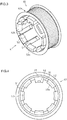
- the driven pulley 42 has a cylindrical radially outer portion 42a around which the belt 43 is wound, a radially inner portion 42b attached so as to be rotatable together with the ball screw nut 31, and a connection portion 42c that connects the radially outer portion 42a and the radially inner portion 42b to each other in the radial direction at their second end portions (right ends in FIG. 2 ).
- the radially inner portion 42b is provided with a plurality of (eight) slits S (clearances) at equal intervals in the circumferential direction.
- the slits S extend in the axial direction of the driven pulley 42.
- Seven retention portions 52 and one key portion 53 are provided at portions of the radially inner portion 42b between the slits S.
- the retention portions 52 and the key portion 53 also extend in the axial direction of the driven pulley 42.
- Lug portions 52a are provided at the distal ends (end portions opposite to the connection portion 42c) of the retention portions 52.
- the outer peripheral surface of the ball screw nut 31 is provided with a key groove 54 that extends in the axial direction of the ball screw nut 31 over a certain range from the second end portion of the ball screw nut 31.
- the key groove 54 is preferably provided so as to be deeper than the groove 50.
- the key portion 53 preferably projects in the radial direction more than the lug portions 52a.
- the lug portions 52a of the retention portions 52 are fitted with the groove 50 of the ball screw nut 31.
- the key portion 53 is engaged with the key groove 54.
- the distal end (an end portion opposite to the connection portion 42c) of the key portion 53 abuts against an abutment portion 54a.
- the abutment portion 54a is provided orthogonally to the axial direction of the ball screw nut 31.
- the ball screw nut 31 When attaching the driven pulley 42 to the outer peripheral surface of the ball screw nut 31, the ball screw nut 31 is relatively inserted into the radially inner portion 42b to elastically deform the retention portions 52, and the driven pulley 42 is pressed from the second end portion of the ball screw nut 31 toward the first end portion with the lug portions 52a at the distal ends of the retention portions 52 pushed radially outward.
- the lug portions 52a are moved to a position corresponding to the groove 50, the retention portions 52 are elastically returned to the original position in the radial direction. Consequently, the lug portions 52a are fitted with the groove 50. With the lug portions 52a engaged with the inner wall surface of the groove 50 in the axial direction, movement of the driven pulley 42 with respect to the ball screw nut 31 in the axial direction is suppressed.
- the key portion 53 is fitted with the key groove 54 to be guided.
- the rotational force of the driven pulley 42 is transferred to the ball screw nut 31 with the key portion 53 engaged with the key groove 54 of the ball screw nut 31 in the circumferential direction. Therefore, the ball screw nut 31 is rotated together with the driven pulley 42.
- a depth D and a width W1 (axial length) of the groove 50 and a height H and a width W2 of the lug portions 52a are determined in consideration of the difference between the coefficient of thermal expansion of the ball screw nut 31 and the coefficient of thermal expansion of the driven pulley 42 and the shearing stress of the lug portions 52a.
- the height H and the width W2 of the lug portions 52a are increased along with a temperature rise, and therefore the lug portions 52a are expanded outward in the circumferential direction.
- the widths W1 and W2 are set such that the width W2 of the lug portions 52a does not exceed the width W1 of the groove 50 at the upper limit of the use temperature range, and such that the width W2 is not excessively smaller than the width W1 at normal or low temperatures.
- a clearance is provided between the groove 50 and the lug portions 52a at normal temperature (at low temperature).
- the lug portions 52a are thermally expanded more than the groove 50, which leaves substantially no clearance between the groove 50 and the lug portions 52a.
- a tapered surface is preferably provided on the inner peripheral side of the distal ends of the lug portions 52a.
- the depth D of the groove 50 and the height H of the lug portions 52a are set such that the lug portions 52a are not shear-fractured by a shearing stress in correspondence with the tapered surface of the lug portions 52a.
- FIG. 6 illustrates the relationship between the groove 50 and the lug portion 52a at the time when the temperature is varied.
- thermal expansion of the ball screw nut 31 is not taken into consideration, and only thermal expansion of the lug portions 52a of the driven pulley 42 which is a resin member is taken into consideration.
- the continuous line indicates the lug portion 52a at normal temperature
- the long dashed short dashed line indicates the lug portion 52a at low temperature
- the long dashed double-short dashed line indicates the lug portion 52a at high temperature.
- the depth of fitting of the lug portion 52a with the groove 50 becomes smaller.
- the depth of fitting of the lug portion 52a with the groove 50 becomes larger.
- the effective area for receiving a shearing stress that acts on the lug portion 52a when the driven pulley 42 is moved in the axial direction with respect to the ball screw nut 31 becomes smaller. Therefore, the lug portion 52a is shear-fractured more easily along with a temperature rise.
- the height H of the lug portion 52a so as not to be excessively high with respect to the depth D of the groove 50 such that the lug portion 52a is not shear-fractured even in the case where the lug portion 52a is thermally expanded or even when the driven pulley 42 is urged to be moved in the axial direction with respect to the ball screw nut 31.
- an end surface of the groove 50 in the axial direction is provided in parallel with a direction that is orthogonal to the axial direction. However, such an end surface may be tilted.
- one end surface 50a of the groove 50 in the axial direction may be provided as tilted with respect to a direction (up-down direction in FIG. 7 ) that is orthogonal to the axial direction.
- a lug portion 52b is preferably also tilted like an arrow head in correspondence with the one end surface 50a of the groove 50.
- the annular groove 50 is provided in the outer peripheral surface of the ball screw nut 31.
- the present invention is not limited thereto.
- the outer peripheral surface of the ball screw nut 31 may be provided with a groove that partially extends along such a peripheral surface.
- the driven pulley 42 has the radially outer portion 42a, the radially inner portion 42b, and the connection portion 42c.
- the present invention is not limited thereto.
- the driven pulley 42 may have a single cylindrical structure in which the radially outer portion 42a and the radially inner portion 42b are connected to each other over the entire region in the axial direction.
- the driven pulley 42 and the ball screw nut 31 are fixed so as to be rotatable together, with the lug portions 52a and the key portion 53 which are provided on the inner peripheral surface of the driven pulley 42 fitted with the groove 50 and the key groove 54 which are provided in the outer peripheral surface of the ball screw nut 31.
- the lug portions 52a are shaped so as to be adjacent to a side surface of the body of the thick-walled driven pulley 42, and therefore it is difficult to elastically deform the lug portions 52a.
- the abutment portion 51 is provided on the outer peripheral surface of the ball screw nut 31.
- the abutment portion 51 may not be provided.
- the driven pulley 42 may abut against an inner ring of the bearing 33 in the axial direction, for example.
- the distal end of the key portion 53 of the driven pulley 42 may abut against an end portion of the key groove 54 on the deeper side.
- the distal end of the key portion 53 abuts against the abutment portion 51.
- the distal ends of the retention portions 52 in place of the distal end of the key portion 53, may abut against the abutment portion 51.
- the annular groove 50 for retention is provided between the first end portion and the second end portion of the ball screw nut 31 and on the side of the first end portion.
- an annular groove 60 may be provided at the second end portion (right end in FIG. 9 ) of the ball screw nut 31.
- a connection portion 42c that connects the radially outer portion 42a and the radially inner portion 42b to each other in the radial direction is provided on the side of the first end.
- the radially outer portion 42a and the radially inner portion 42b of the driven pulley 42 extend from the connection portion 42c toward the second end portion in the axial direction of the driven pulley 42.
- retention portions are provided at an end portion of the driven pulley 42 opposite to the bearing 33 when the driven pulley 42 is assembled to the ball screw nut 31.
- the lug portions 52a are fitted with the groove 60 at the same time as the driven pulley 42 is completely fitted with the ball screw nut 31.
- the lug portion 52a is provided with a tapered surface in order to improve assemblability.
- a tapered surface may be provided at the outer periphery of an end portion of the ball screw nut 31.
- the lug portions 52a are not provided with a tapered surface so that the lug portions 52a have a rectangular sectional shape along the axis of the driven pulley 42.
- connection portion 42c connects the radially outer portion 42a and the radially inner portion 42b to each other in the radial direction at the second end portion.
- connection portion 42c may connect the radially outer portion 42a and the radially inner portion 42b to each other in the radial direction at the first end portion (see FIG. 9 ).
- the slits S may be provided only in a certain range from the distal ends of the retention portions 52 and the key portion 53 toward the connection portion 42c (see FIG. 10 ).
- eight slits S are provided in the radially inner portion 42b of the driven pulley 42 at equal intervals in the circumferential direction.
- any number of slits S may be provided, or no slits S may be provided.
- the number of slits S can be changed freely in accordance with the ease of elastic deformation required for the radially inner portion 42b. It is only necessary that one or more retention portions 52 should be provided in the circumferential direction. Two or more key portions 53 may be provided in the circumferential direction, or no key portions 53 may be provided.
- the ball screw nut 31 is provided with the key groove 54, and the driven pulley 42 is provided with the key portion 53.
- a different rotation locking structure may be provided instead. If only torque in such a range that rotation of the driven pulley 42 relative to the ball screw nut 31 is not caused is applied to the driven pulley 42, a fastening structure that press-fits the inner peripheral surface of the driven pulley 42 with the outer peripheral surface of the ball screw nut 31 may be provided.
- the abutment portion 51 is provided with a surface that is orthogonal to the axial direction of the ball screw nut 31.
- the present invention is not limited thereto.
- the abutment portion 51 may include an oblique surface, and such a surface may be provided so as to abut against the driven pulley 42.
- the abutment portion 54a may also be provided obliquely with respect to the axial direction of the ball screw nut 31.
- the present invention is embodied as the EPS device 1 which applies an assist force to the rack shaft 12 using the motor 20 which has the rotary shaft 21 which is disposed in parallel with the rack shaft 12.
- the present invention is not limited thereto. That is, the present invention may be embodied as a steering system that includes the ball screw device 30 and the speed reducer 40.
- the present invention is applied to a steering system that assists linear motion of the rack shaft 12, which occurs in conjunction with a steering operation, utilizing the rotational force of the motor 20.
- the present invention may be applied to a steer-by-wire (SBW) steering system that includes no mechanical coupling between the steering wheel 10 and the rack shaft 12.
- SBW steer-by-wire
- the present invention may be embodied not only as a front-wheel steering system but also as a rear-wheel steering system or a four-wheel steering (4WS) system.
Landscapes
- Engineering & Computer Science (AREA)
- Mechanical Engineering (AREA)
- General Engineering & Computer Science (AREA)
- Chemical & Material Sciences (AREA)
- Combustion & Propulsion (AREA)
- Transportation (AREA)
- Power Steering Mechanism (AREA)
- Devices For Conveying Motion By Means Of Endless Flexible Members (AREA)
- Transmission Devices (AREA)
Applications Claiming Priority (1)
| Application Number | Priority Date | Filing Date | Title |
|---|---|---|---|
| JP2017074476A JP2018176815A (ja) | 2017-04-04 | 2017-04-04 | ステアリング装置 |
Publications (1)
| Publication Number | Publication Date |
|---|---|
| EP3385572A1 true EP3385572A1 (de) | 2018-10-10 |
Family
ID=61868419
Family Applications (1)
| Application Number | Title | Priority Date | Filing Date |
|---|---|---|---|
| EP18165383.3A Withdrawn EP3385572A1 (de) | 2017-04-04 | 2018-04-03 | Lenksystem |
Country Status (4)
| Country | Link |
|---|---|
| US (1) | US10661824B2 (de) |
| EP (1) | EP3385572A1 (de) |
| JP (1) | JP2018176815A (de) |
| CN (1) | CN108688715A (de) |
Cited By (1)
| Publication number | Priority date | Publication date | Assignee | Title |
|---|---|---|---|---|
| DE102020202301A1 (de) | 2020-02-24 | 2021-08-26 | Zf Friedrichshafen Ag | Lenkgetriebe für ein Fahrzeug |
Families Citing this family (7)
| Publication number | Priority date | Publication date | Assignee | Title |
|---|---|---|---|---|
| DE102019115542A1 (de) * | 2018-06-08 | 2019-12-12 | Steering Solutions Ip Holding Corporation | Wartungsfähiger aggregat-riemenantrieb |
| US10865862B2 (en) * | 2018-08-27 | 2020-12-15 | Hitachi Automotive Systems Americas, Inc. | Pulley and ball nut assembly |
| US10995799B2 (en) * | 2019-04-02 | 2021-05-04 | Steering Solutions Ip Holding Corporation | Self-retaining pulley for steering assembly |
| DE102019118473A1 (de) * | 2019-07-09 | 2021-01-14 | Knorr-Bremse Systeme für Nutzfahrzeuge GmbH | Elektromechanischer Getriebe- und/oder Kupplungsaktuator |
| JP7160012B2 (ja) * | 2019-10-03 | 2022-10-25 | 株式会社デンソー | 電子制御装置 |
| DE102020205971A1 (de) * | 2020-05-12 | 2021-11-18 | Zf Automotive Germany Gmbh | Riemenscheibe und Lenkgetriebe |
| KR20220146829A (ko) * | 2021-04-26 | 2022-11-02 | 에이치엘만도 주식회사 | 자동차의 조향장치 |
Citations (5)
| Publication number | Priority date | Publication date | Assignee | Title |
|---|---|---|---|---|
| DE102007049114A1 (de) * | 2007-10-12 | 2009-04-16 | Volkswagen Ag | Zahnriemenrad einer elektromechanischen Lenkung mit Kugelgewindemutter |
| EP2128496A2 (de) * | 2008-05-26 | 2009-12-02 | IMS Gear GmbH | Zahnriemenrad für einen Zahnriemenantrieb |
| US20140090921A1 (en) | 2012-09-28 | 2014-04-03 | Steering Solutions Ip Holding Corporation | Nylon resin driven pulley |
| US20140100070A1 (en) * | 2012-10-05 | 2014-04-10 | Mando Corporation | Pulley structure of belt type electric power steering gear |
| WO2015071057A1 (de) * | 2013-11-14 | 2015-05-21 | Trw Automotive Gmbh | Getriebebaugruppe für eine elektromechanische servolenkung |
Family Cites Families (11)
| Publication number | Priority date | Publication date | Assignee | Title |
|---|---|---|---|---|
| JPH0662092B2 (ja) * | 1986-04-11 | 1994-08-17 | 本田技研工業株式会社 | 電動式パワ−ステアリング装置 |
| JP3960474B2 (ja) * | 2002-04-01 | 2007-08-15 | パイオニア株式会社 | スピーカ用エッジ及びその形成方法 |
| DE102004058963A1 (de) * | 2004-12-08 | 2006-06-14 | Schaeffler Kg | Zahnriemenscheibe |
| KR101450326B1 (ko) * | 2011-08-31 | 2014-10-21 | 주식회사 만도 | 벨트식 전동장치 및 이를 구비한 랙구동형 동력 보조 조향장치 |
| KR101454505B1 (ko) * | 2011-11-17 | 2014-10-28 | 주식회사 만도 | 랙구동형 동력 보조 조향장치 |
| US9168948B2 (en) * | 2013-06-04 | 2015-10-27 | Jtekt Corporation | Steering system |
| JP6149612B2 (ja) * | 2013-08-29 | 2017-06-21 | 株式会社ジェイテクト | 操舵装置 |
| JP2017137027A (ja) * | 2016-02-05 | 2017-08-10 | 株式会社ジェイテクト | ステアリング装置及びアイドラプーリの配置の方法 |
| JP6728974B2 (ja) * | 2016-05-23 | 2020-07-22 | 株式会社ジェイテクト | ボールねじ機構及びステアリング装置 |
| JP2018202919A (ja) * | 2017-05-31 | 2018-12-27 | 株式会社ジェイテクト | ステアリング装置 |
| JP2019182266A (ja) * | 2018-04-12 | 2019-10-24 | 株式会社ジェイテクト | 車両用操舵装置 |
-
2017
- 2017-04-04 JP JP2017074476A patent/JP2018176815A/ja not_active Ceased
-
2018
- 2018-03-28 US US15/938,686 patent/US10661824B2/en active Active
- 2018-04-02 CN CN201810281867.7A patent/CN108688715A/zh active Pending
- 2018-04-03 EP EP18165383.3A patent/EP3385572A1/de not_active Withdrawn
Patent Citations (5)
| Publication number | Priority date | Publication date | Assignee | Title |
|---|---|---|---|---|
| DE102007049114A1 (de) * | 2007-10-12 | 2009-04-16 | Volkswagen Ag | Zahnriemenrad einer elektromechanischen Lenkung mit Kugelgewindemutter |
| EP2128496A2 (de) * | 2008-05-26 | 2009-12-02 | IMS Gear GmbH | Zahnriemenrad für einen Zahnriemenantrieb |
| US20140090921A1 (en) | 2012-09-28 | 2014-04-03 | Steering Solutions Ip Holding Corporation | Nylon resin driven pulley |
| US20140100070A1 (en) * | 2012-10-05 | 2014-04-10 | Mando Corporation | Pulley structure of belt type electric power steering gear |
| WO2015071057A1 (de) * | 2013-11-14 | 2015-05-21 | Trw Automotive Gmbh | Getriebebaugruppe für eine elektromechanische servolenkung |
Cited By (1)
| Publication number | Priority date | Publication date | Assignee | Title |
|---|---|---|---|---|
| DE102020202301A1 (de) | 2020-02-24 | 2021-08-26 | Zf Friedrichshafen Ag | Lenkgetriebe für ein Fahrzeug |
Also Published As
| Publication number | Publication date |
|---|---|
| JP2018176815A (ja) | 2018-11-15 |
| CN108688715A (zh) | 2018-10-23 |
| US20180281843A1 (en) | 2018-10-04 |
| US10661824B2 (en) | 2020-05-26 |
Similar Documents
| Publication | Publication Date | Title |
|---|---|---|
| EP3385572A1 (de) | Lenksystem | |
| EP3388309B1 (de) | Lenksystem | |
| US8863598B2 (en) | Electric power steering system | |
| US8434585B2 (en) | Electric power steering system and vehicle steering system | |
| EP3581465B1 (de) | Steer-by-wire-servolenkvorrichtung | |
| CN107719464B (zh) | 转向装置 | |
| EP2431634B1 (de) | Schneckenantrieb | |
| EP2711575A1 (de) | Rotationsübertragungsvorrichtung, Fahrzeuglenksystem und Zwischenwelle | |
| EP3424798B1 (de) | Lenksystem und verfahren zur herstellung eines lenksystems | |
| US10196084B2 (en) | Rack assist type electric power steering apparatus | |
| US20150274193A1 (en) | Steering apparatus and bearing member | |
| US8784253B2 (en) | Transmission ratio variable device | |
| EP3252345B1 (de) | Kugelgewindevorrichtung und lenksystem | |
| CN108928384B (zh) | 电动助力转向设备及其组装方法 | |
| EP3459821A1 (de) | Lenksystem | |
| US11384827B2 (en) | Electric power steering polymer drive pulley | |
| EP1813507B1 (de) | Elektrische Servolenkung | |
| JP6673308B2 (ja) | ステアリング用トルク伝達軸 | |
| JP2017219071A (ja) | ボールねじ装置およびステアリング装置 | |
| US9580101B2 (en) | Electric power steering system | |
| US11052937B2 (en) | Splined component assembly and method | |
| JP2019107989A (ja) | ステアリング装置 | |
| KR20230073709A (ko) | 랙구동형 동력 보조 조향장치 | |
| CN114954636A (zh) | 齿条驱动式动力辅助转向设备 | |
| JP2021196044A (ja) | ボールねじ装置、およびステアリング装置 |
Legal Events
| Date | Code | Title | Description |
|---|---|---|---|
| PUAI | Public reference made under article 153(3) epc to a published international application that has entered the european phase |
Free format text: ORIGINAL CODE: 0009012 |
|
| STAA | Information on the status of an ep patent application or granted ep patent |
Free format text: STATUS: THE APPLICATION HAS BEEN PUBLISHED |
|
| AK | Designated contracting states |
Kind code of ref document: A1 Designated state(s): AL AT BE BG CH CY CZ DE DK EE ES FI FR GB GR HR HU IE IS IT LI LT LU LV MC MK MT NL NO PL PT RO RS SE SI SK SM TR |
|
| AX | Request for extension of the european patent |
Extension state: BA ME |
|
| STAA | Information on the status of an ep patent application or granted ep patent |
Free format text: STATUS: REQUEST FOR EXAMINATION WAS MADE |
|
| 17P | Request for examination filed |
Effective date: 20190304 |
|
| RBV | Designated contracting states (corrected) |
Designated state(s): AL AT BE BG CH CY CZ DE DK EE ES FI FR GB GR HR HU IE IS IT LI LT LU LV MC MK MT NL NO PL PT RO RS SE SI SK SM TR |
|
| STAA | Information on the status of an ep patent application or granted ep patent |
Free format text: STATUS: REQUEST FOR EXAMINATION WAS MADE |
|
| RIC1 | Information provided on ipc code assigned before grant |
Ipc: F16H 25/24 20060101AFI20201214BHEP Ipc: F16H 25/20 20060101ALN20201214BHEP Ipc: F16H 55/17 20060101ALI20201214BHEP Ipc: B62D 5/04 20060101ALI20201214BHEP Ipc: F16H 55/48 20060101ALN20201214BHEP |
|
| GRAP | Despatch of communication of intention to grant a patent |
Free format text: ORIGINAL CODE: EPIDOSNIGR1 |
|
| STAA | Information on the status of an ep patent application or granted ep patent |
Free format text: STATUS: GRANT OF PATENT IS INTENDED |
|
| INTG | Intention to grant announced |
Effective date: 20210205 |
|
| STAA | Information on the status of an ep patent application or granted ep patent |
Free format text: STATUS: THE APPLICATION IS DEEMED TO BE WITHDRAWN |
|
| 18D | Application deemed to be withdrawn |
Effective date: 20210616 |