EP3385513A1 - Variabler ventiltrieb - Google Patents
Variabler ventiltrieb Download PDFInfo
- Publication number
- EP3385513A1 EP3385513A1 EP18165461.7A EP18165461A EP3385513A1 EP 3385513 A1 EP3385513 A1 EP 3385513A1 EP 18165461 A EP18165461 A EP 18165461A EP 3385513 A1 EP3385513 A1 EP 3385513A1
- Authority
- EP
- European Patent Office
- Prior art keywords
- cam
- holder
- pivot axis
- variable valve
- camshaft
- Prior art date
- Legal status (The legal status is an assumption and is not a legal conclusion. Google has not performed a legal analysis and makes no representation as to the accuracy of the status listed.)
- Granted
Links
- 230000005540 biological transmission Effects 0.000 claims abstract description 26
- 238000002485 combustion reaction Methods 0.000 claims abstract description 13
- 230000000694 effects Effects 0.000 claims description 8
- 238000006073 displacement reaction Methods 0.000 claims description 7
- 230000009849 deactivation Effects 0.000 claims description 5
- 230000006837 decompression Effects 0.000 claims description 5
- 210000003746 feather Anatomy 0.000 claims description 2
- 238000012546 transfer Methods 0.000 description 3
- 230000006835 compression Effects 0.000 description 2
- 238000007906 compression Methods 0.000 description 2
- 238000010276 construction Methods 0.000 description 2
- 230000001419 dependent effect Effects 0.000 description 1
- 238000013461 design Methods 0.000 description 1
- 238000011161 development Methods 0.000 description 1
- 230000018109 developmental process Effects 0.000 description 1
- 230000005611 electricity Effects 0.000 description 1
- 230000002349 favourable effect Effects 0.000 description 1
- 239000012530 fluid Substances 0.000 description 1
- 239000000446 fuel Substances 0.000 description 1
- 238000009434 installation Methods 0.000 description 1
- 230000010354 integration Effects 0.000 description 1
- 238000012423 maintenance Methods 0.000 description 1
- 238000004519 manufacturing process Methods 0.000 description 1
- KJFBVJALEQWJBS-XUXIUFHCSA-N maribavir Chemical compound CC(C)NC1=NC2=CC(Cl)=C(Cl)C=C2N1[C@H]1O[C@@H](CO)[C@H](O)[C@@H]1O KJFBVJALEQWJBS-XUXIUFHCSA-N 0.000 description 1
- 238000012986 modification Methods 0.000 description 1
- 230000004048 modification Effects 0.000 description 1
Images


Classifications
-
- F—MECHANICAL ENGINEERING; LIGHTING; HEATING; WEAPONS; BLASTING
- F01—MACHINES OR ENGINES IN GENERAL; ENGINE PLANTS IN GENERAL; STEAM ENGINES
- F01L—CYCLICALLY OPERATING VALVES FOR MACHINES OR ENGINES
- F01L1/00—Valve-gear or valve arrangements, e.g. lift-valve gear
- F01L1/12—Transmitting gear between valve drive and valve
-
- F—MECHANICAL ENGINEERING; LIGHTING; HEATING; WEAPONS; BLASTING
- F01—MACHINES OR ENGINES IN GENERAL; ENGINE PLANTS IN GENERAL; STEAM ENGINES
- F01L—CYCLICALLY OPERATING VALVES FOR MACHINES OR ENGINES
- F01L13/00—Modifications of valve-gear to facilitate reversing, braking, starting, changing compression ratio, or other specific operations
- F01L13/0015—Modifications of valve-gear to facilitate reversing, braking, starting, changing compression ratio, or other specific operations for optimising engine performances by modifying valve lift according to various working parameters, e.g. rotational speed, load, torque
- F01L13/0036—Modifications of valve-gear to facilitate reversing, braking, starting, changing compression ratio, or other specific operations for optimising engine performances by modifying valve lift according to various working parameters, e.g. rotational speed, load, torque the valves being driven by two or more cams with different shape, size or timing or a single cam profiled in axial and radial direction
-
- F—MECHANICAL ENGINEERING; LIGHTING; HEATING; WEAPONS; BLASTING
- F01—MACHINES OR ENGINES IN GENERAL; ENGINE PLANTS IN GENERAL; STEAM ENGINES
- F01L—CYCLICALLY OPERATING VALVES FOR MACHINES OR ENGINES
- F01L1/00—Valve-gear or valve arrangements, e.g. lift-valve gear
- F01L1/02—Valve drive
- F01L1/04—Valve drive by means of cams, camshafts, cam discs, eccentrics or the like
- F01L1/047—Camshafts
-
- F—MECHANICAL ENGINEERING; LIGHTING; HEATING; WEAPONS; BLASTING
- F01—MACHINES OR ENGINES IN GENERAL; ENGINE PLANTS IN GENERAL; STEAM ENGINES
- F01L—CYCLICALLY OPERATING VALVES FOR MACHINES OR ENGINES
- F01L1/00—Valve-gear or valve arrangements, e.g. lift-valve gear
- F01L1/12—Transmitting gear between valve drive and valve
- F01L1/18—Rocking arms or levers
- F01L1/181—Centre pivot rocking arms
-
- F—MECHANICAL ENGINEERING; LIGHTING; HEATING; WEAPONS; BLASTING
- F01—MACHINES OR ENGINES IN GENERAL; ENGINE PLANTS IN GENERAL; STEAM ENGINES
- F01L—CYCLICALLY OPERATING VALVES FOR MACHINES OR ENGINES
- F01L1/00—Valve-gear or valve arrangements, e.g. lift-valve gear
- F01L1/46—Component parts, details, or accessories, not provided for in preceding subgroups
-
- F—MECHANICAL ENGINEERING; LIGHTING; HEATING; WEAPONS; BLASTING
- F01—MACHINES OR ENGINES IN GENERAL; ENGINE PLANTS IN GENERAL; STEAM ENGINES
- F01L—CYCLICALLY OPERATING VALVES FOR MACHINES OR ENGINES
- F01L1/00—Valve-gear or valve arrangements, e.g. lift-valve gear
- F01L1/12—Transmitting gear between valve drive and valve
- F01L1/18—Rocking arms or levers
- F01L1/185—Overhead end-pivot rocking arms
-
- F—MECHANICAL ENGINEERING; LIGHTING; HEATING; WEAPONS; BLASTING
- F01—MACHINES OR ENGINES IN GENERAL; ENGINE PLANTS IN GENERAL; STEAM ENGINES
- F01L—CYCLICALLY OPERATING VALVES FOR MACHINES OR ENGINES
- F01L13/00—Modifications of valve-gear to facilitate reversing, braking, starting, changing compression ratio, or other specific operations
- F01L13/08—Modifications of valve-gear to facilitate reversing, braking, starting, changing compression ratio, or other specific operations for decompression, e.g. during starting; for changing compression ratio
-
- F—MECHANICAL ENGINEERING; LIGHTING; HEATING; WEAPONS; BLASTING
- F01—MACHINES OR ENGINES IN GENERAL; ENGINE PLANTS IN GENERAL; STEAM ENGINES
- F01L—CYCLICALLY OPERATING VALVES FOR MACHINES OR ENGINES
- F01L1/00—Valve-gear or valve arrangements, e.g. lift-valve gear
- F01L1/12—Transmitting gear between valve drive and valve
- F01L1/18—Rocking arms or levers
- F01L2001/186—Split rocking arms, e.g. rocker arms having two articulated parts and means for varying the relative position of these parts or for selectively connecting the parts to move in unison
-
- F—MECHANICAL ENGINEERING; LIGHTING; HEATING; WEAPONS; BLASTING
- F01—MACHINES OR ENGINES IN GENERAL; ENGINE PLANTS IN GENERAL; STEAM ENGINES
- F01L—CYCLICALLY OPERATING VALVES FOR MACHINES OR ENGINES
- F01L13/00—Modifications of valve-gear to facilitate reversing, braking, starting, changing compression ratio, or other specific operations
- F01L13/0005—Deactivating valves
- F01L2013/001—Deactivating cylinders
-
- F—MECHANICAL ENGINEERING; LIGHTING; HEATING; WEAPONS; BLASTING
- F01—MACHINES OR ENGINES IN GENERAL; ENGINE PLANTS IN GENERAL; STEAM ENGINES
- F01L—CYCLICALLY OPERATING VALVES FOR MACHINES OR ENGINES
- F01L13/00—Modifications of valve-gear to facilitate reversing, braking, starting, changing compression ratio, or other specific operations
- F01L2013/10—Auxiliary actuators for variable valve timing
- F01L2013/101—Electromagnets
-
- F—MECHANICAL ENGINEERING; LIGHTING; HEATING; WEAPONS; BLASTING
- F01—MACHINES OR ENGINES IN GENERAL; ENGINE PLANTS IN GENERAL; STEAM ENGINES
- F01L—CYCLICALLY OPERATING VALVES FOR MACHINES OR ENGINES
- F01L2305/00—Valve arrangements comprising rollers
-
- Y—GENERAL TAGGING OF NEW TECHNOLOGICAL DEVELOPMENTS; GENERAL TAGGING OF CROSS-SECTIONAL TECHNOLOGIES SPANNING OVER SEVERAL SECTIONS OF THE IPC; TECHNICAL SUBJECTS COVERED BY FORMER USPC CROSS-REFERENCE ART COLLECTIONS [XRACs] AND DIGESTS
- Y02—TECHNOLOGIES OR APPLICATIONS FOR MITIGATION OR ADAPTATION AGAINST CLIMATE CHANGE
- Y02T—CLIMATE CHANGE MITIGATION TECHNOLOGIES RELATED TO TRANSPORTATION
- Y02T10/00—Road transport of goods or passengers
- Y02T10/10—Internal combustion engine [ICE] based vehicles
- Y02T10/12—Improving ICE efficiencies
Definitions
- the invention relates to a variable valve train for an internal combustion engine and a motor vehicle with a variable valve train.
- variable valve trains can be used.
- Variable valve trains can additionally or alternatively adapt the valve lifts of the charge exchange valves.
- a well-known variable valve train is the so-called Audi Valvelift System (AVS).
- a cam carrier is arranged axially displaceably on a camshaft.
- the cam carrier has a first cam and a second cam which is offset in the longitudinal direction of the camshaft.
- the first cam and the second cam differ, for example, in a contour and / or are circumferentially offset from each other.
- the cam carrier Via an actuator device, the cam carrier can be moved between a first axial position and a second axial position. In the first axial position of the cam carrier, a charge exchange valve via a transmission lever in operative connection with the first cam. In the second axial position of the cam carrier, the charge exchange valve is in operative connection with the second cam via the transfer lever.
- the known system may have the disadvantage that a relatively large mass must be moved in the form of the cam carrier with the double cam.
- the relatively large mass can negatively affect the achievable speed in switching operations between the cams.
- the invention is therefore based on the object to provide an improved variable valve train, which overcomes in particular the disadvantages of the prior art.
- variable valve train for an internal combustion engine according to the independent claim.
- the variable valve train has at least one lift valve, in particular a charge exchange valve, and a camshaft.
- the camshaft has a first cam and a second cam staggered in a longitudinal direction of the camshaft.
- a cam contour of the first cam is different from a cam contour of the second cam and / or the first cam and the second cam are arranged offset in a circumferential direction about a longitudinal axis of the camshaft.
- the variable valve train further comprises a transmission lever, which is arranged in operative connection between the at least one lift valve and the camshaft for actuating the at least one lift valve on.
- the transmission lever has a pivot axis, a holder and a cam follower.
- the holder is pivotally mounted about the pivot axis.
- the holder holds the cam follower.
- the holder is mounted axially displaceable parallel to the pivot axis and / or parallel to the camshaft, so that the cam follower optionally follows the cam contour of the first cam
- the holder Since the holder holds only the cam follower, it may be compact and therefore have a low mass. This can in particular allow fast switching operations between the first cam and the second cam.
- the first cam and the second cam may be configured to effect different operations (timing and / or strokes) of the associated lift valve.
- the holder may be displaceable between a first axial position, in which there is an operative connection between the charge exchange valve and the first cam, and a second axial position, in which there is an operative connection between the charge exchange valve and the second cam.
- first axial position and the second axial position may be defined (fixed) by a corresponding first stop and a corresponding second stop for the holder.
- the internal combustion engine can be used, for example, in a motor vehicle, in particular a commercial vehicle such as a truck, a bus, a construction machine or an agricultural machine.
- the internal combustion engine can also be used in a rail vehicle, as a marine engine or as a stationary engine, for example, to generate electricity.
- the holder is mounted directly on the pivot axis pivotable and axially displaceable.
- the direct storage on the pivot axis can allow a particularly simple structure.
- the transmission lever may further comprise a support member which is pivotally mounted about the pivot axis and the holder supports axially displaceable.
- the interposition of a carrier component may allow a particularly compact design of the holder.
- the carrier component or the holder (in particular if no carrier component is present) has an axle bore for the pivot axis.
- the connection between the axle bore and pivot axis allows a particularly simple rotatable mounting of the carrier component or the holder on the pivot axis.
- the support member is rotatably connected to the bracket about the pivot axis.
- the connection can have a positive connection between the holder and the carrier component. This has the advantage that additional means for the rotationally fixed connection of the carrier component and the holder can be saved.
- the support member in a cross-sectional plane perpendicular to a longitudinal direction of the pivot axis to the pivot axis rotationally asymmetric (non-rotationally symmetric) outer contour.
- the holder in a cross-sectional plane perpendicular to a longitudinal direction of the pivot axis, has a rotationally asymmetrical (non-rotationally symmetrical) inner contour to the pivot axis. This allows a rotationally fixed connection between the support member and the holder without providing additional means.
- the outer contour and / or the inner contour has a profiling, preferably a splined profile or tooth profile.
- the outer contour and / or the inner contour in particular has a polygonal shape, for example a rectangular shape. Such contours are easy to manufacture and reliable in the application.
- the holder only partially surrounds the carrier component.
- an inner contour of the holder for connection to an outer contour of the carrier component does not have to be closed.
- the support member is axially secured on the pivot axis, for example by a secured on the pivot axis locking ring or a feather key. This prevents a displacement of the support member on the pivot axis.
- the holder and / or the carrier component has an actuating portion for actuating the at least one lift valve.
- the operating portion may be disposed on a side opposite to the cam follower with respect to the pivot axis or on the same side as the cam follower with respect to the pivot axis.
- the holder has a fork region with two opposite projections.
- an axis of rotation, on which the cam follower is rotatably mounted extends between the projections.
- the fork area allows a particularly compact storage of the cam follower.
- the cam follower may be formed as a roller, which is rotatably supported by the holder in particular. This has the advantage that the friction in the valve train can be reduced.
- variable valve train further comprises an actuator device which is adapted to axially displace the holder parallel to the pivot axis and / or to the camshaft.
- the actuator device can move the holder between the first axial position and the second axial position.
- the actuator device is designed as a pneumatic, hydraulic, electromechanical and / or electromagnetic actuator device.
- the actuator device is connected directly or indirectly, for example via a linkage, to the holder.
- the actuator device is at least partially integrated in the transmission lever or arranged externally of the transmission lever.
- An external arrangement can facilitate installation and maintenance.
- An integration may allow for a more compact construction.
- the actuator device for displacing the holder engages on a side surface of the holder, which extends perpendicular to a longitudinal direction of the pivot axis.
- the actuator device engages a projection (or both projections) of a fork region of the holder.
- the actuator device is designed and / or is so controlled that the cam follower is moved only between a base circle of the first cam and a base circle of the second cam.
- the camshaft has at least one further cam, which is arranged offset in a longitudinal direction of the camshaft to the first cam and the second cam.
- a cam contour of each further cam is different from a cam contour of the first cam and a cam contour of the second cam alternatively or additionally, each further cam is arranged in a circumferential direction about a longitudinal axis of the camshaft offset from the first cam and the second cam.
- the cam follower follows by a displacement of the bracket additionally optionally the cam contour of each additional cam.
- the transmission lever is designed as a drag lever or a rocker arm.
- the transmission lever in various valve train systems, for example, with overhead camshaft or with underlying camshaft, integrated.
- the at least one lift valve is an intake valve of the internal combustion engine and the first cam effects a normal operation and / or the second cam effects a miller operation, an Atkinson operation, a thermal management operation, a decompression operation or a cylinder deactivation.
- the normal operation corresponds to opening of the intake valve according to a diesel or Otto cycle in which the intake valve is opened during the intake stroke.
- the intake valve is closed earlier relative to it, which reduces the amount of charge air.
- Atkinson mode the inlet valve is closed later relative to normal operation. This also reduces the charge air quantity.
- the at least one lift valve is an exhaust valve of the internal combustion engine and the first cam effects a normal operation and / or the second cam effects an engine brake operation, a thermal management operation, a decompression operation or a cylinder deactivation.
- the normal operation corresponds to an opening of the exhaust valve according to a diesel or Otto cycle in which the exhaust valve is open during the exhaust stroke.
- the exhaust valve may be opened at the end of the compression stroke and / or exhaust stroke may be opened at the end.
- the heat balance of the internal combustion engine is specifically influenced compared to normal operation, in order, for example, to increase an exhaust gas temperature.
- the lift valve is kept open.
- the lift valve is not actuated.
- the second cam may be a zero cam.
- the invention further relates to a motor vehicle, in particular a utility vehicle, with a variable valve train as disclosed herein.
- FIGS. 1 and 2 show a variable valve train 10 in different views.
- the variable valve train 10 has a camshaft 12, a transmission lever 14 and a lift valve 16 (only partially with dashed lines in FIG. 1 and 2 indicated).
- the lift valve is in particular a charge exchange valve, for example an intake valve or an exhaust valve, of a cylinder of an internal combustion engine.
- the camshaft 12 may be formed as an overhead or a bottom camshaft.
- the camshaft 12 has a first cam 18 and a second cam 20.
- the first cam 18 is disposed in a longitudinal direction of the camshaft 12 adjacent to the second cam 20.
- the first cam 18 abuts the second cam 20.
- the cams 18 and 20 may be spaced apart in a longitudinal direction of the camshaft 12.
- the cams 18 and 20 are designed to operate the lift valve 16 differently.
- the cams 18, 20 are arranged offset in a circumferential direction about a longitudinal axis of the camshaft 12. Additionally or alternatively, the cams 18, 20 may have different cam contours, for example, have different high and / or wide elevations.
- the transmission lever 14 is operatively connected between the camshaft 12 and the lift valve 16. Specifically, the transfer lever 14 can selectively establish an operative connection between the first cam 18 and the lift valve 16 or between the second cam 20 and the lift valve 16. In some embodiments, the transfer lever 14 may be operatively connected to a plurality of lift valves.
- the transmission lever 14 has a pivot axis 22, a carrier component 24, a holder 26 and a cam follower 28.
- the support member 24 is pivotally mounted on the pivot axis 22.
- the pivot axis 22 may, for example, be fastened in a cylinder head.
- the carrier component 24 has an axle bore for the pivot axis 22.
- the carrier component 24 is pivotable about a longitudinal axis of the pivot axis 22.
- the support member 24 is axially fixed on the pivot axis 22, for example by the illustrated circlips 30, 32.
- one of the securing components may also serve as a stop for the sliding support 26.
- the carrier component 24 has an actuating portion 34 which is directly or indirectly in operative connection with the portion of the charge exchange valve 16.
- the holder 26 could have the actuating portion 34.
- the operating section is, for example, in operative connection via a bridge with a plurality of charge exchange valves.
- the carrier component 24 has a rectangular basic shape with beveled edges.
- the support member 24 in a plane perpendicular to the longitudinal axis of the pivot axis 22 has a rectangular outer contour with beveled corners.
- the holder 26 has a guide region 36 and a fork region 38.
- the fork portion 38 is fixed to the guide portion 36, for example, welded.
- the guide region 36 has a U-shaped cross-section in a plane perpendicular to the longitudinal direction of the pivot axis 22.
- the guide region 36 partially surrounds the carrier component 24.
- the guide region 36 and the carrier component 24 are adapted such that the guide region 36 is displaceable on the carrier component 24.
- the guide region 36 is displaceable on the carrier component 24 in a direction parallel to the pivot axis 22 and to the camshaft 12.
- the cam follower mount may be mounted directly on the pivot axis 22.
- the carrier component can be omitted.
- the holder is then axially displaceably connected to the pivot axis 22.
- the holder is also rotatably connected to the pivot axis 22.
- the holder has, for example, a circular axle bore for the pivot axis 22.
- the holder 26 holds the cam follower 28.
- the holder 26 has the fork portion 38.
- the fork portion 38 has two opposing projections or flanks 40, 42.
- the projections 40, 42 extend from the guide portion 36. Between the projections 40, 42, a rotation axis 44 extends.
- On the rotation axis 44 of the cam follower 28 is arranged.
- the cam follower 28 is formed as a roller. However, the cam follower 28 may also have another shape.
- the cam follower 28 is configured to follow a cam contour of a cam during rotation of the camshaft 12.
- the cam contour causes a pivoting of the transmission lever 14 about the pivot axis 22 for actuating the lift valve 16.
- the cam follower 28 and the operating portion 34 are disposed on opposite sides with respect to the pivot axis 22.
- the transmission lever 14 is formed as a rocker arm.
- the cam follower 28 and the operating portion 34 may be on the same side with respect to Swivel axis 22 may be arranged.
- the transmission lever may for example be designed as a drag lever.
- the cam follower 28 may optionally have a cam contour of the first cam 18 (as in FIG FIG. 1 and 2 shown) or follow a cam contour of the second cam 20.
- the holder 26 can be moved between a first axial position and a second axial position. In the first axial position, the bracket 26 holds the cam follower 28 so that the cam follower 28 follows the cam contour of the first cam 18. In the second axial position, the cam follower 28 follows the cam contour of the second cam 20.
- the first and second axial positions may be defined by stops for the holder 26, for example.
- control times for one or more lift valves 16 for example, depending on a load can be realized.
- a switch between normal control times and Miller control times for one or more intake valves correspond, for example, the control times for a gasoline or diesel cycle.
- An exhaust valve may be switched, for example, between a normal operation with an opening of the exhaust valve in the exhaust stroke and an engine braking operation. In engine braking mode, for example, no fuel is injected and the exhaust valve is opened, for example, at the end of the compression stroke and / or at the end of the exhaust stroke, so that a negative work is performed by the corresponding cylinder that brakes the crankshaft.
- the bracket 26 may be slid so that the cam follower 28 follows a cam contour of another cam of the camshaft 12.
- the camshaft 12 may have at least one further cam.
- the at least one further cam is arranged offset in a longitudinal direction of the camshaft 12 to the first cam 18 and the second cam 20.
- a cam contour of each further cam is different from a cam contour of the second cam 20 and a cam contour of the first cam 18.
- the cams may be offset in a circumferential direction about a longitudinal axis of the camshaft 12.
- the cams can, for example, directly adjacent to each other.
- an actuator device is provided.
- the actuator device is designed to support the holder 26 parallel to the pivot axis 22 and to the camshaft 12 to move axially.
- the actuator device is designed to displace the holder 26 at least between the first axial position and the second axial position. In the first axial position (shown in the FIGS. 1 and 2 In the second axial position, the cam follower 28 is in contact with the cam contour of the second cam 20.
- the actuator device can be designed, for example, as a pneumatic, hydraulic, electromechanical and / or electromagnetic actuator device.
- a hydraulic actuator device for example, a control cylinder, a system with springs and / or two filled with hydraulic fluid chambers, etc. may be used.
- the actuator device may axially displace the retainer 26 in one direction only, with a provision of resilient members, e.g. B. a spring can be realized.
- the actuator device may axially displace the holder 26 in a first direction and a second, opposite direction.
- the actuator device can be connected directly or indirectly, for example via a linkage, to the holder 26.
- the actuator device may be at least partially integrated with the transmission lever 14 or disposed externally of the transmission lever 14.
- the actuator device can be designed or driven so that the holder 26 and thus the cam follower 28 is displaced only between a base circle of the first cam 18 and a base circle of the second cam 20.
- an exemplary actuator device 46 is shown.
- the actuator device 46 is fixedly attached to a suitable component (not shown).
- the actuator device 46 has a movable pin 48 which engages a surface of the projection 42.
- an extension of the pin 48 causes a displacement of the holder 26, so that the cam follower 28 follows the cam contour of the first cam 18.
- an extension of the pin 28 causes a displacement of the holder 26 in the first axial position.
- a return is required.
- the provision can be made, for example, via a further actuator (not shown) of the actuator device 46.
- the further actuator can attack, for example, on an opposite side of the fork region 38.
- a provision via elastic elements (not shown) is possible.
- FIGS. 4 and 5 show a further embodiment of the variable valve train.
- the variable valve train 10 'of FIGS. 4 and 5 is similar to the variable valve train 10 of FIGS. 1 and 2 educated.
- the variable valve drive 10 ' has a modified carrier component 24' and a modified holder 26 '.
- the support member 24 ' has an external profile in the form of a toothing.
- the external profiling of the support member 24 ' is in engagement with a corresponding inner profiling of the guide 36' of the holder 26 '.
- the guide 36 'of the holder 26' engages around the support member 24 'partially.
- the guide 36 ' has an arc segment cross-section in a cross-sectional plane perpendicular to the pivot axis 22.
- the interlocking profiles of the support member 24 'and the holder 26' allow an axial displacement of the holder 26 'on the support member 24'.
- the interlocking profiles also connect the post 26 'rotatably with the support member 24' about the pivot axis 22nd
- the carrier component may have a rotationally asymmetrical outer contour relative to the pivot axis 22.
- the holder may have a corresponding rotationally asymmetrical inner contour. This allows an axial displacement of the holder relative to the carrier component and connects the holder at the same time rotationally fixed to the carrier component.
Abstract
Description
- Die Erfindung betrifft einen variablen Ventiltrieb für einen Verbrennungsmotor und ein Kraftfahrzeug mit einem variablen Ventiltrieb.
- Zum Verändern der Steuerzeiten von Ladungswechselventilen eines Verbrennungsmotors können variable Ventiltriebe verwendet werden. Variable Ventiltriebe können zusätzlich oder alternativ die Ventilhübe der Ladungswechselventile anpassen.
- Ein bekannter variabler Ventiltrieb ist das sogenannte Audi Valvelift System (AVS). Hierbei ist ein Nockenträger axial verschiebbar auf einer Nockenwelle angeordnet. Der Nockenträger weist einen ersten Nocken und einen in Längsrichtung der Nockenwelle versetzt angeordneten zweiten Nocken auf. Der erste Nocken und der zweite Nocken unterscheiden sich beispielsweise in einer Kontur und/oder sind umfangsversetzt zueinander angeordnet. Über eine Aktorvorrichtung kann der Nockenträger zwischen einer ersten Axialposition und einer zweiten Axialposition verschoben werden. In der ersten Axialposition des Nockenträgers ist ein Ladungswechselventil über einen Übertragungshebel in Wirkverbindung mit dem ersten Nocken. In der zweiten Axialposition des Nockenträgers ist das Ladungswechselventil über den Übertragungshebel in Wirkverbindung mit dem zweiten Nocken.
- Das bekannte System kann den Nachteil haben, dass eine relativ große Masse in Form des Nockenträgers mit dem Doppelnocken bewegt werden muss. Die relativ große Masse kann sich negativ auf die erzielbare Geschwindigkeit bei Schaltvorgängen zwischen den Nocken auswirken.
- Der Erfindung liegt somit die Aufgabe zu Grunde, einen verbesserten variablen Ventiltrieb bereitzustellen, der insbesondere die Nachteile des Standes der Technik überwindet.
- Die Aufgabe wird gelöst durch einen variablen Ventiltrieb für einen Verbrennungsmotor gemäß dem unabhängigen Anspruch. Vorteilhafte Weiterbildungen sind in den abhängigen Ansprüchen und der Beschreibung angegeben.
- Der variable Ventiltrieb weist mindestens ein Hubventil, insbesondere ein Ladungswechselventil, und eine Nockenwelle auf. Die Nockenwelle weist einen ersten Nocken und einen in einer Längsrichtung der Nockenwelle versetzt angeordneten zweiten Nocken auf. Eine Nockenkontur des ersten Nockens unterscheidet sich von einer Nockenkontur des zweiten Nockens und/oder der erste Nocken und der zweiten Nocken sind in einer Umfangsrichtung um eine Längsachse der Nockenwelle versetzt angeordnet. Der variable Ventiltrieb weist ferner einen Übertragungshebel, der in Wirkverbindung zwischen dem mindestens einen Hubventil und der Nockenwelle zum Betätigen des mindestens einen Hubventils angeordnet ist, auf. Der Übertragungshebel weist eine Schwenkachse, eine Halterung und einen Nockenfolger auf. Die Halterung ist schwenkbar um die Schwenkachse gelagert. Die Halterung hält den Nockenfolger. Die Halterung ist parallel zur Schwenkachse und/oder parallel zur Nockenwelle axial verschiebbar gelagert, sodass der Nockenfolger wahlweise der Nockenkontur des ersten Nockens oder der Nockenkontur des zweiten Nockens folgt.
- Da die Halterung lediglich den Nockenfolger hält, kann sie kompakt aufgebaut sein und daher eine geringe Masse aufweisen. Dies kann insbesondere schnelle Schaltvorgänge zwischen dem ersten Nocken und dem zweiten Nocken ermöglichen.
- Der erste Nocken und der zweiten Nocken können so ausgebildet sein, dass sie unterschiedliche Betriebe (Steuerzeiten und/oder Hübe) des verbundenen Hubventils bewirken.
- Die Halterung kann zwischen einer ersten Axialposition, in der eine Wirkverbindung zwischen dem Ladungswechselventil und dem ersten Nocken besteht, und einer zweiten Axialposition, in der eine Wirkverbindung zwischen dem Ladungswechselventil und dem zweiten Nocken besteht, verschiebbar sein. Insbesondere können die erste Axialposition und die zweite Axialposition durch einen entsprechenden ersten Anschlag und einen entsprechenden zweiten Anschlag für die Halterung definiert (festgelegt) sein.
- Der Verbrennungsmotor kann bspw. in einem Kraftfahrzeug, insbesondere einem Nutzfahrzeug wie einem Lastkraftwagen, einem Omnibus, einer Baumaschine oder einer Agrarmaschine, verwendet werden. Der Verbrennungsmotor kann auch in einem Schienenfahrzeug, als Schiffsmotor oder als stationärer Motor bspw. zur Stromerzeugung verwendet werden.
- In einer bevorzugten Ausführungsform ist die Halterung direkt auf der Schwenkachse schwenkbar und axial verschiebbar gelagert. Die direkte Lagerung auf der Schwenkachse kann einem besonders einfachen Aufbau ermöglichen.
- Alternativ kann der Übertragungshebel ferner ein Trägerbauteil aufweisen, das schwenkbar um die Schwenkachse gelagert ist und die Halterung axial verschiebbar lagert. Die Zwischenschaltung eines Trägerbauteils kann eine besonders kompakte Ausführung der Halterung ermöglichen.
- In einem Ausführungsbeispiel weist das Trägerbauteil oder die Halterung (insbesondere wenn kein Trägerbauteil vorhanden ist) eine Achsbohrung für die Schwenkachse auf. Die Verbindung zwischen Achsbohrung und Schwenkachse ermöglicht eine besonders einfache drehbare Lagerung des Trägerbauteils oder der Halterung auf der Schwenkachse.
- In einem weiteren Ausführungsbeispiel ist das Trägerbauteil mit der Halterung drehfest um die Schwenkachse verbunden. Die Verbindung kann insbesondere einen Formschluss zwischen der Halterung und dem Trägerbauteil aufweisen. Dies hat den Vorteil, dass zusätzliche Mittel zur drehfesten Verbindung des Trägerbauteils und der Halterung eingespart werden können.
- Vorteilhafterweise weist das Trägerbauteil in einer Querschnittsebene senkrecht zu einer Längsrichtung der Schwenkachse eine zur Schwenkachse rotationsasymmetrische (nicht-rotationssymmetrische) Außenkontur auf. Alternativ oder zusätzlich weist die Halterung in einer Querschnittsebene senkrecht zu einer Längsrichtung der Schwenkachse eine zur Schwenkachse rotationsasymmetrische (nicht-rotationssymmetrische) Innenkontur auf. Dies ermöglicht eine drehfeste Verbindung zwischen dem Trägerbauteil und der Halterung ohne Vorsehen zusätzlicher Mittel.
- In einer Ausführungsvariante weist die Außenkontur und/oder die Innenkontur eine Profilierung, vorzugsweise ein Keilprofil oder Zahnprofil, auf. Alternativ oder zusätzlich weist die Außenkontur und/oder die Innenkontur insbesondere eine Mehreckform, zum Beispiel eine Rechteckform, auf. Derartige Konturen sind fertigungstechnisch einfach realisierbar und zuverlässig in der Anwendung.
- Es ist möglich, dass die Halterung das Trägerbauteil nur teilweise umgreift. Mit anderen Worten gesagt, muss eine Innenkontur der Halterung zur Verbindung mit einer Außenkontur des Trägerbauteils nicht geschlossen sein.
- In einer weiteren Ausführungsvariante ist das Trägerbauteil auf der Schwenkachse axial gesichert, zum Beispiel durch einen auf der Schwenkachse gesicherten Sicherungsring oder eine Passfeder. Dies verhindert eine Verschiebung des Trägerbauteils auf der Schwenkachse.
- In einer Ausführungsform weist die Halterung und/oder das Trägerbauteil einen Betätigungsabschnitt zum Betätigen des mindestens einen Hubventils auf.
- Der Betätigungsabschnitt kann auf einer dem Nockenfolger bezüglich der Schwenkachse gegenüberliegenden Seite oder auf der gleichen Seite wie der Nockenfolger bezüglich der Schwenkachse angeordnet sein.
- In einer weiteren Ausführungsform weist die Halterung einen Gabelbereich mit zwei gegenüberliegenden Vorsprüngen auf. Zwischen den Vorsprüngen erstreckt sich insbesondere eine Drehachse, auf der der Nockenfolger drehbar gelagert ist. Der Gabelbereich ermöglicht eine besonders kompakte Lagerung des Nockenfolgers.
- Vorteilhafterweise kann der Nockenfolger als eine Rolle ausgebildet sein, die von der Halterung insbesondere drehbar gelagert ist. Dies hat den Vorteil, dass die Reibung im Ventiltrieb verringert werden kann.
- In einem Ausführungsbeispiel weist der variable Ventiltrieb ferner eine Aktorvorrichtung auf, die dazu ausgebildet ist, die Halterung parallel zur Schwenkachse und/oder zur Nockenwelle axial zu verschieben. Die Aktorvorrichtung kann die Halterung zwischen der ersten Axialposition und der zweiten Axialposition verschieben.
- In einem weiteren Ausführungsbeispiel ist die Aktorvorrichtung als eine pneumatische, hydraulische, elektromechanische und/oder elektromagnetische Aktorvorrichtung ausgebildet.
- In einer Ausführungsform ist die Aktorvorrichtung direkt oder indirekt, zum Beispiel über ein Gestänge, mit der Halterung verbunden.
- In einer weiteren Ausführungsform ist die Aktorvorrichtung zumindest teilweise in dem Übertragungshebel integriert oder extern von dem Übertragungshebel angeordnet. Eine externe Anordnung kann die Montage und Wartung erleichtern. Eine Integration kann einen kompakteren Aufbau ermöglichen.
- In einer Ausführungsvariante greift die Aktorvorrichtung zum Verschieben der Halterung an einer Seitenfläche der Halterung, die sich senkrecht zu einer Längsrichtung der Schwenkachse erstreckt, an. Insbesondere greift die Aktorvorrichtung an einem Vorsprung (oder beiden Vorsprüngen) eines Gabelbereichs der Halterung an. Eine derartige Anordnung kann besonders bauraumgünstig sein, da der Aktor in einem freien Bereich neben dem Übertragungshebel angeordnet werden kann, ohne den Bauraum des variablen Ventiltriebs zu erweitern. Dies kann insbesondere bei einem System mit zwei obenliegenden Nockenwellen günstig sein.
- In einer weiteren Ausführungsvariante ist die Aktorvorrichtung so ausgebildet und/oder wird so angesteuert, dass der Nockenfolger nur zwischen einem Grundkreis des ersten Nockens und einem Grundkreis des zweiten Nockens verschoben wird.
- In einem Ausführungsbeispiel weist die Nockenwelle mindestens einen weiteren Nocken auf, der in einer Längsrichtung der Nockenwelle versetzt zu dem ersten Nocken und dem zweiten Nocken angeordnet ist. Eine Nockenkontur jedes weiteren Nockens unterscheidet sich von einer Nockenkontur des ersten Nockens und einer Nockenkontur des zweiten Nockens alternativ oder zusätzlich ist jeder weitere Nocken in einer Umfangsrichtung um eine Längsachse der Nockenwelle versetzt zu dem ersten Nocken und dem zweiten Nocken angeordnet. Der Nockenfolger folgt durch eine Verschiebung der Halterung zusätzlich wahlweise der Nockenkontur jedes weiteren Nockens. Dies hat den Vorteil, dass eine größere Flexibilität hinsichtlich verschiedener Steuerzeiten und/oder Ventilhübe vorgesehen werden kann.
- Vorteilhafterweise ist der Übertragungshebel als ein Schlepphebel oder ein Kipphebel ausgebildet. Somit kann der Übertragungshebel in verschiedene Ventiltriebsystemen, zum Beispiel mit obenliegender Nockenwelle oder mit unterliegender Nockenwelle, integriert werden.
- In einer Ausführungsform ist das mindestens eine Hubventil ein Einlassventil des Verbrennungsmotors und der erste Nocken bewirkt einen Normalbetrieb und/oder der zweite Nocken bewirkt einen Millerbetrieb, einen Atkinsonbetrieb, einen Thermomanagementbetrieb, einen Dekompressionsbetrieb oder eine Zylinderabschaltung. Der Normalbetrieb entspricht einer Öffnung des Einlassventils gemäß einem Diesel- oder Ottokreisprozess, bei dem das Einlassventil während des Einlasstaktes geöffnet ist. Beim Millerbetrieb wird relativ dazu das Einlassventil früher geschlossen, wodurch die Ladeluftmenge verringert wird. Beim Atkinsonbetrieb wird relativ zum Normalbetrieb das Einlassventil später geschlossen. Auch hierdurch verringert sich die Ladeluftmenge.
- In einer weiteren Ausführungsform ist das mindestens eine Hubventil ein Auslassventil des Verbrennungsmotors und der erste Nocken bewirkt einen Normalbetrieb und/oder der zweite Nocken bewirkt einen Motorbremsbetrieb, einen Thermomanagementbetrieb, einen Dekompressionsbetrieb oder eine Zylinderabschaltung. Der Normalbetrieb entspricht einer Öffnung des Auslassventils gemäß einem Diesel- oder Ottokreisprozess, bei dem das Auslassventil während des Ausschubtaktes geöffnet ist. Beim Motorbremsbetrieb kann das Auslassventil am Ende des Verdichtungstaktes geöffnet und/oder am Ende Ausschubtaktes geöffnet werden.
- Beim Thermomanagementbetrieb wird der Wärmehaushalt des Verbrennungsmotors gegenüber dem Normalbetrieb gezielt beeinflusst, um bspw. eine Abgastemperatur zu erhöhen. Beim Dekompressionsbetrieb wird das Hubventil offengehalten. Bei der Zylinderabschaltung wird das Hubventil nicht betätigt. Der zweite Nocken kann ein Nullnocken sein.
- Die Erfindung betrifft ferner ein Kraftfahrzeug, insbesondere ein Nutzfahrzeug, mit einem variablen Ventiltrieb wie hierin offenbart.
- Die zuvor beschriebenen bevorzugten Ausführungsformen und Merkmale der Erfindung sind beliebig miteinander kombinierbar. Weitere Einzelheiten und Vorteile der Erfindung werden im Folgenden unter Bezug auf die beigefügten Zeichnungen beschrieben. Es zeigen:
- Figur 1
- eine perspektivische Ansicht eines variablen Ventiltriebs gemäß einer ersten Ausführungsform;
- Figur 2
- eine weitere perspektivische Ansicht des variablen Ventiltriebs gemäß der ersten Ausführungsform;
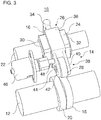
- Figur 3
- eine weitere perspektivische Ansicht des variablen Ventiltriebs gemäß der ersten Ausführungsform mit Aktorvorrichtung;
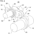
- Figur 4
- eine perspektivische Ansicht eines variablen Ventiltriebs gemäß einer zweiten Ausführungsform; und
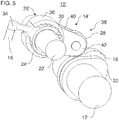
- Figur 5
- eine weitere perspektivische Ansicht des variablen Ventiltriebs gemäß der zweiten Ausführungsform.
- Die in den Figuren gezeigten Ausführungsformen stimmen zumindest teilweise überein, so dass ähnliche oder identische Teile mit den gleichen Bezugszeichen versehen sind und zu deren Erläuterung auch auf die Beschreibung der anderen Ausführungsformen bzw. Figuren verwiesen wird, um Wiederholungen zu vermeiden.
- Die
Figuren 1 und2 zeigen einen variablen Ventiltrieb 10 in unterschiedlichen Ansichten. Der variable Ventiltrieb 10 weist eine Nockenwelle 12, einen Übertragungshebel 14 und ein Hubventil 16 (nur abschnittsweise mit gestrichelten Linien inFigur 1 und2 angedeutet) auf. Das Hubventil ist insbesondere ein Ladungswechselventil, zum Beispiel ein Einlassventil oder ein Auslassventil, eines Zylinders eines Verbrennungsmotors. - Die Nockenwelle 12 kann als eine obenliegende oder eine untenliegende Nockenwelle ausgebildet sein. Die Nockenwelle 12 weist einen ersten Nocken 18 und einen zweiten Nocken 20 auf. Der ersten Nocken 18 ist in einer Längsrichtung der Nockenwelle 12 neben dem zweiten Nocken 20 angeordnet. Der erste Nocken 18 grenzt an den zweiten Nocken 20. In anderen Ausführungsformen können die Nocken 18 und 20 in einer Längsrichtung der Nockenwelle 12 voneinander beabstandet sein.
- Die Nocken 18 und 20 sind dazu ausgebildet, dass Hubventil 16 unterschiedlich zu betätigen. Die Nocken 18, 20 sind in einer Umfangsrichtung um eine Längsachse der Nockenwelle 12 versetzt angeordnet. Zusätzlich oder alternativ könnten die Nocken 18, 20 unterschiedliche Nockenkonturen aufweisen, zum Beispiel unterschiedliche hohe und/oder breite Erhebungen aufweisen.
- Der Übertragungshebel 14 ist in Wirkverbindung zwischen der Nockenwelle 12 und dem Hubventil 16 angeordnet. Im Einzelnen kann der Übertragungshebel 14 wahlweise eine Wirkverbindung zwischen dem ersten Nocken 18 und dem Hubventil 16 oder zwischen dem zweiten Nocken 20 und dem Hubventil 16 herstellen. In einigen Ausführungsformen kann der Übertragungshebel 14 mit mehreren Hubventilen in Wirkverbindung stehen.
- Der Übertragungshebel 14 weist eine Schwenkachse 22, ein Trägerbauteil 24, eine Halterung 26 und einen Nockenfolger 28 auf.
- Das Trägerbauteil 24 ist schwenkbar auf der Schwenkachse 22 angeordnet. Die Schwenkachse 22 kann bspw. in einem Zylinderkopf befestigt sein. Im Einzelnen weist das Trägerbauteil 24 eine Achsbohrung für die Schwenkachse 22 auf. Das Trägerbauteil 24 ist um eine Längsachse der Schwenkachse 22 schwenkbar. Das Trägerbauteil 24 ist axial auf der Schwenkachse 22 festgelegt, zum Beispiel durch die dargestellten Sicherungsringe 30, 32. In einer Ausführungsform kann eines der Sicherungsbauteile auch als ein Anschlag für die verschiebbare Halterung 26 dienen.
- Das Trägerbauteil 24 weist einen Betätigungsabschnitt 34 auf, der direkt oder indirekt mit dem Abschnitt des Ladungswechselventils 16 in Wirkverbindung steht. Alternativ könnte beispielsweise die Halterung 26 den Betätigungsabschnitt 34 aufweisen.
- Es ist auch möglich, dass der Betätigungsabschnitt bspw. über ein Brücke mit mehreren Ladungswechselventilen in Wirkverbindung steht.
- In der gezeigten Ausführungsform weist das Trägerbauteil 24 eine rechteckige Grundform mit angefasten Kanten auf. Insbesondere weist das Trägerbauteil 24 in einer Ebene senkrecht zur Längsachse der Schwenkachse 22 eine rechteckige Außenkontur mit angefasten Ecken auf.
- Die Halterung 26 weist einen Führungsbereich 36 und einen Gabelbereich 38 auf. Der Gabelbereich 38 ist an dem Führungsbereich 36 befestigt, zum Beispiel geschweißt. Der Führungsbereich 36 weist einen U-förmigen Querschnitt in einer Ebene senkrecht zur Längsrichtung der Schwenkachse 22 auf. Der Führungsbereich 36 umgreift das Trägerbauteil 24 teilweise. Der Führungsbereich 36 und das Trägerbauteil 24 sind so angepasst, dass der Führungsbereich 36 auf dem Trägerbauteil 24 verschiebbar ist. Der Führungsbereich 36 ist auf dem Trägerbauteil 24 in einer Richtung parallel zur Schwenkachse 22 und zur Nockenwelle 12 verschiebbar.
- In anderen Ausführungsformen kann die Halterung für den Nockenfolger beispielsweise direkt auf der Schwenkachse 22 angebracht sein. Mit anderen Worten gesagt, das Trägerbauteil kann entfallen. Die Halterung ist dann axial verschiebbar mit der Schwenkachse 22 verbunden. Die Halterung ist zudem drehbar mit der Schwenkachse 22 verbunden. Die Halterung weist beispielsweise eine kreisrunde Achsbohrung für die Schwenkachse 22 auf.
- Die Halterung 26 hält den Nockenfolger 28. Im Einzelnen weist die Halterung 26 den Gabelbereich 38 auf. Der Gabelbereich 38 weist zwei gegenüberliegende Vorsprünge oder Flanken 40, 42 auf. Die Vorsprünge 40, 42 erstrecken sich von dem Führungsbereich 36. Zwischen den Vorsprüngen 40, 42 erstreckt sich eine Drehachse 44. Auf der Drehachse 44 ist der Nockenfolger 28 angeordnet. In der vorliegenden Ausführungsform ist der Nockenfolger 28 als eine Rolle ausgebildet. Allerdings kann der Nockenfolger 28 auch eine andere Form aufweisen.
- Der Nockenfolger 28 ist dazu ausgebildet, einer Nockenkontur eines Nockens während einer Drehung der Nockenwelle 12 zu folgen. Dabei bewirkt die Nockenkontur ein Schwenken des Übertragungshebels 14 um die Schwenkachse 22 zum Betätigen des Hubventils 16.
- Der Nockenfolger 28 und der Betätigungsabschnitt 34 sind auf gegenüberliegenden Seiten bezüglich der Schwenkachse 22 angeordnet. Mit anderen Worten gesagt, der Übertragungshebel 14 ist als ein Kipphebel ausgebildet. In anderen Ausführungsformen können der Nockenfolger 28 und der Betätigungsabschnitt 34 auf der gleichen Seite bezüglich der Schwenkachse 22 angeordnet sein. D. h., der Übertragungshebel kann beispielsweise auch als ein Schlepphebel ausgebildet sein.
- Der Nockenfolger 28 kann wahlweise einer Nockenkontur des ersten Nockens 18 (wie in
Figur 1 und2 dargestellt) oder einer Nockenkontur des zweiten Nockens 20 folgen. Dazu kann die Halterung 26 zwischen einer ersten Axialposition und einer zweiten Axialposition verschoben werden. In der ersten Axialposition hält die Halterung 26 den Nockenfolger 28 so, dass der Nockenfolger 28 der Nockenkontur des ersten Nockens 18 folgt. In der zweiten Axialposition folgt der Nockenfolger 28 der Nockenkontur des zweiten Nockens 20. Die erste und zweite Axialposition können beispielsweise durch Anschläge für die Halterung 26 definiert sein. - Dies ermöglicht, dass unterschiedliche Nockenkonturen zum Betätigen des Hubventils 16 verwendet werden können. So können verschiedene Steuerzeiten für ein oder mehrere Hubventile 16 beispielsweise in Abhängigkeit einer Last realisiert werden. Denkbar ist beispielsweise eine Umschaltung zwischen Normalsteuerzeiten und Miller-Steuerzeiten für ein oder mehrere Einlassventile. Die Normalsteuerzeiten entsprechen bspw. den Steuerzeiten für einen Otto- oder Dieselkreisprozess. Ein Auslassventil kann beispielsweise zwischen einem Normalbetrieb mit einer Öffnung des Auslassventils im Ausschubtakt und einem Motorbremsbetrieb umgeschaltet werden. Im Motorbremsbetrieb wird beispielsweise kein Kraftstoff eingespritzt und das Auslassventil beispielsweise zum Ende des Verdichtungstaktes und/oder zum Ende des Ausschubtaktes geöffnet, sodass eine negative Arbeit vom entsprechenden Zylinder verrichtet wird, der die Kurbelwelle bremst.
- In einigen Ausführungsformen kann die Halterung 26 zusätzlich so verschoben werden, dass der Nockenfolger 28 einer Nockenkontur eines weiteren Nockens der Nockenwelle 12 folgt. Dazu kann die Nockenwelle 12 mindestens einen weiteren Nocken aufweisen. Der mindestens eine weitere Nocken ist in einer Längsrichtung der Nockenwelle 12 versetzt zu dem ersten Nocken 18 und dem zweiten Nocken 20 angeordnet ist. Eine Nockenkontur jedes weiteren Nockens unterscheidet sich von einer Nockenkontur des zweiten Nockens 20 und einer Nockenkontur des ersten Nockens 18. Alternativ können die Nocken in einer Umfangsrichtung um eine Längsachse der Nockenwelle 12 versetzt angeordnet sein. Die Nocken können beispielsweise direkt aneinandergrenzen.
- Zum Verschieben der Halterung 26 ist eine Aktorvorrichtung vorgesehen. Die Aktorvorrichtung ist dazu ausgebildet, die Halterung 26 parallel zur Schwenkachse 22 und zur Nockenwelle 12 axial zu verschieben. Im Einzelnen ist die Aktorvorrichtung dazu ausgebildet, die Halterung 26 mindestens zwischen der ersten Axialposition und der zweiten Axialposition zu verschieben. In der ersten Axialposition (gezeigt in den
Figuren 1 und2 ) ist der Nockenfolger 28 in Kontakt mit der Nockenkontur des ersten Nockens 18. In der zweiten Axialposition ist der Nockenfolger 28 in Kontakt mit der Nockenkontur des zweiten Nockens 20. - Die Aktorvorrichtung kann beispielsweise als eine pneumatische, hydraulische, elektromechanische und/oder elektromagnetische Aktorvorrichtung ausgebildet sein. Im Falle einer hydraulischen Aktorvorrichtung können beispielsweise ein Stellzylinder, ein System mit Federn und/oder zwei mit Hydraulikflüssigkeit befüllbare Kammern usw. verwendet werden.
- In einigen Ausführungsformen kann die Aktorvorrichtung die Halterung 26 in nur einer Richtung axial verschieben, wobei eine Rückstellung mit elastischen Elementen, z. B. einer Feder, realisierbar ist. Alternativ kann die Aktorvorrichtung die Halterung 26 in einer ersten Richtung und einer zweiten, entgegengesetzten Richtung axial verschieben.
- Die Aktorvorrichtung kann direkt oder indirekt, zum Beispiel über ein Gestänge, mit der Halterung 26 verbunden sein. In einigen Ausführungsformen kann die Aktorvorrichtung zumindest teilweise in dem Übertragungshebel 14 integriert oder extern von dem Übertragungshebel 14 angeordnet sein. Die Aktorvorrichtung kann insbesondere so ausgebildet sein oder angesteuert werden, dass die Halterung 26 und somit der Nockenfolger 28 nur zwischen einem Grundkreis des ersten Nockens 18 und einem Grundkreis des zweiten Nockens 20 verschoben wird.
- In der
Figur 3 ist eine beispielhafte Aktorvorrichtung 46 dargestellt. Die Aktorvorrichtung 46 ist ortsfest an einem geeigneten Bauteil befestigt (nicht dargestellt). Die Aktorvorrichtung 46 weist einen bewegbaren Stift 48 auf, der an einer Fläche des Vorsprungs 42 angreift. Wie inFigur 3 dargestellt ist, bewirkt ein Ausfahren des Stifts 48 eine Verschiebung der Halterung 26, sodass der Nockenfolger 28 der Nockenkontur des ersten Nockens 18 folgt. Mit anderen Worten gesagt, bewirkt ein Ausfahren des Stifts 28 eine Verschiebung der Halterung 26 in die erste Axialposition. Damit der Nockenfolger 28 einer Nockenkontur des zweiten Nockens 20 folgt, ist eine Rückstellung erforderlich. Die Rückstellung kann beispielsweise über einen weiteren Aktor (nicht dargestellt) der Aktorvorrichtung 46 erfolgen. Der weitere Aktor kann beispielsweise an einer gegenüberliegenden Seite des Gabelbereichs 38 angreifen. Ebenso ist eine Rückstellung über elastische Elemente (nicht dargestellt) möglich. - Die
Figuren 4 und5 zeigen eine weitere Ausführungsform des variablen Ventiltriebs. Der variable Ventiltrieb 10' derFiguren 4 und5 ist ähnlich zu dem variablen Ventiltrieb 10 derFiguren 1 und2 ausgebildet. Im Unterschied zu dem variablen Ventiltriebs 10 derFiguren 1 und2 weist der variable Ventiltriebs 10' insbesondere ein modifiziertes Trägerbauteil 24' und eine modifizierte Halterung 26' auf. - Das Trägerbauteil 24' weist eine Außenprofilierung in Form einer Verzahnung auf. Die Außenprofilierung des Trägerbauteils 24' ist in Eingriff mit einer entsprechenden Innenprofilierung der Führung 36' der Halterung 26'. Die Führung 36' der Halterung 26' umgreift das Trägerbauteil 24' teilweise. Die Führung 36' weist einen Bogensegmentquerschnitt in einer Querschnittebene senkrecht zur Schwenkachse 22 auf. Die ineinandergreifenden Profilierungen des Trägerbauteils 24' und der Halterung 26' ermöglichen eine Axialverschiebung der Halterung 26' auf dem Trägerbauteil 24'. Die ineinandergreifenden Profilierungen verbinden die Haltung 26' zudem drehfest mit dem Trägerbauteil 24' um die Schwenkachse 22.
- Allgemein gesagt kann das Trägerbauteil in einer Querschnittsebene senkrecht zu einer Längsrichtung der Schwenkachse 22 eine zur Schwenkachse 22 rotationsasymmetrische Außenkontur aufweisen. Die Halterung kann eine entsprechende rotationsasymmetrische Innenkontur aufweisen. Dies ermöglicht eine Axialverschiebung der Halterung relativ zum Trägerbauteil und verbindet die Halterung gleichzeitig drehfest mit dem Trägerbauteil.
- Die Erfindung ist nicht auf die vorstehend beschriebenen bevorzugten Ausführungsbeispiele beschränkt. Vielmehr ist eine Vielzahl von Varianten und Abwandlungen möglich, die ebenfalls von dem Erfindungsgedanken Gebrauch machen und deshalb in den Schutzbereich fallen. Insbesondere beansprucht die Erfindung auch Schutz für den Gegenstand und die Merkmale der Unteransprüche unabhängig von den in Bezug genommenen Ansprüchen.
-
- 10
- Variabler Ventiltrieb
- 12
- Nockenwelle
- 14
- Übertragungshebel (Kipphebel)
- 16
- Hubventil (Ladungswechselventil)
- 18
- Erster Nocken
- 20
- Zweiter Nocken
- 22
- Schwenkachse
- 24
- Trägerbauteil
- 26
- Halterung
- 28
- Nockenfolger (Rolle)
- 30
- Erster Sicherungsring
- 32
- Zweiter Sicherungsring
- 34
- Betätigungsabschnitt
- 36
- Führungsbereich
- 38
- Gabelbereich
- 40
- Erster Vorsprung
- 42
- Zweiter Vorsprung
- 44
- Drehachse
- 46
- Aktorvorrichtung
- 48
- Stift
Claims (15)
- Variabler Ventiltrieb (10) für einen Verbrennungsmotor, aufweisend:mindestens ein Hubventil (16), insbesondere ein Ladungswechselventil;eine Nockenwelle (12), die einen ersten Nocken (18) und einen in einer Längsrichtung der Nockenwelle (12) versetzt angeordneten zweiten Nocken (20) aufweist, wobei sich eine Nockenkontur des ersten Nockens (18) von einer Nockenkontur des zweiten Nockens (20) unterscheidet und/oder der erste Nocken (18) und der zweiten Nocken (20) in einer Umfangsrichtung um eine Längsachse der Nockenwelle (12) versetzt angeordnet sind; undeinen Übertragungshebel (14), der in Wirkverbindung zwischen dem mindestens einen Hubventil (16) und der Nockenwelle (12) zum Betätigen des mindestens einen Hubventils (16) angeordnet ist, wobei:der Übertragungshebel (14) eine Schwenkachse (22), eine Halterung (26) und einen Nockenfolger (28) aufweist;die Halterung (26) schwenkbar um die Schwenkachse (22) gelagert ist;die Halterung (26) den Nockenfolger (28) hält; unddie Halterung (26) parallel zur Schwenkachse (22) und/oder parallel zur Nockenwelle (12) axial verschiebbar gelagert ist, sodass der Nockenfolger (28) wahlweise der Nockenkontur des ersten Nockens (18) oder der Nockenkontur des zweiten Nockens (20) folgt.
- Variabler Ventiltrieb (10) nach Anspruch 1, wobei:die Halterung (26) direkt auf der Schwenkachse (22) schwenkbar und axial verschiebbar gelagert ist; oderder Übertragungshebel (14) ferner ein Trägerbauteil (24) aufweist, das schwenkbar um die Schwenkachse (22) gelagert ist und die Halterung (26) axial verschiebbar lagert.
- Variabler Ventiltrieb (10) nach Anspruch 1 oder Anspruch 2, wobei:das Trägerbauteil (24) oder die Halterung (26) eine Achsbohrung für die Schwenkachse (22) aufweist; und/oderdas Trägerbauteil (24) mit der Halterung (26) drehfest um die Schwenkachse (22) verbunden ist, insbesondere über einen Formschluss zwischen der Halterung (26) und dem Trägerbauteil (24).
- Variabler Ventiltrieb (10) nach Anspruch 2 oder Anspruch 3, wobei:das Trägerbauteil (24) in einer Querschnittsebene senkrecht zu einer Längsrichtung der Schwenkachse (22) eine zur Schwenkachse (22) rotationsasymmetrische Außenkontur aufweist; und/oderdie Halterung (26) in einer Querschnittsebene senkrecht zu einer Längsrichtung der Schwenkachse (22) eine zur Schwenkachse (22) rotationsasymmetrische Innenkontur aufweist.
- Variabler Ventiltrieb (10) nach Anspruch 4, wobei:die Außenkontur und/oder die Innenkontur eine Profilierung, vorzugsweise ein Keilprofil oder Zahnprofil, aufweist; und/oderdie Außenkontur und/oder die Innenkontur insbesondere eine Mehreckform, zum Beispiel eine Rechteckform, aufweist.
- Variabler Ventiltrieb (10) nach einem der Ansprüche 2 bis 5, wobei das Trägerbauteil (24) auf der Schwenkachse (22) axial gesichert ist, zum Beispiel durch einen auf der Schwenkachse (22) gesicherten Sicherungsring (30, 32) oder eine Passfeder.
- Variabler Ventiltrieb (10) nach einem der vorherigen Ansprüche, wobei die Halterung (26) und/oder das Trägerbauteil (24) einen Betätigungsabschnitt (34) zum Betätigen des mindestens einen Hubventils (16) aufweist.
- Variabler Ventiltrieb (10) nach einem der vorherigen Ansprüche, wobei:die Halterung (26) einen Gabelbereich (38) mit zwei gegenüberliegenden Vorsprüngen (40, 42) aufweist, wobei sich zwischen den Vorsprüngen (40, 42) insbesondere eine Drehachse (44) erstreckt, auf der der Nockenfolger (28) drehbar gelagert ist, und/oderder Nockenfolger (28) als eine Rolle ausgebildet ist, die von der Halterung (26) insbesondere drehbar gelagert ist.
- Variabler Ventiltrieb (10) nach einem der vorherigen Ansprüche, ferner aufweisend eine Aktorvorrichtung (46), die dazu ausgebildet ist, die Halterung (26) parallel zur Schwenkachse (22) und/oder zur Nockenwelle (12) axial zu verschieben.
- Variabler Ventiltrieb (10) nach Anspruch 9, wobei:die Aktorvorrichtung (46) als eine pneumatische, hydraulische, elektromechanische und/oder elektromagnetische Aktorvorrichtung (46) ausgebildet ist; und/oderdie Aktorvorrichtung (46) direkt oder indirekt, zum Beispiel über ein Gestänge, mit der Halterung (26) verbunden ist; und/oderdie Aktorvorrichtung (46) zumindest teilweise in dem Übertragungshebel (14) integriert oder extern von dem Übertragungshebel (14) angeordnet ist.
- Variabler Ventiltrieb (10) nach Anspruch 9 oder Anspruch 10, wobei:die Aktorvorrichtung (46) zum Verschieben der Halterung (26) an einer Seitenfläche der Halterung (26), die sich senkrecht zu einer Längsrichtung der Schwenkachse (22) erstreckt, angreift, insbesondere an einem Vorsprung (40, 42) eines Gabelbereichs (38) der Halterung (26); und/oderdie Aktorvorrichtung (46) so ausgebildet ist und/oder angesteuert wird, dass der Nockenfolger (28) nur zwischen einem Grundkreis des ersten Nockens (18) und einem Grundkreis des zweiten Nockens (20) verschoben wird.
- Variabler Ventiltrieb (10) nach einem der vorherigen Ansprüche, wobei:die Nockenwelle (12) mindestens einen weiteren Nocken aufweist, der in einer Längsrichtung der Nockenwelle (12) versetzt zu dem ersten Nocken (18) und dem zweiten Nocken (20) angeordnet ist, wobei eine Nockenkontur jedes weiteren Nockens sich von einer Nockenkontur des ersten Nockens (18) und einer Nockenkontur des zweiten Nockens (20) unterscheidet und/oder jeder weitere Nocken in einer Umfangsrichtung um eine Längsachse der Nockenwelle (12) versetzt zu dem ersten Nocken (18) und dem zweiten Nocken (20) angeordnet ist; undder Nockenfolger (28) durch eine Verschiebung der Halterung (26) zusätzlich wahlweise der Nockenkontur jedes weiteren Nockens folgt.
- Variabler Ventiltrieb (10) nach einem der vorherigen Ansprüche, wobei der Übertragungshebel (14) als ein Schlepphebel oder ein Kipphebel ausgebildet ist.
- Variabler Ventiltrieb (10) nach einem der vorherigen Ansprüche, wobei:das mindestens eine Hubventil (16) ein Einlassventil des Verbrennungsmotors ist und der erste Nocken (18) einen Normalbetrieb bewirkt und/oder der zweite Nocken (20) einen Millerbetrieb, einen Atkinsonbetrieb, einen Thermomanagementbetrieb, einen Dekompressionsbetrieb oder eine Zylinderabschaltung bewirkt; oderdas mindestens eine Hubventil (16) ein Auslassventil des Verbrennungsmotors ist und der erste Nocken (18) einen Normalbetrieb bewirkt und/oder der zweite Nocken (20) einen Motorbremsbetrieb, einen Thermomanagementbetrieb, einen Dekompressionsbetrieb oder eine Zylinderabschaltung bewirkt.
- Kraftfahrzeug, insbesondere Nutzfahrzeug, mit einem variablen Ventiltrieb (10) nach einem der vorherigen Ansprüche.
Applications Claiming Priority (1)
| Application Number | Priority Date | Filing Date | Title |
|---|---|---|---|
| DE102017003439.7A DE102017003439A1 (de) | 2017-04-08 | 2017-04-08 | Variabler Ventiltrieb |
Publications (2)
| Publication Number | Publication Date |
|---|---|
| EP3385513A1 true EP3385513A1 (de) | 2018-10-10 |
| EP3385513B1 EP3385513B1 (de) | 2020-06-03 |
Family
ID=61868458
Family Applications (1)
| Application Number | Title | Priority Date | Filing Date |
|---|---|---|---|
| EP18165461.7A Active EP3385513B1 (de) | 2017-04-08 | 2018-04-03 | Variabler ventiltrieb |
Country Status (6)
| Country | Link |
|---|---|
| US (1) | US10584619B2 (de) |
| EP (1) | EP3385513B1 (de) |
| CN (1) | CN108729969B (de) |
| BR (1) | BR102018006840B1 (de) |
| DE (1) | DE102017003439A1 (de) |
| RU (1) | RU2770809C2 (de) |
Cited By (1)
| Publication number | Priority date | Publication date | Assignee | Title |
|---|---|---|---|---|
| WO2022152581A1 (en) * | 2021-01-15 | 2022-07-21 | Eaton Intelligent Power Limited | Roller shifter, shift bar assembly, shift roller assembly, and shift roller for variable valve actuation in a valvetrain |
Families Citing this family (4)
| Publication number | Priority date | Publication date | Assignee | Title |
|---|---|---|---|---|
| DE102018205730A1 (de) * | 2018-04-16 | 2019-10-17 | Mahle International Gmbh | Kipphebelanordnung und ein Ventiltrieb |
| DE102018132857A1 (de) * | 2018-12-19 | 2020-06-25 | Man Truck & Bus Se | Schaltbare Betätigungsvorrichtung für ein Hubventil einer Brennkraftmaschine, Brennkraftmaschine und Kraftfahrzeug |
| CN109440253A (zh) * | 2018-12-31 | 2019-03-08 | 江苏莱纳多智能装备有限公司 | 一种凸轮开口提花机的传动机构 |
| CN110405405B (zh) * | 2019-07-09 | 2021-07-13 | 深圳市圣地保人防有限公司 | 连杆自动焊机 |
Citations (7)
| Publication number | Priority date | Publication date | Assignee | Title |
|---|---|---|---|---|
| DE3346556A1 (de) * | 1982-12-23 | 1984-07-05 | Nissan Motor Co., Ltd., Yokohama, Kanagawa | Ventilsteuerwechselvorrichtung fuer brennkraftmaschinen |
| JPS61129411A (ja) * | 1984-11-27 | 1986-06-17 | Taiji Yamada | エンジンのバルブ動作可変機構 |
| JPS61155605U (de) * | 1985-03-19 | 1986-09-26 | ||
| JP2005155555A (ja) * | 2003-11-27 | 2005-06-16 | Nippon Piston Ring Co Ltd | 可変動弁機構 |
| AT511050A1 (de) * | 2011-01-27 | 2012-08-15 | Avl List Gmbh | Brennkraftmaschine mit einer variablen ventilbetätigungseinrichtung |
| WO2015185046A1 (de) * | 2014-06-05 | 2015-12-10 | Schaeffler Technologies AG & Co. KG | Variabler ventiltrieb für eine zylindereinheit einer hubkolbenbrennkraftmaschine |
| WO2016059456A1 (en) * | 2014-10-15 | 2016-04-21 | Shanghai Universoon Auto Parts Co., Ltd. | Engine braking method and system |
Family Cites Families (13)
| Publication number | Priority date | Publication date | Assignee | Title |
|---|---|---|---|---|
| DE3315396A1 (de) * | 1983-04-28 | 1984-10-31 | Nissan Motor Co., Ltd., Yokohama, Kanagawa | Mehrzylinder-brennkraftmaschine |
| JPH0639892B2 (ja) * | 1985-02-12 | 1994-05-25 | スズキ株式会社 | 4サイクルエンジンのバルブタイミング可変装置 |
| JPH06123209A (ja) * | 1992-10-09 | 1994-05-06 | Nissan Motor Co Ltd | エンジンの弁作動装置 |
| CN100436760C (zh) * | 2005-08-15 | 2008-11-26 | 本田技研工业株式会社 | 内燃机的可变气门传动装置 |
| DE102010011828A1 (de) * | 2010-03-18 | 2011-09-22 | Schaeffler Technologies Gmbh & Co. Kg | Schaltbarer Hebel für einen Ventiltrieb einer Brennkraftmaschine |
| DE102011106395A1 (de) * | 2011-07-02 | 2013-01-03 | Man Truck & Bus Ag | Ventilsteuerung für mindestens ein Ventil einer Brennkraftmaschine |
| RU2529982C2 (ru) * | 2013-01-24 | 2014-10-10 | Федеральное государственное унитарное предприятие "Центральный ордена Трудового Красного Знамени научно-исследовательский автомобильный и автомоторный институт "НАМИ" | Устройство привода клапана двигателя |
| JP5928835B2 (ja) * | 2013-07-03 | 2016-06-01 | 株式会社デンソー | バルブリフト調整装置 |
| DE102015215123A1 (de) * | 2015-08-07 | 2017-02-09 | Mahle International Gmbh | Ventiltrieb für eine Brennkraftmaschine |
| DE202015009047U1 (de) * | 2015-08-07 | 2016-08-03 | Mahle International Gmbh | Ventiltrieb für eine Brennkraftmaschine |
| DE102017205538A1 (de) * | 2017-03-31 | 2018-10-04 | Mahle International Gmbh | Ventiltrieb für eine Brennkraftmaschine |
| DE102017205571A1 (de) * | 2017-03-31 | 2018-10-04 | Mahle International Gmbh | Ventiltrieb für eine Brennkraftmaschine |
| DE102017205540A1 (de) * | 2017-03-31 | 2018-10-04 | Mahle International Gmbh | Ventiltrieb für eine Brennkraftmaschine |
-
2017
- 2017-04-08 DE DE102017003439.7A patent/DE102017003439A1/de not_active Withdrawn
-
2018
- 2018-04-03 EP EP18165461.7A patent/EP3385513B1/de active Active
- 2018-04-04 US US15/945,485 patent/US10584619B2/en active Active
- 2018-04-04 BR BR102018006840-7A patent/BR102018006840B1/pt active IP Right Grant
- 2018-04-06 RU RU2018112469A patent/RU2770809C2/ru active
- 2018-04-08 CN CN201810307226.4A patent/CN108729969B/zh active Active
Patent Citations (7)
| Publication number | Priority date | Publication date | Assignee | Title |
|---|---|---|---|---|
| DE3346556A1 (de) * | 1982-12-23 | 1984-07-05 | Nissan Motor Co., Ltd., Yokohama, Kanagawa | Ventilsteuerwechselvorrichtung fuer brennkraftmaschinen |
| JPS61129411A (ja) * | 1984-11-27 | 1986-06-17 | Taiji Yamada | エンジンのバルブ動作可変機構 |
| JPS61155605U (de) * | 1985-03-19 | 1986-09-26 | ||
| JP2005155555A (ja) * | 2003-11-27 | 2005-06-16 | Nippon Piston Ring Co Ltd | 可変動弁機構 |
| AT511050A1 (de) * | 2011-01-27 | 2012-08-15 | Avl List Gmbh | Brennkraftmaschine mit einer variablen ventilbetätigungseinrichtung |
| WO2015185046A1 (de) * | 2014-06-05 | 2015-12-10 | Schaeffler Technologies AG & Co. KG | Variabler ventiltrieb für eine zylindereinheit einer hubkolbenbrennkraftmaschine |
| WO2016059456A1 (en) * | 2014-10-15 | 2016-04-21 | Shanghai Universoon Auto Parts Co., Ltd. | Engine braking method and system |
Cited By (1)
| Publication number | Priority date | Publication date | Assignee | Title |
|---|---|---|---|---|
| WO2022152581A1 (en) * | 2021-01-15 | 2022-07-21 | Eaton Intelligent Power Limited | Roller shifter, shift bar assembly, shift roller assembly, and shift roller for variable valve actuation in a valvetrain |
Also Published As
| Publication number | Publication date |
|---|---|
| BR102018006840B1 (pt) | 2023-05-16 |
| RU2018112469A3 (de) | 2021-08-20 |
| US10584619B2 (en) | 2020-03-10 |
| CN108729969A (zh) | 2018-11-02 |
| EP3385513B1 (de) | 2020-06-03 |
| RU2018112469A (ru) | 2019-10-08 |
| US20180291776A1 (en) | 2018-10-11 |
| RU2770809C2 (ru) | 2022-04-21 |
| BR102018006840A2 (pt) | 2018-12-18 |
| CN108729969B (zh) | 2021-10-26 |
| DE102017003439A1 (de) | 2018-10-11 |
Similar Documents
| Publication | Publication Date | Title |
|---|---|---|
| EP3385513A1 (de) | Variabler ventiltrieb | |
| EP3170997B1 (de) | Variabler ventiltrieb mit einem kipphebel | |
| DE19520117C2 (de) | Ventiltrieb einer Brennkraftmaschine | |
| DE10220904B4 (de) | Vorrichtung zum Verstellen des Hubs eines von einer Nockenwelle betätigten Ventils | |
| DE19815112B4 (de) | Anordnung zur variablen Ventilzeitsteuerung und Ventilbetätigung | |
| WO1995002116A1 (de) | Verfahren und vorrichtung zur variablen steuerung eines ventils einer brennkraftmaschine | |
| EP2132418A1 (de) | Ventiltrieb für gaswechselventile einer brennkraftmaschine mit verschiebbarem nockenträger und doppelschneckentrieb | |
| EP3947927A1 (de) | Schiebenockensystem und motor | |
| DE102013019000A1 (de) | Motorbremsvorrichtung für eine Brennkraftmaschine | |
| DE102007010150A1 (de) | Ventiltrieb für Gaswechselventile einer Brennkraftmaschine mit Nockenträgerarretierung von außen | |
| DE19908286A1 (de) | Variable Ventilsteuerung für Brennkraftmaschinen | |
| EP3421741A1 (de) | Variabler ventiltrieb | |
| DE102010025099A1 (de) | Nockenwelle | |
| WO2012175070A1 (de) | Schlepphebel und verbrennungsmotor mit einem solchen | |
| AT519812B1 (de) | Mechanische Ventilbetätigungsvorrichtung | |
| DE102011116117A1 (de) | Ventiltriebvorrichtung für eine Brennkraftmaschine | |
| DE102013005803A1 (de) | Ventiltriebvorrichtung für eine Brennkraftmaschine | |
| DE102017205814A1 (de) | Mechanische Ventilbetätigungsvorrichtung | |
| EP2716882B1 (de) | Mechanisch steuerbarer Ventiltrieb für eine Hubkolbenmaschine | |
| DE102020123950A1 (de) | Schlepphebelvorrichtung und Aktuator | |
| DE102011122451A1 (de) | Ventiltrieb für eine Brennkraftmaschine | |
| WO2020108933A1 (de) | Hubvariabler ventiltrieb mit wenigstens zwei arbeitslagen | |
| DE102011116439A1 (de) | Ventiltriebvorrichtung mit vollvariabler Ventilhubumstellung für eine Brennkraftmaschine | |
| EP0679798B1 (de) | Einrichtung zur gleichzeitigen Betätigung zweier Gaswechselventile einer Brennkraftmaschine | |
| DE102006022481A1 (de) | Zylinderkopf für eine Brennkraftmaschine mit einem hubvariablen Ventiltrieb |
Legal Events
| Date | Code | Title | Description |
|---|---|---|---|
| PUAI | Public reference made under article 153(3) epc to a published international application that has entered the european phase |
Free format text: ORIGINAL CODE: 0009012 |
|
| STAA | Information on the status of an ep patent application or granted ep patent |
Free format text: STATUS: THE APPLICATION HAS BEEN PUBLISHED |
|
| AK | Designated contracting states |
Kind code of ref document: A1 Designated state(s): AL AT BE BG CH CY CZ DE DK EE ES FI FR GB GR HR HU IE IS IT LI LT LU LV MC MK MT NL NO PL PT RO RS SE SI SK SM TR |
|
| AX | Request for extension of the european patent |
Extension state: BA ME |
|
| STAA | Information on the status of an ep patent application or granted ep patent |
Free format text: STATUS: REQUEST FOR EXAMINATION WAS MADE |
|
| 17P | Request for examination filed |
Effective date: 20190408 |
|
| RBV | Designated contracting states (corrected) |
Designated state(s): AL AT BE BG CH CY CZ DE DK EE ES FI FR GB GR HR HU IE IS IT LI LT LU LV MC MK MT NL NO PL PT RO RS SE SI SK SM TR |
|
| RAP1 | Party data changed (applicant data changed or rights of an application transferred) |
Owner name: MAN TRUCK & BUS SE |
|
| GRAP | Despatch of communication of intention to grant a patent |
Free format text: ORIGINAL CODE: EPIDOSNIGR1 |
|
| STAA | Information on the status of an ep patent application or granted ep patent |
Free format text: STATUS: GRANT OF PATENT IS INTENDED |
|
| INTG | Intention to grant announced |
Effective date: 20191202 |
|
| GRAS | Grant fee paid |
Free format text: ORIGINAL CODE: EPIDOSNIGR3 |
|
| GRAJ | Information related to disapproval of communication of intention to grant by the applicant or resumption of examination proceedings by the epo deleted |
Free format text: ORIGINAL CODE: EPIDOSDIGR1 |
|
| GRAL | Information related to payment of fee for publishing/printing deleted |
Free format text: ORIGINAL CODE: EPIDOSDIGR3 |
|
| STAA | Information on the status of an ep patent application or granted ep patent |
Free format text: STATUS: REQUEST FOR EXAMINATION WAS MADE |
|
| GRAR | Information related to intention to grant a patent recorded |
Free format text: ORIGINAL CODE: EPIDOSNIGR71 |
|
| STAA | Information on the status of an ep patent application or granted ep patent |
Free format text: STATUS: GRANT OF PATENT IS INTENDED |
|
| INTC | Intention to grant announced (deleted) | ||
| INTG | Intention to grant announced |
Effective date: 20200325 |
|
| GRAA | (expected) grant |
Free format text: ORIGINAL CODE: 0009210 |
|
| STAA | Information on the status of an ep patent application or granted ep patent |
Free format text: STATUS: THE PATENT HAS BEEN GRANTED |
|
| AK | Designated contracting states |
Kind code of ref document: B1 Designated state(s): AL AT BE BG CH CY CZ DE DK EE ES FI FR GB GR HR HU IE IS IT LI LT LU LV MC MK MT NL NO PL PT RO RS SE SI SK SM TR |
|
| REG | Reference to a national code |
Ref country code: GB Ref legal event code: FG4D Free format text: NOT ENGLISH |
|
| REG | Reference to a national code |
Ref country code: CH Ref legal event code: EP Ref country code: AT Ref legal event code: REF Ref document number: 1277230 Country of ref document: AT Kind code of ref document: T Effective date: 20200615 |
|
| REG | Reference to a national code |
Ref country code: DE Ref legal event code: R096 Ref document number: 502018001565 Country of ref document: DE |
|
| REG | Reference to a national code |
Ref country code: NL Ref legal event code: FP |
|
| REG | Reference to a national code |
Ref country code: SE Ref legal event code: TRGR |
|
| REG | Reference to a national code |
Ref country code: LT Ref legal event code: MG4D |
|
| PG25 | Lapsed in a contracting state [announced via postgrant information from national office to epo] |
Ref country code: LT Free format text: LAPSE BECAUSE OF FAILURE TO SUBMIT A TRANSLATION OF THE DESCRIPTION OR TO PAY THE FEE WITHIN THE PRESCRIBED TIME-LIMIT Effective date: 20200603 Ref country code: NO Free format text: LAPSE BECAUSE OF FAILURE TO SUBMIT A TRANSLATION OF THE DESCRIPTION OR TO PAY THE FEE WITHIN THE PRESCRIBED TIME-LIMIT Effective date: 20200903 Ref country code: GR Free format text: LAPSE BECAUSE OF FAILURE TO SUBMIT A TRANSLATION OF THE DESCRIPTION OR TO PAY THE FEE WITHIN THE PRESCRIBED TIME-LIMIT Effective date: 20200904 Ref country code: FI Free format text: LAPSE BECAUSE OF FAILURE TO SUBMIT A TRANSLATION OF THE DESCRIPTION OR TO PAY THE FEE WITHIN THE PRESCRIBED TIME-LIMIT Effective date: 20200603 |
|
| PG25 | Lapsed in a contracting state [announced via postgrant information from national office to epo] |
Ref country code: RS Free format text: LAPSE BECAUSE OF FAILURE TO SUBMIT A TRANSLATION OF THE DESCRIPTION OR TO PAY THE FEE WITHIN THE PRESCRIBED TIME-LIMIT Effective date: 20200603 Ref country code: HR Free format text: LAPSE BECAUSE OF FAILURE TO SUBMIT A TRANSLATION OF THE DESCRIPTION OR TO PAY THE FEE WITHIN THE PRESCRIBED TIME-LIMIT Effective date: 20200603 Ref country code: BG Free format text: LAPSE BECAUSE OF FAILURE TO SUBMIT A TRANSLATION OF THE DESCRIPTION OR TO PAY THE FEE WITHIN THE PRESCRIBED TIME-LIMIT Effective date: 20200903 Ref country code: LV Free format text: LAPSE BECAUSE OF FAILURE TO SUBMIT A TRANSLATION OF THE DESCRIPTION OR TO PAY THE FEE WITHIN THE PRESCRIBED TIME-LIMIT Effective date: 20200603 |
|
| PG25 | Lapsed in a contracting state [announced via postgrant information from national office to epo] |
Ref country code: AL Free format text: LAPSE BECAUSE OF FAILURE TO SUBMIT A TRANSLATION OF THE DESCRIPTION OR TO PAY THE FEE WITHIN THE PRESCRIBED TIME-LIMIT Effective date: 20200603 |
|
| PG25 | Lapsed in a contracting state [announced via postgrant information from national office to epo] |
Ref country code: SM Free format text: LAPSE BECAUSE OF FAILURE TO SUBMIT A TRANSLATION OF THE DESCRIPTION OR TO PAY THE FEE WITHIN THE PRESCRIBED TIME-LIMIT Effective date: 20200603 Ref country code: EE Free format text: LAPSE BECAUSE OF FAILURE TO SUBMIT A TRANSLATION OF THE DESCRIPTION OR TO PAY THE FEE WITHIN THE PRESCRIBED TIME-LIMIT Effective date: 20200603 Ref country code: RO Free format text: LAPSE BECAUSE OF FAILURE TO SUBMIT A TRANSLATION OF THE DESCRIPTION OR TO PAY THE FEE WITHIN THE PRESCRIBED TIME-LIMIT Effective date: 20200603 Ref country code: ES Free format text: LAPSE BECAUSE OF FAILURE TO SUBMIT A TRANSLATION OF THE DESCRIPTION OR TO PAY THE FEE WITHIN THE PRESCRIBED TIME-LIMIT Effective date: 20200603 Ref country code: CZ Free format text: LAPSE BECAUSE OF FAILURE TO SUBMIT A TRANSLATION OF THE DESCRIPTION OR TO PAY THE FEE WITHIN THE PRESCRIBED TIME-LIMIT Effective date: 20200603 Ref country code: PT Free format text: LAPSE BECAUSE OF FAILURE TO SUBMIT A TRANSLATION OF THE DESCRIPTION OR TO PAY THE FEE WITHIN THE PRESCRIBED TIME-LIMIT Effective date: 20201006 |
|
| PG25 | Lapsed in a contracting state [announced via postgrant information from national office to epo] |
Ref country code: PL Free format text: LAPSE BECAUSE OF FAILURE TO SUBMIT A TRANSLATION OF THE DESCRIPTION OR TO PAY THE FEE WITHIN THE PRESCRIBED TIME-LIMIT Effective date: 20200603 Ref country code: SK Free format text: LAPSE BECAUSE OF FAILURE TO SUBMIT A TRANSLATION OF THE DESCRIPTION OR TO PAY THE FEE WITHIN THE PRESCRIBED TIME-LIMIT Effective date: 20200603 Ref country code: IS Free format text: LAPSE BECAUSE OF FAILURE TO SUBMIT A TRANSLATION OF THE DESCRIPTION OR TO PAY THE FEE WITHIN THE PRESCRIBED TIME-LIMIT Effective date: 20201003 |
|
| REG | Reference to a national code |
Ref country code: DE Ref legal event code: R097 Ref document number: 502018001565 Country of ref document: DE |
|
| PLBE | No opposition filed within time limit |
Free format text: ORIGINAL CODE: 0009261 |
|
| STAA | Information on the status of an ep patent application or granted ep patent |
Free format text: STATUS: NO OPPOSITION FILED WITHIN TIME LIMIT |
|
| PG25 | Lapsed in a contracting state [announced via postgrant information from national office to epo] |
Ref country code: DK Free format text: LAPSE BECAUSE OF FAILURE TO SUBMIT A TRANSLATION OF THE DESCRIPTION OR TO PAY THE FEE WITHIN THE PRESCRIBED TIME-LIMIT Effective date: 20200603 |
|
| 26N | No opposition filed |
Effective date: 20210304 |
|
| PG25 | Lapsed in a contracting state [announced via postgrant information from national office to epo] |
Ref country code: SI Free format text: LAPSE BECAUSE OF FAILURE TO SUBMIT A TRANSLATION OF THE DESCRIPTION OR TO PAY THE FEE WITHIN THE PRESCRIBED TIME-LIMIT Effective date: 20200603 |
|
| PG25 | Lapsed in a contracting state [announced via postgrant information from national office to epo] |
Ref country code: MC Free format text: LAPSE BECAUSE OF FAILURE TO SUBMIT A TRANSLATION OF THE DESCRIPTION OR TO PAY THE FEE WITHIN THE PRESCRIBED TIME-LIMIT Effective date: 20200603 |
|
| PG25 | Lapsed in a contracting state [announced via postgrant information from national office to epo] |
Ref country code: LU Free format text: LAPSE BECAUSE OF NON-PAYMENT OF DUE FEES Effective date: 20210403 |
|
| REG | Reference to a national code |
Ref country code: BE Ref legal event code: MM Effective date: 20210430 |
|
| PG25 | Lapsed in a contracting state [announced via postgrant information from national office to epo] |
Ref country code: CH Free format text: LAPSE BECAUSE OF NON-PAYMENT OF DUE FEES Effective date: 20210430 Ref country code: LI Free format text: LAPSE BECAUSE OF NON-PAYMENT OF DUE FEES Effective date: 20210430 |
|
| PG25 | Lapsed in a contracting state [announced via postgrant information from national office to epo] |
Ref country code: IE Free format text: LAPSE BECAUSE OF NON-PAYMENT OF DUE FEES Effective date: 20210403 |
|
| PG25 | Lapsed in a contracting state [announced via postgrant information from national office to epo] |
Ref country code: IS Free format text: LAPSE BECAUSE OF FAILURE TO SUBMIT A TRANSLATION OF THE DESCRIPTION OR TO PAY THE FEE WITHIN THE PRESCRIBED TIME-LIMIT Effective date: 20201003 |
|
| PG25 | Lapsed in a contracting state [announced via postgrant information from national office to epo] |
Ref country code: BE Free format text: LAPSE BECAUSE OF NON-PAYMENT OF DUE FEES Effective date: 20210430 |
|
| GBPC | Gb: european patent ceased through non-payment of renewal fee |
Effective date: 20220403 |
|
| PG25 | Lapsed in a contracting state [announced via postgrant information from national office to epo] |
Ref country code: GB Free format text: LAPSE BECAUSE OF NON-PAYMENT OF DUE FEES Effective date: 20220403 |
|
| PGFP | Annual fee paid to national office [announced via postgrant information from national office to epo] |
Ref country code: SE Payment date: 20230317 Year of fee payment: 6 |
|
| PG25 | Lapsed in a contracting state [announced via postgrant information from national office to epo] |
Ref country code: CY Free format text: LAPSE BECAUSE OF FAILURE TO SUBMIT A TRANSLATION OF THE DESCRIPTION OR TO PAY THE FEE WITHIN THE PRESCRIBED TIME-LIMIT Effective date: 20200603 |
|
| PGFP | Annual fee paid to national office [announced via postgrant information from national office to epo] |
Ref country code: NL Payment date: 20230424 Year of fee payment: 6 |
|
| PG25 | Lapsed in a contracting state [announced via postgrant information from national office to epo] |
Ref country code: HU Free format text: LAPSE BECAUSE OF FAILURE TO SUBMIT A TRANSLATION OF THE DESCRIPTION OR TO PAY THE FEE WITHIN THE PRESCRIBED TIME-LIMIT; INVALID AB INITIO Effective date: 20180403 |
|
| PGFP | Annual fee paid to national office [announced via postgrant information from national office to epo] |
Ref country code: IT Payment date: 20230421 Year of fee payment: 6 Ref country code: FR Payment date: 20230421 Year of fee payment: 6 Ref country code: DE Payment date: 20230427 Year of fee payment: 6 |
|
| PG25 | Lapsed in a contracting state [announced via postgrant information from national office to epo] |
Ref country code: MK Free format text: LAPSE BECAUSE OF FAILURE TO SUBMIT A TRANSLATION OF THE DESCRIPTION OR TO PAY THE FEE WITHIN THE PRESCRIBED TIME-LIMIT Effective date: 20200603 |