EP3383750B1 - Labeling assembly for labeling machines - Google Patents
Labeling assembly for labeling machines Download PDFInfo
- Publication number
- EP3383750B1 EP3383750B1 EP16815561.2A EP16815561A EP3383750B1 EP 3383750 B1 EP3383750 B1 EP 3383750B1 EP 16815561 A EP16815561 A EP 16815561A EP 3383750 B1 EP3383750 B1 EP 3383750B1
- Authority
- EP
- European Patent Office
- Prior art keywords
- labeling
- protective body
- assembly according
- base frame
- labeling assembly
- Prior art date
- Legal status (The legal status is an assumption and is not a legal conclusion. Google has not performed a legal analysis and makes no representation as to the accuracy of the status listed.)
- Active
Links
Images


Classifications
-
- B—PERFORMING OPERATIONS; TRANSPORTING
- B65—CONVEYING; PACKING; STORING; HANDLING THIN OR FILAMENTARY MATERIAL
- B65C—LABELLING OR TAGGING MACHINES, APPARATUS, OR PROCESSES
- B65C9/00—Details of labelling machines or apparatus
- B65C9/40—Controls; Safety devices
-
- B—PERFORMING OPERATIONS; TRANSPORTING
- B65—CONVEYING; PACKING; STORING; HANDLING THIN OR FILAMENTARY MATERIAL
- B65C—LABELLING OR TAGGING MACHINES, APPARATUS, OR PROCESSES
- B65C3/00—Labelling other than flat surfaces
- B65C3/06—Affixing labels to short rigid containers
-
- B—PERFORMING OPERATIONS; TRANSPORTING
- B65—CONVEYING; PACKING; STORING; HANDLING THIN OR FILAMENTARY MATERIAL
- B65C—LABELLING OR TAGGING MACHINES, APPARATUS, OR PROCESSES
- B65C9/00—Details of labelling machines or apparatus
-
- B—PERFORMING OPERATIONS; TRANSPORTING
- B65—CONVEYING; PACKING; STORING; HANDLING THIN OR FILAMENTARY MATERIAL
- B65C—LABELLING OR TAGGING MACHINES, APPARATUS, OR PROCESSES
- B65C9/00—Details of labelling machines or apparatus
- B65C9/02—Devices for moving articles, e.g. containers, past labelling station
-
- B—PERFORMING OPERATIONS; TRANSPORTING
- B65—CONVEYING; PACKING; STORING; HANDLING THIN OR FILAMENTARY MATERIAL
- B65C—LABELLING OR TAGGING MACHINES, APPARATUS, OR PROCESSES
- B65C9/00—Details of labelling machines or apparatus
- B65C9/08—Label feeding
- B65C9/10—Label magazines
-
- F—MECHANICAL ENGINEERING; LIGHTING; HEATING; WEAPONS; BLASTING
- F16—ENGINEERING ELEMENTS AND UNITS; GENERAL MEASURES FOR PRODUCING AND MAINTAINING EFFECTIVE FUNCTIONING OF MACHINES OR INSTALLATIONS; THERMAL INSULATION IN GENERAL
- F16M—FRAMES, CASINGS OR BEDS OF ENGINES, MACHINES OR APPARATUS, NOT SPECIFIC TO ENGINES, MACHINES OR APPARATUS PROVIDED FOR ELSEWHERE; STANDS; SUPPORTS
- F16M1/00—Frames or casings of engines, machines or apparatus; Frames serving as machinery beds
- F16M1/02—Frames or casings of engines, machines or apparatus; Frames serving as machinery beds for reciprocating engines or similar machines
-
- F—MECHANICAL ENGINEERING; LIGHTING; HEATING; WEAPONS; BLASTING
- F16—ENGINEERING ELEMENTS AND UNITS; GENERAL MEASURES FOR PRODUCING AND MAINTAINING EFFECTIVE FUNCTIONING OF MACHINES OR INSTALLATIONS; THERMAL INSULATION IN GENERAL
- F16P—SAFETY DEVICES IN GENERAL; SAFETY DEVICES FOR PRESSES
- F16P1/00—Safety devices independent of the control and operation of any machine
- F16P1/02—Fixed screens or hoods
-
- F—MECHANICAL ENGINEERING; LIGHTING; HEATING; WEAPONS; BLASTING
- F16—ENGINEERING ELEMENTS AND UNITS; GENERAL MEASURES FOR PRODUCING AND MAINTAINING EFFECTIVE FUNCTIONING OF MACHINES OR INSTALLATIONS; THERMAL INSULATION IN GENERAL
- F16P—SAFETY DEVICES IN GENERAL; SAFETY DEVICES FOR PRESSES
- F16P3/00—Safety devices acting in conjunction with the control or operation of a machine; Control arrangements requiring the simultaneous use of two or more parts of the body
- F16P3/08—Safety devices acting in conjunction with the control or operation of a machine; Control arrangements requiring the simultaneous use of two or more parts of the body in connection with the locking of doors, covers, guards, or like members giving access to moving machine parts
Definitions
- the present invention relates to a labeling assembly of the kind comprising the features of the preamble of claim 1, for labeling machines.
- a labeling assembly in accordance with the preamble of claim 1 is known from WO 2013/001551 A1 .
- Other labeling assemblies are known from WO 2011/154980 A1 , EP 2 778 082 A1 , and EP 2 792 928 A1 .
- labeling machines are known for labeling containers, such as bottles, jars or the like, which have a conveyor of the containers, which is usually constituted by a carousel that can rotate about a rotation axis and is provided with supporting pans for individual containers to be labeled.
- Conventional labeling machines have, furthermore, a plurality of stations for processing the containers, which are arranged around the carousel and which comprise at least one labeling assembly for labeling the containers transiting on the carousel.
- each labeling assembly comprises a base frame, which can be coupled stably or detachably to the fixed framework of the carousel and which supports labeling means, which make it possible to affix the labels, which are taken from adapted spools or from a magazine of labels, onto containers in transit on the carousel.
- Multiple protection panels are mounted around the labeling means and make it possible to delimit the work area of the labeling means, so as to prevent accidental access thereto from outside during the operation of the machine.
- Such protection panels can be removed individually from the base frame of the labeling assembly, in order to allow operators to carry out maintenance or repair interventions or to perform changes of format on the labeling means.
- the panels are usually placed on the floor in proximity to the base frame, but often this is a hindrance to the convenient movements of the operators.
- Solutions are also known in which the protection panels are individually hinged to the base frame, so as to be able to pass from a closed condition, in which they delimit the space around the labeling means, to an open condition, in which they make it possible for operators to access the labeling means, and vice versa.
- the protection panels can constitute an obstacle to the freedom of movement of the operators, especially in the area in which they are hinged to the base frame.
- the aim of the present invention is to provide a labeling assembly that offers an adequate protection of the work area of the labeling means, preventing access thereto during the operation of the labeling means, and which, at the same time, allows easy and convenient access to the work area of the labeling means, during maintenance or repair interventions thereon.
- an object of the present invention is to provide a labeling assembly that, in addition to offering the highest guarantees of reliability and safety, is also of practical use for the operators.
- Another object of the present invention is to provide a labeling assembly that is very simple in structure and which is low cost.
- a labeling assembly for labeling machines generally designated with the reference numeral 1, comprises a base frame 2 which is adapted to be associated with a conveyor 3 of containers 4 to be labeled, which is constituted, for example, by a rotating carousel 5.
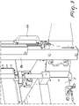
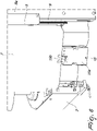
- the base frame 2 can be, optionally, stably coupled to the fixed framework of the conveyor 3 and placed on the floor by way of a pedestal 2a, as in the embodiment in Figures 7 and 8 , or it can also be detachably connected to the fixed framework of the conveyor 3 and, in such case, it can be conveniently supported by a trolley 2b for movement and conveyance, as in the embodiment in Figures 9 and 10 .
- the base frame 2 supports the labeling means 6 that make it possible to affix labels on the individual containers 4 transiting along the conveyor 3.
- the labeling means 6 can comprise a magazine 6a of labels to be applied, a device 6b for taking the labels from the magazine 6a and at least one device 6c for applying the labels to the containers 4, all of which are conventional.
- an adhesive roller 6d is provided, which is designed to apply a layer of adhesive to the labels.
- the labeling means 6 can optionally comprise a spool of backing for labels, or of film carrying printed labels, and at least one label application drum, for applying the labels obtained from such tape or film onto the containers 4, or they can be structured in any other manner that is known per se.
- the labeling assembly 1 comprises, furthermore, means for at least partially delimiting the work area of the labeling means 6, which make it possible to prevent access to such work area, in particular when the labeling means 6 are in operation.
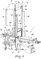
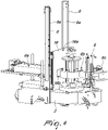
- such delimiting means comprise at least one protective body 7 which can move slideably, with respect to the base frame 2, between an active position, shown for example in Figure 1 , in which the protective body 7 delimits at least partially the work area of the labeling means 6, and at least one inactive position, which is spaced with respect to the active position, in which free access is allowed from the outside to the work area of the labeling means 6, as shown for example in Figure 2 .
- the protective body 7 is, advantageously, mounted so that it can slide along one or more guides 8 that extend substantially vertically from the base frame 2, so as to allow the protective body 7 to pass from a lowered condition with respect to the base frame 2, in which the protective body 7 is in the active position, to a raised condition with respect to the base frame 2, in which the protective body 7 is instead in the inactive position, and vice versa.
- each guide 8 is fixed to a respective post 8a that extends, substantially vertically, from the base frame 2 and is, advantageously, engaged slideably by a corresponding slider 9 which is fixed to the protective body 7, for example by way of adapted brackets 9a.
- the protective body 7 can be removably connected to the sliders 9.
- such rapid removable coupling means can, advantageously, be provided by way of a plurality of coupling bodies 22, fixed to the sliders 9 and defining respective contoured slots 23, which are engageable by corresponding connection pins 24, fixed to the protective body 7 and provided with a widened head 24a.
- the protective body 7 conveniently has at least two separate protective portions 7a and 7b, which are mutually opposite and are adapted to delimit respective mutually opposite sides of the work area of the labeling means 6.
- the protective body 7 also has an upper protection portion 7c on its upper side.
- the protective body 7 is connected to at least one counterweight 10.
- each one of the guides 8 there is a corresponding counterweight 10 connected to the protective body 7.
- each counterweight 10 is, conveniently, connected to the protective body 7 by way of a corresponding flexible elongated connecting element 11, such as for example a chain, a strap or the like, which is in engagement with a corresponding transmission pulley 12, which can rotate about its own axis with respect to the base frame 2 and is arranged substantially at an upper end of the corresponding guide 8.
- a corresponding flexible elongated connecting element 11 such as for example a chain, a strap or the like
- each counterweight 10 is accommodated in a sliding channel 13, which is defined axially inside the corresponding post 8a.
- At least one shock-absorbing device 18 can be conveniently associated with at least one of the guides 8 and act between the protective body 7 and the base frame 2, making it possible to exert a braking action on the movement of the protective body 7 between its active position and its inactive position.
- At least one handle 14 is conveniently associated with the protective body 7 and can be gripped by the operator, in order to allow him/her to conveniently perform the sliding of the protective body 7, along the guides 8, between its active position and its inactive position.
- the movement of the protective body 7 between its active position and its inactive position can be actuated by way of actuation means.
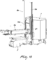
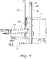
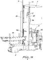
- such actuation means comprise at least one motor 20 connected functionally to a respective transmission pulley 12, as shown in Figures 17 and 18 .
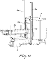
- the actuation means can comprise linear actuation means.
- such linear actuation means can be constituted by at least one fluid-operated piston 19, articulated between the base frame 2 and a corresponding slider 9.
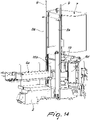
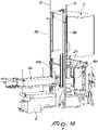
- the linear actuation means can be provided by a magnetic ring piston 21, acting between the base frame 2 and a corresponding slider 9, as illustrated in Figures 15 and 16 .
- means 15 of detection of the arrangement of the protective body 7 in the active position are further provided.
- the detection means 15 are connected to means of control of the labeling means 6 which are adapted to enable the operation of the labeling means 6, when the protective body 7 is in its active position, and to disable the operation thereof, if the protective body 7 is moved away from the active position and brought, for example, to its inactive position.
- the detection means 15 comprise a first detector element 15a, fixed to the base frame 2, and a second detector element 15b, fixed to the protective body 7 and adapted to be coupled with the first detector element 15a, when the protective body 7 is in its active position.
- the first detector element 15a conveniently has a female seat
- the second detector element 15b has a male element adapted to be removably inserted into the female seat of the first detector element 15a, when the protective body 7 is in its active position.
- control means of the labeling means 6 connected to the detection means 15 can be constituted by switching means adapted to enable/disable the electric power supply of the labeling means 6.
- switching means are in the open condition and, therefore, capable of disabling the electric power supply of the labeling means 6, when the first detector element 15a is uncoupled from the second detector element 15b and, as a consequence, when the protective body 7 is in its inactive position, while the switching means are in the closed condition, with consequent enabling of the electric power supply of the labeling means 6, when the first detector element 15a is coupled to the second detector element 15b and, therefore, the protective body 7 is in the active position.
- an additional protective body 16 supported by the base frame 2 and constituted for example by a panel 16a, conveniently provided with an opening 16b which makes it possible to connect the magazine 6a with the device 6b for taking the labels from the magazine.
- the panel 16a in order to allow access to the pickup device 6b, in the event of necessary intervention for maintenance, repair or change of format, the panel 16a can be removed individually from the base frame 2 or it can also be slideably moved with respect to the base frame 2 between a lowered condition, like that shown in Figure 4 , in which it is interposed between the magazine 6a and the pickup device 6b, and a raised condition, in which it permits easy access from outside to the area affected by the device 6b for taking the labels.
- the panel 16a can conveniently be coupled slideably to corresponding guide elements that are supported by the posts 8a.
- the additional protective body 16 can also be integrally connected to the protective body 7, so that it can be moved with the protective body 7 between the active position and the inactive position.
- the operator brings the protective body 7 to the lowered condition with respect to the base frame 2, so as to arrange it in its active position, so that it can delimit the work area of the labeling means 6.
- the detection means 15 allow the means of control of the labeling means 6 to enable the operation of the labeling means 6, so as to allow the application of the labels on the containers 4 transiting on the conveyor 3.
- the operator If it becomes necessary to intervene for maintenance, repair or change of format on the labeling means 6, the operator, with a simple operation, moves the protective body 7 to the inactive position, by making it slide along the guides 8, with the aid of the handles 14, or by activating the actuation means, so as to bring it to the raised condition with respect to the base frame 2, thus completely freeing access to the work area of the labeling means 6, without problems of hindrance by the protective body 7.
- the means of control of the labeling means 6 disable the operation of the labeling means 6, so as to prevent accidents to operators owing to elements in motion.
- the operator can return, with an equally simple operation, the protective body 7 to the lowered condition with respect to the base frame 2, by making it slide along the guides 8 or by again activating the actuation means, until it is brought back to the active position.
Landscapes
- Engineering & Computer Science (AREA)
- General Engineering & Computer Science (AREA)
- Mechanical Engineering (AREA)
- Labeling Devices (AREA)
- Transition And Organic Metals Composition Catalysts For Addition Polymerization (AREA)
- Luminescent Compositions (AREA)
- Package Frames And Binding Bands (AREA)
Description
- The present invention relates to a labeling assembly of the kind comprising the features of the preamble of
claim 1, for labeling machines. A labeling assembly in accordance with the preamble ofclaim 1 is known fromWO 2013/001551 A1 . Other labeling assemblies are known fromWO 2011/154980 A1 ,EP 2 778 082 A1EP 2 792 928 A1 - Currently, labeling machines are known for labeling containers, such as bottles, jars or the like, which have a conveyor of the containers, which is usually constituted by a carousel that can rotate about a rotation axis and is provided with supporting pans for individual containers to be labeled.
- Conventional labeling machines have, furthermore, a plurality of stations for processing the containers, which are arranged around the carousel and which comprise at least one labeling assembly for labeling the containers transiting on the carousel.
- Typically, each labeling assembly comprises a base frame, which can be coupled stably or detachably to the fixed framework of the carousel and which supports labeling means, which make it possible to affix the labels, which are taken from adapted spools or from a magazine of labels, onto containers in transit on the carousel.
- Multiple protection panels are mounted around the labeling means and make it possible to delimit the work area of the labeling means, so as to prevent accidental access thereto from outside during the operation of the machine.
- Such protection panels can be removed individually from the base frame of the labeling assembly, in order to allow operators to carry out maintenance or repair interventions or to perform changes of format on the labeling means.
- Once removed from the base frame, the panels are usually placed on the floor in proximity to the base frame, but often this is a hindrance to the convenient movements of the operators.
- Solutions are also known in which the protection panels are individually hinged to the base frame, so as to be able to pass from a closed condition, in which they delimit the space around the labeling means, to an open condition, in which they make it possible for operators to access the labeling means, and vice versa.
- In this case too, however, the protection panels can constitute an obstacle to the freedom of movement of the operators, especially in the area in which they are hinged to the base frame.
- The aim of the present invention is to provide a labeling assembly that offers an adequate protection of the work area of the labeling means, preventing access thereto during the operation of the labeling means, and which, at the same time, allows easy and convenient access to the work area of the labeling means, during maintenance or repair interventions thereon.
- Within this aim, an object of the present invention is to provide a labeling assembly that, in addition to offering the highest guarantees of reliability and safety, is also of practical use for the operators.
- Another object of the present invention is to provide a labeling assembly that is very simple in structure and which is low cost.
- This aim and these and other objects which will become better apparent hereinafter are achieved by a labeling assembly for labeling machines, according to the invention, as defined in
claim 1. - Further characteristics and advantages of the invention will become better apparent from the description of some preferred, but not exclusive, embodiments of the labeling assembly, according to the invention, which are illustrated by way of non-limiting example in the accompanying drawings wherein:
-
Figure 1 is a partial perspective view of a labeling assembly according to the invention with a protective body in an active position thereof; -
Figure 2 is a partial perspective view of the labeling assembly according to the invention with the protective body in an inactive position; -
Figure 3 is a partial perspective view of the labeling assembly according to the invention with the protective body in the inactive position and with parts removed to show the interior; -
Figure 4 shows a portion of the labeling assembly according to the invention in which a protective body has been omitted, for the sake of simplicity; -
Figure 5 is an enlarged-scale view of a detail of the labeling assembly according to the invention; -
Figure 6 is an enlarged-scale view of the detection means in the labeling assembly according to the invention; -
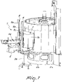
Figure 7 is a perspective view of an embodiment of the labeling assembly according to the invention, associated with a conveyor of containers and with the protective body in the active position; -
Figure 8 shows the embodiment ofFigure 7 with the protective body in the inactive position and with parts of the conveyor shown in cutaway in order to show the containers in transit thereon; -
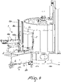
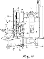
Figure 9 is a perspective view of another embodiment of the labeling assembly according to the invention, associated with a conveyor of containers and with the protective body in the active position; -
Figure 10 shows the embodiment ofFigure 9 with the protective body in the inactive position and with parts of the conveyor shown in cutaway in order to show the containers in transit thereon; -
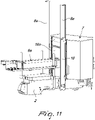
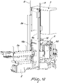
Figure 11 is a perspective view of a different embodiment of the labeling assembly according to the invention; -
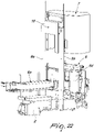
Figure 12 is a perspective view of the embodiment ofFigure 11 with the protective body in the inactive position; -
Figure 13 is a perspective view of another different embodiment of the labeling assembly according to the invention; -
Figure 14 is a perspective view of the embodiment ofFigure 13 with the protective body in the inactive position; -
Figure 15 is a perspective view of a further embodiment of the labeling assembly according to the invention; -
Figure 16 is a perspective view of the embodiment ofFigure 15 with the protective body in the inactive position; -
Figure 17 is a perspective view of a variation of embodiment of the labeling assembly according to the invention; -
Figure 18 is a perspective view of the variation of embodiment ofFigure 17 with the protective body in the inactive position; -
Figure 19 is a perspective view of another embodiment of the labeling assembly according to the invention, in which the protective body is shown in the inactive position and separated from sliders; -
Figure 20 shows a detail of the embodiment ofFigure 19 showing the rapid removable coupling means; -
Figure 21 is a perspective view of a different embodiment of the labeling assembly according to the invention; -
Figure 22 is a perspective view of the embodiment ofFigure 21 with the protective body in the inactive position. - With reference to the figures, a labeling assembly for labeling machines, generally designated with the
reference numeral 1, comprises abase frame 2 which is adapted to be associated with aconveyor 3 ofcontainers 4 to be labeled, which is constituted, for example, by arotating carousel 5. - The
base frame 2 can be, optionally, stably coupled to the fixed framework of theconveyor 3 and placed on the floor by way of apedestal 2a, as in the embodiment inFigures 7 and8 , or it can also be detachably connected to the fixed framework of theconveyor 3 and, in such case, it can be conveniently supported by atrolley 2b for movement and conveyance, as in the embodiment inFigures 9 and10 . - In particular, the
base frame 2 supports the labeling means 6 that make it possible to affix labels on theindividual containers 4 transiting along theconveyor 3. - For example, as in the embodiments shown, the labeling means 6 can comprise a
magazine 6a of labels to be applied, adevice 6b for taking the labels from themagazine 6a and at least onedevice 6c for applying the labels to thecontainers 4, all of which are conventional. Conveniently, between thepickup device 6b and theapplication device 6c anadhesive roller 6d is provided, which is designed to apply a layer of adhesive to the labels. - Alternatively, according to other possible embodiments, not shown, the labeling means 6 can optionally comprise a spool of backing for labels, or of film carrying printed labels, and at least one label application drum, for applying the labels obtained from such tape or film onto the
containers 4, or they can be structured in any other manner that is known per se. - The
labeling assembly 1 comprises, furthermore, means for at least partially delimiting the work area of the labeling means 6, which make it possible to prevent access to such work area, in particular when the labeling means 6 are in operation. - According to the invention, such delimiting means comprise at least one
protective body 7 which can move slideably, with respect to thebase frame 2, between an active position, shown for example inFigure 1 , in which theprotective body 7 delimits at least partially the work area of the labeling means 6, and at least one inactive position, which is spaced with respect to the active position, in which free access is allowed from the outside to the work area of the labeling means 6, as shown for example inFigure 2 . - In more detail, the
protective body 7 is, advantageously, mounted so that it can slide along one ormore guides 8 that extend substantially vertically from thebase frame 2, so as to allow theprotective body 7 to pass from a lowered condition with respect to thebase frame 2, in which theprotective body 7 is in the active position, to a raised condition with respect to thebase frame 2, in which theprotective body 7 is instead in the inactive position, and vice versa. - Conveniently, each
guide 8 is fixed to arespective post 8a that extends, substantially vertically, from thebase frame 2 and is, advantageously, engaged slideably by acorresponding slider 9 which is fixed to theprotective body 7, for example by way of adaptedbrackets 9a. - Optionally, the
protective body 7 can be removably connected to thesliders 9. - In particular, as shown in
Figures 19 and20 , there can be, for example, rapid removable coupling means between theprotective body 7 and thesliders 9. - As shown, in particular, in
Figure 20 , such rapid removable coupling means can, advantageously, be provided by way of a plurality ofcoupling bodies 22, fixed to thesliders 9 and defining respective contouredslots 23, which are engageable bycorresponding connection pins 24, fixed to theprotective body 7 and provided with a widenedhead 24a. - As illustrated, the
protective body 7 conveniently has at least two separateprotective portions - In this manner, moving the
protective body 7 from the active position to the inactive position makes it possible to free access to the work area of the labeling means 6 on both its opposite sides. - Preferably, the
protective body 7 also has anupper protection portion 7c on its upper side. - Advantageously, in order to facilitate its movement by the operators along the
guides 8 between the active position and the inactive position, theprotective body 7 is connected to at least onecounterweight 10. - Preferably, for each one of the
guides 8, there is acorresponding counterweight 10 connected to theprotective body 7. - As shown in
Figure 3 , eachcounterweight 10 is, conveniently, connected to theprotective body 7 by way of a corresponding flexible elongated connectingelement 11, such as for example a chain, a strap or the like, which is in engagement with acorresponding transmission pulley 12, which can rotate about its own axis with respect to thebase frame 2 and is arranged substantially at an upper end of thecorresponding guide 8. - Advantageously, again as shown in
Figure 3 , eachcounterweight 10 is accommodated in asliding channel 13, which is defined axially inside thecorresponding post 8a. - Optionally, as shown for example in
Figures 11 and12 , at least one shock-absorbingdevice 18 can be conveniently associated with at least one of theguides 8 and act between theprotective body 7 and thebase frame 2, making it possible to exert a braking action on the movement of theprotective body 7 between its active position and its inactive position. - As shown in particular in
Figure 5 , at least onehandle 14 is conveniently associated with theprotective body 7 and can be gripped by the operator, in order to allow him/her to conveniently perform the sliding of theprotective body 7, along theguides 8, between its active position and its inactive position. - Optionally, the movement of the
protective body 7 between its active position and its inactive position can be actuated by way of actuation means. - For example, such actuation means comprise at least one
motor 20 connected functionally to arespective transmission pulley 12, as shown inFigures 17 and18 . - According to a possible variation, the actuation means can comprise linear actuation means.
- In particular, as shown in
Figures 13 and14 , such linear actuation means can be constituted by at least one fluid-operatedpiston 19, articulated between thebase frame 2 and acorresponding slider 9. Alternatively, the linear actuation means can be provided by amagnetic ring piston 21, acting between thebase frame 2 and acorresponding slider 9, as illustrated inFigures 15 and16 . - Advantageously, means 15 of detection of the arrangement of the
protective body 7 in the active position are further provided. - Conveniently, the detection means 15 are connected to means of control of the labeling means 6 which are adapted to enable the operation of the labeling means 6, when the
protective body 7 is in its active position, and to disable the operation thereof, if theprotective body 7 is moved away from the active position and brought, for example, to its inactive position. - In more detail, the detection means 15 comprise a
first detector element 15a, fixed to thebase frame 2, and asecond detector element 15b, fixed to theprotective body 7 and adapted to be coupled with thefirst detector element 15a, when theprotective body 7 is in its active position. - In particular, the
first detector element 15a conveniently has a female seat, while thesecond detector element 15b has a male element adapted to be removably inserted into the female seat of thefirst detector element 15a, when theprotective body 7 is in its active position. - Advantageously, the control means of the labeling means 6 connected to the detection means 15 can be constituted by switching means adapted to enable/disable the electric power supply of the labeling means 6.
- More specifically, such switching means are in the open condition and, therefore, capable of disabling the electric power supply of the labeling means 6, when the
first detector element 15a is uncoupled from thesecond detector element 15b and, as a consequence, when theprotective body 7 is in its inactive position, while the switching means are in the closed condition, with consequent enabling of the electric power supply of the labeling means 6, when thefirst detector element 15a is coupled to thesecond detector element 15b and, therefore, theprotective body 7 is in the active position. - As shown in particular in
Figure 4 , on the side of theprotective body 7 directed toward themagazine 6a there can be an additionalprotective body 16 supported by thebase frame 2 and constituted for example by apanel 16a, conveniently provided with anopening 16b which makes it possible to connect themagazine 6a with thedevice 6b for taking the labels from the magazine. - Conveniently, in order to allow access to the
pickup device 6b, in the event of necessary intervention for maintenance, repair or change of format, thepanel 16a can be removed individually from thebase frame 2 or it can also be slideably moved with respect to thebase frame 2 between a lowered condition, like that shown inFigure 4 , in which it is interposed between themagazine 6a and thepickup device 6b, and a raised condition, in which it permits easy access from outside to the area affected by thedevice 6b for taking the labels. In this latter case, thepanel 16a can conveniently be coupled slideably to corresponding guide elements that are supported by theposts 8a. - Alternatively, as shown in
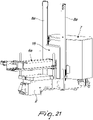
Figures 21 and22 , the additionalprotective body 16 can also be integrally connected to theprotective body 7, so that it can be moved with theprotective body 7 between the active position and the inactive position. - Operation of the labeling assembly according to the invention is the following.
- With the labeling assembly associated with the
conveyor 3 of thecontainers 4, the operator brings theprotective body 7 to the lowered condition with respect to thebase frame 2, so as to arrange it in its active position, so that it can delimit the work area of the labeling means 6. - In such condition, the detection means 15 allow the means of control of the labeling means 6 to enable the operation of the labeling means 6, so as to allow the application of the labels on the
containers 4 transiting on theconveyor 3. - If it becomes necessary to intervene for maintenance, repair or change of format on the labeling means 6, the operator, with a simple operation, moves the
protective body 7 to the inactive position, by making it slide along theguides 8, with the aid of thehandles 14, or by activating the actuation means, so as to bring it to the raised condition with respect to thebase frame 2, thus completely freeing access to the work area of the labeling means 6, without problems of hindrance by theprotective body 7. - In such situation, the means of control of the labeling means 6 disable the operation of the labeling means 6, so as to prevent accidents to operators owing to elements in motion.
- Once the necessary interventions on the labeling means 6 are finished, the operator can return, with an equally simple operation, the
protective body 7 to the lowered condition with respect to thebase frame 2, by making it slide along theguides 8 or by again activating the actuation means, until it is brought back to the active position. - In practice it has been found that the invention is capable of fully achieving the set aim and objects.
- All the characteristics of the invention, indicated above as advantageous, convenient or similar, may also be missing or be substituted by equivalent characteristics.
- The individual characteristics set out in reference to general teachings or to specific embodiments may all be present in other embodiments or may substitute characteristics in such embodiments.
- The invention, thus conceived, is susceptible of numerous modifications and variations, as long as they are within the scope of the appended claims.
- In practice the materials employed, provided they are compatible with the specific use, and the dimensions and shapes, may be any according to requirements.
- Where technical features mentioned in any claim are followed by reference signs, those reference signs have been included for the sole purpose of increasing the intelligibility of the claims and accordingly, such reference signs do not have any limiting effect on the interpretation of each element identified by way of example by such reference signs.
Claims (11)
- A labeling assembly for labeling machines, which comprises a base frame (2) which is adapted to be associated with a conveyor (3) of containers (4) to be labeled, wherein the base frame (2) supports labeling means (6) for labeling said containers (4), the labeling assembly comprising delimiting means for at least partially delimiting the work area of said labeling means (6), said delimiting means comprising at least one protective body (70), characterized in that said protective body (7) can move slideably, with respect to said base frame (2), between an active position, in which said protective body (7) is adapted to delimit at least partially the work area of said labeling means (6), and at least one inactive position, which is spaced with respect to said active position, in which said protective body (7) allows access from the outside to the work area of said labeling means (6).
- The labeling assembly according to claim 1, characterized in that said at least one protective body (7) is mounted so that it can slide along at least one guide (8) which extends substantially vertically from said base frame (2), in order to pass from a lowered condition with respect to said base frame (2), in which said at least one protective body (7) is in said active position, to a raised condition with respect to said base frame (2), in which said at least one protective body (7) is in said inactive position, and vice versa.
- The labeling assembly according to one or more of the preceding claims, characterized in that said at least one protective body (7) forms at least two protective portions (7a, 7b) which are mutually opposite and are adapted to delimit respective mutually opposite sides of the work area of said labeling means (6).
- The labeling assembly according to one or more of the preceding claims, characterized in that said at least one protective body (7) is connected to at least one counterweight (10).
- The labeling assembly according to one or more of the preceding claims, characterized in that said at least one protective body (7) is connected to said at least one counterweight by way of a flexible elongated connecting element (11) that engages a transmission pulley (12), which can rotate about its own axis with respect to said base frame (2) and is arranged substantially at an upper end of said at least one guide (8).
- The labeling assembly according to one or more of the preceding claims, characterized in that it comprises at least one shock-absorbing device (18), which acts between said protective body (7) and said base frame (2).
- The labeling assembly according to one or more of the preceding claims, characterized in that it comprises actuation means adapted to move said protective body (7) between said active position and said inactive position.
- The labeling assembly according to one or more of the preceding claims, characterized in that the labelling means comprise a magazine (6a) of labels to be applied, a device (6b) for taking the labels from the magazine (6a), and at least one device (6c) for applying the labels to the containers (4), wherein the labelling assembly comprises, on the side of said protective body (7) that is directed toward a label magazine (6a), an additional protective body (16).
- The labeling assembly according to claim 8, characterized in that said additional protective body (16) is integral with said protective body (7).
- The labeling assembly according to one or more of the preceding claims, characterized in that it comprises detection means (15) for detecting the arrangement of said at least one protective body (7) in said active position.
- The labeling assembly according to claim 10, characterized in that said detection means (15) are connected to means of control of said labeling means (6) which are adapted to enable the operation of said labeling means (6) with said at least one protective body (7) in said active position.
Applications Claiming Priority (2)
| Application Number | Priority Date | Filing Date | Title |
|---|---|---|---|
| ITUB2015A006259A ITUB20156259A1 (en) | 2015-12-04 | 2015-12-04 | LABELING GROUP FOR LABELING MACHINES. |
| PCT/EP2016/079416 WO2017093392A1 (en) | 2015-12-04 | 2016-12-01 | Labeling assembly for labeling machines |
Publications (2)
| Publication Number | Publication Date |
|---|---|
| EP3383750A1 EP3383750A1 (en) | 2018-10-10 |
| EP3383750B1 true EP3383750B1 (en) | 2022-06-29 |
Family
ID=55538472
Family Applications (1)
| Application Number | Title | Priority Date | Filing Date |
|---|---|---|---|
| EP16815561.2A Active EP3383750B1 (en) | 2015-12-04 | 2016-12-01 | Labeling assembly for labeling machines |
Country Status (9)
| Country | Link |
|---|---|
| US (1) | US10800568B2 (en) |
| EP (1) | EP3383750B1 (en) |
| BR (1) | BR112018010376B1 (en) |
| CA (1) | CA3006327C (en) |
| ES (1) | ES2924485T3 (en) |
| IT (1) | ITUB20156259A1 (en) |
| MX (1) | MX2018006730A (en) |
| PL (1) | PL3383750T3 (en) |
| WO (1) | WO2017093392A1 (en) |
Families Citing this family (6)
| Publication number | Priority date | Publication date | Assignee | Title |
|---|---|---|---|---|
| IT201800005843A1 (en) * | 2018-05-30 | 2019-11-30 | LABELING MACHINE. | |
| IT202100013058A1 (en) * | 2021-05-20 | 2022-11-20 | Pe Labellers Spa | CONTAINER TREATMENT MACHINE. |
| IT202100023630A1 (en) * | 2021-09-14 | 2023-03-14 | Pe Labellers Spa | LABEL MACHINE. |
| US12415643B2 (en) | 2021-09-14 | 2025-09-16 | P.E. Labellers S.P.A. | Labeling assembly for labeling machines |
| DE102022122085A1 (en) | 2022-08-31 | 2024-02-29 | Krones Aktiengesellschaft | Device and method for forming plastic preforms into plastic containers with a clean room with a removable lid device |
| DE102023114693A1 (en) * | 2023-06-05 | 2024-12-05 | Krones Aktiengesellschaft | Device for marking containers and associated operating procedure |
Citations (15)
| Publication number | Priority date | Publication date | Assignee | Title |
|---|---|---|---|---|
| DE2150310A1 (en) | 1971-10-08 | 1973-04-12 | Tom T Mikulin | SAFETY DEVICE |
| GB1344639A (en) | 1971-09-28 | 1974-01-23 | Mikulin T T | |
| EP1607335A1 (en) | 2004-06-19 | 2005-12-21 | KHS Maschinen- und Anlagenbau Aktiengesellschaft | Apparatus for labelling containers |
| EP1627816A1 (en) | 2004-08-21 | 2006-02-22 | KHS Maschinen- und Anlagenbau Aktiengesellschaft | Method for labelling containers and labelling machine for carrying out the method |
| WO2012019824A1 (en) | 2010-08-13 | 2012-02-16 | P.E. Labellers S.P.A. | Labeling machine, particularly for labeling containers |
| US20120039692A1 (en) | 2009-03-04 | 2012-02-16 | Mattia Giuliani | Protection system for container treatment machines |
| WO2012146501A1 (en) | 2011-04-28 | 2012-11-01 | P.E. Labellers S.P.A. | Carousel labeling machine for pre-glued labels on a ribbon |
| DE102013100927A1 (en) | 2012-02-02 | 2013-08-08 | Fanuc Corporation | Covering device for a machine tool |
| DE102012003354A1 (en) | 2012-02-21 | 2013-08-22 | Khs Gmbh | Method for labeling containers and labeling machine |
| US20140306393A1 (en) | 2013-04-15 | 2014-10-16 | Krones Ag | Container treatment machine |
| US20140306391A1 (en) | 2013-04-15 | 2014-10-16 | Krones Ag | Container treatment machine |
| DE102013206671A1 (en) | 2013-04-15 | 2014-10-16 | Krones Ag | Equipment machine for containers |
| DE102013109691A1 (en) | 2013-06-27 | 2014-12-31 | Khs Gmbh | Method and labeling machine for labeling containers |
| DE102013114614A1 (en) | 2013-12-20 | 2015-06-25 | Khs Gmbh | Protective cover for a container treatment machine as well as container treatment machine |
| DE202015105183U1 (en) | 2015-10-01 | 2015-10-13 | Krones Ag | Treatment machine for containers |
Family Cites Families (5)
| Publication number | Priority date | Publication date | Assignee | Title |
|---|---|---|---|---|
| US7185689B2 (en) * | 2000-10-17 | 2007-03-06 | Kolinahr Systems, Inc. | Pallet labeler system |
| CN103003160B (en) | 2010-06-11 | 2014-07-09 | 西得乐独资股份公司 | Labelling machine |
| WO2013001551A1 (en) * | 2011-06-28 | 2013-01-03 | Kosme S.R.L. Unipersonale | Labelling machine with carrousel |
| DE102013204123A1 (en) * | 2013-03-11 | 2014-09-11 | Krones Ag | Labeling machine for vessels |
| EP2927139B1 (en) * | 2014-03-31 | 2017-10-11 | Sidel S.p.a. Con Socio Unico | Machine and method for labelling articles |
-
2015
- 2015-12-04 IT ITUB2015A006259A patent/ITUB20156259A1/en unknown
-
2016
- 2016-12-01 WO PCT/EP2016/079416 patent/WO2017093392A1/en not_active Ceased
- 2016-12-01 EP EP16815561.2A patent/EP3383750B1/en active Active
- 2016-12-01 CA CA3006327A patent/CA3006327C/en active Active
- 2016-12-01 ES ES16815561T patent/ES2924485T3/en active Active
- 2016-12-01 MX MX2018006730A patent/MX2018006730A/en unknown
- 2016-12-01 PL PL16815561.2T patent/PL3383750T3/en unknown
- 2016-12-01 US US15/780,703 patent/US10800568B2/en active Active
- 2016-12-01 BR BR112018010376-4A patent/BR112018010376B1/en active IP Right Grant
Patent Citations (15)
| Publication number | Priority date | Publication date | Assignee | Title |
|---|---|---|---|---|
| GB1344639A (en) | 1971-09-28 | 1974-01-23 | Mikulin T T | |
| DE2150310A1 (en) | 1971-10-08 | 1973-04-12 | Tom T Mikulin | SAFETY DEVICE |
| EP1607335A1 (en) | 2004-06-19 | 2005-12-21 | KHS Maschinen- und Anlagenbau Aktiengesellschaft | Apparatus for labelling containers |
| EP1627816A1 (en) | 2004-08-21 | 2006-02-22 | KHS Maschinen- und Anlagenbau Aktiengesellschaft | Method for labelling containers and labelling machine for carrying out the method |
| US20120039692A1 (en) | 2009-03-04 | 2012-02-16 | Mattia Giuliani | Protection system for container treatment machines |
| WO2012019824A1 (en) | 2010-08-13 | 2012-02-16 | P.E. Labellers S.P.A. | Labeling machine, particularly for labeling containers |
| WO2012146501A1 (en) | 2011-04-28 | 2012-11-01 | P.E. Labellers S.P.A. | Carousel labeling machine for pre-glued labels on a ribbon |
| DE102013100927A1 (en) | 2012-02-02 | 2013-08-08 | Fanuc Corporation | Covering device for a machine tool |
| DE102012003354A1 (en) | 2012-02-21 | 2013-08-22 | Khs Gmbh | Method for labeling containers and labeling machine |
| US20140306393A1 (en) | 2013-04-15 | 2014-10-16 | Krones Ag | Container treatment machine |
| US20140306391A1 (en) | 2013-04-15 | 2014-10-16 | Krones Ag | Container treatment machine |
| DE102013206671A1 (en) | 2013-04-15 | 2014-10-16 | Krones Ag | Equipment machine for containers |
| DE102013109691A1 (en) | 2013-06-27 | 2014-12-31 | Khs Gmbh | Method and labeling machine for labeling containers |
| DE102013114614A1 (en) | 2013-12-20 | 2015-06-25 | Khs Gmbh | Protective cover for a container treatment machine as well as container treatment machine |
| DE202015105183U1 (en) | 2015-10-01 | 2015-10-13 | Krones Ag | Treatment machine for containers |
Also Published As
| Publication number | Publication date |
|---|---|
| BR112018010376A2 (en) | 2018-12-04 |
| ES2924485T3 (en) | 2022-10-07 |
| ITUB20156259A1 (en) | 2017-06-04 |
| CA3006327A1 (en) | 2017-06-08 |
| MX2018006730A (en) | 2018-08-01 |
| PL3383750T3 (en) | 2022-11-14 |
| US10800568B2 (en) | 2020-10-13 |
| WO2017093392A1 (en) | 2017-06-08 |
| CA3006327C (en) | 2024-03-12 |
| EP3383750A1 (en) | 2018-10-10 |
| BR112018010376B1 (en) | 2022-11-22 |
| US20180354670A1 (en) | 2018-12-13 |
Similar Documents
| Publication | Publication Date | Title |
|---|---|---|
| EP3383750B1 (en) | Labeling assembly for labeling machines | |
| CN108473222B (en) | Conveyor for containers | |
| US6553746B1 (en) | Device for automatically changing reels of film | |
| CA3093344C (en) | Apparatuses for wrapping a load and supplying film for wrapping a load and associated methods | |
| EP2778082B1 (en) | Labelling machine for vessels | |
| CA2805863C (en) | Apparatus and method for applying a label to a non-ruled surface | |
| MX2012014073A (en) | Labelling machine. | |
| CA2930075C (en) | Adhesive applicator | |
| KR20180056640A (en) | The elevator carriage operating device and the elevator carriage | |
| KR101205709B1 (en) | A detach and attach apparayus of bar code label sticker | |
| ITVR20110146A1 (en) | LABEL STATION SUPPORT TROLLEY IN THE MACHINE LABELING MACHINE | |
| JP5194277B2 (en) | Apparatus and method for applying labels | |
| ES2550369B1 (en) | Automatic format change device for automatic horizontal machine forming and filling flexible packaging | |
| RU2016112606A (en) | MARKING MACHINE | |
| US12415643B2 (en) | Labeling assembly for labeling machines | |
| EP2951018B1 (en) | Machine and method for marking articles | |
| JP7032844B2 (en) | Label affixing device and label affixing machine equipped with it | |
| US9199501B2 (en) | Feed module for supplying stamping foil | |
| GB1593738A (en) | Conveyor system for use in assembling and/or machining workpieces | |
| US11535413B2 (en) | Vacuum drum for a labeling unit, and labeling unit having a vacuum drum of this type | |
| CN209536395U (en) | A kind of automation top cover working position apparatus | |
| CN113911493B (en) | Air bag cover plate labeling device | |
| CN102774708B (en) | Weaving preprocessor changes canister and the method for changing tank | |
| EP4472896B1 (en) | Labelling machine with a footboard | |
| CN208360609U (en) | A kind of type box opening mechanism and its automatic box packing machine |
Legal Events
| Date | Code | Title | Description |
|---|---|---|---|
| STAA | Information on the status of an ep patent application or granted ep patent |
Free format text: STATUS: UNKNOWN |
|
| STAA | Information on the status of an ep patent application or granted ep patent |
Free format text: STATUS: THE INTERNATIONAL PUBLICATION HAS BEEN MADE |
|
| PUAI | Public reference made under article 153(3) epc to a published international application that has entered the european phase |
Free format text: ORIGINAL CODE: 0009012 |
|
| STAA | Information on the status of an ep patent application or granted ep patent |
Free format text: STATUS: REQUEST FOR EXAMINATION WAS MADE |
|
| 17P | Request for examination filed |
Effective date: 20180621 |
|
| AK | Designated contracting states |
Kind code of ref document: A1 Designated state(s): AL AT BE BG CH CY CZ DE DK EE ES FI FR GB GR HR HU IE IS IT LI LT LU LV MC MK MT NL NO PL PT RO RS SE SI SK SM TR |
|
| AX | Request for extension of the european patent |
Extension state: BA ME |
|
| DAV | Request for validation of the european patent (deleted) | ||
| DAX | Request for extension of the european patent (deleted) | ||
| RAP1 | Party data changed (applicant data changed or rights of an application transferred) |
Owner name: P.E. LABELLERS S.P.A. |
|
| RIC1 | Information provided on ipc code assigned before grant |
Ipc: F16P 3/08 20060101ALI20211214BHEP Ipc: F16M 1/02 20060101ALI20211214BHEP Ipc: B65C 9/40 20060101ALI20211214BHEP Ipc: B65C 9/00 20060101AFI20211214BHEP |
|
| GRAP | Despatch of communication of intention to grant a patent |
Free format text: ORIGINAL CODE: EPIDOSNIGR1 |
|
| STAA | Information on the status of an ep patent application or granted ep patent |
Free format text: STATUS: GRANT OF PATENT IS INTENDED |
|
| INTG | Intention to grant announced |
Effective date: 20220121 |
|
| GRAS | Grant fee paid |
Free format text: ORIGINAL CODE: EPIDOSNIGR3 |
|
| GRAA | (expected) grant |
Free format text: ORIGINAL CODE: 0009210 |
|
| STAA | Information on the status of an ep patent application or granted ep patent |
Free format text: STATUS: THE PATENT HAS BEEN GRANTED |
|
| AK | Designated contracting states |
Kind code of ref document: B1 Designated state(s): AL AT BE BG CH CY CZ DE DK EE ES FI FR GB GR HR HU IE IS IT LI LT LU LV MC MK MT NL NO PL PT RO RS SE SI SK SM TR |
|
| REG | Reference to a national code |
Ref country code: CH Ref legal event code: EP |
|
| REG | Reference to a national code |
Ref country code: AT Ref legal event code: REF Ref document number: 1501211 Country of ref document: AT Kind code of ref document: T Effective date: 20220715 |
|
| REG | Reference to a national code |
Ref country code: IE Ref legal event code: FG4D |
|
| REG | Reference to a national code |
Ref country code: DE Ref legal event code: R096 Ref document number: 602016073200 Country of ref document: DE |
|
| REG | Reference to a national code |
Ref country code: SE Ref legal event code: TRGR |
|
| REG | Reference to a national code |
Ref country code: NL Ref legal event code: FP |
|
| REG | Reference to a national code |
Ref country code: ES Ref legal event code: FG2A Ref document number: 2924485 Country of ref document: ES Kind code of ref document: T3 Effective date: 20221007 |
|
| REG | Reference to a national code |
Ref country code: LT Ref legal event code: MG9D |
|
| PG25 | Lapsed in a contracting state [announced via postgrant information from national office to epo] |
Ref country code: NO Free format text: LAPSE BECAUSE OF FAILURE TO SUBMIT A TRANSLATION OF THE DESCRIPTION OR TO PAY THE FEE WITHIN THE PRESCRIBED TIME-LIMIT Effective date: 20220929 Ref country code: LT Free format text: LAPSE BECAUSE OF FAILURE TO SUBMIT A TRANSLATION OF THE DESCRIPTION OR TO PAY THE FEE WITHIN THE PRESCRIBED TIME-LIMIT Effective date: 20220629 Ref country code: HR Free format text: LAPSE BECAUSE OF FAILURE TO SUBMIT A TRANSLATION OF THE DESCRIPTION OR TO PAY THE FEE WITHIN THE PRESCRIBED TIME-LIMIT Effective date: 20220629 Ref country code: GR Free format text: LAPSE BECAUSE OF FAILURE TO SUBMIT A TRANSLATION OF THE DESCRIPTION OR TO PAY THE FEE WITHIN THE PRESCRIBED TIME-LIMIT Effective date: 20220930 Ref country code: FI Free format text: LAPSE BECAUSE OF FAILURE TO SUBMIT A TRANSLATION OF THE DESCRIPTION OR TO PAY THE FEE WITHIN THE PRESCRIBED TIME-LIMIT Effective date: 20220629 Ref country code: BG Free format text: LAPSE BECAUSE OF FAILURE TO SUBMIT A TRANSLATION OF THE DESCRIPTION OR TO PAY THE FEE WITHIN THE PRESCRIBED TIME-LIMIT Effective date: 20220929 |
|
| PG25 | Lapsed in a contracting state [announced via postgrant information from national office to epo] |
Ref country code: RS Free format text: LAPSE BECAUSE OF FAILURE TO SUBMIT A TRANSLATION OF THE DESCRIPTION OR TO PAY THE FEE WITHIN THE PRESCRIBED TIME-LIMIT Effective date: 20220629 Ref country code: LV Free format text: LAPSE BECAUSE OF FAILURE TO SUBMIT A TRANSLATION OF THE DESCRIPTION OR TO PAY THE FEE WITHIN THE PRESCRIBED TIME-LIMIT Effective date: 20220629 |
|
| PG25 | Lapsed in a contracting state [announced via postgrant information from national office to epo] |
Ref country code: SM Free format text: LAPSE BECAUSE OF FAILURE TO SUBMIT A TRANSLATION OF THE DESCRIPTION OR TO PAY THE FEE WITHIN THE PRESCRIBED TIME-LIMIT Effective date: 20220629 Ref country code: SK Free format text: LAPSE BECAUSE OF FAILURE TO SUBMIT A TRANSLATION OF THE DESCRIPTION OR TO PAY THE FEE WITHIN THE PRESCRIBED TIME-LIMIT Effective date: 20220629 Ref country code: RO Free format text: LAPSE BECAUSE OF FAILURE TO SUBMIT A TRANSLATION OF THE DESCRIPTION OR TO PAY THE FEE WITHIN THE PRESCRIBED TIME-LIMIT Effective date: 20220629 Ref country code: PT Free format text: LAPSE BECAUSE OF FAILURE TO SUBMIT A TRANSLATION OF THE DESCRIPTION OR TO PAY THE FEE WITHIN THE PRESCRIBED TIME-LIMIT Effective date: 20221031 Ref country code: EE Free format text: LAPSE BECAUSE OF FAILURE TO SUBMIT A TRANSLATION OF THE DESCRIPTION OR TO PAY THE FEE WITHIN THE PRESCRIBED TIME-LIMIT Effective date: 20220629 |
|
| PG25 | Lapsed in a contracting state [announced via postgrant information from national office to epo] |
Ref country code: IS Free format text: LAPSE BECAUSE OF FAILURE TO SUBMIT A TRANSLATION OF THE DESCRIPTION OR TO PAY THE FEE WITHIN THE PRESCRIBED TIME-LIMIT Effective date: 20221029 |
|
| REG | Reference to a national code |
Ref country code: DE Ref legal event code: R026 Ref document number: 602016073200 Country of ref document: DE |
|
| PG25 | Lapsed in a contracting state [announced via postgrant information from national office to epo] |
Ref country code: AL Free format text: LAPSE BECAUSE OF FAILURE TO SUBMIT A TRANSLATION OF THE DESCRIPTION OR TO PAY THE FEE WITHIN THE PRESCRIBED TIME-LIMIT Effective date: 20220629 |
|
| PLBI | Opposition filed |
Free format text: ORIGINAL CODE: 0009260 |
|
| PLAX | Notice of opposition and request to file observation + time limit sent |
Free format text: ORIGINAL CODE: EPIDOSNOBS2 |
|
| PG25 | Lapsed in a contracting state [announced via postgrant information from national office to epo] |
Ref country code: DK Free format text: LAPSE BECAUSE OF FAILURE TO SUBMIT A TRANSLATION OF THE DESCRIPTION OR TO PAY THE FEE WITHIN THE PRESCRIBED TIME-LIMIT Effective date: 20220629 Ref country code: CZ Free format text: LAPSE BECAUSE OF FAILURE TO SUBMIT A TRANSLATION OF THE DESCRIPTION OR TO PAY THE FEE WITHIN THE PRESCRIBED TIME-LIMIT Effective date: 20220629 |
|
| 26 | Opposition filed |
Opponent name: KHS GMBH Effective date: 20230328 |
|
| P01 | Opt-out of the competence of the unified patent court (upc) registered |
Effective date: 20230530 |
|
| PLBB | Reply of patent proprietor to notice(s) of opposition received |
Free format text: ORIGINAL CODE: EPIDOSNOBS3 |
|
| PG25 | Lapsed in a contracting state [announced via postgrant information from national office to epo] |
Ref country code: SI Free format text: LAPSE BECAUSE OF FAILURE TO SUBMIT A TRANSLATION OF THE DESCRIPTION OR TO PAY THE FEE WITHIN THE PRESCRIBED TIME-LIMIT Effective date: 20220629 Ref country code: LU Free format text: LAPSE BECAUSE OF NON-PAYMENT OF DUE FEES Effective date: 20221201 |
|
| PG25 | Lapsed in a contracting state [announced via postgrant information from national office to epo] |
Ref country code: IE Free format text: LAPSE BECAUSE OF NON-PAYMENT OF DUE FEES Effective date: 20221201 |
|
| REG | Reference to a national code |
Ref country code: AT Ref legal event code: MM01 Ref document number: 1501211 Country of ref document: AT Kind code of ref document: T Effective date: 20221201 |
|
| PG25 | Lapsed in a contracting state [announced via postgrant information from national office to epo] |
Ref country code: HU Free format text: LAPSE BECAUSE OF FAILURE TO SUBMIT A TRANSLATION OF THE DESCRIPTION OR TO PAY THE FEE WITHIN THE PRESCRIBED TIME-LIMIT; INVALID AB INITIO Effective date: 20161201 |
|
| PG25 | Lapsed in a contracting state [announced via postgrant information from national office to epo] |
Ref country code: AT Free format text: LAPSE BECAUSE OF NON-PAYMENT OF DUE FEES Effective date: 20221201 |
|
| PG25 | Lapsed in a contracting state [announced via postgrant information from national office to epo] |
Ref country code: CY Free format text: LAPSE BECAUSE OF FAILURE TO SUBMIT A TRANSLATION OF THE DESCRIPTION OR TO PAY THE FEE WITHIN THE PRESCRIBED TIME-LIMIT Effective date: 20220629 Ref country code: AT Free format text: LAPSE BECAUSE OF NON-PAYMENT OF DUE FEES Effective date: 20221201 |
|
| PG25 | Lapsed in a contracting state [announced via postgrant information from national office to epo] |
Ref country code: MK Free format text: LAPSE BECAUSE OF FAILURE TO SUBMIT A TRANSLATION OF THE DESCRIPTION OR TO PAY THE FEE WITHIN THE PRESCRIBED TIME-LIMIT Effective date: 20220629 |
|
| PG25 | Lapsed in a contracting state [announced via postgrant information from national office to epo] |
Ref country code: MC Free format text: LAPSE BECAUSE OF FAILURE TO SUBMIT A TRANSLATION OF THE DESCRIPTION OR TO PAY THE FEE WITHIN THE PRESCRIBED TIME-LIMIT Effective date: 20220629 |
|
| PG25 | Lapsed in a contracting state [announced via postgrant information from national office to epo] |
Ref country code: MC Free format text: LAPSE BECAUSE OF FAILURE TO SUBMIT A TRANSLATION OF THE DESCRIPTION OR TO PAY THE FEE WITHIN THE PRESCRIBED TIME-LIMIT Effective date: 20220629 |
|
| REG | Reference to a national code |
Ref country code: DE Ref legal event code: R100 Ref document number: 602016073200 Country of ref document: DE |
|
| PG25 | Lapsed in a contracting state [announced via postgrant information from national office to epo] |
Ref country code: MT Free format text: LAPSE BECAUSE OF FAILURE TO SUBMIT A TRANSLATION OF THE DESCRIPTION OR TO PAY THE FEE WITHIN THE PRESCRIBED TIME-LIMIT Effective date: 20220629 |
|
| PLCK | Communication despatched that opposition was rejected |
Free format text: ORIGINAL CODE: EPIDOSNREJ1 |
|
| PG25 | Lapsed in a contracting state [announced via postgrant information from national office to epo] |
Ref country code: BG Free format text: LAPSE BECAUSE OF FAILURE TO SUBMIT A TRANSLATION OF THE DESCRIPTION OR TO PAY THE FEE WITHIN THE PRESCRIBED TIME-LIMIT Effective date: 20220629 |
|
| REG | Reference to a national code |
Ref country code: AT Ref legal event code: UEP Ref document number: 1501211 Country of ref document: AT Kind code of ref document: T Effective date: 20220629 |
|
| PG25 | Lapsed in a contracting state [announced via postgrant information from national office to epo] |
Ref country code: BG Free format text: LAPSE BECAUSE OF FAILURE TO SUBMIT A TRANSLATION OF THE DESCRIPTION OR TO PAY THE FEE WITHIN THE PRESCRIBED TIME-LIMIT Effective date: 20220629 |
|
| PLBN | Opposition rejected |
Free format text: ORIGINAL CODE: 0009273 |
|
| STAA | Information on the status of an ep patent application or granted ep patent |
Free format text: STATUS: OPPOSITION REJECTED |
|
| 27O | Opposition rejected |
Effective date: 20240926 |
|
| PGFP | Annual fee paid to national office [announced via postgrant information from national office to epo] |
Ref country code: CH Payment date: 20250101 Year of fee payment: 9 |
|
| REG | Reference to a national code |
Ref country code: CH Ref legal event code: U11 Free format text: ST27 STATUS EVENT CODE: U-0-0-U10-U11 (AS PROVIDED BY THE NATIONAL OFFICE) Effective date: 20260101 |
|
| PGFP | Annual fee paid to national office [announced via postgrant information from national office to epo] |
Ref country code: DE Payment date: 20251212 Year of fee payment: 10 |
|
| PGFP | Annual fee paid to national office [announced via postgrant information from national office to epo] |
Ref country code: GB Payment date: 20251215 Year of fee payment: 10 |
|
| PGFP | Annual fee paid to national office [announced via postgrant information from national office to epo] |
Ref country code: IT Payment date: 20251020 Year of fee payment: 10 |
|
| PGFP | Annual fee paid to national office [announced via postgrant information from national office to epo] |
Ref country code: NL Payment date: 20251212 Year of fee payment: 10 Ref country code: FR Payment date: 20251215 Year of fee payment: 10 |
|
| PGFP | Annual fee paid to national office [announced via postgrant information from national office to epo] |
Ref country code: TR Payment date: 20251206 Year of fee payment: 10 Ref country code: BE Payment date: 20251212 Year of fee payment: 10 |
|
| PGFP | Annual fee paid to national office [announced via postgrant information from national office to epo] |
Ref country code: SE Payment date: 20251215 Year of fee payment: 10 |
|
| PGFP | Annual fee paid to national office [announced via postgrant information from national office to epo] |
Ref country code: PL Payment date: 20251119 Year of fee payment: 10 |
|
| PGFP | Annual fee paid to national office [announced via postgrant information from national office to epo] |
Ref country code: ES Payment date: 20260121 Year of fee payment: 10 |