EP3383595B1 - Représentation de zones protégées variables - Google Patents
Représentation de zones protégées variables Download PDFInfo
- Publication number
- EP3383595B1 EP3383595B1 EP16804748.8A EP16804748A EP3383595B1 EP 3383595 B1 EP3383595 B1 EP 3383595B1 EP 16804748 A EP16804748 A EP 16804748A EP 3383595 B1 EP3383595 B1 EP 3383595B1
- Authority
- EP
- European Patent Office
- Prior art keywords
- transport system
- protective field
- projection
- projector
- surroundings
- Prior art date
- Legal status (The legal status is an assumption and is not a legal conclusion. Google has not performed a legal analysis and makes no representation as to the accuracy of the status listed.)
- Revoked
Links
- 230000001681 protective effect Effects 0.000 claims description 116
- 238000012806 monitoring device Methods 0.000 claims description 43
- 238000012544 monitoring process Methods 0.000 claims description 20
- 238000000034 method Methods 0.000 claims description 15
- 230000001133 acceleration Effects 0.000 claims description 2
- 241000219739 Lens Species 0.000 description 11
- 230000003287 optical effect Effects 0.000 description 4
- 238000002604 ultrasonography Methods 0.000 description 3
- 238000013459 approach Methods 0.000 description 2
- 230000007547 defect Effects 0.000 description 2
- 230000007613 environmental effect Effects 0.000 description 2
- 230000011664 signaling Effects 0.000 description 2
- 240000004322 Lens culinaris Species 0.000 description 1
- 230000006978 adaptation Effects 0.000 description 1
- 238000004891 communication Methods 0.000 description 1
- 230000001934 delay Effects 0.000 description 1
- 238000013461 design Methods 0.000 description 1
- 238000001514 detection method Methods 0.000 description 1
- 230000000694 effects Effects 0.000 description 1
- 238000005516 engineering process Methods 0.000 description 1
- 238000011156 evaluation Methods 0.000 description 1
- 230000012447 hatching Effects 0.000 description 1
- 231100001261 hazardous Toxicity 0.000 description 1
- 238000009434 installation Methods 0.000 description 1
- 230000002452 interceptive effect Effects 0.000 description 1
- 230000007257 malfunction Effects 0.000 description 1
- 238000005259 measurement Methods 0.000 description 1
- 230000005693 optoelectronics Effects 0.000 description 1
- 230000000149 penetrating effect Effects 0.000 description 1
- 238000012545 processing Methods 0.000 description 1
- 230000005855 radiation Effects 0.000 description 1
- 230000001105 regulatory effect Effects 0.000 description 1
- 238000000926 separation method Methods 0.000 description 1
Images


Classifications
-
- B—PERFORMING OPERATIONS; TRANSPORTING
- B25—HAND TOOLS; PORTABLE POWER-DRIVEN TOOLS; MANIPULATORS
- B25J—MANIPULATORS; CHAMBERS PROVIDED WITH MANIPULATION DEVICES
- B25J9/00—Programme-controlled manipulators
- B25J9/16—Programme controls
- B25J9/1674—Programme controls characterised by safety, monitoring, diagnostic
- B25J9/1676—Avoiding collision or forbidden zones
-
- B—PERFORMING OPERATIONS; TRANSPORTING
- B25—HAND TOOLS; PORTABLE POWER-DRIVEN TOOLS; MANIPULATORS
- B25J—MANIPULATORS; CHAMBERS PROVIDED WITH MANIPULATION DEVICES
- B25J9/00—Programme-controlled manipulators
- B25J9/16—Programme controls
- B25J9/1694—Programme controls characterised by use of sensors other than normal servo-feedback from position, speed or acceleration sensors, perception control, multi-sensor controlled systems, sensor fusion
- B25J9/1697—Vision controlled systems
-
- F—MECHANICAL ENGINEERING; LIGHTING; HEATING; WEAPONS; BLASTING
- F16—ENGINEERING ELEMENTS AND UNITS; GENERAL MEASURES FOR PRODUCING AND MAINTAINING EFFECTIVE FUNCTIONING OF MACHINES OR INSTALLATIONS; THERMAL INSULATION IN GENERAL
- F16P—SAFETY DEVICES IN GENERAL; SAFETY DEVICES FOR PRESSES
- F16P3/00—Safety devices acting in conjunction with the control or operation of a machine; Control arrangements requiring the simultaneous use of two or more parts of the body
- F16P3/12—Safety devices acting in conjunction with the control or operation of a machine; Control arrangements requiring the simultaneous use of two or more parts of the body with means, e.g. feelers, which in case of the presence of a body part of a person in or near the danger zone influence the control or operation of the machine
- F16P3/14—Safety devices acting in conjunction with the control or operation of a machine; Control arrangements requiring the simultaneous use of two or more parts of the body with means, e.g. feelers, which in case of the presence of a body part of a person in or near the danger zone influence the control or operation of the machine the means being photocells or other devices sensitive without mechanical contact
-
- G—PHYSICS
- G05—CONTROLLING; REGULATING
- G05B—CONTROL OR REGULATING SYSTEMS IN GENERAL; FUNCTIONAL ELEMENTS OF SUCH SYSTEMS; MONITORING OR TESTING ARRANGEMENTS FOR SUCH SYSTEMS OR ELEMENTS
- G05B19/00—Programme-control systems
- G05B19/02—Programme-control systems electric
- G05B19/418—Total factory control, i.e. centrally controlling a plurality of machines, e.g. direct or distributed numerical control [DNC], flexible manufacturing systems [FMS], integrated manufacturing systems [IMS] or computer integrated manufacturing [CIM]
- G05B19/4189—Total factory control, i.e. centrally controlling a plurality of machines, e.g. direct or distributed numerical control [DNC], flexible manufacturing systems [FMS], integrated manufacturing systems [IMS] or computer integrated manufacturing [CIM] characterised by the transport system
- G05B19/41895—Total factory control, i.e. centrally controlling a plurality of machines, e.g. direct or distributed numerical control [DNC], flexible manufacturing systems [FMS], integrated manufacturing systems [IMS] or computer integrated manufacturing [CIM] characterised by the transport system using automatic guided vehicles [AGV]
-
- G—PHYSICS
- G05—CONTROLLING; REGULATING
- G05B—CONTROL OR REGULATING SYSTEMS IN GENERAL; FUNCTIONAL ELEMENTS OF SUCH SYSTEMS; MONITORING OR TESTING ARRANGEMENTS FOR SUCH SYSTEMS OR ELEMENTS
- G05B2219/00—Program-control systems
- G05B2219/30—Nc systems
- G05B2219/31—From computer integrated manufacturing till monitoring
- G05B2219/31005—Detect obstacles on path of vehicle
-
- G—PHYSICS
- G05—CONTROLLING; REGULATING
- G05B—CONTROL OR REGULATING SYSTEMS IN GENERAL; FUNCTIONAL ELEMENTS OF SUCH SYSTEMS; MONITORING OR TESTING ARRANGEMENTS FOR SUCH SYSTEMS OR ELEMENTS
- G05B2219/00—Program-control systems
- G05B2219/30—Nc systems
- G05B2219/50—Machine tool, machine tool null till machine tool work handling
- G05B2219/50393—Floor conveyor, AGV automatic guided vehicle
-
- Y—GENERAL TAGGING OF NEW TECHNOLOGICAL DEVELOPMENTS; GENERAL TAGGING OF CROSS-SECTIONAL TECHNOLOGIES SPANNING OVER SEVERAL SECTIONS OF THE IPC; TECHNICAL SUBJECTS COVERED BY FORMER USPC CROSS-REFERENCE ART COLLECTIONS [XRACs] AND DIGESTS
- Y02—TECHNOLOGIES OR APPLICATIONS FOR MITIGATION OR ADAPTATION AGAINST CLIMATE CHANGE
- Y02P—CLIMATE CHANGE MITIGATION TECHNOLOGIES IN THE PRODUCTION OR PROCESSING OF GOODS
- Y02P90/00—Enabling technologies with a potential contribution to greenhouse gas [GHG] emissions mitigation
- Y02P90/02—Total factory control, e.g. smart factories, flexible manufacturing systems [FMS] or integrated manufacturing systems [IMS]
-
- Y—GENERAL TAGGING OF NEW TECHNOLOGICAL DEVELOPMENTS; GENERAL TAGGING OF CROSS-SECTIONAL TECHNOLOGIES SPANNING OVER SEVERAL SECTIONS OF THE IPC; TECHNICAL SUBJECTS COVERED BY FORMER USPC CROSS-REFERENCE ART COLLECTIONS [XRACs] AND DIGESTS
- Y02—TECHNOLOGIES OR APPLICATIONS FOR MITIGATION OR ADAPTATION AGAINST CLIMATE CHANGE
- Y02P—CLIMATE CHANGE MITIGATION TECHNOLOGIES IN THE PRODUCTION OR PROCESSING OF GOODS
- Y02P90/00—Enabling technologies with a potential contribution to greenhouse gas [GHG] emissions mitigation
- Y02P90/60—Electric or hybrid propulsion means for production processes
Definitions
- the present invention relates to a manipulator system, in particular a driverless transport system, as well as a method for operating a manipulator system.
- Robots and in particular industrial robots, are freely programmable, program-controlled handling devices that can be used, for example, in assembly or production. They can carry out defined movements according to a given path planning and handle or process workpieces.
- the actual mechanics of a robot can be called a manipulator. This usually consists of a number of movable links or axes that are chained together.
- a driverless transport system is often used in production facilities, for example to transport components or workpieces from one workstation to the next.
- a driverless transport system can have its own drive and can be controlled automatically.
- Driverless transport systems can also be used to move manipulators or industrial robots so that they can carry out certain work steps at different workstations.
- a driverless transport system can be viewed as a conveyor system which can include at least one driverless transport vehicle.
- the vehicle can be multi-directional and in particular omni-directional. For this purpose, it can have corresponding omni-directional wheels in order to enable a high degree of mobility and flexibility of the driverless transport system.
- Driverless transport vehicles are controlled automatically.
- a vehicle-internal control device can be used, for example, which controls corresponding drives of the driverless transport system in order to bring about a desired movement of the vehicle.
- the control device can be based on a program which specifies the movement of the vehicle, characterized by the direction and speed.
- a manipulator or driverless transport system in a factory hall, they are often equipped with laser scanners with which a so-called protective field (often also called a safety area or safety area) can be monitored.
- the protective field can cover a horizontal area around the manipulator. If, for example, an obstacle, such as a person, enters the protective field, a violation of the protective field can be recognized or detected by means of the laser scanner. In response to this, the manipulator can, for example, stop in order to avoid a possible collision.
- HRC human-robot collaboration
- a protective field monitoring is necessary when using driverless transport systems, since these are often used in a flexible manner in an HRC environment.
- the protective fields can be adapted to the respective environment or the operation of the manipulator or the driverless transport system. If a manipulator is handling a large tool, for example, a large protective field can be used to cover a correspondingly larger work area. In another example, in a driverless transport system, the protective field can be adapted according to the speed of the driverless transport system. For example, a larger protective field can be used at high speeds in order to take delays and longer braking distances into account.
- EP 2 558 886 B1 a device for monitoring a three-dimensional security area is described.
- This monitoring device comprises a recording device, such as an infrared camera, and a projector which, for example, generates a security area to be monitored in the infrared range. Images of the security area are recorded by means of the infrared camera, and an evaluation device is used to evaluate whether people or objects have entered the security area.
- the disadvantage here is that the projection device is part of the monitoring device and therefore cannot be operated independently of it. If the projection device fails, for example, safe operation of the system is no longer guaranteed. Furthermore, the projection device can only be used if the light intensity required for reliable monitoring can be achieved, which can be problematic in particular with high ambient light strength.
- the protective field can, for example, only be aligned in the direction of travel of the vehicle in order to prevent unwanted violations of the protective field. Signs can be attached to this vehicle so that nobody gets too close to the side of the vehicle. However, such a display is inflexible and, depending on the design of the vehicle, may not be able to be attached to it. Such labels cannot be adapted to a current driving situation, or only with great effort.
- the document DE 10 2010 007 027 A1 relates to a method for monitoring a manipulator room of a mobile manipulator, in particular a mobile robot, by monitoring the room for objects that are not intended by means of an environment detection device.
- the present invention is based on the object of providing a manipulator system which can be operated safely in an HRC environment.
- the present invention relates to a manipulator system, in particular a driverless transport system.
- the manipulator system can include a manipulator, which can also have a mobile base.
- the manipulator system preferably comprises a driverless transport vehicle which can preferably carry and move a manipulator.
- the manipulator system is preferably suitable for use in an HRC environment.
- the driverless transport system can include a mobile manipulator and, for example, have a robot arm.
- the manipulator system has a monitoring device which is set up to monitor a protective field of the manipulator system.
- a protective field By monitoring the protective field, it can be recognized, for example, that an object or obstacle is located in the protective field, and a corresponding reaction of the manipulator system can then be initiated.
- the protective field can be dynamically adapted to the environment or a state of the manipulator system, and for example have a complex contour in order to enable the manipulator system to be operated as safely as possible.
- the monitoring device preferably comprises a means for detecting objects in the protective field, the means preferably comprising a laser, camera, radar, ultrasound, infrared and / or lidar-supported device.
- the monitoring device can preferably comprise a means which, for example, enables protective field monitoring using infrared, ultrasound, parallactic or sharp or optical contrast distance measurement.
- the monitoring device can use optical, opto-electronic and / or image processing systems for this purpose.
- the monitoring device can preferably comprise a multi-camera system, a stereo camera, a 3D camera and / or a time-of-flight camera in order to enable protective field monitoring.
- the monitoring device particularly preferably comprises one or more laser scanners for detecting objects in the protective field.
- the detectable object can be any body which occupies a certain space in the surroundings of the manipulator system and can be detected by means of the monitoring device or can be detected by the same.
- the monitoring device does not necessarily have to identify the object in the protected area; rather, it is sufficient for safe use of the manipulator system that the mere presence of the object in the protected area is detected.
- the manipulator system comprises a projection device which is set up to project protective field information onto the surroundings of the manipulator system.
- the projection device is not identical to the monitoring device.
- the projection device and the monitoring device are preferably two separate systems which, however, can be controlled by means of the same controller and which interact functionally with one another and are accordingly preferably also functionally coupled.
- the projection device and the monitoring device can have separate controls which can be functionally coupled to one another or can exchange data.
- the projection device and monitoring device can be accommodated as separate systems in a common housing in order, for example, to reduce the installation space required. However, they are preferably arranged spatially separated, the projection device being provided at a point that enables optimal projection (e.g. from an elevated position), and the monitoring device at another point from which monitoring is optimally possible (e.g. at a side Position on a vehicle).
- the protective field information can be information that is related to the protective field. For example, a change in speed can cause a change in a protective field or a protective field adaptation, which in turn can be described by the protective field information.
- the projection device can for example comprise a projector which can emit light in order to project the protective field information onto the surroundings.
- the protective field information can be signaled, in particular, to the HRC environment of the manipulator system.
- any information that is provided in a controller of the manipulator system but may be unknown to a person or worker in the vicinity can be signaled by the projecting. This applies in particular to information which includes safety-relevant aspects, such as the dimensions of protective fields or changes in the state of the manipulator system.
- the projection device can essentially be used to optically identify the area which is monitored by the monitoring device. This enables a worker to see directly how close he is to this Manipulator system can approach without violating the protective field.
- a complex contour of the protective field does not have to be optically identified by the projection device. Rather, a simplified contour can be projected which essentially covers the protective field. This significantly reduces the projection effort.
- the projection device can be used, for example, to show the area in which a driverless transport system will travel so that a worker can leave this area. Complications or problems can also be signaled by means of the projection device.
- the projection device can intuitively tell a worker which source of error is present and how it can be eliminated. For example, it can be shown optically that the current protective field dimensions are larger than a corridor to be driven through.
- the protective field monitoring can thus be carried out, for example, by means of ultrasound or infrared technology, this monitoring not being visible to people or workers.
- the projection device allows the worker in the vicinity of the manipulator system to visibly signal which area is being monitored by the monitoring device. The worker now at least roughly knows where the protective field that is invisible to him is located. This can efficiently prevent the worker from unintentionally violating the protective field.
- the monitoring device is preferably set up to monitor the protective field of the manipulator system when the projection device does not project any protective field information.
- the monitoring device and the projection device can thus represent two components of the manipulator system, which can be controlled essentially independently of one another. Although both can be controlled taking into account a protective field to be monitored, this control is advantageously carried out independently of one another.
- the monitoring device can be provided on the manipulator system separately from the projection device. Even if the projection device is removed from the manipulator system, the monitoring device can unrestrictedly use the protective field of the manipulator system continue to monitor. It can thus be ensured that a defect in the projection device has no effect on the monitoring device, so that safety-relevant aspects remain unaffected.
- the projection device can unrestrictedly project protective field information onto the surroundings of the manipulator system, even if the monitoring device itself is switched off. This is advantageous because in such a case the projection device can display a future protective field before it is actually activated. With an intended enlargement of the protective field, a worker can thus be signaled, for example, that he must leave a certain area before the larger protective field is actually activated. In this way, unwanted stops of the system can be avoided.
- the projection device is set up to generate a light projection onto the surroundings of the manipulator system in order to visibly project the protective field information.
- the light projection can thus represent a targeted projection onto the surroundings and can be clearly recognized by a worker in the surroundings.
- the projection device thus emits light whose wavelength is in the visible range.
- the protective field information can thus be visually communicated to a person.
- the light projection is preferably directed at least partially onto the floor of the surroundings.
- the light projection does not have to hit the ground, but can, for example, hit an object that is present on the ground in the surroundings. In this case too, a worker directly recognizes the protective field information; for example, he recognizes how close he can get to the manipulator system.
- a red color can indicate that protective field monitoring is active, while a blue color can indicate that the manipulator system is working in an interactive mode.
- a red color can also indicate that an operating temperature of the manipulator system is above a limit value, so that an operator should move away from the manipulator system.
- the projecting of protective field information by means of the projection device can preferably take place taking into account known or provided environmental information, such as, for example, 3D environmental information. For example, known Height information is taken into account in order to project the protective field information precisely even at different heights of the environment.
- a contour of the light projection is preferably round, oval, circular or elliptical.
- the contour can preferably be freely configurable or freely selectable. As a result, the area around the manipulator system which should not be entered by a person can be roughly identified without great effort. This means that even complex contours of the protective field can be signaled to the environment in a simplified manner.
- the contour of the light projection can also be rectangular and, for example, identify a lateral area of a driverless transport system which should be avoided by a person.
- the contour of the light projection is preferably different from a contour of the protective field. The light projection can therefore be used very flexibly to signal information to the HRC environment. This is a further advantage of a structural separation of the monitoring device and the projection device.
- the light projection preferably includes a coding and in particular a pattern and / or a symbol corresponding to the protective field information.
- a coding and in particular a pattern and / or a symbol corresponding to the protective field information can thus be used to indicate the direction in which a driverless transport system is traveling, or which area will be monitored by the monitoring device in the future.
- a standardized warning symbol can be projected onto the environment, which, for example, can unmistakably identify a hazardous area for workers.
- a horizontal extension of the light projection preferably corresponds to at least a horizontal extension of the protective field.
- an area is marked on the floor which is at least as large as the area of the floor monitored by the monitoring device. In this way, a worker can see directly which area is being monitored or where he should not be.
- the light projection preferably covers at least one area covered by the protective field on a horizontal plane.
- the light projection on the horizontal plane preferably covers a larger area than the area covered by the protective field.
- the horizontal plane can be, for example, the floor of the surroundings, or another two-dimensional section through the three-dimensional space.
- the larger area which is covered by the light projection preferably corresponds to 101% to 150%, more preferably 102% to 140%, more preferably 103% to 130%, more preferably 104% to 120% and most preferably 105% to 110% % of the area covered by the protective field.
- the person skilled in the art understands that these range specifications can be combined in accordance with the respective form of application.
- a larger area can tend to be optically marked than is monitored by the monitoring device.
- the protective field can change its size dynamically, for example. Since a worker avoids a larger area, this does not cause any unwanted violations of the protective field.
- a momentary protective field can form the basis for momentary monitoring of the manipulator system.
- the monitoring device can thus monitor the current protective field or the currently valid protective field of the monitoring system.
- the protective field is a future protective field on which future monitoring of the manipulator system is based at a later point in time.
- the light projection can thus cover an area on the floor which is monitored by the monitoring device at a later point in time. This allows a worker to be signaled that the protective field size will change so that the worker can leave the affected area.
- the projection device preferably comprises at least one projector and a deflection means provided separately from the projector.
- a projector can include a light source in order to produce a projection.
- the deflecting means directs the light emitted by the projector onto the surroundings. It is thus possible to precisely define how the projection and, in particular, the light projection onto the surroundings is to take place. Furthermore, even with larger manipulator systems, the protective field information can be efficiently projected onto the environment.
- the deflecting means preferably comprises a mirror and / or a lens, and the deflecting means can furthermore preferably be arranged to be movable. Thus, for example, a certain pattern can be created on the floor by moving the mirror.
- the projection device preferably comprises at least one projector which is provided movably and preferably rotatably on the manipulator system. By moving and / or rotating the projector, a specific pattern can thus be projected onto the floor, for example.
- the projector can preferably be provided on a rotatable platform which rotates quickly so that a point projected onto the floor by the projector is represented by a person as a closed contour or line on the floor.
- the projection device preferably comprises at least one projector and at least one mask.
- the mask is illuminated by the projector and defines a projection pattern.
- This mask can produce a certain cone of light or a desired light projection, which can be projected onto the floor.
- multiple masks can be provided which can be used selectively during operation.
- one or more masks can be alterable to change the projection.
- the invention also relates to a method for operating a manipulator system.
- the method is suitable for operating one of the manipulator systems described above.
- the manipulator system comprises a monitoring device and further or additionally a projection device.
- the method includes monitoring a protective field of the manipulator system by means of the monitoring device.
- the method includes projecting protective field information onto the surroundings of the manipulator system by means of the projection device.
- the individual steps of the method can be carried out by means of a controller, which can include one or more control devices.
- the monitoring device and projection device can be regulated by two separate control devices which can be in communication with one another.
- the above-described projecting of protective field information is preferably carried out on one of the following variables: a shape and / or a change in shape of the protective field, a size and / or a change in size of the protective field, a state (or current state) and / or a change in state of the manipulator system , a speed and / or an acceleration of the Manipulator system, an orientation and / or a reorientation of the manipulator system, a path planning of the manipulator system, an operating mode of the manipulator system, an environment map.
- the path planning which can specify the movement of the manipulator system, can thus be used to signal safety-relevant information to the environment.
- the projecting of protective field information preferably takes place quasi-continuously during the operation of the manipulator system.
- the projecting can preferably be adapted in each interpolation cycle or IPO cycle of the manipulator system. In this way, the protective field information can be signaled to the environment flexibly and dynamically.
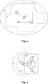
- a manipulator system 10 which comprises laser scanners 2 in order to monitor a protective field 3.
- the protective field 3 has a complex contour.
- a projection device comprising a projector 4 is provided on the manipulator system 10.
- the projector 4 throws a light projection 5 onto the floor.
- protective field information is signaled to the environment.
- This light projection 5 is larger than the protective field 3 and identifies an area on the floor which includes the protective field 3.
- the light projection is greatly simplified in order to be able to better communicate the protective field.
- the person skilled in the art understands that the shape of the light projection or the degree of simplification of the protective field to be communicated can be variably adapted.
- the protective field 3 can adapt its shape dynamically during the operation of the manipulator system 10. A worker thus recognizes that he should not enter the area marked by the light projection 5, as this could lead to a protective field violation.
- a locally stationary manipulator system 10 which comprises a manipulator 11 which is movable.
- a protective field 3 is locally monitored here by means of a monitoring device 2 in order to prevent collisions between the manipulator 11 and an object penetrating into the protective field 3.
- a projection device comprising a projector 4 is used to generate a light projection 5 which, as in FIG Figure 1 covers a larger area than the protective field 3 monitored by means of the monitoring device 2. In this way, a worker can be signaled which area he should not approach.
- the light projections 5 can only be formed by a line which can extend around the manipulator system 10, but does not have to form a closed contour.
- the light projection 5 can advantageously also be partially or completely illuminated by the projection device.
- manipulator system 10 can be stationary or movable.
- driverless transport systems are described, which are also applicable to stationary manipulator systems.
- the driverless transport systems can also be part of the manipulator system 10 of the Figure 1 or 2 be.
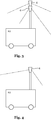
- a driverless transport system 12 which comprises two projectors 4.
- the projectors 4 are provided at an elevated position and can produce various light projections on the ground. By selectively driving one of the projectors 4 it can be controlled which of the corresponding two different light projections is to be projected.
- both projectors 4 can project simultaneously and jointly signal protective field information to the environment.
- a driverless transport system 12 is shown, with a projector 4 provided at an elevated level.
- This projector 4 can project various patterns. The light or the pattern is projected directly onto the floor.
- the projector4 can variably adapt its projection pattern.
- the transport system 12 can therefore be used very flexibly, since, depending on the application, an individual projection pattern can be generated in order to signal the respective protective field information to the environment.
- a driverless transport system 12 is shown, with three projectors 4 which are movably arranged. Since the projectors 4 are movably mounted, the Position of the light projection can be changed.
- the projectors 4 can be rotatably and / or pivotably mounted. By changing the angle of the projectors 4 relative to the driverless transport system 10, the position of the light projection on the floor can be varied, and thus the projection can be changed. Furthermore, by moving one or more projectors 4, a specific pattern can be displayed on the floor.
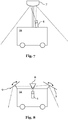
- a driverless transport system 12 in which a projector 4 is provided on a rotatable plate 6.
- a projector can be provided on the system in a rotatable manner.
- the projector 4 generates a visible point projection onto the floor.
- the projector 4 can be permanently mounted so that a circle is displayed on the floor by rotating the projector 4.
- a plurality of such projectors can also be provided on the plate 6. By switching between these projectors, different diameters can advantageously be displayed on the floor.
- the projector 4 can also be mounted pivotably so that a desired pattern can be displayed by a mechanical guide. By changing the position of the guide, the size of the pattern can be changed.
- the angle of the projector 4 can be actuated, for example electrically, pneumatically or hydraulically. By means of a corresponding control signal, the angle of the projector 4 can be adjusted as a function of the angle of the rotatable plate 6, so that a desired projection pattern is projected onto the floor.
- a driverless transport system 12 on which a lens 7 is mounted in an elevated position.
- a mirror and / or a prism can also be used.
- a projector 4 provided on the transport system 12 is aimed at this lens 7.
- the lens reflects or refracts the light emitted by the projector 4 in such a way that a desired light projection is displayed on the floor.
- the lens 7 can be moved in order to change the position of the light projection.
- the breaking property of the lens can also be varied in order to project a desired pattern at a desired location in the surroundings.
- the projection generated can also be varied by varying the radiation emitted by the projector 4.
- several projectors 4 can also be directed at the lens 7 in order to generate a desired projection pattern.
- a driverless transport system 12 in which the light emitted by a projector 4 is reflected by a plurality of mirrors 8, 9 in order to display the desired light projection on the floor.
- the outer mirrors 9 can be movable in order to control the light projection.
- a driverless transport system 12 which moves to the right in the figure.
- projectors which here include laser sources, are controlled in such a way that different patterns are displayed in front of and to the side of the driverless transport system 12. By displaying lines, it can be signaled directly that these areas should not be entered.
- the light projection 5 on the floor here also includes symbols which make it clear to a worker that the area marked by the light projection 5 should not be entered.
- the acoustic signals can also be output if an optical signaling of information is not possible, or if a source of error is not possible was remedied within a predefined time interval after optical signaling.
- Additional information can also be displayed through the projection.
- the color of the projections can be changed if the protective field is violated.
- textual and / or symbolic information can also be displayed, or an upcoming change in the protective field can be displayed in order to inform an HRC environment accordingly.
- the areas to be avoided by people can be clearly identified. Hatching and standardized warning symbols can be mapped directly to the decisive position using powerful light emitters such as lasers.
- a meaningful current flow of the laser source can preferably be monitored in order to detect a defect.
Landscapes
- Engineering & Computer Science (AREA)
- General Engineering & Computer Science (AREA)
- Mechanical Engineering (AREA)
- Robotics (AREA)
- Manufacturing & Machinery (AREA)
- Quality & Reliability (AREA)
- Physics & Mathematics (AREA)
- General Physics & Mathematics (AREA)
- Automation & Control Theory (AREA)
- Manipulator (AREA)
- Control Of Position, Course, Altitude, Or Attitude Of Moving Bodies (AREA)
Claims (14)
- Système de transport sans conducteur (12) comprenantun équipement de surveillance (2) qui est agencé pour surveiller un champ de protection (3) du système de transport (1, 12), caractérisé en ce que le système de transport comprend, en plus de l'équipement de surveillance, un dispositif de projection (4) qui est agencé pour projeter une information de champ de protection dans l'environnement du système de transport (1, 12),le dispositif de projection (4) étant agencé pour générer une projection lumineuse (5) dans l'environnement du système de transport (1, 12) afin de projeter l'information de champ de protection de manière visible,l'information de champ de protection incluant de l'information sur un champ de protection ultérieur, lequel sert de base à une surveillance ultérieure du système de transport (1, 12) à un moment ultérieur.
- Système de transport selon la revendication 1, l'équipement de surveillance (2) incluant un moyen de détection d'objets dans un champ de protection (3), le moyen incluant de préférence un dispositif à laser, à caméra, à radar, à ultrasons, à infrarouges et/ou à lidar.
- Système de transport (1, 12) selon une des revendications 1 à 2, la projection lumineuse (5) étant orientée au moins en partie vers le sol de l'environnement.
- Système de transport (1, 12) selon la revendication 3, un contour de la projection lumineuse (5) étant rond, ovale, circulaire, elliptique ou rectangulaire, et/ou le contour de la projection lumineuse (5) étant différent d'un contour du champ de protection (3).
- Système de transport (1, 12) selon la revendication 3 ou 4, la projection lumineuse (5) incluant un codage et en particulier un motif et/ou un symbole correspondant à l'information de champ de protection.
- Système de transport (1, 12) selon une des revendications 3 à 5, une extension horizontale de la projection lumineuse (5) correspondant au moins à une extension horizontale du champ de protection (3).
- Système de transport (1, 12) selon une des revendications 3 à 6, la projection lumineuse (5) couvrant sur un plan horizontal au moins une zone couverte par le champ de protection (3), et de préférence sur le plan horizontal une zone supérieure à la zone couverte par le champ de protection (3), la zone supérieure correspondant de préférence à 101 % jusqu'à 150 %, plus préférentiellement à 102 % jusqu'à 140 %, plus préférentiellement de 103 % jusqu'à 130 %, plus préférentiellement de 104 % jusqu'à 120 % et le plus préférentiellement de 105 % jusqu'à 110 % de la zone couverte par le champ de protection (3).
- Système de transport (1, 12) selon une des revendications 1 à 7, le dispositif de projection (4) incluant au moins un projecteur (4) et un moyen de déviation (7, 8, 9) qui est fourni séparément du projecteur (4) et qui dirige la lumière émise par le projecteur (4) vers l'environnement, le moyen de déviation (7, 8, 9) incluant de préférence un miroir (8, 9) et/ou une lentille (7), le moyen de déviation (7, 8, 9) étant en outre disposé de préférence de manière mobile.
- Système de transport (1, 12) selon une des revendications 1 à 8, le dispositif de projection (4) incluant au moins un projecteur (4) qui est fourni de manière mobile et de préférence tournante sur le système de transport (1, 12).
- Système de transport (1, 12) selon une des revendications 1 à 9, le dispositif de projection (4) incluant au moins un projecteur (4) et au moins un masque, le masque étant éclairé par le projecteur (4) et définissant un motif de projection.
- Procédé de fonctionnement d'un système de transport (1, 12) et en particulier d'un système de transport (1, 12) selon une des revendications 1 à 10, le système de transport (1, 12) incluant un équipement de surveillance (2) et en outre un dispositif de projection (4), le procédé consistant à :surveiller un champ de protection (3) du système de transport (1, 12) au moyen de l'équipement de surveillance (2) ; et àprojeter une information de champ de protection dans l'environnement du système de transport (1, 12) au moyen du dispositif de projection (4), y compris à projeter une projection lumineuse (5) dans l'environnement du système de transport,l'information de champ de protection incluant de l'information sur un champ de protection ultérieur, lequel sert de base à une surveillance ultérieure du système de transport (1, 12) à un moment ultérieur.
- Système de transport (1, 12) ou procédé selon une des revendications 1 à 11, la projection d'information de champ de protection s'effectuant sur la base d'au moins une des grandeurs suivantes et le dispositif de projection étant agencé pour réaliser l'information de champ de protection sur la base d'une des grandeurs suivantes :- une forme et/ou une variation de forme du champ de protection (3) ;- une grandeur et/ou une variation de grandeur du champ de protection (3) ;- un état et/ou une variation d'état du système de transport (1, 12) ;- une vitesse et/ou une accélération du système de transport (1, 12) ;- une orientation et/ou une réorientation du système de transport (1, 12) ;- une planification de trajectoire du système de transport (1, 12) ;- un mode de fonctionnement du système de transport (1, 12) ;- une carte d'environnement.
- Système de transport (1, 12) ou procédé selon une des revendications 1 à 12, le dispositif de projection étant agencé pour adapter la projection d'informations de champ de protection de manière quasi continue pendant le fonctionnement du système de transport (1, 12) et de préférence dans chaque cadence d'interpolation du système de transport (1, 12), et le procédé adaptant la projection d'information de champ de protection de manière quasi continue pendant le fonctionnement du système de transport (1, 12) et de préférence dans chaque cadence d'interpolation du système de transport (1, 12).
- Système de transport (1, 12) ou procédé selon une des revendications 1 à 13, le dispositif de projection et l'équipement de surveillance étant disposés de manière spatialement séparée, plus préférentiellement le dispositif de projection étant prévu dans une position surélevée par rapport à l'équipement de surveillance.
Applications Claiming Priority (2)
| Application Number | Priority Date | Filing Date | Title |
|---|---|---|---|
| DE102015224309.5A DE102015224309A1 (de) | 2015-12-04 | 2015-12-04 | Darstellung variabler Schutzfelder |
| PCT/EP2016/079033 WO2017093197A1 (fr) | 2015-12-04 | 2016-11-28 | Représentation de zones protégées variables |
Publications (2)
| Publication Number | Publication Date |
|---|---|
| EP3383595A1 EP3383595A1 (fr) | 2018-10-10 |
| EP3383595B1 true EP3383595B1 (fr) | 2021-09-01 |
Family
ID=57442673
Family Applications (1)
| Application Number | Title | Priority Date | Filing Date |
|---|---|---|---|
| EP16804748.8A Revoked EP3383595B1 (fr) | 2015-12-04 | 2016-11-28 | Représentation de zones protégées variables |
Country Status (4)
| Country | Link |
|---|---|
| EP (1) | EP3383595B1 (fr) |
| CN (1) | CN108290292B (fr) |
| DE (1) | DE102015224309A1 (fr) |
| WO (1) | WO2017093197A1 (fr) |
Families Citing this family (11)
| Publication number | Priority date | Publication date | Assignee | Title |
|---|---|---|---|---|
| WO2018213955A1 (fr) * | 2017-05-21 | 2018-11-29 | 李仁涛 | Appareil et procédé d'évitement d'obstacle de voiture sans conducteur |
| CN107150342B (zh) * | 2017-07-18 | 2020-04-28 | 广东工业大学 | 一种工业机器人及其工业机器人避障系统 |
| EP3431228A1 (fr) * | 2017-07-21 | 2019-01-23 | Siemens Aktiengesellschaft | Procédé et agencement de surveillance d'une zone de la pénétration d'un obstacle |
| DE102017117545A1 (de) * | 2017-08-02 | 2019-02-07 | Jungheinrich Aktiengesellschaft | Verfahren zur Überwachung des Fahrwegs eines Flurförderzeuges sowie ein Flurförderzeug |
| DE102018100758A1 (de) | 2018-01-15 | 2019-07-18 | Jungheinrich Aktiengesellschaft | Verfahren zur Steuerung eines Flurförderzeugs sowie ein System aus einer übergeordneten Steuereinheit und einem Fluförderzeug |
| EP3588228A1 (fr) * | 2018-06-27 | 2020-01-01 | Siemens Aktiengesellschaft | Véhicule de transport sans conducteur, dispositif et procédé d'affichage d'une réalité augmentée |
| US11258987B2 (en) | 2018-09-21 | 2022-02-22 | Microsoft Technology Licensing, Llc | Anti-collision and motion control systems and methods |
| CN110014440A (zh) * | 2019-05-24 | 2019-07-16 | 北京深醒科技有限公司 | 一种地下车库安防巡检机器人 |
| US11815598B2 (en) | 2019-06-10 | 2023-11-14 | Microsoft Technology Licensing, Llc | Anti-collision and motion monitoring, control, and alerting systems and methods |
| DE102022104219A1 (de) | 2022-02-23 | 2023-08-24 | Bayerische Motoren Werke Aktiengesellschaft | Fahrerloses Transportfahrzeug |
| DE102023102457A1 (de) | 2023-02-01 | 2024-08-01 | Bayerische Motoren Werke Aktiengesellschaft | Fahrerloses Transportsystem |
Citations (8)
| Publication number | Priority date | Publication date | Assignee | Title |
|---|---|---|---|---|
| DE10240227A1 (de) | 2002-08-28 | 2004-03-11 | Daimlerchrysler Ag | Verfahren und Vorrichtung zum Betrieb einer Anzeigeeinrichtung an einer Arbeitsmaschine |
| US20060041333A1 (en) | 2004-05-17 | 2006-02-23 | Takashi Anezaki | Robot |
| WO2009063318A1 (fr) | 2007-11-16 | 2009-05-22 | Toyota Jidosha Kabushiki Kaisha | Robot mobile et procédé d'indication de zone dangereuse de robot mobile |
| DE102010007027A1 (de) | 2010-02-05 | 2011-08-11 | KUKA Laboratories GmbH, 86165 | Verfahren und Vorrichtung zur Überwachung eines Manipulatorraumes |
| EP2380709A2 (fr) | 2010-04-22 | 2011-10-26 | Sick AG | Dispositif de sécurité 3D et procédé de sécurisation et de commande d'au moins une machine |
| US20120182155A1 (en) | 2010-01-25 | 2012-07-19 | Taichi Sato | Danger presentation device, danger presentation system, danger presentation method and program |
| DE102013215409A1 (de) | 2013-08-06 | 2015-02-12 | Robert Bosch Gmbh | Projektionseinheit für eine selbsttätig mobile Plattform, Transportroboter und Verfahren zum Betrieb einer selbsttätig mobilen Plattform |
| DE202015105376U1 (de) | 2015-10-12 | 2015-10-19 | Sick Ag | 3D-Kamera zur Aufnahme von dreidimensionalen Bildern |
Family Cites Families (9)
| Publication number | Priority date | Publication date | Assignee | Title |
|---|---|---|---|---|
| US6317953B1 (en) * | 1981-05-11 | 2001-11-20 | Lmi-Diffracto | Vision target based assembly |
| JPH08272424A (ja) * | 1995-04-03 | 1996-10-18 | Amada Metrecs Co Ltd | 産業用ロボットの数値制御装置 |
| US7440620B1 (en) * | 2004-05-21 | 2008-10-21 | Rockwell Automation B.V. | Infrared safety systems and methods |
| JP4623501B2 (ja) * | 2005-02-18 | 2011-02-02 | タカタ株式会社 | 検知システム、報知装置、駆動装置、車両 |
| DE102006002960A1 (de) * | 2006-01-21 | 2007-07-26 | Linde Ag | Flurförderzeug mit einer optischen Warneinrichtung |
| WO2011128117A2 (fr) * | 2010-04-16 | 2011-10-20 | Fraunhofer-Gesellschaft Zur Förderung Der Angewandten Forschung E.V. . | Dispositif de surveillance d'au moins une zone de sécurité tridimensionnelle |
| US9230419B2 (en) * | 2010-07-27 | 2016-01-05 | Rite-Hite Holding Corporation | Methods and apparatus to detect and warn proximate entities of interest |
| US9744672B2 (en) * | 2011-11-16 | 2017-08-29 | University Of South Florida | Systems and methods for communicating robot intentions to human beings |
| EP2731087B1 (fr) * | 2012-11-12 | 2015-01-14 | Axis AB | Caméra et procédé de surveillance |
-
2015
- 2015-12-04 DE DE102015224309.5A patent/DE102015224309A1/de active Pending
-
2016
- 2016-11-28 WO PCT/EP2016/079033 patent/WO2017093197A1/fr active Application Filing
- 2016-11-28 EP EP16804748.8A patent/EP3383595B1/fr not_active Revoked
- 2016-11-28 CN CN201680071051.0A patent/CN108290292B/zh active Active
Patent Citations (8)
| Publication number | Priority date | Publication date | Assignee | Title |
|---|---|---|---|---|
| DE10240227A1 (de) | 2002-08-28 | 2004-03-11 | Daimlerchrysler Ag | Verfahren und Vorrichtung zum Betrieb einer Anzeigeeinrichtung an einer Arbeitsmaschine |
| US20060041333A1 (en) | 2004-05-17 | 2006-02-23 | Takashi Anezaki | Robot |
| WO2009063318A1 (fr) | 2007-11-16 | 2009-05-22 | Toyota Jidosha Kabushiki Kaisha | Robot mobile et procédé d'indication de zone dangereuse de robot mobile |
| US20120182155A1 (en) | 2010-01-25 | 2012-07-19 | Taichi Sato | Danger presentation device, danger presentation system, danger presentation method and program |
| DE102010007027A1 (de) | 2010-02-05 | 2011-08-11 | KUKA Laboratories GmbH, 86165 | Verfahren und Vorrichtung zur Überwachung eines Manipulatorraumes |
| EP2380709A2 (fr) | 2010-04-22 | 2011-10-26 | Sick AG | Dispositif de sécurité 3D et procédé de sécurisation et de commande d'au moins une machine |
| DE102013215409A1 (de) | 2013-08-06 | 2015-02-12 | Robert Bosch Gmbh | Projektionseinheit für eine selbsttätig mobile Plattform, Transportroboter und Verfahren zum Betrieb einer selbsttätig mobilen Plattform |
| DE202015105376U1 (de) | 2015-10-12 | 2015-10-19 | Sick Ag | 3D-Kamera zur Aufnahme von dreidimensionalen Bildern |
Non-Patent Citations (1)
| Title |
|---|
| CHADALAVADA RAVI TEJA; ANDREASSON HENRIK; KRUG ROBERT; LILIENTHAL ACHIM J.: "That’s on my mind! robot to human intention communication through on-board projection on shared floor space", 2015 EUROPEAN CONFERENCE ON MOBILE ROBOTS (ECMR), IEEE, 2 September 2015 (2015-09-02), pages 1 - 6, XP032860824, DOI: 10.1109/ECMR.2015.7403771 |
Also Published As
| Publication number | Publication date |
|---|---|
| WO2017093197A1 (fr) | 2017-06-08 |
| DE102015224309A1 (de) | 2017-06-08 |
| CN108290292A (zh) | 2018-07-17 |
| EP3383595A1 (fr) | 2018-10-10 |
| CN108290292B (zh) | 2021-09-03 |
Similar Documents
| Publication | Publication Date | Title |
|---|---|---|
| EP3383595B1 (fr) | Représentation de zones protégées variables | |
| EP3365142B1 (fr) | Ajustement du champ de protection d'un système de manipulation | |
| EP3490741B1 (fr) | Machine d'usinage de pièces et son procédé de fonctionnement | |
| EP3140087B1 (fr) | Procédé d'alerte et système robotisé | |
| EP3663252B1 (fr) | Procédé pour faire fonctionner un agv et système intralogistique avec un agv | |
| EP3420422B1 (fr) | Appareil de commande pour un manipulateur | |
| EP1788467B1 (fr) | Dispositif de protection | |
| EP2053538B1 (fr) | Protection d'une zone de surveillance et support visuel d'un usinage automatisé | |
| DE202014010054U1 (de) | Protektofon - eine kognitive Sicherheitsfunktion | |
| EP3791105B1 (fr) | Dispositif et procédé pour sécuriser un appareil mobile à commande mécanique ou automatique et carreau de capteurs | |
| EP3683183B1 (fr) | Procédé de fonctionnement d'un chariot de manutention ainsi que chariot de manutention et système intralogistique | |
| EP3865257A1 (fr) | Équipement et procédés de surveillance et de commande d'un système de travail technique | |
| DE102016001201B4 (de) | Kraftfahrzeug | |
| WO2004025385A1 (fr) | Procede et dispositif pour faire fonctionner un dispositif indicateur sur une machine-outil | |
| DE102019202734A1 (de) | Verfahren zur Kollisionsvermeidung und Kollisionsvermeidungssystem | |
| EP3936962A1 (fr) | Ajustement de la surveillance protégée contre les erreurs dans une installation d'automatisation industrielle | |
| DE102010047641A1 (de) | Steuerung eines Roboters | |
| DE102014219538A1 (de) | Verfahren zum Betreiben von mobilen Plattformen und mobile Plattform | |
| DE102016224693B4 (de) | Vorrichtungen und Verfahren zum Koppeln eines tragbaren Handbediengeräts mit einem Manipulator | |
| DE102013020137A1 (de) | Arbeitsstation, insbesondere zum Herstellen eines Kraftwagens, sowie Verfahren zum Betreiben einer Arbeitsstation | |
| EP4158435B1 (fr) | Procédé de pilotage automatisé d'un véhicule à moteur et appareil mobile de transmission de signal pour la transmission de signal sans fil avec un véhicule à moteur commandable automatiquement | |
| EP4253306A1 (fr) | Chariot de manutention doté d'un capteur et d'un dispositif de traitement de données | |
| DE102021131028A1 (de) | Verbesserte Mensch-Roboter-Interaktion durch erweiterte Realität | |
| EP3757443A1 (fr) | Élément de surveillance et procédé de sécurisation de zones dangereuses | |
| EP3959047A1 (fr) | Procédé et système de surveillance d'un agencement de robots |
Legal Events
| Date | Code | Title | Description |
|---|---|---|---|
| STAA | Information on the status of an ep patent application or granted ep patent |
Free format text: STATUS: UNKNOWN |
|
| STAA | Information on the status of an ep patent application or granted ep patent |
Free format text: STATUS: THE INTERNATIONAL PUBLICATION HAS BEEN MADE |
|
| PUAI | Public reference made under article 153(3) epc to a published international application that has entered the european phase |
Free format text: ORIGINAL CODE: 0009012 |
|
| STAA | Information on the status of an ep patent application or granted ep patent |
Free format text: STATUS: REQUEST FOR EXAMINATION WAS MADE |
|
| 17P | Request for examination filed |
Effective date: 20180621 |
|
| AK | Designated contracting states |
Kind code of ref document: A1 Designated state(s): AL AT BE BG CH CY CZ DE DK EE ES FI FR GB GR HR HU IE IS IT LI LT LU LV MC MK MT NL NO PL PT RO RS SE SI SK SM TR |
|
| AX | Request for extension of the european patent |
Extension state: BA ME |
|
| DAV | Request for validation of the european patent (deleted) | ||
| DAX | Request for extension of the european patent (deleted) | ||
| STAA | Information on the status of an ep patent application or granted ep patent |
Free format text: STATUS: EXAMINATION IS IN PROGRESS |
|
| 17Q | First examination report despatched |
Effective date: 20201119 |
|
| GRAP | Despatch of communication of intention to grant a patent |
Free format text: ORIGINAL CODE: EPIDOSNIGR1 |
|
| STAA | Information on the status of an ep patent application or granted ep patent |
Free format text: STATUS: GRANT OF PATENT IS INTENDED |
|
| INTG | Intention to grant announced |
Effective date: 20210518 |
|
| GRAS | Grant fee paid |
Free format text: ORIGINAL CODE: EPIDOSNIGR3 |
|
| GRAA | (expected) grant |
Free format text: ORIGINAL CODE: 0009210 |
|
| STAA | Information on the status of an ep patent application or granted ep patent |
Free format text: STATUS: THE PATENT HAS BEEN GRANTED |
|
| AK | Designated contracting states |
Kind code of ref document: B1 Designated state(s): AL AT BE BG CH CY CZ DE DK EE ES FI FR GB GR HR HU IE IS IT LI LT LU LV MC MK MT NL NO PL PT RO RS SE SI SK SM TR |
|
| REG | Reference to a national code |
Ref country code: GB Ref legal event code: FG4D Free format text: NOT ENGLISH |
|
| REG | Reference to a national code |
Ref country code: CH Ref legal event code: EP Ref country code: AT Ref legal event code: REF Ref document number: 1425736 Country of ref document: AT Kind code of ref document: T Effective date: 20210915 |
|
| REG | Reference to a national code |
Ref country code: DE Ref legal event code: R096 Ref document number: 502016013768 Country of ref document: DE |
|
| REG | Reference to a national code |
Ref country code: IE Ref legal event code: FG4D Free format text: LANGUAGE OF EP DOCUMENT: GERMAN |
|
| REG | Reference to a national code |
Ref country code: LT Ref legal event code: MG9D |
|
| REG | Reference to a national code |
Ref country code: NL Ref legal event code: MP Effective date: 20210901 |
|
| PG25 | Lapsed in a contracting state [announced via postgrant information from national office to epo] |
Ref country code: LT Free format text: LAPSE BECAUSE OF FAILURE TO SUBMIT A TRANSLATION OF THE DESCRIPTION OR TO PAY THE FEE WITHIN THE PRESCRIBED TIME-LIMIT Effective date: 20210901 Ref country code: BG Free format text: LAPSE BECAUSE OF FAILURE TO SUBMIT A TRANSLATION OF THE DESCRIPTION OR TO PAY THE FEE WITHIN THE PRESCRIBED TIME-LIMIT Effective date: 20211201 Ref country code: HR Free format text: LAPSE BECAUSE OF FAILURE TO SUBMIT A TRANSLATION OF THE DESCRIPTION OR TO PAY THE FEE WITHIN THE PRESCRIBED TIME-LIMIT Effective date: 20210901 Ref country code: ES Free format text: LAPSE BECAUSE OF FAILURE TO SUBMIT A TRANSLATION OF THE DESCRIPTION OR TO PAY THE FEE WITHIN THE PRESCRIBED TIME-LIMIT Effective date: 20210901 Ref country code: FI Free format text: LAPSE BECAUSE OF FAILURE TO SUBMIT A TRANSLATION OF THE DESCRIPTION OR TO PAY THE FEE WITHIN THE PRESCRIBED TIME-LIMIT Effective date: 20210901 Ref country code: NO Free format text: LAPSE BECAUSE OF FAILURE TO SUBMIT A TRANSLATION OF THE DESCRIPTION OR TO PAY THE FEE WITHIN THE PRESCRIBED TIME-LIMIT Effective date: 20211201 Ref country code: RS Free format text: LAPSE BECAUSE OF FAILURE TO SUBMIT A TRANSLATION OF THE DESCRIPTION OR TO PAY THE FEE WITHIN THE PRESCRIBED TIME-LIMIT Effective date: 20210901 Ref country code: SE Free format text: LAPSE BECAUSE OF FAILURE TO SUBMIT A TRANSLATION OF THE DESCRIPTION OR TO PAY THE FEE WITHIN THE PRESCRIBED TIME-LIMIT Effective date: 20210901 |
|
| PG25 | Lapsed in a contracting state [announced via postgrant information from national office to epo] |
Ref country code: PL Free format text: LAPSE BECAUSE OF FAILURE TO SUBMIT A TRANSLATION OF THE DESCRIPTION OR TO PAY THE FEE WITHIN THE PRESCRIBED TIME-LIMIT Effective date: 20210901 Ref country code: LV Free format text: LAPSE BECAUSE OF FAILURE TO SUBMIT A TRANSLATION OF THE DESCRIPTION OR TO PAY THE FEE WITHIN THE PRESCRIBED TIME-LIMIT Effective date: 20210901 Ref country code: GR Free format text: LAPSE BECAUSE OF FAILURE TO SUBMIT A TRANSLATION OF THE DESCRIPTION OR TO PAY THE FEE WITHIN THE PRESCRIBED TIME-LIMIT Effective date: 20211202 |
|
| REG | Reference to a national code |
Ref country code: DE Ref legal event code: R026 Ref document number: 502016013768 Country of ref document: DE |
|
| PLBI | Opposition filed |
Free format text: ORIGINAL CODE: 0009260 |
|
| PG25 | Lapsed in a contracting state [announced via postgrant information from national office to epo] |
Ref country code: IS Free format text: LAPSE BECAUSE OF FAILURE TO SUBMIT A TRANSLATION OF THE DESCRIPTION OR TO PAY THE FEE WITHIN THE PRESCRIBED TIME-LIMIT Effective date: 20220101 Ref country code: SM Free format text: LAPSE BECAUSE OF FAILURE TO SUBMIT A TRANSLATION OF THE DESCRIPTION OR TO PAY THE FEE WITHIN THE PRESCRIBED TIME-LIMIT Effective date: 20210901 Ref country code: SK Free format text: LAPSE BECAUSE OF FAILURE TO SUBMIT A TRANSLATION OF THE DESCRIPTION OR TO PAY THE FEE WITHIN THE PRESCRIBED TIME-LIMIT Effective date: 20210901 Ref country code: RO Free format text: LAPSE BECAUSE OF FAILURE TO SUBMIT A TRANSLATION OF THE DESCRIPTION OR TO PAY THE FEE WITHIN THE PRESCRIBED TIME-LIMIT Effective date: 20210901 Ref country code: PT Free format text: LAPSE BECAUSE OF FAILURE TO SUBMIT A TRANSLATION OF THE DESCRIPTION OR TO PAY THE FEE WITHIN THE PRESCRIBED TIME-LIMIT Effective date: 20220103 Ref country code: NL Free format text: LAPSE BECAUSE OF FAILURE TO SUBMIT A TRANSLATION OF THE DESCRIPTION OR TO PAY THE FEE WITHIN THE PRESCRIBED TIME-LIMIT Effective date: 20210901 Ref country code: EE Free format text: LAPSE BECAUSE OF FAILURE TO SUBMIT A TRANSLATION OF THE DESCRIPTION OR TO PAY THE FEE WITHIN THE PRESCRIBED TIME-LIMIT Effective date: 20210901 Ref country code: CZ Free format text: LAPSE BECAUSE OF FAILURE TO SUBMIT A TRANSLATION OF THE DESCRIPTION OR TO PAY THE FEE WITHIN THE PRESCRIBED TIME-LIMIT Effective date: 20210901 Ref country code: AL Free format text: LAPSE BECAUSE OF FAILURE TO SUBMIT A TRANSLATION OF THE DESCRIPTION OR TO PAY THE FEE WITHIN THE PRESCRIBED TIME-LIMIT Effective date: 20210901 |
|
| PLBI | Opposition filed |
Free format text: ORIGINAL CODE: 0009260 |
|
| PLAX | Notice of opposition and request to file observation + time limit sent |
Free format text: ORIGINAL CODE: EPIDOSNOBS2 |
|
| 26 | Opposition filed |
Opponent name: SICK AG Effective date: 20220520 |
|
| PG25 | Lapsed in a contracting state [announced via postgrant information from national office to epo] |
Ref country code: MC Free format text: LAPSE BECAUSE OF FAILURE TO SUBMIT A TRANSLATION OF THE DESCRIPTION OR TO PAY THE FEE WITHIN THE PRESCRIBED TIME-LIMIT Effective date: 20210901 |
|
| 26 | Opposition filed |
Opponent name: DEMATIC GMBH Effective date: 20220531 |
|
| PLAB | Opposition data, opponent's data or that of the opponent's representative modified |
Free format text: ORIGINAL CODE: 0009299OPPO |
|
| PG25 | Lapsed in a contracting state [announced via postgrant information from national office to epo] |
Ref country code: LU Free format text: LAPSE BECAUSE OF NON-PAYMENT OF DUE FEES Effective date: 20211128 Ref country code: IT Free format text: LAPSE BECAUSE OF FAILURE TO SUBMIT A TRANSLATION OF THE DESCRIPTION OR TO PAY THE FEE WITHIN THE PRESCRIBED TIME-LIMIT Effective date: 20210901 Ref country code: DK Free format text: LAPSE BECAUSE OF FAILURE TO SUBMIT A TRANSLATION OF THE DESCRIPTION OR TO PAY THE FEE WITHIN THE PRESCRIBED TIME-LIMIT Effective date: 20210901 Ref country code: BE Free format text: LAPSE BECAUSE OF NON-PAYMENT OF DUE FEES Effective date: 20211130 |
|
| REG | Reference to a national code |
Ref country code: BE Ref legal event code: MM Effective date: 20211130 |
|
| R26 | Opposition filed (corrected) |
Opponent name: DEMATIC GMBH Effective date: 20220531 |
|
| PG25 | Lapsed in a contracting state [announced via postgrant information from national office to epo] |
Ref country code: SI Free format text: LAPSE BECAUSE OF FAILURE TO SUBMIT A TRANSLATION OF THE DESCRIPTION OR TO PAY THE FEE WITHIN THE PRESCRIBED TIME-LIMIT Effective date: 20210901 |
|
| PLBB | Reply of patent proprietor to notice(s) of opposition received |
Free format text: ORIGINAL CODE: EPIDOSNOBS3 |
|
| PG25 | Lapsed in a contracting state [announced via postgrant information from national office to epo] |
Ref country code: IE Free format text: LAPSE BECAUSE OF NON-PAYMENT OF DUE FEES Effective date: 20211128 |
|
| PLAB | Opposition data, opponent's data or that of the opponent's representative modified |
Free format text: ORIGINAL CODE: 0009299OPPO |
|
| R26 | Opposition filed (corrected) |
Opponent name: SICK AG Effective date: 20220520 |
|
| PG25 | Lapsed in a contracting state [announced via postgrant information from national office to epo] |
Ref country code: HU Free format text: LAPSE BECAUSE OF FAILURE TO SUBMIT A TRANSLATION OF THE DESCRIPTION OR TO PAY THE FEE WITHIN THE PRESCRIBED TIME-LIMIT; INVALID AB INITIO Effective date: 20161128 |
|
| PG25 | Lapsed in a contracting state [announced via postgrant information from national office to epo] |
Ref country code: CY Free format text: LAPSE BECAUSE OF FAILURE TO SUBMIT A TRANSLATION OF THE DESCRIPTION OR TO PAY THE FEE WITHIN THE PRESCRIBED TIME-LIMIT Effective date: 20210901 |
|
| P01 | Opt-out of the competence of the unified patent court (upc) registered |
Effective date: 20230528 |
|
| PGFP | Annual fee paid to national office [announced via postgrant information from national office to epo] |
Ref country code: FR Payment date: 20230929 Year of fee payment: 8 |
|
| PGFP | Annual fee paid to national office [announced via postgrant information from national office to epo] |
Ref country code: GB Payment date: 20231006 Year of fee payment: 8 |
|
| PGFP | Annual fee paid to national office [announced via postgrant information from national office to epo] |
Ref country code: DE Payment date: 20231003 Year of fee payment: 8 Ref country code: CH Payment date: 20231202 Year of fee payment: 8 Ref country code: AT Payment date: 20231025 Year of fee payment: 8 |
|
| RDAF | Communication despatched that patent is revoked |
Free format text: ORIGINAL CODE: EPIDOSNREV1 |
|
| REG | Reference to a national code |
Ref country code: DE Ref legal event code: R103 Ref document number: 502016013768 Country of ref document: DE Ref country code: DE Ref legal event code: R064 Ref document number: 502016013768 Country of ref document: DE |
|
| PG25 | Lapsed in a contracting state [announced via postgrant information from national office to epo] |
Ref country code: MK Free format text: LAPSE BECAUSE OF FAILURE TO SUBMIT A TRANSLATION OF THE DESCRIPTION OR TO PAY THE FEE WITHIN THE PRESCRIBED TIME-LIMIT Effective date: 20210901 |
|
| RDAG | Patent revoked |
Free format text: ORIGINAL CODE: 0009271 |
|
| STAA | Information on the status of an ep patent application or granted ep patent |
Free format text: STATUS: PATENT REVOKED |
|
| REG | Reference to a national code |
Ref country code: CH Ref legal event code: PL |
|
| 27W | Patent revoked |
Effective date: 20240202 |
|
| GBPR | Gb: patent revoked under art. 102 of the ep convention designating the uk as contracting state |
Effective date: 20240202 |
|
| REG | Reference to a national code |
Ref country code: AT Ref legal event code: MA03 Ref document number: 1425736 Country of ref document: AT Kind code of ref document: T Effective date: 20240202 |
|
| PG25 | Lapsed in a contracting state [announced via postgrant information from national office to epo] |
Ref country code: MT Free format text: LAPSE BECAUSE OF FAILURE TO SUBMIT A TRANSLATION OF THE DESCRIPTION OR TO PAY THE FEE WITHIN THE PRESCRIBED TIME-LIMIT Effective date: 20210901 |