EP3140087B1 - Procédé d'alerte et système robotisé - Google Patents
Procédé d'alerte et système robotisé Download PDFInfo
- Publication number
- EP3140087B1 EP3140087B1 EP14735560.6A EP14735560A EP3140087B1 EP 3140087 B1 EP3140087 B1 EP 3140087B1 EP 14735560 A EP14735560 A EP 14735560A EP 3140087 B1 EP3140087 B1 EP 3140087B1
- Authority
- EP
- European Patent Office
- Prior art keywords
- robot
- segment
- working space
- warning
- floor
- Prior art date
- Legal status (The legal status is an assumption and is not a legal conclusion. Google has not performed a legal analysis and makes no representation as to the accuracy of the status listed.)
- Active
Links
- 238000000034 method Methods 0.000 title claims description 75
- 230000000007 visual effect Effects 0.000 claims description 48
- 230000008569 process Effects 0.000 claims description 10
- 238000004590 computer program Methods 0.000 claims description 8
- 230000006870 function Effects 0.000 claims description 2
- GNFTZDOKVXKIBK-UHFFFAOYSA-N 3-(2-methoxyethoxy)benzohydrazide Chemical compound COCCOC1=CC=CC(C(=O)NN)=C1 GNFTZDOKVXKIBK-UHFFFAOYSA-N 0.000 claims 1
- FGUUSXIOTUKUDN-IBGZPJMESA-N C1(=CC=CC=C1)N1C2=C(NC([C@H](C1)NC=1OC(=NN=1)C1=CC=CC=C1)=O)C=CC=C2 Chemical compound C1(=CC=CC=C1)N1C2=C(NC([C@H](C1)NC=1OC(=NN=1)C1=CC=CC=C1)=O)C=CC=C2 FGUUSXIOTUKUDN-IBGZPJMESA-N 0.000 claims 1
- 230000007246 mechanism Effects 0.000 description 6
- 230000001934 delay Effects 0.000 description 3
- 238000004088 simulation Methods 0.000 description 3
- 238000013459 approach Methods 0.000 description 2
- 230000006399 behavior Effects 0.000 description 2
- 230000001427 coherent effect Effects 0.000 description 2
- 239000003086 colorant Substances 0.000 description 2
- 238000011156 evaluation Methods 0.000 description 2
- 238000004519 manufacturing process Methods 0.000 description 2
- 239000000463 material Substances 0.000 description 2
- 230000000737 periodic effect Effects 0.000 description 2
- 239000000126 substance Substances 0.000 description 2
- 230000001960 triggered effect Effects 0.000 description 2
- 230000003111 delayed effect Effects 0.000 description 1
- 238000001514 detection method Methods 0.000 description 1
- 238000010586 diagram Methods 0.000 description 1
- 230000000694 effects Effects 0.000 description 1
- 239000011521 glass Substances 0.000 description 1
- 231100001261 hazardous Toxicity 0.000 description 1
- 238000005286 illumination Methods 0.000 description 1
- 230000003993 interaction Effects 0.000 description 1
- 238000012544 monitoring process Methods 0.000 description 1
- 230000006855 networking Effects 0.000 description 1
- 229920003229 poly(methyl methacrylate) Polymers 0.000 description 1
- 239000004926 polymethyl methacrylate Substances 0.000 description 1
- 230000007704 transition Effects 0.000 description 1
Images


Classifications
-
- B—PERFORMING OPERATIONS; TRANSPORTING
- B25—HAND TOOLS; PORTABLE POWER-DRIVEN TOOLS; MANIPULATORS
- B25J—MANIPULATORS; CHAMBERS PROVIDED WITH MANIPULATION DEVICES
- B25J19/00—Accessories fitted to manipulators, e.g. for monitoring, for viewing; Safety devices combined with or specially adapted for use in connection with manipulators
- B25J19/06—Safety devices
- B25J19/061—Safety devices with audible signals
-
- B—PERFORMING OPERATIONS; TRANSPORTING
- B25—HAND TOOLS; PORTABLE POWER-DRIVEN TOOLS; MANIPULATORS
- B25J—MANIPULATORS; CHAMBERS PROVIDED WITH MANIPULATION DEVICES
- B25J9/00—Programme-controlled manipulators
- B25J9/16—Programme controls
- B25J9/1674—Programme controls characterised by safety, monitoring, diagnostic
- B25J9/1676—Avoiding collision or forbidden zones
-
- G—PHYSICS
- G08—SIGNALLING
- G08B—SIGNALLING OR CALLING SYSTEMS; ORDER TELEGRAPHS; ALARM SYSTEMS
- G08B21/00—Alarms responsive to a single specified undesired or abnormal condition and not otherwise provided for
- G08B21/02—Alarms for ensuring the safety of persons
-
- G—PHYSICS
- G08—SIGNALLING
- G08B—SIGNALLING OR CALLING SYSTEMS; ORDER TELEGRAPHS; ALARM SYSTEMS
- G08B31/00—Predictive alarm systems characterised by extrapolation or other computation using updated historic data
-
- G—PHYSICS
- G08—SIGNALLING
- G08B—SIGNALLING OR CALLING SYSTEMS; ORDER TELEGRAPHS; ALARM SYSTEMS
- G08B7/00—Signalling systems according to more than one of groups G08B3/00 - G08B6/00; Personal calling systems according to more than one of groups G08B3/00 - G08B6/00
- G08B7/06—Signalling systems according to more than one of groups G08B3/00 - G08B6/00; Personal calling systems according to more than one of groups G08B3/00 - G08B6/00 using electric transmission, e.g. involving audible and visible signalling through the use of sound and light sources
-
- G—PHYSICS
- G05—CONTROLLING; REGULATING
- G05B—CONTROL OR REGULATING SYSTEMS IN GENERAL; FUNCTIONAL ELEMENTS OF SUCH SYSTEMS; MONITORING OR TESTING ARRANGEMENTS FOR SUCH SYSTEMS OR ELEMENTS
- G05B2219/00—Program-control systems
- G05B2219/30—Nc systems
- G05B2219/40—Robotics, robotics mapping to robotics vision
- G05B2219/40196—Projecting light on floor to delimit danger zone around robot
Definitions
- the invention relates to a robot system and a method for warning a person who is in the area of the robot system during operation. Furthermore, the invention relates to a computer program which is suitable for operating a robot system in the sense of the warning method according to the invention.
- a device for monitoring at least one three-dimensional security area which comprises a recording device which is directed onto a surveillance area and serves to record images of a security area.
- the images are checked for whether persons or objects have entered a security area.
- lines or patterns are projected as modulated light with a given frequency.
- the evaluation device detects the shape, size and / or position of the projected lines or patterns.
- a self-propelled robot which is capable of moving along a path while displaying a portion of the path taken to persons in the environment.
- illuminants are attached to the bottom surface, which are coupled to receivers.
- the self-propelled robot has a lighting control that turns on the lights in the ground and illuminates a section of the path taken by the robot.
- the illuminants arranged on the bottom essentially form a chain.
- WO 2009/0633181 A1 discloses a mobile robot configured to indicate danger areas surrounding the robot by light emitting devices.
- the robot is provided with projectors, which are attached to the robot housing are.
- the robot is designed to determine the outlines of a hazardous area and to produce a correspondingly shaped projection on the ground by means of the projectors. In this case, a movement of the robot itself and a movement of a robot part, such as a robot arm, are taken into account.
- WO 2014/036549 A2 discloses a robot having a sensor system for detecting persons in a detection area around the robot.
- the robot comprises a computing unit that is designed to define a danger zone that is at least partially associated with covers the coverage area.
- the robot has an image recognition device by means of which human body parts, such as torso, head or arms, can be recognized. Depending on the detected by the robot body part of a human in the danger zone different security measures, such as reducing the traversing speed of the robot, initiated.
- a warning system for example, includes a colored laser source configured to form a laser beam film on a surface.
- the warning system after JP 05-229784 is attached to a crane that moves a cargo on the crane hook.
- the laser warning system is attached to the crane in such a way that the danger zone below the transported goods is visibly marked.
- a major disadvantage of the known from the prior art warning systems is that in operations often approaches between robots and persons occur in which accidents can only be avoided by the intervention of safety mechanisms of the robot. The robot then comes to a standstill, so that there is a delay in the present work process.
- the invention has for its object to provide a robot system and an associated warning method available, which overcomes the disadvantages outlined in the prior art.
- the method according to the invention serves to warn a person of at least one first robot which is located in a work space.
- the work space is divided into a plurality of work space segments, wherein a work space segment is associated with a floor segment.
- a first step is carried out, in which a robot movement of the at least one robot is predicted.
- the forecasting can be done by means of a time-shifted Simulation or code analysis of a control program of the at least one robot.
- the robot movement is forecast for a working interval.
- the working interval is a selectable period that extends for a selectable period into the future.
- the traversed space determined in the second step comprises an area which is traversed by the main body of the robot, and / or a robot arm, and / or a manipulator mounted on the robot.
- a third method step at least one working space segment is determined which lies at least partially in the space traversed by the robot. It is also determined whether this passage is made in each case in a first or second period.
- the working interval in which the predicted robot movement takes place covers the first and second time periods.
- the first period is preferably a time interval of 0 to 10 seconds in the future, the second period preferably a period of 10 to 20 seconds in the future.
- the third method step makes it possible to predict when, in the course of a predetermined program sequence in the working interval of the at least one first robot, in which working space segments there is a dangerous situation for an operator.
- a first visual warning is output at the floor segment which is assigned to the respective work space segment. If, on the basis of the aforementioned method steps, it is determined that a work space segment is traversed by the robot within the second time period, a second visual warning is output at the associated ground segment.
- the method according to the invention can be based on a time-delayed simulation or a code analysis of the programming of the robot.
- a delayed simulation or a code analysis of a robot programming can be carried out quickly and reliably in a technically simple manner with a low requirement for computing capacity. In doing so, unpredictable external events such as intermittent stalling or deceleration of the robot can be quickly translated into an updated output of visual warnings.
- Programming a robot essentially involves sequential execution of motion commands, thereby further facilitating the predictability of a robot movement.
- the method according to the invention makes it possible to convey a differentiated picture of a potential future dangerous situation in a noticeable manner. This facilitates the anticipation of the robot movement to be performed by persons who can thus adapt their behavior. As a result, an approach of a person to the at least one first robot can be prevented in a simple manner, so that delays in the operating sequence of the at least one first robot are minimized.
- a first transport item is also taken into account, which is moved by the at least one first robot.
- the traversed space is detected, which is crossed by at least one first robot and the first cargo.
- the claimed method thereby becomes more sophisticated in detecting a present situation and allows a more meaningful alerting behavior to a person, thereby improving the safety prevailing in the workspace.
- the first and second visual warnings are each formed as a color signal or as a luminous pattern.
- the first and second visual warning can be embodied, for example, as constant or periodic luminous signals in different colors. It is also possible that the first and second visual warnings each form geometric shapes that are formed on the respective floor segment, such as dot patterns, geometric figures or symbols.
- the light patterns can be constant or variable over time. By a time-varying light pattern, for example, to understand an animation.
- the method according to the invention can output a further differentiated warning to a person who, due to his sense of intent, provides in a simple manner a precise picture of a potential dangerous situation.
- the method according to the invention can additionally determine whether there is a working space segment in at least one third period of time that lies at least partially in the space traveled through. If it is detected that a working space is passed through within the at least one third period, a third visual warning is issued at an associated ground segment.
- a warning method with a consideration of a third time period with the output of a third visual warning makes it possible, in a prevailing situation, to detect and present the scope of the hazard potential in a differentiated manner. This further increases the prevailing safety.
- an acoustic warning can additionally be triggered in a method step in which a first, second or third visual warning is output.
- the triggering of an acoustic warning makes it possible to warn against situations with a high hazard potential. For example, if there are only workspace segments in the workspace, those in the first period of at least one first drive through robot, be warned by means of a warning tone. As a result, operating situations can be avoided in which security mechanisms of the at least one first robot must intervene and cause a delay. This is particularly advantageous in operations where robots are used at a high travel speed.
- the visual warnings and / or the acoustic warning are further formed as a function of at least one process parameter of the at least one robot.
- a visual or audible warning is adapted to the effect that the warning is formed depending on the intensity of the prevailing danger situation. For example, in the presence of a high hazard potential, a changed color tone can be selected, a visual warning can be switched from a constant to a periodic light signal, or a planar visual warning can be converted into a light pattern.
- a process parameter in dependence of which the visual warnings and / or the acoustic warning are adjusted, may be a travel speed of the at least one first robot.
- a quality information of the first cargo can be used as a process parameter.
- the quality information of the first item to be transported indicates whether due to the physical or chemical properties of the first item to be transported therefrom an increased risk can arise for a person.
- Transport goods whose quality information in the sense of the method according to the invention lead to a more intense or clearer warning, for example, containers with chemicals or melt, pointed objects, goods made of hard materials, or goods from visually difficult to perceive materials, such as glass or PMMA.
- a process parameter Information about the nature and / or extent of the security measures of the at least one robot are used, which are triggered when the security mechanisms of the at least one robot intervene. For example, if an intervention of the safety mechanisms leads to a standstill of a complete production line, the first and / or second visual warning or an acoustic warning with increased intensity is output. If an intervention by the security mechanisms leads to a delay without further consequences, the first and / or second visual warning or the acoustic warning is output with reduced intensity.
- a working space segment is not traversed during the working interval of at least a first robot.
- a visual Entwarnsignal is issued in the associated ground segment, which signals a person that during the working interval in the corresponding workspace segment no dangerous situations exists.
- the person in the workroom is conveyed in an obvious way, which areas of the workspace are easily accessible, without having to expect a standstill or a delay of the at least one first robot.
- the efficiency of the method according to the invention is further improved.
- the method according to the invention can be further developed such that the method steps in which a robot movement is predicted in a working interval, the space traversed during the working interval is determined, and it is determined whether a working space segment at least partially travels in a first and a second period Room is also carried out for at least a second robot.
- a robot movement of the second robot is predicted separately in a working interval and the case of the second robot orientalfahrene Room determined.
- it is separately determined whether a workspace segment within the first and second period is at least in the traversed space.
- the steps of predicting the robot movement, determining the traversed space, and determining work space segments that are at least partially in the traversed space, take place simultaneously with the corresponding method steps with respect to the at least one first robot.
- the working interval considered for each of the first and second robots is identical, and the first and second periods for which it is detected in each case whether at least one working space segment lies at least partially in the space traveled through. In this way, for a workspace with a plurality of robots, an existing hazard potential is detected in a coherent manner and displayed in the context of a coherent warning image comprising a plurality of first and second visual warnings.
- the method according to the invention improves the safety in a working space and at the same time increases the productivity achievable with the robots therein.
- the invention further relates to a robot system comprising a control unit and at least one first robot, which is arranged in a working space and is connected to the control unit.
- a connection between the at least one first robot and the control unit can be any form of data connection via which signals can be exchanged between the at least one first robot and the control unit.
- the work space in which the at least one first robot is arranged comprises a plurality of work space segments which divide the work space into a corresponding number of areas. Each workspace segment comprises a floor segment, whose outlines correspond with the shape of the workspace segment.
- the robot system according to the invention further comprises at least one luminous element which is connected to the control unit.
- connection can be designed as a data cable or as a radio connection.
- the at least one luminous element is designed to output a visual warning on at least one ground segment.
- the control unit of the robot system according to the invention is also able to perform a method for warning a person in front of the at least one first robot, which comprises the features of the warning method according to the invention.
- the robot system according to the invention makes it possible to carry out a complex workflow with increased speed in a work space, whereby a high degree of safety is given to persons who are in the work space and move. At the same time, a high level of productivity is provided by minimizing downtime and delays of the at least one first robot.
- this comprises at least one second robot.
- the at least one luminous element may be formed as a plurality of segment lights, which may be mounted in different shape and arrangement. A Segment light is associated with a particular ground segment and designed to issue a visual warning each at the associated ground segment.
- a segment light can either be attached directly to the associated ground segment or above the associated ground segment.
- a particularly preferred embodiment comprises a luminous element which is attached to the ceiling.
- the at least one luminous element can be designed as a controllable image projector, which is mounted above the associated floor segments.
- a controllable image projector allows a variety of ground segments to be visually warned with a small number of system components. This reduces system complexity and further increases the reliability of the robot system.
- a controllable image projector whose programming can be easily changed, so that visual warnings can be easily adapted to different purposes.
- a constant or temporally variable light pattern can be projected onto a ground segment with a controllable image projector.
- the robot system according to the invention can thereby be adapted quickly and efficiently to a multiplicity of configurations in the workspace and a large number of obvious visual warnings can be generated.
- the invention further relates to a computer program which is stored on a data carrier and is suitable for implementing a warning method according to the invention in a robot system according to the invention.
- the computer program is preferably stored in a memory of the control unit of the robot system, which detects the data of the at least one robot and performs the control of the at least one luminous element.
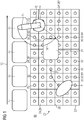
- FIG. 1 shows a robot system 80 with a first robot 10, which has a movable manipulator and is arranged in a working space 20.
- a first transport item 15 and a second item to be transported 17 are guided along a conveying direction 13 to the first robot 10.
- the first robot 10 is designed to grip with the manipulator 12 each a piece of the transported goods 15, 17 and to convey in a pivoting movement to a tray 23.
- the first robot 10 and the tray 23 are mounted in the working space 20.
- the working space 20 is divided into a plurality of substantially rectangular working segments 24 which adjoin one another along parting lines 28.
- the working segments 24 are substantially not shown in detail cuboid space segments, which are bounded on a lower side in each case by the bottom 22 of the working space.
- a floor segment 26 belongs to each workspace segment 24, wherein the floor segments 26 likewise adjoin one another along the imaginary parting lines 28.
- the floor segments 26 are each provided with a lighting element 30, which is designed as a segment light.
- the segment lights 32 are each formed to issue on the surfaces of a ground segment 26 by means of lighting a visual warning.
- FIG. 1 further shows a person P, who moves along a path 27 in the working space 20.
- a robot movement 18 is shown with an arrow to be performed by the first robot 10 in a working interval 50, not shown.
- the arrow direction represents the time sequence of the robot movement 18.
- the first robot 10 passes through a space 19, which has a substantially circular arc shape.
- the traversed space 19 intersects with a plurality of working space segments 24 and passes over their associated floor segments 26.
- a working space segment 24 'with its associated ground segment 26' is shown, which is traversed in the course of the robot movement 18 in front of a second working segment 24 "and its associated ground segment 26" by the first robot.
- the first floor segment 26 ' is in an in FIG. 1 Not shown first period 26 overstretched by the first robot 10, so that a first visual warning 62 on the first floor segment 26 'is output.
- the second floor segment 26 "is only swept over by the first robot 10 in a later, not shown, second time period 54, so that a second visual warning 64 is emitted via a luminous element 30 at the second floor segment 26".
- the different visual warnings 62, 64 and the guard signal 69 indicate to the person P what hazard potential exists in which area of the working space 20.
- a flow chart of the method according to the invention is shown.
- a prediction of a robot movement 18 is carried out by the at least one a first robot 10 is to be performed in a working interval 50.
- its planned motion sequence is predicted under the assumption that no events occur during that lead to a standstill or a deceleration of the at least one first robot 10.
- either the fourth method step 140 or the fifth method step 150 takes place for a workspace segment 24. If it is determined in the preceding determination step 130 that the working space segment 24 at least partially lies in the space 19 passed through by the robot 10 during the first time period 52, a first visual warning 52 is output at the associated floor segment 26. If it is determined in the preceding method step 130 that the working space segment 24 at least partially lies in the traversed space 19 during the second time period 54, a second visual warning 64 is output at the associated floor segment 26.
- FIG. 3 shows the timing of a further embodiment of the method according to the invention.
- Starting point is the start time 51, which is the beginning of the work interval 50 defined.
- a first period 52 emerges, which also essentially begins at start time 51. If during the method steps 110, 120, 130, which are not shown in greater detail, it is determined that a working space segment 24, which is likewise not shown, is passed through within the first time period 52, a first visual warning 62 is output at the associated floor segment 26 within the scope of the fourth method step 140.
- the first period 52 is followed by a second period 54. If a working space segment 24 is traversed during the second period 54, a second visual warning 64 is output in the context of the fifth method step 150.
- the second period 54 is in the range of the work interval 50.
- the second period 54 is followed by a third period 56, which also ends essentially at the end of the work interval 50. If a workspace segment 24 is traversed during the third time period 56, a third visual warning 66 is output at the associated floor segment 26. Further disclosed FIG. 3 an additional period 59, which is after the end of the work interval 50. If a working space segment 24 does not pass through until the beginning of the additional period 59, a guard signal 69 is output in the associated ground segment 26.
- the arrow 57 depicts the timing, so that the working interval 50, as well as the periods 52, 54, 59 are always periods to be understood relative to a start time 51 of a consideration. The periods 52, 54, 56, 59 thus migrate along the arrow 57 during operation of the associated robot system 80. This in FIG. 3 The method illustrated is carried out by continuously repeating the individual method steps 110, 120, 130, 140 and 150.
- FIG. 4 shows a further embodiment of the robot system 80 according to the invention in the working space 20.
- a first transport item 15 and a second item to be transported 17 are guided along a conveying direction 13 to the first robot 10.
- the first robot 10 is designed to grip with the manipulator 12 each a piece of the transported goods 15, 17 and to convey in a pivoting movement to the tray 23.
- the first robot 10 and the tray 23 are mounted in the working space 20.
- the working space 20 is divided into a plurality of substantially rectangular working segments 24 which adjoin one another along parting lines 28.
- the working segments 24 are essentially cuboid space segments which are not shown in more detail and which are delimited on the lower side by the bottom 22 of the working space.
- a floor segment 26 belongs to each workspace segment 24, wherein the floor segments 26 likewise adjoin one another along the imaginary parting lines 28.
- the floor segments 26 are each provided with a lighting element 30, which is designed as a segment light.
- the segment lights 32 are each designed to output a visual warning on the surface of a bottom segment 26 by means of illumination.
- FIG. 4 further shows a second robot 11, which has a manipulator 12 and in the area of the tray 23 performs a step.
- the first and second robots 10, 11 each execute simultaneous movements 18, in each of which a space 19 is traversed.
- Working space segments 24 are at least partially in the traversed space 19, which is assigned to the robots 10, 11.
- the direction of the movements 18 is in FIG. 4 each illustrated with an arrow.
- the direction of the arrow corresponds to the time sequence of the respective movement 18 in the working interval (not shown) 50.
- the working space segment 24 "in the area of the tray 23 is traversed by both robots during the working interval 50.
- the first robot 10 passes through the working space segment 24" at the end of its movement 18 in the second period 54, which is also not shown.
- the robot system 80 recognizes on the basis of the method according to the invention that in the working space segment 24'" already in the first period 52 a hazard potential exists and gives in the associated ground segment 26 '"the first visual warning 62.
- the first visual warning 62 is thereby by means of Luminous element 30 is output, which is designed as a segmental light 32.
- the guard signal 69 is output.
- FIG. 5 schematically shows the structure of the robot system 80 according to the invention, which comprises two robots 10, 11.
- Each of the robots 10, 11 has a manipulator 12, which is driven by an actuator 16.
- the robots 10, 11 are furthermore equipped with a sensor system 14, which, for example, makes it possible to detect the presence of a person and to forward the associated information to the controller of the robots 10, 11.
- the robots 10, 11 are arranged in the working space 20 for performing work steps on the first and second transported goods 15, 17.
- the transported goods 15, 17 each have a texture information 72, which can be detected by the sensors 14 of the robots 10, 11.
- the robots 10, 11 are capable of forwarding the acquired condition information 72 to a control unit 40 via a connection 42.
- connection 42 is suitable for transporting data and is formed between the first robot 10 and the control unit 40 as a data cable 44.
- the second robot 11 is coupled via a connection 42 to the control unit 40, which is designed as a radio link.
- FIG. 5 schematically a plurality of floor segments 26, each one a work space segment, not shown 24 are assigned.
- the floor segments 26 are provided with segment lights 32, which serve as lighting means 30.
- a single segmental luminaire 32 is adapted to cause on at least one ground segment 26 a visual warning 62, 64, 66 or a draft signal 69.
- a ground segment 26 is coupled to the control unit 40 via radio link 46.
- the further ground segments 36 are connected to the control unit 40 via data cables 44, which serve as connection 42.
- the control unit 40 is further coupled via the data cable 44 with a controllable image projector 34, which is designed as a beamer, which is able to output on the ground segments 26 and a visual warning 62, 64, 66.
- controllable image projector 34 is suitable for producing a visual warning 62, 64, 66 or a warning signal 69 on ground segments 26 (not shown) without a lighting means 30.
- the controllable image projector 34 can be controlled via the control unit 40 in such a way that a constant or temporally variable light pattern is output as a visual warning 62, 64, 66 or as a guard signal 69.
- the visual warning 62, 64, 66 is capable of accepting different colors, may include color transitions, or be configured as stationary or animated symbols.
- the robotic system 80 is also provided with an acoustic warning buzzer 36 which is connected to the control unit 40 via the data cable 44 and is adapted to additionally output an audible warning to a person in the work space 20 in situations of increased hazard potential.
- the control unit 40 has a memory on which a computer program 90 is stored executable, which implements the inventive method in the robot system 80.
- the computer program 90 is designed such that it processes and evaluates all information acquired via robots 10, 11 and sent via the connections 42 via data cable 44 or radio link 46, such as process parameters 70.
- the computer program 90 is also suitable for supplying control signals to the individual lighting means 30, the controllable image projector 34 or the acoustic To send warning buzzer 36 which cause the corresponding visual warnings 62, 64, 66, audible warnings 68 and the Entwarnsignal 69.
Landscapes
- Engineering & Computer Science (AREA)
- Physics & Mathematics (AREA)
- General Physics & Mathematics (AREA)
- Robotics (AREA)
- Mechanical Engineering (AREA)
- Business, Economics & Management (AREA)
- Emergency Management (AREA)
- Computing Systems (AREA)
- Multimedia (AREA)
- Manipulator (AREA)
- Emergency Alarm Devices (AREA)
Claims (15)
- Procédé pour prévenir une personne de la présence d'au moins un premier robot (10) dans un espace (20) de travail, qui comprend une multiplicité de segments (26) de plancher, respectivement un segment (24) d'espace de travail étant affecté aux segments (26) de plancher, comprenant les stades :a) on pronostique un déplacement (18) du robot, qui s'effectue par au moins un premier robot (10) dans un intervalle (50) de travail, l'intervalle (50) de travail comprenant un premier laps de temps (52) et un deuxième laps de temps (54) ultérieur;b) on détermine un espace (19) dans lequel, pendant l'intervalle (50) de travail, au moins un premier robot (10) est passé;c) on détermine au moins un segment (24) d'espace de travail, qui, dans le premier ou le deuxième laps de temps (52, 54), se trouve au moins en partie dans l'espace (19) parcouru;
, si on est passé dans le segment (24) d'espace de travail associé dans le premier laps de temps (52);d) on émet un premier avertissement (62) visuel vers un segment (26) de plancher, si on est passé dans le segment (24) d'espace de travail associé dans le premier laps de temps (52), si le segment (24) d'espace de travail associé a été parcouru dans le premier laps de temps (52) ete) on émet un deuxième avertissement (64) visuel vers un segment (26) de plancher, si le segment (24) d'espace de travail associé a été parcouru dans le deuxième laps de temps (52). - Procédé suivant la revendication 1, caractérisé en ce que, dans le stade b), on détecte si ensemble au moins un premier robot (18) et une première marchandise (15) à transporter sont passés dans l'espace (19).
- Procédé suivant la revendication 1 ou 2, caractérisé en ce que le premier et le deuxième avertissements (62, 64) visuels sont constitués chacun sous la forme d'un signal coloré ou d'un motif lumineux.
- Procédé suivant l'une des revendications 1 à 3, caractérisé en ce que l'on effectue le stade c) également pendant un au moins un troisième laps de temps (56) et, dans au moins un autre stade f), on émet un troisième avertissement (66) visuel vers un segment (26) de plancher, si le segment (24) d'espace de travail associé a été parcouru.
- Procédé suivant l'une des revendications 1 à 4, caractérisé en ce que, dans l'un des stades d) à f) du procédé, on émet (68), en outre, un avertissement (68) acoustique.
- Procédé suivant l'une des revendications 1 à 5, caractérisé en ce que les avertissements (62, 64, 66) visuels et/ou l'avertissement (68) acoustique sont formés en fonction d'au moins un paramètre (70) opératoire du au moins un premier robot (10).
- Procédé suivant la revendication 5, caractérisé en ce que le a moins un paramètre (70) opératoire comprend une vitesse de déplacement du au moins un premier robot (10) et/ou une information (72) de l'état de la première ou d'une deuxième marchandise (15, 17) à transporter.
- Procédé suivant l'une des revendications 1 à 7, caractérisé en ce que, dans un autre stade g), on émet, dans respectivement un segment (26) de plancher, un signal (69) visuel de fin d'avertissement si le au moins un premier robot (10) n'est pas passé dans le segment (24) d'espace de travail associé pendant l'intervalle (50) de temps.
- Procédé suivant l'une des revendications 1 à 8, caractérisé en ce que l'on effectue les stades a) à c) du procédé supplémentairement pour au moins un deuxième robot (11).
- Système (80) de robot, comprenant une unité (40) de commande, au moins un premier robot (10), qui est relié à l'unité (40) de commande et qui est disposé dans un espace (20) de travail, l'espace (20) de travail comprenant une multiplicité de segments (24) d'espace de travail auxquels sont associés respectivement des segments (26) de plancher, au moins un élément (30) lumineux, qui est relié à l'unité (40) de commande et qui est constitué pour émettre, vers au moins un segment (26) de plancher, respectivement un avertissement (62, 64, 66) visuel, caractérisé en ce que l'unité (40) de commande est constituée pour effectuer un procédé suivant l'une des revendications 1 à 9.
- Système (80) de robot suivant la revendication 10, caractérisé en ce que le système (80) de robot comprend au moins un deuxième robot (11).
- Système (80) de robot suivant l'une des revendications 10 ou 11, caractérisé en ce que le au moins un élément (30) lumineux est constitué sous la forme d'une pluralité d'éclairages (32) segmentés, qui sont mis respectivement sur ou au dessus du segment (26) de plancher associé.
- Système (80) de robot suivant l'une des revendications 11 ou 12, caractérisé en ce que le au moins un élément (30) lumineux est constitué sous la forme d'un projecteur (34) d'images, qui peut être commandé et qui est mis au dessus des segments (26) de plancher associés.
- Programme (90) informatique mémorisé sur une mémoire ou sur un support de données et propre à effectuer un procédé suivant l'une des revendications 1 à 9 sur un système (80) de robot suivant l'une des revendications 10 à 13.
- Unité (40) de commande, comprenant une mémoire, caractérisée en ce qu'un programme (90) informatique, suivant la revendication 14, est mémorisé sur la mémoire, de manière à pouvoir être exécuté.
Applications Claiming Priority (1)
| Application Number | Priority Date | Filing Date | Title |
|---|---|---|---|
| PCT/EP2014/064079 WO2016000770A1 (fr) | 2014-07-02 | 2014-07-02 | Procédé d'alerte et système robotisé |
Publications (2)
| Publication Number | Publication Date |
|---|---|
| EP3140087A1 EP3140087A1 (fr) | 2017-03-15 |
| EP3140087B1 true EP3140087B1 (fr) | 2018-06-27 |
Family
ID=51063431
Family Applications (1)
| Application Number | Title | Priority Date | Filing Date |
|---|---|---|---|
| EP14735560.6A Active EP3140087B1 (fr) | 2014-07-02 | 2014-07-02 | Procédé d'alerte et système robotisé |
Country Status (5)
| Country | Link |
|---|---|
| US (1) | US9908244B2 (fr) |
| EP (1) | EP3140087B1 (fr) |
| JP (1) | JP6462012B2 (fr) |
| CN (1) | CN106660215B (fr) |
| WO (1) | WO2016000770A1 (fr) |
Families Citing this family (12)
| Publication number | Priority date | Publication date | Assignee | Title |
|---|---|---|---|---|
| WO2016173609A1 (fr) * | 2015-04-27 | 2016-11-03 | Abb Technology Ltd | Indicateur de mouvement pour un robot |
| DE102015215234A1 (de) * | 2015-08-10 | 2017-02-16 | Fraunhofer-Gesellschaft zur Förderung der angewandten Forschung e.V. | Einrichtung zum Absichern eines Sicherheitsbereichs um mindestens eine automatisch arbeitende Maschine |
| JP2017148905A (ja) * | 2016-02-25 | 2017-08-31 | ファナック株式会社 | ロボットシステムおよびロボット制御装置 |
| WO2017218586A1 (fr) * | 2016-06-13 | 2017-12-21 | Gamma2Robotics | Procédés et systèmes pour réduire les fausses alarmes dans un dispositif robotique par fusion de capteurs |
| CN106406312B (zh) * | 2016-10-14 | 2017-12-26 | 平安科技(深圳)有限公司 | 导览机器人及其移动区域标定方法 |
| EP3422053B1 (fr) * | 2017-06-28 | 2021-05-19 | Datalogic IP Tech S.r.l. | Système de sécurité |
| DE102017009641A1 (de) * | 2017-10-17 | 2019-04-18 | Kuka Deutschland Gmbh | Verfahren und System zum Betreiben eines Roboterarms |
| KR102499576B1 (ko) | 2018-01-08 | 2023-02-15 | 삼성전자주식회사 | 전자 장치 및 그 제어 방법 |
| DE102018114156B3 (de) * | 2018-06-13 | 2019-11-14 | Volkswagen Aktiengesellschaft | Verfahren zur Steuerung eines Roboters, insbesondere eines Industrieroboters, sowie Vorrichtung zur Steuerung des Roboters |
| DE102018220561A1 (de) * | 2018-11-29 | 2020-06-04 | Robert Bosch Gmbh | Doppelbodenelement für einen Doppelboden |
| JP6647640B1 (ja) * | 2019-04-15 | 2020-02-14 | 日本金銭機械株式会社 | 表示制御システム、表示制御方法、および、プログラム |
| DE102019123581A1 (de) * | 2019-09-03 | 2021-03-04 | Pilz Gmbh & Co. Kg | Vorrichtung und Verfahren zur Ausführung einer Sicherheitsfunktion |
Family Cites Families (28)
| Publication number | Priority date | Publication date | Assignee | Title |
|---|---|---|---|---|
| EP0158593B1 (fr) * | 1984-04-09 | 1989-05-24 | GET Gesellschaft für Elektronik-Technologie mbH | Dispositif électronique de surveillance et d'avertissement pour manipulateur |
| JPS6442797A (en) * | 1987-08-11 | 1989-02-15 | Fuji Electric Co Ltd | Display successively changing color |
| JPH05229784A (ja) | 1992-02-21 | 1993-09-07 | Shimizu Corp | クレーン下方の安全監視システム |
| JP2004027528A (ja) * | 2002-06-21 | 2004-01-29 | Matsushita Electric Works Ltd | 道路情報表示システム |
| EP1535706A1 (fr) * | 2002-07-18 | 2005-06-01 | Kabushiki Kaisha Yaskawa Denki | Commande de robot et systeme robot |
| JP4304133B2 (ja) * | 2004-07-30 | 2009-07-29 | 東芝機械株式会社 | 産業用ロボットの移動時間表示装置 |
| JP2006285635A (ja) * | 2005-03-31 | 2006-10-19 | Toshiba Corp | 表示案内装置、ロボットシステム及びロボットシステムにおける表示案内方法 |
| JP4764070B2 (ja) * | 2005-05-24 | 2011-08-31 | 本田技研工業株式会社 | 作業ステーションの安全システム |
| JP4560547B2 (ja) * | 2005-07-19 | 2010-10-13 | オムロン株式会社 | 作業者安全管理システム |
| CN101432103B (zh) * | 2006-07-04 | 2012-05-23 | 松下电器产业株式会社 | 机器人手臂的控制装置 |
| EP1901150B1 (fr) * | 2006-09-14 | 2008-10-29 | Abb Research Ltd. | Procédé et dispositif permettant d'éviter les collisions entre un robot industriel et un objet |
| JP2009123045A (ja) * | 2007-11-16 | 2009-06-04 | Toyota Motor Corp | 移動ロボット及び移動ロボットの危険範囲の表示方法 |
| JP5343641B2 (ja) * | 2009-03-12 | 2013-11-13 | 株式会社Ihi | ロボット装置の制御装置及びロボット装置の制御方法 |
| FR2946022B1 (fr) * | 2009-05-26 | 2013-02-08 | Airbus France | Systeme de protection de zones dangereuses. |
| FR2948339A1 (fr) * | 2009-07-22 | 2011-01-28 | Sidel Participations | Perfectionnement a une installation de palettisation combinee avec acces securise. |
| US8253792B2 (en) * | 2009-08-28 | 2012-08-28 | GM Global Technology Operations LLC | Vision system for monitoring humans in dynamic environments |
| CN102448681B (zh) * | 2009-12-28 | 2014-09-10 | 松下电器产业株式会社 | 动作空间提示装置、动作空间提示方法以及程序 |
| JP5059978B2 (ja) * | 2010-01-25 | 2012-10-31 | パナソニック株式会社 | 危険提示装置、危険提示システム、危険提示方法およびプログラム |
| US9596451B2 (en) * | 2010-04-16 | 2017-03-14 | Fraunhofer Gesellschaft Zur Föderung Der Angewandten Forschung E.V. | Device for monitoring at least one three-dimensional safety area |
| DE102010032917A1 (de) * | 2010-07-30 | 2012-04-19 | Brötje-Automation GmbH | Verfahren zur Offline-Programmierung eines NC-gesteuerten Manipulators |
| JP5454491B2 (ja) * | 2011-02-25 | 2014-03-26 | 株式会社安川電機 | 作業システム |
| JP2012236244A (ja) * | 2011-05-10 | 2012-12-06 | Sony Corp | ロボット装置、ロボット装置の制御方法、並びにロボット装置制御用プログラム |
| JP5924134B2 (ja) * | 2012-05-30 | 2016-05-25 | セイコーエプソン株式会社 | 侵入検出装置,ロボットシステム,侵入検出方法および侵入検出プログラム |
| CN104870147B (zh) * | 2012-08-31 | 2016-09-14 | 睿信科机器人有限公司 | 机器人安全工作的系统和方法 |
| US9643318B2 (en) * | 2012-12-03 | 2017-05-09 | Abb Schweiz Ag | Teleoperation of machines having at least one actuated mechanism |
| US20150294496A1 (en) * | 2014-04-14 | 2015-10-15 | GM Global Technology Operations LLC | Probabilistic person-tracking using multi-view fusion |
| US9415513B2 (en) * | 2014-08-29 | 2016-08-16 | General Electric Company | Systems and methods for railyard robotics |
| EP3017920B1 (fr) * | 2014-11-07 | 2017-08-23 | Comau S.p.A. | Robot industriel et procédé pour commander un tel robot |
-
2014
- 2014-07-02 CN CN201480080286.7A patent/CN106660215B/zh active Active
- 2014-07-02 EP EP14735560.6A patent/EP3140087B1/fr active Active
- 2014-07-02 US US15/322,364 patent/US9908244B2/en active Active
- 2014-07-02 JP JP2016575329A patent/JP6462012B2/ja active Active
- 2014-07-02 WO PCT/EP2014/064079 patent/WO2016000770A1/fr active Application Filing
Non-Patent Citations (1)
| Title |
|---|
| None * |
Also Published As
| Publication number | Publication date |
|---|---|
| EP3140087A1 (fr) | 2017-03-15 |
| US9908244B2 (en) | 2018-03-06 |
| JP2017520419A (ja) | 2017-07-27 |
| CN106660215A (zh) | 2017-05-10 |
| CN106660215B (zh) | 2021-09-17 |
| JP6462012B2 (ja) | 2019-01-30 |
| US20170120460A1 (en) | 2017-05-04 |
| WO2016000770A1 (fr) | 2016-01-07 |
Similar Documents
| Publication | Publication Date | Title |
|---|---|---|
| EP3140087B1 (fr) | Procédé d'alerte et système robotisé | |
| EP3383595B1 (fr) | Représentation de zones protégées variables | |
| DE102009009472B4 (de) | Verfahren zum Unterstützen eines Fahrers eines Fahrzeugs und Fahrerassistenzsystem für ein Fahrzeug | |
| EP2837473A2 (fr) | Unité de projection pour une plate-forme mobile automatique, robot de transport et procédé de fonctionnement d'une plate-forme mobile automatique | |
| EP2464992B1 (fr) | Collision surpervision pour véhicule | |
| DE102018009028A1 (de) | Unterstützungssystem für einen Notfall-Spurwechsel | |
| DE102016113913A1 (de) | Kommunikationsvorrichtung für ein Fahrzeug, insbesondere für ein autonomes oder teilautonomes Fahrzeug | |
| DE112014006874T5 (de) | Straßenfläche-Beleuchtungseinrichtung | |
| DE202014010054U1 (de) | Protektofon - eine kognitive Sicherheitsfunktion | |
| EP3663252B1 (fr) | Procédé pour faire fonctionner un agv et système intralogistique avec un agv | |
| DE102016113312A1 (de) | Fahrzeugsicherheitsvorrichtung mit Warnzonen | |
| DE102014016815A1 (de) | Verfahren zum Betrieb eines Fahrzeuges | |
| DE102006035929A1 (de) | Verfahren zum sensorgestützten Unterfahren eines Objekts bzw. zum Einfahren in ein Objekt mit einem Nutzfahrzeug | |
| EP3818466B1 (fr) | Reconnaissance rapide d'objets dangereux ou menacés dans l'environnement d'un véhicule | |
| WO2018041613A1 (fr) | Surveillance de systèmes de transport ferroviaires | |
| WO2017134108A1 (fr) | Véhicule automobile | |
| DE102019131774A1 (de) | Überwachungssystem für Roboter und Robotersystem | |
| EP3396360A1 (fr) | Installation de vérification optique des zones de surfaces des objets | |
| DE102016001201B4 (de) | Kraftfahrzeug | |
| DE202018102420U1 (de) | Fahrzeugseitenbeleuchtungsanordnung | |
| WO2004025385A1 (fr) | Procede et dispositif pour faire fonctionner un dispositif indicateur sur une machine-outil | |
| DE102015001575A1 (de) | Verfahren und Vorrichtung zur Visualisierung der Bewegung eines Roboters | |
| EP3691937B1 (fr) | Système de nettoyage de véhicules avec installation de signalisation et méthode de détermination et représentation d'informations d'entrée de véhicules | |
| DE102016215484A1 (de) | Verfahren und Vorrichtung zum Signalisieren eines fahrerlosen Betriebszustands eines Kraftfahrzeugs | |
| EP3687859B1 (fr) | Procédé destiné à éclairer une zone de chaussée en projetant une trajectoire et véhicule automobile |
Legal Events
| Date | Code | Title | Description |
|---|---|---|---|
| PUAI | Public reference made under article 153(3) epc to a published international application that has entered the european phase |
Free format text: ORIGINAL CODE: 0009012 |
|
| 17P | Request for examination filed |
Effective date: 20161206 |
|
| AK | Designated contracting states |
Kind code of ref document: A1 Designated state(s): AL AT BE BG CH CY CZ DE DK EE ES FI FR GB GR HR HU IE IS IT LI LT LU LV MC MK MT NL NO PL PT RO RS SE SI SK SM TR |
|
| AX | Request for extension of the european patent |
Extension state: BA ME |
|
| RAP1 | Party data changed (applicant data changed or rights of an application transferred) |
Owner name: SIEMENS AKTIENGESELLSCHAFT |
|
| DAX | Request for extension of the european patent (deleted) | ||
| REG | Reference to a national code |
Ref country code: DE Ref legal event code: R079 Ref document number: 502014008667 Country of ref document: DE Free format text: PREVIOUS MAIN CLASS: B25J0019060000 Ipc: G08B0021020000 |
|
| GRAP | Despatch of communication of intention to grant a patent |
Free format text: ORIGINAL CODE: EPIDOSNIGR1 |
|
| RIC1 | Information provided on ipc code assigned before grant |
Ipc: B25J 19/06 20060101ALI20180110BHEP Ipc: G08B 21/02 20060101AFI20180110BHEP Ipc: G08B 31/00 20060101ALI20180110BHEP Ipc: B25J 9/16 20060101ALI20180110BHEP |
|
| INTG | Intention to grant announced |
Effective date: 20180206 |
|
| GRAS | Grant fee paid |
Free format text: ORIGINAL CODE: EPIDOSNIGR3 |
|
| GRAA | (expected) grant |
Free format text: ORIGINAL CODE: 0009210 |
|
| AK | Designated contracting states |
Kind code of ref document: B1 Designated state(s): AL AT BE BG CH CY CZ DE DK EE ES FI FR GB GR HR HU IE IS IT LI LT LU LV MC MK MT NL NO PL PT RO RS SE SI SK SM TR |
|
| REG | Reference to a national code |
Ref country code: GB Ref legal event code: FG4D Free format text: NOT ENGLISH |
|
| REG | Reference to a national code |
Ref country code: AT Ref legal event code: REF Ref document number: 1012986 Country of ref document: AT Kind code of ref document: T Effective date: 20180715 |
|
| REG | Reference to a national code |
Ref country code: IE Ref legal event code: FG4D Free format text: LANGUAGE OF EP DOCUMENT: GERMAN |
|
| REG | Reference to a national code |
Ref country code: DE Ref legal event code: R096 Ref document number: 502014008667 Country of ref document: DE Ref country code: FR Ref legal event code: PLFP Year of fee payment: 5 |
|
| REG | Reference to a national code |
Ref country code: CH Ref legal event code: NV Representative=s name: SIEMENS SCHWEIZ AG, CH |
|
| PG25 | Lapsed in a contracting state [announced via postgrant information from national office to epo] |
Ref country code: BG Free format text: LAPSE BECAUSE OF FAILURE TO SUBMIT A TRANSLATION OF THE DESCRIPTION OR TO PAY THE FEE WITHIN THE PRESCRIBED TIME-LIMIT Effective date: 20180927 Ref country code: LT Free format text: LAPSE BECAUSE OF FAILURE TO SUBMIT A TRANSLATION OF THE DESCRIPTION OR TO PAY THE FEE WITHIN THE PRESCRIBED TIME-LIMIT Effective date: 20180627 Ref country code: FI Free format text: LAPSE BECAUSE OF FAILURE TO SUBMIT A TRANSLATION OF THE DESCRIPTION OR TO PAY THE FEE WITHIN THE PRESCRIBED TIME-LIMIT Effective date: 20180627 Ref country code: NO Free format text: LAPSE BECAUSE OF FAILURE TO SUBMIT A TRANSLATION OF THE DESCRIPTION OR TO PAY THE FEE WITHIN THE PRESCRIBED TIME-LIMIT Effective date: 20180927 Ref country code: SE Free format text: LAPSE BECAUSE OF FAILURE TO SUBMIT A TRANSLATION OF THE DESCRIPTION OR TO PAY THE FEE WITHIN THE PRESCRIBED TIME-LIMIT Effective date: 20180627 |
|
| REG | Reference to a national code |
Ref country code: NL Ref legal event code: MP Effective date: 20180627 |
|
| REG | Reference to a national code |
Ref country code: LT Ref legal event code: MG4D |
|
| PG25 | Lapsed in a contracting state [announced via postgrant information from national office to epo] |
Ref country code: RS Free format text: LAPSE BECAUSE OF FAILURE TO SUBMIT A TRANSLATION OF THE DESCRIPTION OR TO PAY THE FEE WITHIN THE PRESCRIBED TIME-LIMIT Effective date: 20180627 Ref country code: GR Free format text: LAPSE BECAUSE OF FAILURE TO SUBMIT A TRANSLATION OF THE DESCRIPTION OR TO PAY THE FEE WITHIN THE PRESCRIBED TIME-LIMIT Effective date: 20180928 Ref country code: HR Free format text: LAPSE BECAUSE OF FAILURE TO SUBMIT A TRANSLATION OF THE DESCRIPTION OR TO PAY THE FEE WITHIN THE PRESCRIBED TIME-LIMIT Effective date: 20180627 Ref country code: LV Free format text: LAPSE BECAUSE OF FAILURE TO SUBMIT A TRANSLATION OF THE DESCRIPTION OR TO PAY THE FEE WITHIN THE PRESCRIBED TIME-LIMIT Effective date: 20180627 |
|
| PG25 | Lapsed in a contracting state [announced via postgrant information from national office to epo] |
Ref country code: NL Free format text: LAPSE BECAUSE OF FAILURE TO SUBMIT A TRANSLATION OF THE DESCRIPTION OR TO PAY THE FEE WITHIN THE PRESCRIBED TIME-LIMIT Effective date: 20180627 |
|
| PG25 | Lapsed in a contracting state [announced via postgrant information from national office to epo] |
Ref country code: SK Free format text: LAPSE BECAUSE OF FAILURE TO SUBMIT A TRANSLATION OF THE DESCRIPTION OR TO PAY THE FEE WITHIN THE PRESCRIBED TIME-LIMIT Effective date: 20180627 Ref country code: RO Free format text: LAPSE BECAUSE OF FAILURE TO SUBMIT A TRANSLATION OF THE DESCRIPTION OR TO PAY THE FEE WITHIN THE PRESCRIBED TIME-LIMIT Effective date: 20180627 Ref country code: CZ Free format text: LAPSE BECAUSE OF FAILURE TO SUBMIT A TRANSLATION OF THE DESCRIPTION OR TO PAY THE FEE WITHIN THE PRESCRIBED TIME-LIMIT Effective date: 20180627 Ref country code: PL Free format text: LAPSE BECAUSE OF FAILURE TO SUBMIT A TRANSLATION OF THE DESCRIPTION OR TO PAY THE FEE WITHIN THE PRESCRIBED TIME-LIMIT Effective date: 20180627 Ref country code: EE Free format text: LAPSE BECAUSE OF FAILURE TO SUBMIT A TRANSLATION OF THE DESCRIPTION OR TO PAY THE FEE WITHIN THE PRESCRIBED TIME-LIMIT Effective date: 20180627 Ref country code: IS Free format text: LAPSE BECAUSE OF FAILURE TO SUBMIT A TRANSLATION OF THE DESCRIPTION OR TO PAY THE FEE WITHIN THE PRESCRIBED TIME-LIMIT Effective date: 20181027 |
|
| PG25 | Lapsed in a contracting state [announced via postgrant information from national office to epo] |
Ref country code: SM Free format text: LAPSE BECAUSE OF FAILURE TO SUBMIT A TRANSLATION OF THE DESCRIPTION OR TO PAY THE FEE WITHIN THE PRESCRIBED TIME-LIMIT Effective date: 20180627 Ref country code: ES Free format text: LAPSE BECAUSE OF FAILURE TO SUBMIT A TRANSLATION OF THE DESCRIPTION OR TO PAY THE FEE WITHIN THE PRESCRIBED TIME-LIMIT Effective date: 20180627 |
|
| REG | Reference to a national code |
Ref country code: DE Ref legal event code: R097 Ref document number: 502014008667 Country of ref document: DE |
|
| PG25 | Lapsed in a contracting state [announced via postgrant information from national office to epo] |
Ref country code: LU Free format text: LAPSE BECAUSE OF NON-PAYMENT OF DUE FEES Effective date: 20180702 Ref country code: MC Free format text: LAPSE BECAUSE OF FAILURE TO SUBMIT A TRANSLATION OF THE DESCRIPTION OR TO PAY THE FEE WITHIN THE PRESCRIBED TIME-LIMIT Effective date: 20180627 |
|
| REG | Reference to a national code |
Ref country code: BE Ref legal event code: MM Effective date: 20180731 |
|
| REG | Reference to a national code |
Ref country code: IE Ref legal event code: MM4A |
|
| PG25 | Lapsed in a contracting state [announced via postgrant information from national office to epo] |
Ref country code: IE Free format text: LAPSE BECAUSE OF NON-PAYMENT OF DUE FEES Effective date: 20180702 |
|
| PLBE | No opposition filed within time limit |
Free format text: ORIGINAL CODE: 0009261 |
|
| STAA | Information on the status of an ep patent application or granted ep patent |
Free format text: STATUS: NO OPPOSITION FILED WITHIN TIME LIMIT |
|
| GBPC | Gb: european patent ceased through non-payment of renewal fee |
Effective date: 20180927 |
|
| PG25 | Lapsed in a contracting state [announced via postgrant information from national office to epo] |
Ref country code: DK Free format text: LAPSE BECAUSE OF FAILURE TO SUBMIT A TRANSLATION OF THE DESCRIPTION OR TO PAY THE FEE WITHIN THE PRESCRIBED TIME-LIMIT Effective date: 20180627 Ref country code: BE Free format text: LAPSE BECAUSE OF NON-PAYMENT OF DUE FEES Effective date: 20180731 |
|
| 26N | No opposition filed |
Effective date: 20190328 |
|
| PG25 | Lapsed in a contracting state [announced via postgrant information from national office to epo] |
Ref country code: SI Free format text: LAPSE BECAUSE OF FAILURE TO SUBMIT A TRANSLATION OF THE DESCRIPTION OR TO PAY THE FEE WITHIN THE PRESCRIBED TIME-LIMIT Effective date: 20180627 |
|
| PG25 | Lapsed in a contracting state [announced via postgrant information from national office to epo] |
Ref country code: GB Free format text: LAPSE BECAUSE OF NON-PAYMENT OF DUE FEES Effective date: 20180927 |
|
| PG25 | Lapsed in a contracting state [announced via postgrant information from national office to epo] |
Ref country code: AL Free format text: LAPSE BECAUSE OF FAILURE TO SUBMIT A TRANSLATION OF THE DESCRIPTION OR TO PAY THE FEE WITHIN THE PRESCRIBED TIME-LIMIT Effective date: 20180627 |
|
| PG25 | Lapsed in a contracting state [announced via postgrant information from national office to epo] |
Ref country code: MT Free format text: LAPSE BECAUSE OF FAILURE TO SUBMIT A TRANSLATION OF THE DESCRIPTION OR TO PAY THE FEE WITHIN THE PRESCRIBED TIME-LIMIT Effective date: 20180627 |
|
| PG25 | Lapsed in a contracting state [announced via postgrant information from national office to epo] |
Ref country code: TR Free format text: LAPSE BECAUSE OF FAILURE TO SUBMIT A TRANSLATION OF THE DESCRIPTION OR TO PAY THE FEE WITHIN THE PRESCRIBED TIME-LIMIT Effective date: 20180627 |
|
| PG25 | Lapsed in a contracting state [announced via postgrant information from national office to epo] |
Ref country code: PT Free format text: LAPSE BECAUSE OF FAILURE TO SUBMIT A TRANSLATION OF THE DESCRIPTION OR TO PAY THE FEE WITHIN THE PRESCRIBED TIME-LIMIT Effective date: 20180627 |
|
| PG25 | Lapsed in a contracting state [announced via postgrant information from national office to epo] |
Ref country code: MK Free format text: LAPSE BECAUSE OF NON-PAYMENT OF DUE FEES Effective date: 20180627 Ref country code: HU Free format text: LAPSE BECAUSE OF FAILURE TO SUBMIT A TRANSLATION OF THE DESCRIPTION OR TO PAY THE FEE WITHIN THE PRESCRIBED TIME-LIMIT; INVALID AB INITIO Effective date: 20140702 Ref country code: CY Free format text: LAPSE BECAUSE OF FAILURE TO SUBMIT A TRANSLATION OF THE DESCRIPTION OR TO PAY THE FEE WITHIN THE PRESCRIBED TIME-LIMIT Effective date: 20180627 |
|
| PGFP | Annual fee paid to national office [announced via postgrant information from national office to epo] |
Ref country code: IT Payment date: 20230725 Year of fee payment: 10 Ref country code: AT Payment date: 20230609 Year of fee payment: 10 |
|
| PGFP | Annual fee paid to national office [announced via postgrant information from national office to epo] |
Ref country code: FR Payment date: 20230720 Year of fee payment: 10 Ref country code: DE Payment date: 20230918 Year of fee payment: 10 |
|
| PGFP | Annual fee paid to national office [announced via postgrant information from national office to epo] |
Ref country code: CH Payment date: 20231024 Year of fee payment: 10 |