EP3383136A2 - Induktionskochfeldvorrichtung - Google Patents
Induktionskochfeldvorrichtung Download PDFInfo
- Publication number
- EP3383136A2 EP3383136A2 EP18161015.5A EP18161015A EP3383136A2 EP 3383136 A2 EP3383136 A2 EP 3383136A2 EP 18161015 A EP18161015 A EP 18161015A EP 3383136 A2 EP3383136 A2 EP 3383136A2
- Authority
- EP
- European Patent Office
- Prior art keywords
- induction heating
- magnetic flux
- heating elements
- induction
- flux bundling
- Prior art date
- Legal status (The legal status is an assumption and is not a legal conclusion. Google has not performed a legal analysis and makes no representation as to the accuracy of the status listed.)
- Granted
Links
Images


Classifications
-
- H—ELECTRICITY
- H05—ELECTRIC TECHNIQUES NOT OTHERWISE PROVIDED FOR
- H05B—ELECTRIC HEATING; ELECTRIC LIGHT SOURCES NOT OTHERWISE PROVIDED FOR; CIRCUIT ARRANGEMENTS FOR ELECTRIC LIGHT SOURCES, IN GENERAL
- H05B6/00—Heating by electric, magnetic or electromagnetic fields
- H05B6/02—Induction heating
- H05B6/10—Induction heating apparatus, other than furnaces, for specific applications
- H05B6/12—Cooking devices
- H05B6/1209—Cooking devices induction cooking plates or the like and devices to be used in combination with them
- H05B6/1245—Cooking devices induction cooking plates or the like and devices to be used in combination with them with special coil arrangements
- H05B6/1254—Cooking devices induction cooking plates or the like and devices to be used in combination with them with special coil arrangements using conductive pieces to direct the induced magnetic field
-
- H—ELECTRICITY
- H02—GENERATION; CONVERSION OR DISTRIBUTION OF ELECTRIC POWER
- H02J—CIRCUIT ARRANGEMENTS OR SYSTEMS FOR SUPPLYING OR DISTRIBUTING ELECTRIC POWER; SYSTEMS FOR STORING ELECTRIC ENERGY
- H02J50/00—Circuit arrangements or systems for wireless supply or distribution of electric power
- H02J50/10—Circuit arrangements or systems for wireless supply or distribution of electric power using inductive coupling
-
- H—ELECTRICITY
- H05—ELECTRIC TECHNIQUES NOT OTHERWISE PROVIDED FOR
- H05B—ELECTRIC HEATING; ELECTRIC LIGHT SOURCES NOT OTHERWISE PROVIDED FOR; CIRCUIT ARRANGEMENTS FOR ELECTRIC LIGHT SOURCES, IN GENERAL
- H05B6/00—Heating by electric, magnetic or electromagnetic fields
- H05B6/02—Induction heating
- H05B6/10—Induction heating apparatus, other than furnaces, for specific applications
- H05B6/12—Cooking devices
- H05B6/1209—Cooking devices induction cooking plates or the like and devices to be used in combination with them
- H05B6/1245—Cooking devices induction cooking plates or the like and devices to be used in combination with them with special coil arrangements
- H05B6/1272—Cooking devices induction cooking plates or the like and devices to be used in combination with them with special coil arrangements with more than one coil or coil segment per heating zone
-
- H—ELECTRICITY
- H05—ELECTRIC TECHNIQUES NOT OTHERWISE PROVIDED FOR
- H05B—ELECTRIC HEATING; ELECTRIC LIGHT SOURCES NOT OTHERWISE PROVIDED FOR; CIRCUIT ARRANGEMENTS FOR ELECTRIC LIGHT SOURCES, IN GENERAL
- H05B2213/00—Aspects relating both to resistive heating and to induction heating, covered by H05B3/00 and H05B6/00
- H05B2213/03—Heating plates made out of a matrix of heating elements that can define heating areas adapted to cookware randomly placed on the heating plate
-
- Y—GENERAL TAGGING OF NEW TECHNOLOGICAL DEVELOPMENTS; GENERAL TAGGING OF CROSS-SECTIONAL TECHNOLOGIES SPANNING OVER SEVERAL SECTIONS OF THE IPC; TECHNICAL SUBJECTS COVERED BY FORMER USPC CROSS-REFERENCE ART COLLECTIONS [XRACs] AND DIGESTS
- Y02—TECHNOLOGIES OR APPLICATIONS FOR MITIGATION OR ADAPTATION AGAINST CLIMATE CHANGE
- Y02B—CLIMATE CHANGE MITIGATION TECHNOLOGIES RELATED TO BUILDINGS, e.g. HOUSING, HOUSE APPLIANCES OR RELATED END-USER APPLICATIONS
- Y02B40/00—Technologies aiming at improving the efficiency of home appliances, e.g. induction cooking or efficient technologies for refrigerators, freezers or dish washers
Definitions
- the invention relates to an induction hob apparatus according to the preamble of claim 1 and a method for operating an induction hob apparatus according to the preamble of claim 11.
- the invention is based on an induction hob device with at least two overlapping induction heating elements.
- the induction hob apparatus comprise at least one magnetic flux bundling unit which provides for bundling at least one magnetic flux provided by at least one of the induction heating elements is and which has at least one Magnethnendelungselement, which is assigned to the flux bundling the overlapping induction heating.
- a generic device can be further developed advantageous. Due to the magnetic flux-bundling element associated with the overlapping induction heating elements, in particular a small number of magnetic flux-bundling elements can be made possible, whereby in particular low costs and / or a low total weight and / or a small space requirement, especially a low height, can be achieved. In particular, optimum heating of a cooking appliance that is set up in particular can be made possible, in particular due to optimum flux bundling effected by the magnetic flux bundling unit of the magnetic flux provided by at least one of the induction heating elements.
- an "induction hob device” is to be understood in particular as meaning at least one part, in particular a subassembly, of an induction hob.
- the induction heating element is in particular intended to generate an electromagnetic alternating field, in particular with a frequency in a range from 20 kHz to 100 kHz, which is provided in particular in an erected, in particular metallic, preferably ferromagnetic cooking plate bottom by eddy current induction and / or magnetic reversal effects to be transformed.
- the induction hob device has at least four, in particular at least six, advantageously at least eight, particularly advantageously at least ten, preferably at least twelve and particularly preferably a plurality of induction heating elements.
- At least two "overlapping" induction heating elements should be understood in particular to mean that a first induction heating element of the induction heating elements has at least a first partial region and a second induction heating element of the induction heating elements at least a second partial region which, when viewed perpendicular to at least one main extension plane of at least one of the induction heating elements with the first Partial area coincides and occupies the same place in the main extension level as the first subarea.
- at least one main extension plane of at least one the induction heating element, the first portion and the second portion are arranged in particular congruent to each other.
- the overlapping induction heating elements could be arranged at least partially overlapping.
- the first subregion could in particular account for at least 5%, in particular at least 10%, advantageously at least 20%, particularly advantageously at least 25% and preferably at least 30% of an areal extent of the first induction heating element in the main plane of extension.
- the second subregion when viewed perpendicularly on at least one main extension plane of at least one of the induction heating elements, the second subregion could account for at least 5%, in particular at least 10%, advantageously at least 20%, particularly advantageously at least 25% and preferably at least 30% of an areal extent of the second induction heating element in the main plane of extension.
- a center and / or center of gravity of the first subarea and a center and / or center of gravity of the second subarea could, when viewed perpendicularly on at least one main extension plane of at least one of the induction heating elements, in particular have a distance of at least 15%, in particular at least 20%, advantageously at least 25 % of a longitudinal extension of a smaller of the induction heating elements.
- a center point and / or center of gravity of the first subarea and a center and / or center of gravity of the second subarea, when viewed perpendicular to at least one main extension plane of at least one of the induction heating elements, could in particular be at most 40%, advantageously at most 35%, and preferably at most 30 % of a longitudinal extension of a smaller of the induction heating elements.
- the overlapping induction heating elements could be arranged at least substantially completely overlapping.
- the first subregion could in particular account for at least 75%, in particular at least 80%, advantageously at least 85%, particularly advantageously at least 90% and preferably at least 95% of an areal extent of the first induction heating element in the main plane of extension.
- the second portion could be at a vertical viewing at least a main extension plane of at least one of the induction heating elements has a proportion of at least 75%, in particular of at least 80%, advantageously of at least 85%, particularly advantageously of at least 90% and preferably of at least 95% of a surface extension of the second induction heating element in the main extension plane.
- a center point and / or center of gravity of the first subarea and a center and / or center of gravity of the second subarea could, when viewed perpendicularly on at least one main extension plane of at least one of the induction heating elements, in particular have a distance of not more than 40%, advantageously not more than 45% and preferably not more than 50 % of a longitudinal extension of a smaller of the induction heating elements.
- a “main extension plane” of an object should be understood to mean, in particular, a plane which is parallel to a largest side surface of a smallest imaginary geometric cuboid which just completely encloses the object, and in particular runs through the center of the cuboid.
- a “longitudinal extension” of an object is to be understood in particular to mean an extension of the object along a longitudinal extension direction of the object.
- a “longitudinal extension direction” of an object should be understood to mean, in particular, a direction which is aligned parallel to a longest side of a smallest imaginary geometrical cuboid which just completely encloses the object.
- An “extension” of an object should be understood in particular to be a maximum distance between two points of a vertical projection of the object onto a plane.
- the induction heating elements could have an at least substantially polygonal shape when viewed perpendicular to at least one main extension plane of at least one of the induction heating elements, such as an at least substantially rectangular and / or square and / or n-angular shape.
- the induction heating elements advantageously have an at least substantially oval shape on at least one main extension plane of at least one of the induction heating elements.
- the induction heating elements could have an at least substantially circular shape on at least one main extension plane of at least one of the induction heating elements.
- the induction heating elements could, when viewed perpendicularly, extend to at least one main extension plane at least one of the induction heating elements have an at least substantially elliptical shape.
- the induction hob device could have at least one printed circuit board on which the induction heating elements could be arranged, for example.
- the circuit board could in particular have at least one layer on which the induction heating elements are arranged in particular.
- the printed circuit board could have at least two and preferably at least three layers to which the induction heating elements are arranged in particular.
- the induction heating elements could be printed on the printed circuit board and in particular on the layers of the printed circuit board.
- the induction heating elements could each have at least one heating line, which could extend in particular over different levels.
- each induction heating element could have at least one coil carrier to which the corresponding heating line, in particular on two opposite sides with respect to a main extension plane of the coil carrier, could be wound.
- the magnetic flux bundling unit and in particular the magnetic flux bundling element consists in particular at least to a large extent of ferrites, which are in particular ferromagnetic ceramic materials.
- a magnetic flux bundling element is "assigned" to an induction heating element, it should be understood in particular that the magnetic flux bundling element at least partially provides the magnetic flux provided by the induction heating element in at least one operating state in which the induction heating element is operated in particular and in particular provides a magnetic flux bundles.
- a magnetic flux bundling element which is assigned in particular to the overlapping induction heating elements, bundles in at least one operating state, in particular at least partially, a respective magnetic flux provided by all the induction heating elements of the overlapping induction heating elements in operation, to which the magnetic flux bundling element is associated.
- a magnetic flux bundling element bundles a magnetic flux "at least partially”, it should be understood in particular that the magnetic flux bundling element bundles the magnetic flux alone or in that the magnetic flux bundling element bundles the magnetic flux together with at least one second magnetic flux bundling element.
- the magnetic flux bundling element associated with the overlapping induction heating elements is arranged in particular in a near zone of at least one of the induction heating elements and advantageously in a near zone of each of the overlapping induction heating elements.
- the magnetic flux-bundling element associated with the overlapping induction heating elements is arranged, in particular, at least for the most part within an area spanned by the overlapping induction heating elements.
- the magnetic flux-bundling element associated with the overlapping induction heating elements is in particular free of saturation.
- the induction hob apparatus comprise at least one magnetic flux bundling unit, in particular the aforementioned magnetic flux bundling unit, which is used to bundle at least one of at least one magnetic flux provided to the induction heating elements is provided, wherein the magnetic flux bundling unit and the induction heating elements are arranged in at least two spatially separated layers with respect to at least one main extension plane of at least one of the induction heating elements.
- the layers are arranged in at least one mounted state at least substantially parallel to each other. In at least one assembled state, the layers are in particular arranged at least substantially parallel to the main extension plane and / or to at least one hob plate.
- the induction hob device has, in particular, at least one hob plate, which is provided in particular for setting up cooking utensils and in particular at least a large part made of glass and / or glass ceramic.
- At least "at least substantially parallel” is to be understood here in particular as an alignment of a direction relative to a reference direction, in particular in a plane, wherein the direction relative to the reference direction is a deviation, in particular less than 8 °, advantageously less than 5 ° and particularly advantageous smaller than 2 °.
- the layers are arranged without overlap relative to one another, in particular with regard to at least one direction in which the layers are arranged, in particular, adjacent to one another.
- a straight line connecting the layers intersects, in particular first, a boundary of the first layer and then a boundary of a second of the layers.
- the magnetic flux bundling element is arranged on at least one main extension plane of at least one of the induction heating elements along an imaginary connecting line of centers of gravity and / or center points of the induction heating elements, whereby in particular optimum flux bundling can be achieved.
- the magnetic flux bundling unit could only have the magnetic flux bundling element associated with the overlapping induction heating elements.
- the magnetic flux bundling unit has at least one further magnetic flux bundling element, which is associated with at least one of the induction heating elements, whereby in particular optimum heating of a cooking utensil, in particular erected, can be achieved.
- the further magnetic flux bundling element could for example be associated with at least two, in particular overlapping induction heating elements.
- at least one of the overlapping induction heating elements to which the further magnetic flux-bundling element is assigned could be identical to at least one of the overlapping induction heating elements to which the magnetic flux-bundling element is assigned.
- at least one of the overlapping induction heating elements, to which the further magnetic flux bundling element is assigned could be different from at least one of the overlapping induction heating elements, which the Magnet Wegbündelungselement is assigned.
- the further magnetic flux bundling element is assigned to exactly one of the induction heating elements.
- the induction heating elements are each assigned an identical number of magnetic flux bundling elements.
- a number of magnetic flux bundling elements associated with a first induction heating element of the induction heating elements corresponds to a number of magnetic flux bundling elements associated with one of the first and second induction heating elements of the induction heating elements.
- the magnetic flux bundling element has a longitudinal extension which differs from a longitudinal extent of the further magnetic flux bundling element.
- the longitudinal extent of the magnetic flux bundling element could be smaller than the longitudinal extent of the further magnetic flux bundling element.
- the longitudinal extension of the magnetic flux bundling element could be greater than the longitudinal extent of the further magnetic flux bundling element.
- a first longitudinal extent of the longitudinal extent is greater than a second longitudinal extent of the longitudinal extent, wherein in particular a quotient of the second longitudinal extent and the first longitudinal extent assumes a value of at most 0.9, in particular of at most 0.85, advantageously of at most 0.8, particularly advantageously of at most 0.7, and preferably of not more than 0.6.
- magnetic flux bundling elements with demand-oriented longitudinal extent can be assigned to the induction heating elements in a particularly flexible manner and as required, as a result of which the flow provided by the corresponding induction heating element can be optimally bundled.
- the magnetic flux bundling element and the further magnetic flux bundling element are at least substantially identical.
- the magnetic flux-bundling element and the further magnetic flux-bundling element have in particular an at least substantially the same shape and / or shape.
- the magnetic flux bundling element has an extension in at least one extension direction, which at least substantially corresponds to a further extent of the further magnetic flux bundling element in the direction of extent.
- a quotient of a shorter of the extensions and a longer of the extensions is in particular at least 0.92, advantageously at least 0.95, particularly advantageously at least 0.97, and preferably at least 0.99.
- the extension could in particular be a longitudinal extension and / or a transverse extension and / or a thickness. This can be achieved in particular a low storage.
- the further magnetic flux bundling element could, when viewed perpendicularly, be arranged on at least one main extension plane of at least one of the induction heating elements, for example within a surface spanned by the induction heating element to which the further magnetic flux bundling element could be associated.
- the further magnetic flux bundling element projects at least partially beyond the induction heating element to which the further magnetic flux bundling element is associated, when viewed perpendicularly onto at least one main extension plane of at least one of the induction heating elements.
- the further magnetic flux bundling element has at least one transfer subarea which, when viewed perpendicularly, is arranged on at least one main extension plane of at least one of the induction heating elements, in particular outside a surface spanned by the induction heating element to which the further magnetic flux bundling element is assigned.
- the Mathragungsteil Scheme takes a mass fraction and / or volume fraction of the Magnetpoundbündelungselements of at most 20%, in particular of at most 15%, preferably of at most 10%, more preferably of at most 5% and preferably of at most 2%.
- the magnetic flux bundling element is arranged at least at a major part within a surface defined by the induction heating element, to which the further magnetic flux bundling element is assigned in particular, when viewed perpendicular to at least one main extension plane of at least one of the induction heating elements.
- a magnetic flux provided by the induction heating element can be bundled particularly effectively.
- a generic device can be developed particularly advantageously by a method for operating an induction hob device having at least two overlapping induction heating elements, wherein a magnetic flux provided by the induction heating elements is bundled together.
- the induction hob apparatus should not be limited to the above-described application and embodiment.
- the induction hob apparatus may have a different number than a number of individual elements, components, and units referred to herein.
- Fig. 1 shows an induction hob 30a with an induction hob device 10a.
- the induction hob device 10a has a cooktop plate 32a.
- the cooktop panel 32a forms part of a cooktop outer housing, in particular the induction cooktop 30a.
- the hob plate 32a forms in an installed position an operator facing part of the hob outside housing. In one mounted state, the hob plate 32 a is provided for setting up cooking utensils.
- the induction hob device 10a has an operator interface 34 for input and / or selection of operating parameters (cf. Fig. 1 ), For example, a heating power and / or a Schuffles Why and / or a heating zone.
- the operator interface 34a is provided for outputting a value of an operating parameter to an operator.
- the operator interface 34a could optically and / or acoustically output the value of the operating parameter to an operator.
- the induction hob device 10a has a control unit 36a.
- the control unit 36a is provided to execute actions and / or to change settings in dependence on operating parameters entered by means of the user interface 34a.
- the induction hob device 10a has a plurality of overlapping induction heating elements 12a (see FIG. Fig. 2 ). Of multiply existing objects, only one is provided with a reference numeral in the figures.
- the induction heating elements 12a are arranged in a row.
- the induction heating elements 12a could be arranged in the form of a matrix.
- the induction heating elements 12a have a substantially circular shape when viewed perpendicularly on at least one main extension plane of one of the induction heating elements 12a.
- the induction hob device 10a could have at least one further induction heating element (not shown), which could be arranged in particular without overlapping with the overlapping induction heating elements 12a.
- the induction heating elements 12a are provided to heat cooking utensils placed on the cooktop panel 32a above the induction heating elements 12a.
- the induction heating elements 12a which are in particular activated, provide a magnetic flux, which is provided in particular for heating up cooking utensils.
- the induction heating elements 12a which are in particular activated, supply energy in a cooking appliance set up in an operating state, in particular by means of the magnetic flux provided by the induction heating elements.
- the control unit 32a controls an energy supply in an operating state the particular activated induction heating 12a.
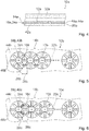
- the induction heating elements 12a are arranged below the hob plate 32a (cf. Fig. 4 ).
- the induction hob device 10a has a printed circuit board 44a (cf. Fig. 2 and 4 ).
- the printed circuit board 44a is formed in two layers in the present embodiment.
- the induction heating elements 12a are arranged on the printed circuit board 44a. Induction heating elements 12a arranged adjacent to one another are arranged on different layers of the printed circuit board 44a.
- the induction hob device 10a has a magnetic flux bundling unit 14a (cf. Fig. 2 to 4 ).
- the magnetic flux condensing unit 14a is provided for concentrating a magnetic flux provided by the induction heaters 12a.
- the magnetic flux bundling unit 14a concentrates a magnetic flux provided by induction heating elements 12a, which are in particular activated.
- the magnetic flux bundling unit 14a is associated with the overlapping induction heating elements 12a.
- the induction hob device 10a has a space divider element 42a (cf. Fig. 3 and 4 ).
- the room divider element 42a is formed in the present embodiment as a shielding element. In an assembled state, the room divider element 42a divides a storage space divided by the hob outer housing, within which, in particular, the induction heating elements 12a and the magnetic flux bundling unit 14a are arranged.
- the magnetic flux bundling unit 14a In an installed position, the magnetic flux bundling unit 14a is arranged above the room divider element 42a.
- the magnetic flux bundling unit 14a is mounted in a mounting position on the space divider element 42a.
- the printed circuit board 44a is arranged in an installed position above the magnetic flux bundling unit 14a and thus in particular above the room divider element 42a.
- the magnetic flux bundling unit 14a and the induction heating elements 12a are arranged in two spatially separated layers 18a, 20a (cf. Fig. 4 ).
- the magnetic flux bundling unit 14a has a plurality of magnetic flux bundling elements 16a (cf. Fig. 2 to 4 ). In each case one of the magnetic flux bundling elements 16a is associated with two of the overlapping induction heating elements 12a for flux bundling. Only one of the magnetic flux bundling elements 16a will be described below.
- the magnetic flux concentrating element 16a When viewed perpendicular to a main plane of extension of one of the induction heating elements 12a, the magnetic flux concentrating element 16a is located for the most part within an overlapping area of the induction heating elements 12a.
- the magnetic flux condensing element 16a is disposed on a main plane of extension of one of the induction heaters 12a along an imaginary connecting line 22a of centroids 38a and / or midpoints 40a of the induction heaters 12a when viewed perpendicularly.
- the magnetic flux bundling unit 14a has a plurality of further magnetic flux bundling elements 24a (cf. FIGS. 2 and 3 ).
- the magnetic flux bundling unit 14a has four further magnetic flux bundling elements 24a per induction heating element 12a. In the following, only one of the further magnetic flux bundling elements 24a will be described.
- the further magnetic flux bundling element 24a is associated with exactly one of the induction heating elements 12a in the present exemplary embodiment.
- the induction heating elements 12a are each assigned an identical number of magnetic flux bundling elements 16a, 24a.
- each of the induction heating elements 12a is associated with a number of six magnetic flux bundling elements 16a, 24a.
- each of the induction heating elements 12a is assigned a number of two magnetic flux bundling elements 16a and a number of four further magnetic flux bundling elements 24a.
- the magnetic flux bundling element 16a and the further magnetic flux bundling element 24a are formed substantially identical.
- the further magnetic flux bundling element 24a When viewed perpendicularly on a main extension plane of one of the induction heating elements 12a, the further magnetic flux bundling element 24a partially projects beyond the induction heating element 12a.
- the further magnetic flux bundling element 24a has a transfer portion 46a (cf. Fig. 2 ). When viewed perpendicular to a main extension plane of one of the induction heating elements 12a, the transfer portion 46a is disposed outside a surface defined by the induction heating element 12a to which the further magnetic flux bundling element 24a is associated.
- one of the induction heating elements 12a which are in particular activated, is provided magnetic flux bundled together, in particular by the magnetic flux bundling unit 14 a.
- FIG. 5 to 11 Further embodiments of the invention are shown. The following descriptions are essentially limited to the differences between the embodiments, with respect to the same components, features and functions on the description of the embodiment of Fig. 1 to 4 can be referenced. To distinguish the embodiments, the letter a in the reference numerals of the embodiment in the Fig. 1 to 4 by the letters b to h in the reference numerals of the embodiment of Fig. 5 to 11 replaced. With respect to identically designated components, in particular with regard to components with the same reference numerals, can in principle also to the drawings and / or the description of the embodiment of Fig. 1 to 4 to get expelled.
- FIG. 5 shows a further induction hob device 10b with a plurality of overlapping induction heating elements 12b, which are arranged in a row.
- a magnetic flux bundling unit 14b of the induction hob device 10b has a plurality of magnetic flux bundling elements 16b. In the following, only one of the magnetic flux bundling elements 16b will be described.
- the magnetic flux bundling element 16b which is associated with two adjacently disposed fluxing overlapping induction heating elements 12b, is disposed perpendicularly to a main plane of extension of one of the induction heating elements 12b along an imaginary connecting line 22b of centroids 38b and / or midpoints 40b of the induction heating elements 12b.
- the magnetic flux bundling unit 14b has a plurality of further magnetic flux bundling elements 24b.
- the magnetic flux bundling unit 14b has four further magnetic flux bundling elements 24b per induction heating element 12b. In the following, only one of the further magnetic flux bundling elements 24b will be described.
- the magnetic flux bundling element 16b has a longitudinal extent 26b, which differs from a longitudinal extent 28b of the further magnetic flux bundling element 24b.
- the longitudinal extension 26b of the magnetic flux bundling element 16b is greater than the longitudinal extent 28b of the further magnetic flux bundling element 24b.
- a large part of the further magnetic flux bundling elements 24b is associated with two overlapping induction heating elements 12b arranged adjacent to one another.
- all other magnetic flux bundling elements 24b are assigned two overlapping induction heating elements 12b arranged adjacent to one another.
- Fig. 6 shows another induction hob apparatus 10c with a plurality of overlapping induction heating elements 12c.
- a longitudinal extent 26c of a magnetic flux bundling element 16c of a magnetic flux bundling unit 14c is greater than a longitudinal extent 28c of a further magnetic flux bundling element 24c of the magnetic flux bundling unit 14c.
- the further magnetic flux bundling element 24c is associated with exactly one of the induction heating elements 12c in the present exemplary embodiment.
- the induction heating elements 12c are arranged in a row.
- Fig. 7 shows another induction hob apparatus 10d having a plurality of overlapping induction heating elements 12d.
- the induction heating elements 12d are arranged in the form of a matrix.
- the matrix corresponds to a regular mathematical matrix in which rows and columns are arranged in regular pattern unopposed relative to each other.
- a magnetic flux bundling unit 14d of the induction hob device 10d has a plurality of magnetic flux bundling elements 16d.
- the magnetic flux bundling elements 16d which are each associated with two adjacently arranged overlapping induction heating elements 12d for flux bundling, are arranged perpendicular to a main extension plane of one of the induction heating elements 12d along imaginary connecting lines 22d of centroids 38d and / or midpoints 40d of the induction heating elements 12d.
- the imaginary connecting lines 22d are aligned parallel to row vectors and column vectors of the matrix.
- the magnetic flux bundling element 16d has a longitudinal extent 26d, which differs from a longitudinal extent 28d of a further magnetic flux bundling element 24d of the magnetic flux bundling unit 14d.
- the induction heating 12d are arranged on a two-layer printed circuit board 44d.
- Fig. 8 shows another induction hob device 10e with a plurality of overlapping induction heating elements 12e.
- the induction heating elements 12e are arranged in the form of a matrix. When viewed perpendicular to a main extension plane of one of the induction heating elements 12e, the matrix has a substantially triangular shape.
- the induction heating elements 12e are arranged on a three-layer printed circuit board 44e.
- a magnetic flux bundling unit 14e of the induction hob device 10e has a plurality of magnetic flux bundling elements 16e.
- the magnetic flux bundling elements 16e which are each associated with two adjacently arranged overlapping induction heating elements 12e for flux bundling, are arranged perpendicular to a main extension plane of one of the induction heating elements 12e along imaginary connecting lines 22e of centroids 38e and / or midpoints 40e of the induction heating elements 12e.
- a part of the imaginary connecting lines 22e is aligned parallel to row vectors of the matrix.
- a part of the imaginary connecting lines 22e is oriented obliquely relative to row vectors and / or column vectors of the matrix.
- the connecting lines 22e, which are oriented obliquely relative to row vectors and / or to column vectors of the matrix, in the present exemplary embodiment include a least angle of substantially 60 ° with the row vectors of the matrix.
- the connecting lines 22e, which are oriented obliquely relative to row vectors and / or to column vectors of the matrix in the present exemplary embodiment include a least angle of substantially 30 ° with the column vectors of the matrix.
- the magnetic flux bundling elements 16e and further magnetic flux bundling elements 24e of the magnetic flux bundling unit 14e are formed substantially identically.
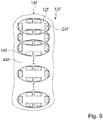
- Fig. 9 shows another induction hob apparatus 10f having a plurality of overlapping induction heating elements 12f arranged in a row.
- the induction heating elements 12f have a substantially elliptical shape when viewed perpendicularly on at least one main extension plane of one of the induction heating elements 12f.
- the induction heating elements 12f are arranged overlapping along their respective longitudinal sides.
- a series line along which the induction heating elements 12f are arranged adjacent to each other is aligned perpendicular to respective longitudinal extensions of the induction heating elements 12f.
- a magnetic flux bundling unit 14f of the induction hob device 10f has a plurality of magnetic flux condensing elements 16f. In each case two overlapping induction heating elements 12f are associated with two magnetic flux bundling elements 16f for flux bundling.
- the magnetic flux bundling unit 14f has a plurality of other magnetic flux bundling elements 24f.
- the further magnetic flux bundling elements 24f are each associated with exactly one of the induction heating elements 12f.
- Each of the induction heating elements 12f is associated with six magnetic flux bundling elements 16f, 24f.
- the magnetic flux bundling elements 16f and the other magnetic flux bundling elements 24f are formed substantially identically.
- Fig. 10 shows another induction hob apparatus 10g having a plurality of overlapping induction heating elements 12g arranged in the form of a regular matrix.
- Induction heating elements 12g which are surrounded by two induction heating elements 12g when viewed perpendicularly on a main extension plane of one of the induction heating elements 12g in the row and column in which they are arranged, are associated exclusively with magnetic flux bundling elements 16g which are associated with two overlapping induction heating elements 12g for flux bundling.
- At least one further magnetic flux bundling element 24g and a maximum of three further magnetic flux bundling elements 24g are assigned to induction heating elements 12g arranged at the edge depending on the position in the matrix.
- Fig. 11 shows a further induction hob apparatus 10h with a plurality of overlapping induction heating elements 12h, which are arranged in the form of a matrix. Adjacent columns of the matrix are offset relative to each other. The mutually offset columns of the matrix are in the present embodiment, when viewed perpendicular to a main extension plane of the induction heating 12h offset by half the transverse extent of the induction heating 12h offset from one another.
- a magnetic flux bundling unit 14h of the induction hob device 10h has a plurality of magnetic flux condensing elements 16h. A part of the magnetic flux condensing elements 16h is associated with two overlapping induction heating elements 12h. A part of the magnetic flux condensing elements 16h is associated with three overlapping induction heating elements 12h.
Landscapes
- Physics & Mathematics (AREA)
- Electromagnetism (AREA)
- Engineering & Computer Science (AREA)
- Computer Networks & Wireless Communication (AREA)
- Power Engineering (AREA)
- General Induction Heating (AREA)
- Near-Field Transmission Systems (AREA)
- Cookers (AREA)
Abstract
Description
- Die Erfindung betrifft eine Induktionskochfeldvorrichtung nach dem Oberbegriff des Anspruchs 1 und ein Verfahren zu einem Betrieb einer Induktionskochfeldvorrichtung nach dem Oberbegriff des Anspruchs 11.
- Aus der europäischen Patentanmeldung
EP 1 858 300 A1 ist bereits eine Induktionskochfeldvorrichtung mit einer Vielzahl von überlappenden Induktionsheizelementen bekannt. Die Induktionsheizelemente sind in mehreren Ebenen übereinander angeordnet. In jeder der Ebenen ist ein Teil der Induktionsheizelemente in Form einer Matrix koplanar relativ zueinander angeordnet. Für derartig überlappend angeordnete Induktionsheizelemente ist eine Anordnung von Magnetflussbündelungselementen einer Magnetflussbündelungseinheit, wie dies für den Fall von klassisch angeordneten Induktionsheizelementen bekannt ist, aufgrund der überlappenden Anordnung der Induktionsheizelemente nicht praktikabel. - Die Aufgabe der Erfindung besteht insbesondere darin, eine gattungsgemäße Vorrichtung vorteilhaft weiterzuentwickeln. Die Aufgabe wird erfindungsgemäß durch die Merkmale der Ansprüche 1 und 11 gelöst, während vorteilhafte Ausgestaltungen und Weiterbildungen der Erfindung den Unteransprüchen entnommen werden können.
- Die Erfindung geht aus von einer Induktionskochfeldvorrichtung mit zumindest zwei überlappenden Induktionsheizelementen.
- In einem Aspekt der Erfindung, welcher für sich allein genommen als auch in Kombination mit weiteren Aspekten der Erfindung betrachtet werden kann, wird vorgeschlagen, dass die Induktionskochfeldvorrichtung zumindest eine Magnetflussbündelungseinheit aufweist, die zu einer Bündelung zumindest eines von zumindest einem der Induktionsheizelemente bereitgestellten magnetischen Flusses vorgesehen ist und die zumindest ein Magnetflussbündelungselement aufweist, welches zur Flussbündelung den überlappenden Induktionsheizelementen zugeordnet ist.
- Durch die erfindungsgemäße Ausgestaltung kann eine gattungsgemäße Vorrichtung vorteilhaft weiterentwickelt werden. Aufgrund des den überlappenden Induktionsheizelementen zugeordneten Magnetflussbündelungselements kann insbesondere eine geringe Anzahl an Magnetflussbündelungselementen ermöglicht werden, wodurch insbesondere geringe Kosten und/oder ein geringes Gesamtgewicht und/oder ein geringer Bauraumbedarf, insbesondere eine geringe Bauhöhe, erzielt werden können. Insbesondere kann eine optimale Beheizung eines insbesondere aufgestellten Gargeschirrs ermöglicht werden, und zwar insbesondere aufgrund einer von der Magnetflussbündelungseinheit bewirkten optimalen Flussbündelung des von zumindest einem der Induktionsheizelemente bereitgestellten magnetischen Flusses. Im Fall von zumindest zwei überlappenden Induktionsheizelementen kann insbesondere durch das den überlappenden Induktionsheizelementen zugeordnete Magnetflussbündelungselement eine insbesondere negative Beeinflussung zwischen jeweils genau einem der Induktionsheizelemente zugeordneten Magnetflussbündelungselement und/oder eine unsymmetrische Beheizung eines insbesondere aufgestellten Gargeschirrs vermieden werden. Insbesondere kann eine Anwendung auf Kochfelder und vorteilhaft auf Matrixkochfeld mit überlappenden Induktionsheizelementen bewirkt werden. Insbesondere in Bezug auf eine Anordnung der Magnetflussbündelungseinheit kann insbesondere ein hoher Grad an Symmetrie erzielt werden, wodurch insbesondere eine gute Wärmeverteilung innerhalb eines insbesondere aufgestellten Gargeschirrs erreicht werden kann.
- Unter einer "Induktionskochfeldvorrichtung" soll insbesondere zumindest ein Teil, insbesondere eine Unterbaugruppe, eines Induktionskochfelds verstanden werden. Das Induktionsheizelement ist insbesondere dazu vorgesehen, ein elektromagnetisches Wechselfeld insbesondere mit einer Frequenz in einem Bereich von 20 kHz bis 100 kHz zu erzeugen, das insbesondere dazu vorgesehen ist, in einem aufgestellten, insbesondere metallischen, vorzugsweise ferromagnetischen Gargeschirrboden durch Wirbelstrominduktion und/oder Ummagnetisierungseffekte in Wärme umgewandelt zu werden. Insbesondere weist die Induktionskochfeldvorrichtung zumindest vier, insbesondere zumindest sechs, vorteilhaft zumindest acht, besonders vorteilhaft zumindest zehn, vorzugsweise zumindest zwölf und besonders bevorzugt eine Vielzahl von Induktionsheizelemente(n) auf.
- Unter zumindest zwei "überlappenden" Induktionsheizelementen soll insbesondere verstanden werden, dass ein erstes Induktionsheizelement der Induktionsheizelemente zumindest einen ersten Teilbereich und ein zweites Induktionsheizelement der Induktionsheizelemente zumindest einen zweiten Teilbereich aufweist, der bei einer senkrechten Betrachtung auf zumindest eine Haupterstreckungsebene wenigstens eines der Induktionsheizelemente mit dem ersten Teilbereich zusammenfällt und insbesondere in der Haupterstreckungsebene denselben Platz einnimmt wie der erste Teilbereich. Bei einer senkrechten Betrachtung auf zumindest eine Haupterstreckungsebene wenigstens eines der Induktionsheizelementesind der erste Teilbereich und der zweite Teilbereich insbesondere deckungsgleich zueinander angeordnet.
- Beispielsweise könnten die überlappenden Induktionsheizelemente wenigstens teilweise überlappend angeordnet sein. Bei einer senkrechten Betrachtung auf zumindest eine Haupterstreckungsebene wenigstens eines der Induktionsheizelemente könnte der erste Teilbereich insbesondere einen Anteil von mindestens 5 %, insbesondere von mindestens 10 %, vorteilhaft von mindestens 20 %, besonders vorteilhaft von mindestens 25 % und vorzugsweise von mindestens 30 % einer Flächenerstreckung des ersten Induktionsheizelements in der Haupterstreckungsebene aufweisen. Insbesondere könnte der zweite Teilbereich bei einer senkrechten Betrachtung auf zumindest eine Haupterstreckungsebene wenigstens eines der Induktionsheizelemente einen Anteil von mindestens 5 %, insbesondere von mindestens 10 %, vorteilhaft von mindestens 20 %, besonders vorteilhaft von mindestens 25 % und vorzugsweise von mindestens 30 % einer Flächenerstreckung des zweiten Induktionsheizelements in der Haupterstreckungsebene aufweisen. Ein Mittelpunkt und/oder Schwerpunkt des ersten Teilbereichs und ein Mittelpunkt und/oder Schwerpunkt des zweiten Teilbereichs könnte bei einer senkrechten Betrachtung auf zumindest eine Haupterstreckungsebene wenigstens eines der Induktionsheizelemente insbesondere einen Abstand von mindestens 15 %, insbesondere von mindestens 20 %, vorteilhaft von mindestens 25 % einer Längserstreckung eines kleineren der Induktionsheizelemente aufweisen. Ein Mittelpunkt und/oder Schwerpunkt des ersten Teilbereichs und ein Mittelpunkt und/oder Schwerpunkt des zweiten Teilbereichs könnten bei einer senkrechten Betrachtung auf zumindest eine Haupterstreckungsebene wenigstens eines der Induktionsheizelemente insbesondere einen Abstand von maximal 40 %, vorteilhaft von maximal 35 % und vorzugsweise von maximal 30 % einer Längserstreckung eines kleineren der Induktionsheizelemente aufweisen.
- Alternativ oder zusätzlich könnten die überlappenden Induktionsheizelemente wenigstens im Wesentlichen vollständig überlappend angeordnet sein. Bei einer senkrechten Betrachtung auf zumindest eine Haupterstreckungsebene wenigstens eines der Induktionsheizelemente könnte der erste Teilbereich insbesondere einen Anteil von mindestens 75 %, insbesondere von mindestens 80 %, vorteilhaft von mindestens 85 %, besonders vorteilhaft von mindestens 90 % und vorzugsweise von mindestens 95 % einer Flächenerstreckung des ersten Induktionsheizelements in der Haupterstreckungsebene aufweisen. Insbesondere könnte der zweite Teilbereich bei einer senkrechten Betrachtung auf zumindest eine Haupterstreckungsebene wenigstens eines der Induktionsheizelemente einen Anteil von mindestens 75 %, insbesondere von mindestens 80 %, vorteilhaft von mindestens 85 %, besonders vorteilhaft von mindestens 90 % und vorzugsweise von mindestens 95 % einer Flächenerstreckung des zweiten Induktionsheizelements in der Haupterstreckungsebene aufweisen. Ein Mittelpunkt und/oder Schwerpunkt des ersten Teilbereichs und ein Mittelpunkt und/oder Schwerpunkt des zweiten Teilbereichs könnten bei einer senkrechten Betrachtung auf zumindest eine Haupterstreckungsebene wenigstens eines der Induktionsheizelemente insbesondere einen Abstand von maximal 40 %, vorteilhaft von maximal 45 % und vorzugsweise von maximal 50 % einer Längserstreckung eines kleineren der Induktionsheizelemente aufweisen.
- Unter einer "Haupterstreckungsebene" eines Objekts soll insbesondere eine Ebene verstanden werden, welche parallel zu einer größten Seitenfläche eines kleinsten gedachten geometrischen Quaders ist, welcher das Objekt gerade noch vollständig umschließt, und insbesondere durch den Mittelpunkt des Quaders verläuft. Unter einer "Längserstreckung" eines Objekts soll insbesondere eine Erstreckung des Objekts entlang einer Längserstreckungsrichtung des Objekts verstanden werden. Unter einer "Längserstreckungsrichtung" eines Objekts soll insbesondere eine Richtung verstanden werden, welche parallel zu einer längsten Seite eines kleinsten gedachten geometrischen Quaders ausgerichtet ist, welcher das Objekt gerade noch vollständig umschließt. Unter einer "Erstreckung" eines Objekts soll insbesondere ein maximaler Abstand zweier Punkte einer senkrechten Projektion des Objekts auf eine Ebene verstanden werden.
- Beispielsweise könnten die Induktionsheizelemente bei einer senkrechten Betrachtung auf zumindest eine Haupterstreckungsebene wenigstens eines der Induktionsheizelemente eine wenigstens im Wesentlichen polygonale Gestalt aufweisen, wie beispielsweise eine wenigstens im Wesentlichen rechteckige und/oder quadratische und/oder n-eckige Gestalt. Vorteilhaft weisen die Induktionsheizelemente bei einer senkrechten Betrachtung auf zumindest eine Haupterstreckungsebene wenigstens eines der Induktionsheizelemente eine wenigstens im Wesentlichen ovale Gestalt auf. Die Induktionsheizelemente könnten bei einer senkrechten Betrachtung auf zumindest eine Haupterstreckungsebene wenigstens eines der Induktionsheizelemente eine wenigstens im Wesentlichen kreisförmige Gestalt aufweisen. Alternativ oder zusätzlich könnten die Induktionsheizelemente bei einer senkrechten Betrachtung auf zumindest eine Haupterstreckungsebene wenigstens eines der Induktionsheizelemente eine wenigstens im Wesentlichen ellipsenförmige Gestalt aufweisen.
- Die Induktionskochfeldvorrichtung könnte beispielsweise zumindest eine Leiterplatte aufweisen, an welcher die Induktionsheizelemente beispielsweise angeordnet sein könnten. Die Leiterplatte könnte insbesondere zumindest eine Lage aufweisen, an welcher die Induktionsheizelemente insbesondere angeordnet sind. Vorteilhaft könnte die Leiterplatte zumindest zwei und vorzugsweise zumindest drei Lagen aufweisen, an welchen die Induktionsheizelemente insbesondere angeordnet sind. Insbesondere könnten die Induktionsheizelemente auf die Leiterplatte und insbesondere auf die Lagen der Leiterplatte aufgedruckt sein.
- Alternativ oder zusätzlich könnten die Induktionsheizelemente jeweils zumindest eine Heizleitung aufweisen, welche sich insbesondere über verschiedene Ebenen erstrecken könnte. Beispielsweise könnte jedes Induktionsheizelement zumindest einen Spulenträger aufweisen, an welchem die entsprechende Heizleitung, insbesondere auf zwei einander gegenüberliegenden Seiten in Bezug auf eine Haupterstreckungsebene des Spulenträgers, gewickelt sein könnte.
- Die Magnetflussbündelungseinheit und insbesondere das Magnetflussbündelungselement besteht insbesondere wenigstens zu einem Großteil aus Ferriten, welche insbesondere ferromagnetische keramische Werkstoffe sind.
- Unter der Wendung, dass ein Magnetflussbündelungselement einem Induktionsheizelement "zugeordnet" ist, soll insbesondere verstanden werden, dass das Magnetflussbündelungselement in wenigstens einem Betriebszustand, in welchem das Induktionsheizelement insbesondere betrieben ist und insbesondere einen magnetischen Fluss bereitstellt, den von dem Induktionsheizelement bereitgestellten magnetischen Fluss wenigstens teilweise bündelt. Ein Magnetflussbündelungselement, welches insbesondere den überlappenden Induktionsheizelementen zugeordnet ist, bündelt in wenigstens einem Betriebszustand insbesondere wenigstens teilweise einen jeweiligen von sämtlichen sich in Betrieb befindenden Induktionsheizelementen der überlappenden Induktionsheizelemente, welchen das Magnetflussbündelungselement insbesondere zugeordnet ist, bereitgestellten magnetischen Fluss. Unter der Wendung, dass ein Magnetflussbündelungselement einen magnetischen Fluss "wenigstens teilweise" bündelt, soll insbesondere verstanden werden, dass das Magnetflussbündelungselement den magnetischen Fluss alleine bündelt oder dass das Magnetflussbündelungselement den magnetischen Fluss gemeinsam mit zumindest einem zweiten Magnetflussbündelungselement bündelt.
- Das den überlappenden Induktionsheizelementen zugeordnete Magnetflussbündelungselement ist insbesondere in einem Nahbereich zumindest eines der Induktionsheizelemente und vorteilhaft in einem Nahbereich eines jeden der überlappenden Induktionsheizelementen angeordnet. Bei einer senkrechten Betrachtung auf zumindest eine Haupterstreckungsebene wenigstens eines der Induktionsheizelemente ist das den überlappenden Induktionsheizelementen zugeordnete Magnetflussbündelungselement insbesondere wenigstens zu einem Großteil innerhalb einer von den überlappenden Induktionsheizelementen aufgespannten Fläche angeordnet. Das den überlappenden Induktionsheizelementen zugeordnete Magnetflussbündelungselement ist insbesondere frei von einer Sättigung. Unter "wenigstens zu einem Großteil" soll insbesondere zu einem Anteil von mindestens 70 %, insbesondere zu mindestens 80 %, vorteilhaft zu mindestens 90 % und vorzugsweise zu mindestens 95 % verstanden werden.
- Unter "vorgesehen" soll insbesondere speziell ausgelegt und/oder ausgestattet verstanden werden. Darunter, dass ein Objekt zu einer bestimmten Funktion vorgesehen ist, soll insbesondere verstanden werden, dass das Objekt diese bestimmte Funktion in zumindest einem Anwendungs- und/oder Betriebszustand erfüllt und/oder ausführt.
- In einem weiteren Aspekt der Erfindung, welcher für sich allein genommen als auch in Kombination mit weiteren Aspekten der Erfindung betrachtet werden kann, wird vorgeschlagen, dass die Induktionskochfeldvorrichtung zumindest eine Magnetflussbündelungseinheit, insbesondere die zuvor genannte Magnetflussbündelungseinheit, aufweist, die zu einer Bündelung zumindest eines von zumindest einem der Induktionsheizelemente bereitgestellten magnetischen Flusses vorgesehen ist, wobei die Magnetflussbündelungseinheit und die Induktionsheizelemente bezüglich zumindest einer Haupterstreckungsebene zumindest eines der Induktionsheizelemente in zumindest zwei räumlich voneinander getrennten Schichten angeordnet sind. Insbesondere sind die Schichten in wenigstens einem montierten Zustand wenigstens im Wesentlichen parallel zueinander angeordnet. In wenigstens einem montierten Zustand sind die Schichten insbesondere wenigstens im Wesentlichen parallel zu der Haupterstreckungsebene und/oder zu zumindest einer Kochfeldplatte angeordnet. Die Induktionskochfeldvorrichtung weist insbesondere zumindest eine Kochfeldplatte auf, welche insbesondere zu einem Aufstellen von Gargeschirr vorgesehen ist und insbesondere wenigstens zu einem Großteil aus Glas und/oder Glaskeramik besteht. Unter wenigstens "wenigstens im Wesentlichen parallel" soll hier insbesondere eine Ausrichtung einer Richtung relativ zu einer Bezugsrichtung, insbesondere in einer Ebene, verstanden werden, wobei die Richtung gegenüber der Bezugsrichtung eine Abweichung insbesondere kleiner als 8°, vorteilhaft kleiner als 5° und besonders vorteilhaft kleiner als 2° aufweist. Die Schichten sind insbesondere bezüglich zumindest einer Richtung, in welcher die Schichten insbesondere benachbart zueinander angeordnet sind, überlappungsfrei zueinander angeordnet. Ausgehend von zumindest einem Punkt innerhalb einer ersten der Schichten und bei Fortschreiten in zumindest einer Richtung, in welcher die Schichten insbesondere benachbart zueinander angeordnet sind, schneidet eine die Schichten verbindende Gerade insbesondere zunächst eine Begrenzung der ersten Schicht und anschließend eine Begrenzung einer zweiten der Schichten. Dadurch kann insbesondere eine einfache Montage erreicht werden. Insbesondere kann eine modulare Bauweise ermöglicht werden, wodurch insbesondere einzelne Komponenten separat gefertigt und/oder gekauft werden können.
- Zudem wird vorgeschlagen, dass das Magnetflussbündelungselement bei einer senkrechten Betrachtung auf zumindest eine Haupterstreckungsebene wenigstens eines der Induktionsheizelemente entlang einer gedachten Verbindungslinie von Schwerpunkten und/oder Mittelpunkten der Induktionsheizelemente angeordnet ist, wodurch insbesondere eine optimale Flussbündelung erzielt werden kann.
- Beispielsweise könnte die Magnetflussbündelungseinheit ausschließlich das den überlappenden Induktionsheizelementen zugeordnete Magnetflussbündelungselement aufweisen. Vorzugsweise weist die Magnetflussbündelungseinheit zumindest ein weiteres Magnetflussbündelungselement auf, welches zumindest einem der Induktionsheizelemente zugeordnet ist, wodurch insbesondere eine optimale Beheizung eines insbesondere aufgestellten Gargeschirrs erreicht werden kann.
- Das weitere Magnetflussbündelungselement könnte beispielsweise zumindest zwei, insbesondere überlappenden Induktionsheizelementen zugeordnet sein. Insbesondere könnte zumindest eines der überlappenden Induktionsheizelemente, welchen das weitere Magnetflussbündelungselement zugeordnet ist, identisch sein mit zumindest einem der überlappenden Induktionsheizelemente, welchen das Magnetflussbündelungselement zugeordnet ist. Insbesondere könnte zumindest eines der überlappenden Induktionsheizelemente, welchen das weitere Magnetflussbündelungselement zugeordnet ist, verschieden sein zu zumindest einem der überlappenden Induktionsheizelemente, welchen das Magnetflussbündelungselement zugeordnet ist. Vorzugsweise ist das weitere Magnetflussbündelungselement genau einem der Induktionsheizelemente zugeordnet. Dadurch kann insbesondere gezielt auf örtliche Gegebenheiten und/oder Gestalten von Induktionsheizelementen eingegangen werden, wodurch insbesondere eine hohe Flexibilität und/oder eine optimierte Flussbündelung ermöglicht werden kann.
- Zudem wird vorgeschlagen, dass den Induktionsheizelementen jeweils eine identische Anzahl an Magnetflussbündelungselementen zugeordnet ist. Insbesondere entspricht eine Anzahl an Magnetflussbündelungselementen, welche einem ersten Induktionsheizelement der Induktionsheizelemente zugeordnet ist, einer Anzahl an Magnetflussbündelungselementen, welche einem von dem ersten verschiedenen zweiten Induktionsheizelement der Induktionsheizelemente zugeordnet ist. Dadurch kann insbesondere eine gleichmäßige Beheizung eines insbesondere aufgestellten Gargeschirrs erreicht und/oder eine automatisierte Fertigung und/oder Montage ermöglicht werden.
- Weiterhin wird vorgeschlagen, dass das Magnetflussbündelungselement eine Längserstreckung aufweist, welche sich von einer Längserstreckung des weiteren Magnetflussbündelungselements unterscheidet. Beispielsweise könnte die Längserstreckung des Magnetflussbündelungselements kleiner sein als die Längserstreckung des weiteren Magnetflussbündelungselements. Insbesondere könnte die Längserstreckung des Magnetflussbündelungselements größer sein als die Längserstreckung des weiteren Magnetflussbündelungselements. Unter der Wendung, dass sich die Längserstreckung des Magnetflussbündelungselements von der Längserstreckung des weiteren Magnetflussbündelungselements "unterscheidet", soll insbesondere verstanden werden, dass eine erste Längserstreckung der Längserstreckungen größer ist als eine zweite Längserstreckung der Längserstreckungen, wobei insbesondere ein Quotient aus der zweiten Längserstreckung und der ersten Längserstreckung einen Wert von maximal 0,9, insbesondere von maximal 0,85, vorteilhaft von maximal 0,8, besonders vorteilhaft von maximal 0,7 und vorzugsweise von maximal 0,6 annimmt. Dadurch können den Induktionsheizelementen insbesondere besonders flexibel und nach Bedarf Magnetflussbündelungselemente mit bedarfsgerechter Längserstreckung zugeordnet werden, wodurch der von dem entsprechenden Induktionsheizelement bereitgestellte Fluss optimal gebündelt werden kann.
- Ferner wird vorgeschlagen, dass das Magnetflussbündelungselement und das weitere Magnetflussbündelungselement wenigstens im Wesentlichen identisch ausgebildet sind. Das Magnetflussbündelungselement und das weitere Magnetflussbündelungselement weisen insbesondere eine wenigstens im Wesentlichen gleiche Form und/oder Gestalt auf. Insbesondere weist das Magnetflussbündelungselement eine Erstreckung in zumindest einer Erstreckungsrichtung auf, welche einer weiteren Erstreckung des weiteren Magnetflussbündelungselements in der Erstreckungsrichtung wenigstens im Wesentlichen entspricht. Ein Quotient aus einer kürzeren der Erstreckungen und einer längeren der Erstreckungen beträgt insbesondere mindestens 0,92, vorteilhaft mindestens 0,95, besonders vorteilhaft mindestens 0,97 und vorzugsweise mindestens 0,99. Die Erstreckung könnte insbesondere eine Längserstreckung und/oder eine Quererstreckung und/oder eine Dicke sein. Dadurch kann insbesondere eine geringe Lagerhaltung erreicht werden.
- Das weitere Magnetflussbündelungselement könnte bei einer senkrechten Betrachtung auf zumindest eine Haupterstreckungsebene wenigstens eines der Induktionsheizelemente beispielsweise innerhalb einer von dem Induktionsheizelement, welchem das weitere Magnetflussbündelungselement insbesondere zugeordnet sein könnte, aufgespannten Fläche angeordnet sein. Vorteilhaft überragt das weitere Magnetflussbündelungselement das Induktionsheizelement, welchem das weitere Magnetflussbündelungselement insbesondere zugeordnet ist, bei einer senkrechten Betrachtung auf zumindest eine Haupterstreckungsebene wenigstens eines der Induktionsheizelemente wenigstens teilweise. Insbesondere weist das weitere Magnetflussbündelungselement zumindest einen Überragungsteilbereich auf, welcher bei einer senkrechten Betrachtung auf zumindest eine Haupterstreckungsebene wenigstens eines der Induktionsheizelemente insbesondere außerhalb einer von dem Induktionsheizelement, welchem das weitere Magnetflussbündelungselement insbesondere zugeordnet ist, aufgespannten Fläche angeordnet ist. Insbesondere nimmt der Überragungsteilbereich einen Massenanteil und/oder Volumenanteil des Magnetflussbündelungselements von maximal 20 %, insbesondere von maximal 15 %, vorteilhaft von maximal 10 %, besonders vorteilhaft von maximal 5 % und vorzugsweise von maximal 2 % an. Insbesondere ist das Magnetflussbündelungselement bei einer senkrechten Betrachtung auf zumindest eine Haupterstreckungsebene wenigstens eines der Induktionsheizelemente wenigstens zu einem Großteil innerhalb einer von dem Induktionsheizelement, welchem das weitere Magnetflussbündelungselement insbesondere zugeordnet ist, aufgespannten Fläche angeordnet. Dadurch kann insbesondere ein von dem Induktionsheizelement bereitgestellter magnetischer Fluss besonders effektiv gebündelt werden.
- Eine gattungsgemäße Vorrichtung kann insbesondere besonders vorteilhat weiterentwickelt werden durch ein Verfahren zu einem Betrieb einer Induktionskochfeldvorrichtung mit zumindest zwei überlappenden Induktionsheizelementen, wobei ein von den Induktionsheizelementen bereitgestellter magnetischer Fluss gemeinsam gebündelt wird.
- Die Induktionskochfeldvorrichtung soll hierbei nicht auf die oben beschriebene Anwendung und Ausführungsform beschränkt sein. Insbesondere kann die Induktionskochfeldvorrichtung zu einer Erfüllung einer hierin beschriebenen Funktionsweise eine von einer hierin genannten Anzahl von einzelnen Elementen, Bauteilen und Einheiten abweichende Anzahl aufweisen.
- Weitere Vorteile ergeben sich aus der folgenden Zeichnungsbeschreibung. In der Zeichnung sind Ausführungsbeispiele der Erfindung dargestellt. Die Zeichnung, die Beschreibung und die Ansprüche enthalten zahlreiche Merkmale in Kombination. Der Fachmann wird die Merkmale zweckmäßigerweise auch einzeln betrachten und zu sinnvollen weiteren Kombinationen zusammenfassen.
- Es zeigen:
- Fig. 1
- ein Induktionskochfeld mit einer Induktionskochfeldvorrichtung in einer schematischen Draufsicht,
- Fig. 2
- überlappende Induktionsheizelemente und eine Magnetflussbündelungseinheit der Induktionskochfeldvorrichtung in einer schematischen Draufsicht auf eine Haupterstreckungsebene der Induktionsheizelemente, wobei Magnetflussbündelungselemente der Magnetflussbündelungseinheit, welche zumindest zwei Induktionsheizelementen zugeordnet sind, in den Figuren mit einer einfachen Linienschraffur und Magnetflussbündelungselemente, welche genau einem der Induktionsheizelemente zugeordnet sind, mit einer doppelten Linienschraffur gekennzeichnet sind,
- Fig. 3
- die Magnetflussbündelungseinheit und ein Raumteilerelement der Induktionskochfeldvorrichtung in einer schematischen Draufsicht,
- Fig. 4
- einen Ausschnitt der Induktionskochfeldvorrichtung in einer schematischen Schnittdarstellung,
- Fig. 5
- eine alternative Induktionskochfeldvorrichtung in einer schematischen Draufsicht,
- Fig. 6
- eine weitere alternative Induktionskochfeldvorrichtung in einer schematischen Draufsicht,
- Fig. 7
- eine weitere alternative Induktionskochfeldvorrichtung in einer schematischen Draufsicht,
- Fig. 8
- eine weitere alternative Induktionskochfeldvorrichtung in einer schematischen Draufsicht,
- Fig. 9
- eine weitere alternative Induktionskochfeldvorrichtung in einer schematischen Draufsicht,
- Fig. 10
- eine weitere alternative Induktionskochfeldvorrichtung in einer schematischen Draufsicht und
- Fig. 11
- eine weitere alternative Induktionskochfeldvorrichtung in einer schematischen Draufsicht.
-
Fig. 1 zeigt ein Induktionskochfeld 30a mit einer Induktionskochfeldvorrichtung 10a. Die Induktionskochfeldvorrichtung 10a weist eine Kochfeldplatte 32a auf. In einem montierten Zustand bildet die Kochfeldplatte 32a einen Teil eines Kochfeldaußengehäuses, insbesondere des Induktionskochfelds 30a, aus. Die Kochfeldplatte 32a bildet in einer Einbaulage einen einem Bediener zugewandten Teil des Kochfeldaußengehäuses aus. In einem montierten Zustand ist die Kochfeldplatte 32a zu einem Aufstellen von Gargeschirr vorgesehen. - Die Induktionskochfeldvorrichtung 10a weist eine Bedienerschnittstelle 34 zu einer Eingabe und/oder Auswahl von Betriebsparametern (vgl.
Fig. 1 ), beispielsweise einer Heizleistung und/oder einer Heizleistungsdichte und/oder einer Heizzone auf. Die Bedienerschnittstelle 34a ist zu einer Ausgabe eines Werts eines Betriebsparameters an einen Bediener vorgesehen. Beispielsweise könnte die Bedienerschnittstelle 34a den Wert des Betriebsparameters an einen Bediener optisch und/oder akustisch ausgeben. - Die Induktionskochfeldvorrichtung 10a weist eine Steuereinheit 36a auf. Die Steuereinheit 36a ist dazu vorgesehen, in Abhängigkeit von mittels der Bedienerschnittstelle 34a eingegebenen Betriebsparametern Aktionen auszuführen und/oder Einstellungen zu verändern.
- Die Induktionskochfeldvorrichtung 10a weist eine Vielzahl von überlappenden Induktionsheizelementen 12a auf (vgl.
Fig. 2 ). Von mehrfach vorhandenen Objekten ist in den Figuren jeweils lediglich eines mit einem Bezugszeichen versehen. - Im vorliegenden Ausführungsbeispiel sind die Induktionsheizelemente 12a in einer Reihe angeordnet. Alternativ könnten die Induktionsheizelemente 12a in Form einer Matrix angeordnet sein. Die Induktionsheizelemente 12a weisen im vorliegenden Ausführungsbeispiel bei einer senkrechten Betrachtung auf zumindest eine Haupterstreckungsebene eines der Induktionsheizelemente 12a eine im Wesentlichen kreisförmige Gestalt auf.
- Die Induktionskochfeldvorrichtung 10a könnte beispielsweise zusätzlich zu den überlappenden Induktionsheizelementen 12a zumindest ein weiteres Induktionsheizelement (nicht dargestellt) aufweisen, welches insbesondere überlappungsfrei zu den überlappenden Induktionsheizelementen 12a angeordnet sein könnte.
- Die Induktionsheizelemente 12a sind dazu vorgesehen, auf der Kochfeldplatte 32a oberhalb der Induktionsheizelemente 12a aufgestelltes Gargeschirr zu erhitzen. In einem Betriebszustand stellen die Induktionsheizelemente 12a, welche insbesondere aktiviert sind, einen magnetischen Fluss bereit, welcher insbesondere zu einer Erhitzung von aufgestelltem Gargeschirr vorgesehen ist. Die Induktionsheizelemente 12a, welche insbesondere aktiviert sind, führen in einem Betriebszustand aufgestelltem Gargeschirr, insbesondere mittels des von den Induktionsheizelementen bereitgestellten magnetischen Flusses, Energie zu. Die Steuereinheit 32a regelt in einem Betriebszustand eine Energiezufuhr zu den insbesondere aktivierten Induktionsheizelementen 12a. In einer Einbaulage sind die Induktionsheizelemente 12a unterhalb der Kochfeldplatte 32a angeordnet (vgl.
Fig. 4 ). - Die Induktionskochfeldvorrichtung 10a weist eine Leiterplatte 44a auf (vgl.
Fig. 2 und4 ). Die Leiterplatte 44a ist im vorliegenden Ausführungsbeispiel zweilagig ausgebildet. Die Induktionsheizelemente 12a sind an der Leiterplatte 44a angeordnet. Zueinander benachbart angeordnete Induktionsheizelemente 12a sind auf verschiedenen Lagen der Leiterplatte 44a angeordnet. - Die Induktionskochfeldvorrichtung 10a weist eine Magnetflussbündelungseinheit 14a auf (vgl.
Fig. 2 bis 4 ). Die Magnetflussbündelungseinheit 14a ist zu einer Bündelung eines von den Induktionsheizelementen 12a bereitgestellten magnetischen Flusses vorgesehen. In einem Betriebszustand bündelt die Magnetflussbündelungseinheit 14a einen von Induktionsheizelementen 12a, welche insbesondere aktiviert sind, bereitgestellten magnetischen Fluss. Die Magnetflussbündelungseinheit 14a ist den überlappenden Induktionsheizelementen 12a zugeordnet. - Die Induktionskochfeldvorrichtung 10a weist ein Raumteilerelement 42a auf (vgl.
Fig. 3 und4 ). Das Raumteilerelement 42a ist im vorliegenden Ausführungsbeispiel als ein Abschirmelement ausgebildet. In einem montierten Zustand unterteilt das Raumteilerelement 42a einen von dem Kochfeldaußengehäuse unterteilten Lagerraum, innerhalb welchem insbesondere die Induktionsheizelemente 12a und die Magnetflussbündelungseinheit 14a angeordnet sind. - In einer Einbaulage ist die Magnetflussbündelungseinheit 14a oberhalb des Raumteilerelements 42a angeordnet. Die Magnetflussbündelungseinheit 14a ist in einer Einbaulage auf dem Raumteilerelement 42a befestigt. Die Leiterplatte 44a ist in einer Einbaulage oberhalb der Magnetflussbündelungseinheit 14a und damit insbesondere oberhalb des Raumteilerelements 42a angeordnet. Bezüglich einer Haupterstreckungsebene eines der Induktionsheizelemente 12a sind die Magnetflussbündelungseinheit 14a und die Induktionsheizelemente 12a in zwei räumlich voneinander getrennten Schichten 18a, 20a angeordnet (vgl.
Fig. 4 ). - Die Magnetflussbündelungseinheit 14a weist mehrere Magnetflussbündelungselemente 16a auf (vgl.
Fig. 2 bis 4 ). Jeweils eines der Magnetflussbündelungselemente 16a ist zur Flussbündelung zweien der überlappenden Induktionsheizelemente 12a zugeordnet. Im Folgenden wird lediglich eines der Magnetflussbündelungselemente 16a beschrieben. - Bei einer senkrechten Betrachtung auf eine Haupterstreckungsebene eines der Induktionsheizelemente 12a ist das Magnetflussbündelungselement 16a zu einem Großteil innerhalb eines Überlappungsbereichs der Induktionsheizelemente 12a angeordnet. Das Magnetflussbündelungselement 16a ist bei einer senkrechten Betrachtung auf eine Haupterstreckungsebene eines der Induktionsheizelemente 12a entlang einer gedachten Verbindungslinie 22a von Schwerpunkten 38a und/oder Mittelpunkten 40a der Induktionsheizelemente 12a angeordnet.
- Die Magnetflussbündelungseinheit 14a weist eine Vielzahl von weiteren Magnetflussbündelungselementen 24a auf (vgl.
Fig. 2 und 3 ). Im vorliegenden Ausführungsbeispiel weist die Magnetflussbündelungseinheit 14a pro Induktionsheizelement 12a vier weitere Magnetflussbündelungselemente 24a auf. Im Folgenden wird lediglich eines der weiteren Magnetflussbündelungselemente 24a beschrieben. - Das weitere Magnetflussbündelungselement 24a ist im vorliegenden Ausführungsbeispiel genau einem der Induktionsheizelemente 12a zugeordnet. Den Induktionsheizelementen 12a ist jeweils eine identische Anzahl an Magnetflussbündelungselementen 16a, 24a zugeordnet. Im vorliegenden Ausführungsbeispiel ist jedem der Induktionsheizelemente 12a eine Anzahl von sechs Magnetflussbündelungselementen 16a, 24a zugeordnet. Jedem der Induktionsheizelemente 12a ist im vorliegenden Ausführungsbeispiel eine Anzahl von zwei Magnetflussbündelungselementen 16a und eine Anzahl von vier weiteren Magnetflussbündelungselementen 24a zugeordnet.
- Im vorliegenden Ausführungsbeispiel sind das Magnetflussbündelungselement 16a und das weitere Magnetflussbündelungselement 24a im Wesentlichen identisch ausgebildet.
- Bei einer senkrechten Betrachtung auf eine Haupterstreckungsebene eines der Induktionsheizelemente 12a überragt das weitere Magnetflussbündelungselement 24a das Induktionsheizelement 12a teilweise. Das weitere Magnetflussbündelungselement 24a weist einen Überragungsteilbereich 46a auf (vgl.
Fig. 2 ). Bei einer senkrechten Betrachtung auf eine Haupterstreckungsebene eines der Induktionsheizelemente 12a ist der Überragungsteilbereich 46a außerhalb einer von dem Induktionsheizelement 12a, welchem das weitere Magnetflussbündelungselement 24a zugeordnet ist, aufgespannten Fläche angeordnet. - In einem Verfahren zu einem Betrieb einer Induktionskochfeldvorrichtung 10a wird ein von den Induktionsheizelementen 12a, welche insbesondere aktiviert sind, bereitgestellter magnetischer Fluss gemeinsam gebündelt, und zwar insbesondere durch die Magnetflussbündelungseinheit 14a.
- In
Fig. 5 bis 11 sind weitere Ausführungsbeispiele der Erfindung gezeigt. Die nachfolgenden Beschreibungen beschränken sich im Wesentlichen auf die Unterschiede zwischen den Ausführungsbeispielen, wobei bezüglich gleich bleibender Bauteile, Merkmale und Funktionen auf die Beschreibung des Ausführungsbeispiels derFig. 1 bis 4 verwiesen werden kann. Zur Unterscheidung der Ausführungsbeispiele ist der Buchstabe a in den Bezugszeichen des Ausführungsbeispiels in denFig. 1 bis 4 durch die Buchstaben b bis h in den Bezugszeichen des Ausführungsbeispiels derFig. 5 bis 11 ersetzt. Bezüglich gleich bezeichneter Bauteile, insbesondere in Bezug auf Bauteile mit gleichen Bezugszeichen, kann grundsätzlich auch auf die Zeichnungen und/oder die Beschreibung des Ausführungsbeispiels derFig. 1 bis 4 verwiesen werden. -
Fig. 5 zeigt eine weitere Induktionskochfeldvorrichtung 10b mit einer Vielzahl von überlappenden Induktionsheizelementen 12b, welche in einer Reihe angeordnet sind. Eine Magnetflussbündelungseinheit 14b der Induktionskochfeldvorrichtung 10b weist mehrere Magnetflussbündelungselemente 16b auf. Im Folgenden wird lediglich eines der Magnetflussbündelungselemente 16b beschrieben. - Das Magnetflussbündelungselement 16b, welches zwei benachbart angeordneten überlappenden Induktionsheizelementen 12b zur Flussbündelung zugeordnet ist, ist bei einer senkrechten Betrachtung auf eine Haupterstreckungsebene eines der Induktionsheizelemente 12b entlang einer gedachten Verbindungslinie 22b von Schwerpunkten 38b und/oder Mittelpunkten 40b der Induktionsheizelemente 12b angeordnet.
- Die Magnetflussbündelungseinheit 14b weist eine Vielzahl von weiteren Magnetflussbündelungselementen 24b auf. Im vorliegenden Ausführungsbeispiel weist die Magnetflussbündelungseinheit 14b pro Induktionsheizelement 12b vier weitere Magnetflussbündelungselemente 24b auf. Im Folgenden wird lediglich eines der weiteren Magnetflussbündelungselemente 24b beschrieben.
- Das Magnetflussbündelungselement 16b weist eine Längserstreckung 26b auf, welche sich von einer Längserstreckung 28b des weiteren Magnetflussbündelungselements 24b unterscheidet. Die Längserstreckung 26b des Magnetflussbündelungselements 16b ist größer als die Längserstreckung 28b des weiteren Magnetflussbündelungselements 24b. Ein Großteil der weiteren Magnetflussbündelungselemente 24b ist im vorliegenden Ausführungsbeispiel zwei benachbart zueinander angeordneten überlappenden Induktionsheizelementen 12b zugeordnet. Mit Ausnahme von vier weiteren Magnetflussbündelungselementen 24b, von welchen jeweils zwei genau einem der randseitigen Induktionsheizelemente 12b zugeordnet sind, sind alle weiteren Magnetflussbündelungselemente 24b zwei benachbart zueinander angeordneten überlappenden Induktionsheizelemente 12b zugeordnet.
-
Fig. 6 zeigt eine weitere Induktionskochfeldvorrichtung 10c mit einer Vielzahl von überlappenden Induktionsheizelementen 12c. Eine Längserstreckung 26c eines Magnetflussbündelungselements 16c einer Magnetflussbündelungseinheit 14c ist größer als eine Längserstreckung 28c eines weiteren Magnetflussbündelungselements 24c der Magnetflussbündelungseinheit 14c. Das weitere Magnetflussbündelungselement 24c ist im vorliegenden Ausführungsbeispiel genau einem der Induktionsheizelemente 12c zugeordnet. Im vorliegenden Ausführungsbeispiel sind die Induktionsheizelemente 12c in einer Reihe angeordnet. -
Fig. 7 zeigt eine weitere Induktionskochfeldvorrichtung 10d mit einer Vielzahl von überlappenden Induktionsheizelementen 12d. Die Induktionsheizelemente 12d sind in Form einer Matrix angeordnet. Die Matrix entspricht einer regulären mathematischen Matrix, in welcher Zeilen und Spalten in regulärem Muster unversetzt relativ zueinander angeordnet sind. Eine Magnetflussbündelungseinheit 14d der Induktionskochfeldvorrichtung 10d weist mehrere Magnetflussbündelungselemente 16d auf. - Die Magnetflussbündelungselemente 16d, welche jeweils zwei benachbart angeordneten überlappenden Induktionsheizelementen 12d zur Flussbündelung zugeordnet sind, sind bei einer senkrechten Betrachtung auf eine Haupterstreckungsebene eines der Induktionsheizelemente 12d entlang von gedachten Verbindungslinien 22d von Schwerpunkten 38d und/oder Mittelpunkten 40d der Induktionsheizelemente 12d angeordnet. Die gedachten Verbindungslinien 22d sind parallel zu Zeilenvektoren und Spaltenvektoren der Matrix ausgerichtet.
- Das Magnetflussbündelungselement 16d weist eine Längserstreckung 26d auf, welche sich von einer Längserstreckung 28d eines weiteren Magnetflussbündelungselements 24d der Magnetflussbündelungseinheit 14d unterscheidet. Im vorliegenden Ausführungsbeispiel sind die Induktionsheizelemente 12d an einer zweilagig ausgebildeten Leiterplatte 44d angeordnet.
-
Fig. 8 zeigt eine weitere Induktionskochfeldvorrichtung 10e mit einer Vielzahl von überlappenden Induktionsheizelementen 12e. Die Induktionsheizelemente 12e sind in Form einer Matrix angeordnet. Bei einer senkrechten Betrachtung auf eine Haupterstreckungsebene eines der Induktionsheizelemente 12e weist die Matrix eine im Wesentlichen dreieckige Gestalt auf. Im vorliegenden Ausführungsbeispiel sind die Induktionsheizelemente 12e an einer dreilagig ausgebildeten Leiterplatte 44e angeordnet. - Eine Magnetflussbündelungseinheit 14e der Induktionskochfeldvorrichtung 10e weist mehrere Magnetflussbündelungselemente 16e auf. Die Magnetflussbündelungselemente 16e, welche jeweils zwei benachbart angeordneten überlappenden Induktionsheizelementen 12e zur Flussbündelung zugeordnet sind, sind bei einer senkrechten Betrachtung auf eine Haupterstreckungsebene eines der Induktionsheizelemente 12e entlang von gedachten Verbindungslinien 22e von Schwerpunkten 38e und/oder Mittelpunkten 40e der Induktionsheizelemente 12e angeordnet.
- Ein Teil der gedachten Verbindungslinien 22e ist parallel zu Zeilenvektoren der Matrix ausgerichtet. Ein Teil der gedachten Verbindungslinien 22e ist schräg relativ zu Zeilenvektoren und/oder zu Spaltenvektoren der Matrix ausgerichtet. Die Verbindungslinien 22e, welche schräg relativ zu Zeilenvektoren und/oder zu Spaltenvektoren der Matrix ausgerichtet sind, schließen im vorliegenden Ausführungsbeispiel mit den Zeilenvektoren der Matrix einen kleinsten Winkel von im Wesentlichen 60° ein. Die Verbindungslinien 22e, welche schräg relativ zu Zeilenvektoren und/oder zu Spaltenvektoren der Matrix ausgerichtet sind, schließen im vorliegenden Ausführungsbeispiel mit den Spaltenvektoren der Matrix einen kleinsten Winkel von im Wesentlichen 30° ein.
- Im vorliegenden Ausführungsbeispiel sind die Magnetflussbündelungselemente 16e und weitere Magnetflussbündelungselemente 24e der Magnetflussbündelungseinheit 14e im Wesentlichen identisch ausgebildet.
-
Fig. 9 zeigt eine weitere Induktionskochfeldvorrichtung 10f mit einer Vielzahl von überlappenden Induktionsheizelementen 12f, welche in einer Reihe angeordnet sind. Die Induktionsheizelemente 12f weisen im vorliegenden Ausführungsbeispiel bei einer senkrechten Betrachtung auf zumindest eine Haupterstreckungsebene eines der Induktionsheizelemente 12f eine im Wesentlichen ellipsenförmige Gestalt auf. - Die Induktionsheizelemente 12f sind entlang ihrer jeweiligen Längsseiten überlappend angeordnet. Eine Reihenlinie, entlang welcher die Induktionsheizelemente 12f benachbart zueinander angeordnet sind, ist senkrecht zu jeweiligen Längserstreckungen der Induktionsheizelemente 12f ausgerichtet.
- Eine Magnetflussbündelungseinheit 14f der Induktionskochfeldvorrichtung 10f weist mehrere Magnetflussbündelungselemente 16f auf. Jeweils zwei überlappenden Induktionsheizelementen 12f sind zwei Magnetflussbündelungselemente 16f zur Flussbündelung zugeordnet.
- Die Magnetflussbündelungseinheit 14f weist eine Vielzahl von weiteren Magnetflussbündelungselementen 24f auf. Die weiteren Magnetflussbündelungselemente 24f sind jeweils genau einem der Induktionsheizelemente 12f zugeordnet. Jedem der Induktionsheizelemente 12f sind sechs Magnetflussbündelungselemente 16f, 24f zugeordnet. Im vorliegenden Ausführungsbeispiel sind die Magnetflussbündelungselemente 16f und die weiteren Magnetflussbündelungselemente 24f im Wesentlichen identisch ausgebildet.
-
Fig. 10 zeigt eine weitere Induktionskochfeldvorrichtung 10g mit einer Vielzahl von überlappenden Induktionsheizelementen 12g, welche in Form einer regulären Matrix angeordnet sind. Induktionsheizelemente 12g, welche bei einer senkrechten Betrachtung auf eine Haupterstreckungsebene eines der Induktionsheizelemente 12g in der Zeile und Spalte, in der sie angeordnet sind, von zwei Induktionsheizelementen 12g umgeben sind, sind ausschließlich Magnetflussbündelungselementen 16g zugeordnet, welche zur Flussbündelung zwei überlappenden Induktionsheizelementen 12g zugeordnet sind. - Bei einer senkrechten Betrachtung auf eine Haupterstreckungsebene eines der Induktionsheizelemente 12g sind randseitig angeordneten Induktionsheizelementen 12g je nach Position in der Matrix zumindest ein weiteres Magnetflussbündelungselement 24g und maximal drei weitere Magnetflussbündelungselemente 24g zugeordnet.
-
Fig. 11 zeigt eine weitere Induktionskochfeldvorrichtung 10h mit einer Vielzahl von überlappenden Induktionsheizelementen 12h, welche in Form einer Matrix angeordnet sind. Benachbart zueinander angeordnete Spalten der Matrix sind versetzt relativ zueinander angeordnet. Die versetzt zueinander angeordneten Spalten der Matrix sind im vorliegenden Ausführungsbeispiel bei einer senkrechten Betrachtung auf eine Haupterstreckungsebene eines der Induktionsheizelemente 12h um eine halbe Quererstreckung der Induktionsheizelemente 12h versetzt zueinander angeordnet. - Eine Magnetflussbündelungseinheit 14h der Induktionskochfeldvorrichtung 10h weist eine Vielzahl von Magnetflussbündelungselementen 16h auf. Ein Teil der Magnetflussbündelungselemente 16h ist zwei überlappenden Induktionsheizelementen 12h zugeordnet. Ein Teil der Magnetflussbündelungselemente 16h ist drei überlappenden Induktionsheizelementen 12h zugeordnet.
-
- 10
- Induktionskochfeldvorrichtung
- 12
- Induktionsheizelement
- 14
- Magnetflussbündelungseinheit
- 16
- Magnetflussbündelungselement
- 18
- Schicht
- 20
- Schicht
- 22
- Verbindungslinie
- 24
- Weiteres Magnetflussbündelungselement
- 26
- Längserstreckung
- 28
- Längserstreckung
- 30
- Induktionskochfeld
- 32
- Kochfeldplatte
- 34
- Bedienerschnittstelle
- 36
- Steuereinheit
- 38
- Schwerpunkt
- 40
- Mittelpunkt
- 42
- Raumteilerelement
- 44
- Leiterplatte
- 46
- Überragungsteilbereich
Claims (11)
- Induktionskochfeldvorrichtung mit zumindest zwei überlappenden Induktionsheizelementen (12a-h), gekennzeichnet durch zumindest eine Magnetflussbündelungseinheit (14a-h), die zu einer Bündelung zumindest eines von zumindest einem der Induktionsheizelemente (12a-h) bereitgestellten magnetischen Flusses vorgesehen ist und die zumindest ein Magnetflussbündelungselement (16a-h) aufweist, welches zur Flussbündelung den überlappenden Induktionsheizelementen (12a-h) zugeordnet ist.
- Induktionskochfeldvorrichtung nach dem Oberbegriff des Anspruchs 1 und insbesondere nach Anspruch 1, gekennzeichnet durch zumindest eine Magnetflussbündelungseinheit (14a-h), die zu einer Bündelung zumindest eines von zumindest einem der Induktionsheizelemente (12a-h) bereitgestellten magnetischen Flusses vorgesehen ist, wobei die Magnetflussbündelungseinheit (14a-h) und die Induktionsheizelemente (12a-h) bezüglich zumindest einer Haupterstreckungsebene zumindest eines der Induktionsheizelemente (12a-h) in zumindest zwei räumlich voneinander getrennten Schichten (18a-h, 20a-h) angeordnet sind.
- Induktionskochfeldvorrichtung nach Anspruch 1 oder 2, dadurch gekennzeichnet, dass das Magnetflussbündelungselement (16a-e) bei einer senkrechten Betrachtung auf zumindest eine Haupterstreckungsebene wenigstens eines der Induktionsheizelemente (12a-e) entlang einer gedachten Verbindungslinie (22a-e) von Schwerpunkten (38a-e) und/oder Mittelpunkten (40a-e) der Induktionsheizelemente (12a-e) angeordnet ist.
- Induktionskochfeldvorrichtung nach einem der vorhergehenden Ansprüche, dadurch gekennzeichnet, dass die Magnetflussbündelungseinheit (14a-h) zumindest ein weiteres Magnetflussbündelungselement (24a-h) aufweist, welches zumindest einem der Induktionsheizelemente (12a-h) zugeordnet ist.
- Induktionskochfeldvorrichtung nach Anspruch 4, dadurch gekennzeichnet, dass das weitere Magnetflussbündelungselement (24a; 24c--h) genau einem der Induktionsheizelemente (12a; 12c--h) zugeordnet ist.
- Induktionskochfeldvorrichtung nach Anspruch 4 oder 5, dadurch gekennzeichnet, dass den Induktionsheizelementen (12a-g) jeweils eine identische Anzahl an Magnetflussbündelungselementen (16a-g) zugeordnet ist.
- Induktionskochfeldvorrichtung nach einem der Ansprüche 4 bis 6, dadurch gekennzeichnet, dass das Magnetflussbündelungselement (16b-d) eine Längserstreckung (26b-d) aufweist, welche sich von einer Längserstreckung (28b-d) des weiteren Magnetflussbündelungselements (24b-d) unterscheidet.
- Induktionskochfeldvorrichtung nach einem der Ansprüche 4 bis 6, dadurch gekennzeichnet, dass das Magnetflussbündelungselement (16a; 16e-h) und das weitere Magnetflussbündelungselement (24a; 24e-h) wenigstens im Wesentlichen identisch ausgebildet sind.
- Induktionskochfeldvorrichtung nach einem der Ansprüche 4 bis 8, dadurch gekennzeichnet, dass das weitere Magnetflussbündelungselement (24b-d) das Induktionsheizelement (12b-d) bei einer senkrechten Betrachtung auf zumindest eine Haupterstreckungsebene wenigstens eines der Induktionsheizelemente (12b-d) wenigstens teilweise überragt.
- Induktionskochfeld mit zumindest einer Induktionskochfeldvorrichtung (10a-h) nach einem der vorhergehenden Ansprüche.
- Verfahren zu einem Betrieb einer Induktionskochfeldvorrichtung (10a-h), insbesondere nach einem der Ansprüche 1 bis 9, mit zumindest zwei überlappenden Induktionsheizelementen (12a-h), dadurch gekennzeichnet, dass ein von den Induktionsheizelementen (12a-h) bereitgestellter magnetischer Fluss gemeinsam gebündelt wird.
Priority Applications (1)
| Application Number | Priority Date | Filing Date | Title |
|---|---|---|---|
| EP18165514.3A EP3383141A3 (de) | 2017-03-30 | 2018-04-03 | Vorrichtung zur induktiven energieübertragung |
Applications Claiming Priority (1)
| Application Number | Priority Date | Filing Date | Title |
|---|---|---|---|
| ES201730500 | 2017-03-30 |
Publications (3)
| Publication Number | Publication Date |
|---|---|
| EP3383136A2 true EP3383136A2 (de) | 2018-10-03 |
| EP3383136A3 EP3383136A3 (de) | 2018-12-12 |
| EP3383136B1 EP3383136B1 (de) | 2022-11-30 |
Family
ID=61622377
Family Applications (2)
| Application Number | Title | Priority Date | Filing Date |
|---|---|---|---|
| EP18161015.5A Active EP3383136B1 (de) | 2017-03-30 | 2018-03-09 | Induktionskochfeldvorrichtung |
| EP18165514.3A Pending EP3383141A3 (de) | 2017-03-30 | 2018-04-03 | Vorrichtung zur induktiven energieübertragung |
Family Applications After (1)
| Application Number | Title | Priority Date | Filing Date |
|---|---|---|---|
| EP18165514.3A Pending EP3383141A3 (de) | 2017-03-30 | 2018-04-03 | Vorrichtung zur induktiven energieübertragung |
Country Status (2)
| Country | Link |
|---|---|
| EP (2) | EP3383136B1 (de) |
| ES (1) | ES2939380T3 (de) |
Citations (1)
| Publication number | Priority date | Publication date | Assignee | Title |
|---|---|---|---|---|
| EP1858300A1 (de) | 2006-05-20 | 2007-11-21 | Electrolux Home Products Corporation N.V. | Induktionskochfeld |
Family Cites Families (6)
| Publication number | Priority date | Publication date | Assignee | Title |
|---|---|---|---|---|
| DE19845844A1 (de) * | 1998-10-05 | 2000-04-06 | Bsh Bosch Siemens Hausgeraete | Induktor für ein Induktions-Kochfeld |
| US20090084777A1 (en) * | 2006-10-02 | 2009-04-02 | Oh Doo Yong | Cooking device having an induction heating element |
| CN104380567A (zh) * | 2012-02-16 | 2015-02-25 | 奥克兰联合服务有限公司 | 多线圈通量衬垫 |
| GB2512862A (en) * | 2013-04-09 | 2014-10-15 | Bombardier Transp Gmbh | Receiving device with coil of electric line for receiving a magnetic field and for producing electric energy by magnetic induction |
| US10083792B2 (en) * | 2014-05-14 | 2018-09-25 | Qualcomm Incorporated | System, method and apparatus for reducing the height of bipolar transmitters and/or receivers in electric vehicle charging |
| EP2991446B1 (de) * | 2014-08-26 | 2020-05-06 | Electrolux Appliances Aktiebolag | Induktionserhitzungseinrichtung sowie Induktionskochfeld |
-
2018
- 2018-03-09 ES ES18161015T patent/ES2939380T3/es active Active
- 2018-03-09 EP EP18161015.5A patent/EP3383136B1/de active Active
- 2018-04-03 EP EP18165514.3A patent/EP3383141A3/de active Pending
Patent Citations (1)
| Publication number | Priority date | Publication date | Assignee | Title |
|---|---|---|---|---|
| EP1858300A1 (de) | 2006-05-20 | 2007-11-21 | Electrolux Home Products Corporation N.V. | Induktionskochfeld |
Also Published As
| Publication number | Publication date |
|---|---|
| EP3383136A3 (de) | 2018-12-12 |
| ES2939380T3 (es) | 2023-04-21 |
| EP3383136B1 (de) | 2022-11-30 |
| EP3383141A3 (de) | 2018-12-12 |
| EP3383141A2 (de) | 2018-10-03 |
Similar Documents
| Publication | Publication Date | Title |
|---|---|---|
| WO2015015361A1 (de) | Kochfeldvorrichtung | |
| EP2840867B1 (de) | Kochfeldvorrichtung | |
| EP3307018A1 (de) | Verfahren zur steuerung eines induktionskochfeldes und induktionskochfeld | |
| EP3223585B2 (de) | Kochfeldvorrichtung | |
| EP3453974B1 (de) | Kochfeldvorrichtung | |
| WO2019011586A1 (de) | Kochfeldvorrichtung | |
| EP3028538B1 (de) | Kochfeldvorrichtung | |
| EP3383136A2 (de) | Induktionskochfeldvorrichtung | |
| EP3383139B1 (de) | Gargerätevorrichtung | |
| EP3273751A1 (de) | Kochfeldplatte | |
| EP3383138B1 (de) | Gargerätevorrichtung | |
| EP3345453A1 (de) | Induktionstiegelofen und magnetischer rückschluss hierfür | |
| WO2020079609A1 (de) | Induktionsvorrichtung | |
| EP2192820A1 (de) | Kochfeld mit einer Vielzahl von in einem Raster angeordneten Heizelementen | |
| EP3028539B1 (de) | Kochfeldvorrichtung | |
| WO2018083565A1 (de) | Gargeschirrboden | |
| EP3603339B1 (de) | Induktionskochfeldvorrichtung | |
| EP4209117A1 (de) | Kochfeldvorrichtung und verfahren zum betrieb einer kochfeldvorrichtung | |
| EP3679304B2 (de) | Kochfeldvorrichtung | |
| WO2023099659A1 (de) | Kochfeldvorrichtung, kochfeld, verfahren zum betrieb einer kochfeldvorrichtung | |
| DE102018205970A1 (de) | Heizkörper für ein Gargerät und Gargerät | |
| WO2019092528A1 (de) | Kochfeldvorrichtung | |
| WO2020079611A1 (de) | Induktionsvorrichtung | |
| DE102013207787A1 (de) | Kochfeldvorrichtung | |
| EP2552175A2 (de) | Kochfeldvorrichtung |
Legal Events
| Date | Code | Title | Description |
|---|---|---|---|
| PUAI | Public reference made under article 153(3) epc to a published international application that has entered the european phase |
Free format text: ORIGINAL CODE: 0009012 |
|
| STAA | Information on the status of an ep patent application or granted ep patent |
Free format text: STATUS: THE APPLICATION HAS BEEN PUBLISHED |
|
| AK | Designated contracting states |
Kind code of ref document: A2 Designated state(s): AL AT BE BG CH CY CZ DE DK EE ES FI FR GB GR HR HU IE IS IT LI LT LU LV MC MK MT NL NO PL PT RO RS SE SI SK SM TR |
|
| AX | Request for extension of the european patent |
Extension state: BA ME |
|
| PUAL | Search report despatched |
Free format text: ORIGINAL CODE: 0009013 |
|
| AK | Designated contracting states |
Kind code of ref document: A3 Designated state(s): AL AT BE BG CH CY CZ DE DK EE ES FI FR GB GR HR HU IE IS IT LI LT LU LV MC MK MT NL NO PL PT RO RS SE SI SK SM TR |
|
| AX | Request for extension of the european patent |
Extension state: BA ME |
|
| RIC1 | Information provided on ipc code assigned before grant |
Ipc: H02J 50/10 20160101ALI20181102BHEP Ipc: B60L 11/18 20060101ALI20181102BHEP Ipc: H02J 7/02 20160101ALI20181102BHEP Ipc: H02J 5/00 20160101ALI20181102BHEP Ipc: H05B 6/12 20060101AFI20181102BHEP |
|
| STAA | Information on the status of an ep patent application or granted ep patent |
Free format text: STATUS: REQUEST FOR EXAMINATION WAS MADE |
|
| 17P | Request for examination filed |
Effective date: 20190612 |
|
| RBV | Designated contracting states (corrected) |
Designated state(s): AL AT BE BG CH CY CZ DE DK EE ES FI FR GB GR HR HU IE IS IT LI LT LU LV MC MK MT NL NO PL PT RO RS SE SI SK SM TR |
|
| STAA | Information on the status of an ep patent application or granted ep patent |
Free format text: STATUS: EXAMINATION IS IN PROGRESS |
|
| 17Q | First examination report despatched |
Effective date: 20201104 |
|
| GRAP | Despatch of communication of intention to grant a patent |
Free format text: ORIGINAL CODE: EPIDOSNIGR1 |
|
| STAA | Information on the status of an ep patent application or granted ep patent |
Free format text: STATUS: GRANT OF PATENT IS INTENDED |
|
| RIC1 | Information provided on ipc code assigned before grant |
Ipc: H02J 50/10 20160101ALI20220704BHEP Ipc: H05B 6/12 20060101AFI20220704BHEP |
|
| INTG | Intention to grant announced |
Effective date: 20220803 |
|
| GRAS | Grant fee paid |
Free format text: ORIGINAL CODE: EPIDOSNIGR3 |
|
| GRAA | (expected) grant |
Free format text: ORIGINAL CODE: 0009210 |
|
| STAA | Information on the status of an ep patent application or granted ep patent |
Free format text: STATUS: THE PATENT HAS BEEN GRANTED |
|
| AK | Designated contracting states |
Kind code of ref document: B1 Designated state(s): AL AT BE BG CH CY CZ DE DK EE ES FI FR GB GR HR HU IE IS IT LI LT LU LV MC MK MT NL NO PL PT RO RS SE SI SK SM TR |
|
| REG | Reference to a national code |
Ref country code: CH Ref legal event code: EP Ref country code: GB Ref legal event code: FG4D Free format text: NOT ENGLISH |
|
| REG | Reference to a national code |
Ref country code: AT Ref legal event code: REF Ref document number: 1535702 Country of ref document: AT Kind code of ref document: T Effective date: 20221215 Ref country code: DE Ref legal event code: R096 Ref document number: 502018011123 Country of ref document: DE |
|
| REG | Reference to a national code |
Ref country code: IE Ref legal event code: FG4D Free format text: LANGUAGE OF EP DOCUMENT: GERMAN |
|
| REG | Reference to a national code |
Ref country code: NL Ref legal event code: FP |
|
| REG | Reference to a national code |
Ref country code: LT Ref legal event code: MG9D |
|
| REG | Reference to a national code |
Ref country code: ES Ref legal event code: FG2A Ref document number: 2939380 Country of ref document: ES Kind code of ref document: T3 Effective date: 20230421 |
|
| PG25 | Lapsed in a contracting state [announced via postgrant information from national office to epo] |
Ref country code: SE Free format text: LAPSE BECAUSE OF FAILURE TO SUBMIT A TRANSLATION OF THE DESCRIPTION OR TO PAY THE FEE WITHIN THE PRESCRIBED TIME-LIMIT Effective date: 20221130 Ref country code: PT Free format text: LAPSE BECAUSE OF FAILURE TO SUBMIT A TRANSLATION OF THE DESCRIPTION OR TO PAY THE FEE WITHIN THE PRESCRIBED TIME-LIMIT Effective date: 20230331 Ref country code: NO Free format text: LAPSE BECAUSE OF FAILURE TO SUBMIT A TRANSLATION OF THE DESCRIPTION OR TO PAY THE FEE WITHIN THE PRESCRIBED TIME-LIMIT Effective date: 20230228 Ref country code: LT Free format text: LAPSE BECAUSE OF FAILURE TO SUBMIT A TRANSLATION OF THE DESCRIPTION OR TO PAY THE FEE WITHIN THE PRESCRIBED TIME-LIMIT Effective date: 20221130 Ref country code: FI Free format text: LAPSE BECAUSE OF FAILURE TO SUBMIT A TRANSLATION OF THE DESCRIPTION OR TO PAY THE FEE WITHIN THE PRESCRIBED TIME-LIMIT Effective date: 20221130 |
|
| PG25 | Lapsed in a contracting state [announced via postgrant information from national office to epo] |
Ref country code: RS Free format text: LAPSE BECAUSE OF FAILURE TO SUBMIT A TRANSLATION OF THE DESCRIPTION OR TO PAY THE FEE WITHIN THE PRESCRIBED TIME-LIMIT Effective date: 20221130 Ref country code: PL Free format text: LAPSE BECAUSE OF FAILURE TO SUBMIT A TRANSLATION OF THE DESCRIPTION OR TO PAY THE FEE WITHIN THE PRESCRIBED TIME-LIMIT Effective date: 20221130 Ref country code: LV Free format text: LAPSE BECAUSE OF FAILURE TO SUBMIT A TRANSLATION OF THE DESCRIPTION OR TO PAY THE FEE WITHIN THE PRESCRIBED TIME-LIMIT Effective date: 20221130 Ref country code: IS Free format text: LAPSE BECAUSE OF FAILURE TO SUBMIT A TRANSLATION OF THE DESCRIPTION OR TO PAY THE FEE WITHIN THE PRESCRIBED TIME-LIMIT Effective date: 20230330 Ref country code: HR Free format text: LAPSE BECAUSE OF FAILURE TO SUBMIT A TRANSLATION OF THE DESCRIPTION OR TO PAY THE FEE WITHIN THE PRESCRIBED TIME-LIMIT Effective date: 20221130 |
|
| PG25 | Lapsed in a contracting state [announced via postgrant information from national office to epo] |
Ref country code: SM Free format text: LAPSE BECAUSE OF FAILURE TO SUBMIT A TRANSLATION OF THE DESCRIPTION OR TO PAY THE FEE WITHIN THE PRESCRIBED TIME-LIMIT Effective date: 20221130 Ref country code: RO Free format text: LAPSE BECAUSE OF FAILURE TO SUBMIT A TRANSLATION OF THE DESCRIPTION OR TO PAY THE FEE WITHIN THE PRESCRIBED TIME-LIMIT Effective date: 20221130 Ref country code: EE Free format text: LAPSE BECAUSE OF FAILURE TO SUBMIT A TRANSLATION OF THE DESCRIPTION OR TO PAY THE FEE WITHIN THE PRESCRIBED TIME-LIMIT Effective date: 20221130 Ref country code: DK Free format text: LAPSE BECAUSE OF FAILURE TO SUBMIT A TRANSLATION OF THE DESCRIPTION OR TO PAY THE FEE WITHIN THE PRESCRIBED TIME-LIMIT Effective date: 20221130 Ref country code: CZ Free format text: LAPSE BECAUSE OF FAILURE TO SUBMIT A TRANSLATION OF THE DESCRIPTION OR TO PAY THE FEE WITHIN THE PRESCRIBED TIME-LIMIT Effective date: 20221130 |
|
| PG25 | Lapsed in a contracting state [announced via postgrant information from national office to epo] |
Ref country code: SK Free format text: LAPSE BECAUSE OF FAILURE TO SUBMIT A TRANSLATION OF THE DESCRIPTION OR TO PAY THE FEE WITHIN THE PRESCRIBED TIME-LIMIT Effective date: 20221130 Ref country code: AL Free format text: LAPSE BECAUSE OF FAILURE TO SUBMIT A TRANSLATION OF THE DESCRIPTION OR TO PAY THE FEE WITHIN THE PRESCRIBED TIME-LIMIT Effective date: 20221130 |
|
| REG | Reference to a national code |
Ref country code: DE Ref legal event code: R097 Ref document number: 502018011123 Country of ref document: DE |
|
| PLBE | No opposition filed within time limit |
Free format text: ORIGINAL CODE: 0009261 |
|
| STAA | Information on the status of an ep patent application or granted ep patent |
Free format text: STATUS: NO OPPOSITION FILED WITHIN TIME LIMIT |
|
| PG25 | Lapsed in a contracting state [announced via postgrant information from national office to epo] |
Ref country code: MC Free format text: LAPSE BECAUSE OF FAILURE TO SUBMIT A TRANSLATION OF THE DESCRIPTION OR TO PAY THE FEE WITHIN THE PRESCRIBED TIME-LIMIT Effective date: 20221130 |
|
| REG | Reference to a national code |
Ref country code: CH Ref legal event code: PL |
|
| 26N | No opposition filed |
Effective date: 20230831 |
|
| PG25 | Lapsed in a contracting state [announced via postgrant information from national office to epo] |
Ref country code: SI Free format text: LAPSE BECAUSE OF FAILURE TO SUBMIT A TRANSLATION OF THE DESCRIPTION OR TO PAY THE FEE WITHIN THE PRESCRIBED TIME-LIMIT Effective date: 20221130 |
|
| REG | Reference to a national code |
Ref country code: BE Ref legal event code: MM Effective date: 20230331 |
|
| PG25 | Lapsed in a contracting state [announced via postgrant information from national office to epo] |
Ref country code: LU Free format text: LAPSE BECAUSE OF NON-PAYMENT OF DUE FEES Effective date: 20230309 |
|
| REG | Reference to a national code |
Ref country code: IE Ref legal event code: MM4A |
|
| PG25 | Lapsed in a contracting state [announced via postgrant information from national office to epo] |
Ref country code: LI Free format text: LAPSE BECAUSE OF NON-PAYMENT OF DUE FEES Effective date: 20230331 Ref country code: IE Free format text: LAPSE BECAUSE OF NON-PAYMENT OF DUE FEES Effective date: 20230309 Ref country code: CH Free format text: LAPSE BECAUSE OF NON-PAYMENT OF DUE FEES Effective date: 20230331 |
|
| PG25 | Lapsed in a contracting state [announced via postgrant information from national office to epo] |
Ref country code: BE Free format text: LAPSE BECAUSE OF NON-PAYMENT OF DUE FEES Effective date: 20230331 |
|
| PGFP | Annual fee paid to national office [announced via postgrant information from national office to epo] |
Ref country code: NL Payment date: 20240320 Year of fee payment: 7 |
|
| PGFP | Annual fee paid to national office [announced via postgrant information from national office to epo] |
Ref country code: DE Payment date: 20240331 Year of fee payment: 7 Ref country code: GB Payment date: 20240322 Year of fee payment: 7 |
|
| REG | Reference to a national code |
Ref country code: AT Ref legal event code: MM01 Ref document number: 1535702 Country of ref document: AT Kind code of ref document: T Effective date: 20230309 |
|
| PG25 | Lapsed in a contracting state [announced via postgrant information from national office to epo] |
Ref country code: IT Free format text: LAPSE BECAUSE OF FAILURE TO SUBMIT A TRANSLATION OF THE DESCRIPTION OR TO PAY THE FEE WITHIN THE PRESCRIBED TIME-LIMIT Effective date: 20221130 |
|
| PGFP | Annual fee paid to national office [announced via postgrant information from national office to epo] |
Ref country code: FR Payment date: 20240320 Year of fee payment: 7 |
|
| PGFP | Annual fee paid to national office [announced via postgrant information from national office to epo] |
Ref country code: ES Payment date: 20240417 Year of fee payment: 7 |
|
| PG25 | Lapsed in a contracting state [announced via postgrant information from national office to epo] |
Ref country code: AT Free format text: LAPSE BECAUSE OF NON-PAYMENT OF DUE FEES Effective date: 20230309 |
|
| PG25 | Lapsed in a contracting state [announced via postgrant information from national office to epo] |
Ref country code: AT Free format text: LAPSE BECAUSE OF NON-PAYMENT OF DUE FEES Effective date: 20230309 |
|
| PG25 | Lapsed in a contracting state [announced via postgrant information from national office to epo] |
Ref country code: BG Free format text: LAPSE BECAUSE OF FAILURE TO SUBMIT A TRANSLATION OF THE DESCRIPTION OR TO PAY THE FEE WITHIN THE PRESCRIBED TIME-LIMIT Effective date: 20221130 |
|
| PG25 | Lapsed in a contracting state [announced via postgrant information from national office to epo] |
Ref country code: BG Free format text: LAPSE BECAUSE OF FAILURE TO SUBMIT A TRANSLATION OF THE DESCRIPTION OR TO PAY THE FEE WITHIN THE PRESCRIBED TIME-LIMIT Effective date: 20221130 |
|
| PG25 | Lapsed in a contracting state [announced via postgrant information from national office to epo] |
Ref country code: CY Free format text: LAPSE BECAUSE OF FAILURE TO SUBMIT A TRANSLATION OF THE DESCRIPTION OR TO PAY THE FEE WITHIN THE PRESCRIBED TIME-LIMIT; INVALID AB INITIO Effective date: 20180309 |
|
| PG25 | Lapsed in a contracting state [announced via postgrant information from national office to epo] |
Ref country code: HU Free format text: LAPSE BECAUSE OF FAILURE TO SUBMIT A TRANSLATION OF THE DESCRIPTION OR TO PAY THE FEE WITHIN THE PRESCRIBED TIME-LIMIT; INVALID AB INITIO Effective date: 20180309 |
|
| PG25 | Lapsed in a contracting state [announced via postgrant information from national office to epo] |
Ref country code: GR Free format text: LAPSE BECAUSE OF FAILURE TO SUBMIT A TRANSLATION OF THE DESCRIPTION OR TO PAY THE FEE WITHIN THE PRESCRIBED TIME-LIMIT; INVALID AB INITIO Effective date: 20180309 |
|
| REG | Reference to a national code |
Ref country code: DE Ref legal event code: R119 Ref document number: 502018011123 Country of ref document: DE |
|
| REG | Reference to a national code |
Ref country code: NL Ref legal event code: MM Effective date: 20250401 |
|
| GBPC | Gb: european patent ceased through non-payment of renewal fee |
Effective date: 20250309 |
|
| PG25 | Lapsed in a contracting state [announced via postgrant information from national office to epo] |
Ref country code: TR Free format text: LAPSE BECAUSE OF FAILURE TO SUBMIT A TRANSLATION OF THE DESCRIPTION OR TO PAY THE FEE WITHIN THE PRESCRIBED TIME-LIMIT Effective date: 20221130 |
|
| PG25 | Lapsed in a contracting state [announced via postgrant information from national office to epo] |
Ref country code: NL Free format text: LAPSE BECAUSE OF NON-PAYMENT OF DUE FEES Effective date: 20250401 |
|
| PG25 | Lapsed in a contracting state [announced via postgrant information from national office to epo] |
Ref country code: DE Free format text: LAPSE BECAUSE OF NON-PAYMENT OF DUE FEES Effective date: 20251001 |
|
| PG25 | Lapsed in a contracting state [announced via postgrant information from national office to epo] |
Ref country code: GB Free format text: LAPSE BECAUSE OF NON-PAYMENT OF DUE FEES Effective date: 20250309 |
|
| PG25 | Lapsed in a contracting state [announced via postgrant information from national office to epo] |
Ref country code: FR Free format text: LAPSE BECAUSE OF NON-PAYMENT OF DUE FEES Effective date: 20250331 |