EP3382289A1 - Air conditioner - Google Patents
Air conditioner Download PDFInfo
- Publication number
- EP3382289A1 EP3382289A1 EP16868614.5A EP16868614A EP3382289A1 EP 3382289 A1 EP3382289 A1 EP 3382289A1 EP 16868614 A EP16868614 A EP 16868614A EP 3382289 A1 EP3382289 A1 EP 3382289A1
- Authority
- EP
- European Patent Office
- Prior art keywords
- casing
- heat
- centrifugal fan
- opening
- air conditioner
- Prior art date
- Legal status (The legal status is an assumption and is not a legal conclusion. Google has not performed a legal analysis and makes no representation as to the accuracy of the status listed.)
- Granted
Links
- 230000007480 spreading Effects 0.000 description 9
- 230000000052 comparative effect Effects 0.000 description 7
- 238000004378 air conditioning Methods 0.000 description 3
- 238000010438 heat treatment Methods 0.000 description 3
- 239000002184 metal Substances 0.000 description 3
- 239000003507 refrigerant Substances 0.000 description 3
- 239000011347 resin Substances 0.000 description 2
- 229920005989 resin Polymers 0.000 description 2
- 230000008901 benefit Effects 0.000 description 1
- 230000000694 effects Effects 0.000 description 1
- 230000007246 mechanism Effects 0.000 description 1
- 230000004048 modification Effects 0.000 description 1
- 238000012986 modification Methods 0.000 description 1
- 230000009467 reduction Effects 0.000 description 1
Images


Classifications
-
- F—MECHANICAL ENGINEERING; LIGHTING; HEATING; WEAPONS; BLASTING
- F04—POSITIVE - DISPLACEMENT MACHINES FOR LIQUIDS; PUMPS FOR LIQUIDS OR ELASTIC FLUIDS
- F04D—NON-POSITIVE-DISPLACEMENT PUMPS
- F04D29/00—Details, component parts, or accessories
- F04D29/58—Cooling; Heating; Diminishing heat transfer
- F04D29/582—Cooling; Heating; Diminishing heat transfer specially adapted for elastic fluid pumps
- F04D29/5826—Cooling at least part of the working fluid in a heat exchanger
-
- F—MECHANICAL ENGINEERING; LIGHTING; HEATING; WEAPONS; BLASTING
- F24—HEATING; RANGES; VENTILATING
- F24F—AIR-CONDITIONING; AIR-HUMIDIFICATION; VENTILATION; USE OF AIR CURRENTS FOR SCREENING
- F24F13/00—Details common to, or for air-conditioning, air-humidification, ventilation or use of air currents for screening
- F24F13/20—Casings or covers
-
- B—PERFORMING OPERATIONS; TRANSPORTING
- B60—VEHICLES IN GENERAL
- B60H—ARRANGEMENTS OF HEATING, COOLING, VENTILATING OR OTHER AIR-TREATING DEVICES SPECIALLY ADAPTED FOR PASSENGER OR GOODS SPACES OF VEHICLES
- B60H1/00—Heating, cooling or ventilating [HVAC] devices
- B60H1/00007—Combined heating, ventilating, or cooling devices
- B60H1/00021—Air flow details of HVAC devices
- B60H1/00028—Constructional lay-out of the devices in the vehicle
-
- B—PERFORMING OPERATIONS; TRANSPORTING
- B60—VEHICLES IN GENERAL
- B60H—ARRANGEMENTS OF HEATING, COOLING, VENTILATING OR OTHER AIR-TREATING DEVICES SPECIALLY ADAPTED FOR PASSENGER OR GOODS SPACES OF VEHICLES
- B60H1/00—Heating, cooling or ventilating [HVAC] devices
- B60H1/00507—Details, e.g. mounting arrangements, desaeration devices
- B60H1/00514—Details of air conditioning housings
- B60H1/00528—Connections between housing parts
-
- B—PERFORMING OPERATIONS; TRANSPORTING
- B61—RAILWAYS
- B61D—BODY DETAILS OR KINDS OF RAILWAY VEHICLES
- B61D27/00—Heating, cooling, ventilating, or air-conditioning
- B61D27/0018—Air-conditioning means, i.e. combining at least two of the following ways of treating or supplying air, namely heating, cooling or ventilating
-
- F—MECHANICAL ENGINEERING; LIGHTING; HEATING; WEAPONS; BLASTING
- F04—POSITIVE - DISPLACEMENT MACHINES FOR LIQUIDS; PUMPS FOR LIQUIDS OR ELASTIC FLUIDS
- F04D—NON-POSITIVE-DISPLACEMENT PUMPS
- F04D17/00—Radial-flow pumps, e.g. centrifugal pumps; Helico-centrifugal pumps
- F04D17/08—Centrifugal pumps
- F04D17/16—Centrifugal pumps for displacing without appreciable compression
-
- F—MECHANICAL ENGINEERING; LIGHTING; HEATING; WEAPONS; BLASTING
- F04—POSITIVE - DISPLACEMENT MACHINES FOR LIQUIDS; PUMPS FOR LIQUIDS OR ELASTIC FLUIDS
- F04D—NON-POSITIVE-DISPLACEMENT PUMPS
- F04D29/00—Details, component parts, or accessories
- F04D29/40—Casings; Connections of working fluid
- F04D29/42—Casings; Connections of working fluid for radial or helico-centrifugal pumps
- F04D29/4206—Casings; Connections of working fluid for radial or helico-centrifugal pumps especially adapted for elastic fluid pumps
- F04D29/4226—Fan casings
-
- F—MECHANICAL ENGINEERING; LIGHTING; HEATING; WEAPONS; BLASTING
- F04—POSITIVE - DISPLACEMENT MACHINES FOR LIQUIDS; PUMPS FOR LIQUIDS OR ELASTIC FLUIDS
- F04D—NON-POSITIVE-DISPLACEMENT PUMPS
- F04D29/00—Details, component parts, or accessories
- F04D29/40—Casings; Connections of working fluid
- F04D29/42—Casings; Connections of working fluid for radial or helico-centrifugal pumps
- F04D29/44—Fluid-guiding means, e.g. diffusers
-
- F—MECHANICAL ENGINEERING; LIGHTING; HEATING; WEAPONS; BLASTING
- F24—HEATING; RANGES; VENTILATING
- F24F—AIR-CONDITIONING; AIR-HUMIDIFICATION; VENTILATION; USE OF AIR CURRENTS FOR SCREENING
- F24F13/00—Details common to, or for air-conditioning, air-humidification, ventilation or use of air currents for screening
- F24F13/30—Arrangement or mounting of heat-exchangers
-
- F—MECHANICAL ENGINEERING; LIGHTING; HEATING; WEAPONS; BLASTING
- F28—HEAT EXCHANGE IN GENERAL
- F28F—DETAILS OF HEAT-EXCHANGE AND HEAT-TRANSFER APPARATUS, OF GENERAL APPLICATION
- F28F13/00—Arrangements for modifying heat-transfer, e.g. increasing, decreasing
- F28F13/003—Arrangements for modifying heat-transfer, e.g. increasing, decreasing by using permeable mass, perforated or porous materials
-
- B—PERFORMING OPERATIONS; TRANSPORTING
- B60—VEHICLES IN GENERAL
- B60H—ARRANGEMENTS OF HEATING, COOLING, VENTILATING OR OTHER AIR-TREATING DEVICES SPECIALLY ADAPTED FOR PASSENGER OR GOODS SPACES OF VEHICLES
- B60H1/00—Heating, cooling or ventilating [HVAC] devices
- B60H1/00007—Combined heating, ventilating, or cooling devices
- B60H1/00021—Air flow details of HVAC devices
- B60H2001/00078—Assembling, manufacturing or layout details
- B60H2001/00092—Assembling, manufacturing or layout details of air deflecting or air directing means inside the device
-
- B—PERFORMING OPERATIONS; TRANSPORTING
- B60—VEHICLES IN GENERAL
- B60H—ARRANGEMENTS OF HEATING, COOLING, VENTILATING OR OTHER AIR-TREATING DEVICES SPECIALLY ADAPTED FOR PASSENGER OR GOODS SPACES OF VEHICLES
- B60H1/00—Heating, cooling or ventilating [HVAC] devices
- B60H1/00007—Combined heating, ventilating, or cooling devices
- B60H1/00021—Air flow details of HVAC devices
- B60H2001/00078—Assembling, manufacturing or layout details
- B60H2001/00107—Assembling, manufacturing or layout details characterised by the relative position of the heat exchangers, e.g. arrangements leading to a curved airflow
-
- F—MECHANICAL ENGINEERING; LIGHTING; HEATING; WEAPONS; BLASTING
- F24—HEATING; RANGES; VENTILATING
- F24F—AIR-CONDITIONING; AIR-HUMIDIFICATION; VENTILATION; USE OF AIR CURRENTS FOR SCREENING
- F24F1/00—Room units for air-conditioning, e.g. separate or self-contained units or units receiving primary air from a central station
- F24F1/0007—Indoor units, e.g. fan coil units
- F24F1/0011—Indoor units, e.g. fan coil units characterised by air outlets
-
- F—MECHANICAL ENGINEERING; LIGHTING; HEATING; WEAPONS; BLASTING
- F24—HEATING; RANGES; VENTILATING
- F24F—AIR-CONDITIONING; AIR-HUMIDIFICATION; VENTILATION; USE OF AIR CURRENTS FOR SCREENING
- F24F1/00—Room units for air-conditioning, e.g. separate or self-contained units or units receiving primary air from a central station
- F24F1/0007—Indoor units, e.g. fan coil units
- F24F1/0018—Indoor units, e.g. fan coil units characterised by fans
- F24F1/0022—Centrifugal or radial fans
-
- F—MECHANICAL ENGINEERING; LIGHTING; HEATING; WEAPONS; BLASTING
- F24—HEATING; RANGES; VENTILATING
- F24F—AIR-CONDITIONING; AIR-HUMIDIFICATION; VENTILATION; USE OF AIR CURRENTS FOR SCREENING
- F24F13/00—Details common to, or for air-conditioning, air-humidification, ventilation or use of air currents for screening
- F24F13/20—Casings or covers
- F24F2013/205—Mounting a ventilator fan therein
Definitions
- the present disclosure relates to an air conditioner.
- An air conditioner including a blower device having a centrifugal fan, and a heat-exchange device having a heat exchanger element, that heats and cools air discharged from the blower device has been proposed (refer to Patent Literature 1).
- the heat-exchange element of the heat-exchange device typically is disposed in a region into which a majority of air discharged from the blower device flows.
- the quantity of heat-exchange elements in the region, in which the majority of air discharged from the blower device flows into, is increased or the heat-exchange element is formed into a serpentine shape that meanders within that region, in order to increase the area of contact between the air and the heating element, thereby improving the heat-exchange efficiency of the heat-exchange device.
- Patent Literature 1 Unexamined Japanese Patent Application Kokai Publication No. 2002-180995
- the air-path resistance in the heat-exchange device may thereby increase causing the airflow speed of the air blown out by the air conditioner to drop, and efficient air conditioning of a target space by the air conditioner may not therefore be achieved.
- the air conditioner may need to be increased in size proportionate to the increase in the quantity of heat-exchange elements.
- an objective of the present disclosure is to provide an air conditioner that provides high heat-exchange efficiency and is compact in size.
- an air-conditioner of the present disclosure includes a blower device including:
- the second casing is configured such that the flow of air introduced into the interior of the second casing via the introduction opening spreads out in the lengthwise direction of the heat-exchange element. Therefore, the length of the portion of the heat-exchange element contacted by air introduced via the introduction opening can be further extended in the lengthwise direction of the heat-exchange element, thereby improving heat-exchange efficiency of the heat-exchange device while preventing an increase in air-path resistance in the heat-exchange device. Thus, efficient air conditioning of a target space can be achieved. Also, since the heat-exchange efficiency of the heat-exchange device can be improved without increasing the quantity of heat-exchange elements, a compact air conditioner with improved heat-exchange efficiency can be achieved.
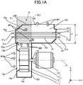
- An air conditioner according to the present embodiment is mounted on a railway vehicle.
- This air conditioner includes a blower device 1 and heat-exchange device 2.
- the blower device 1 includes a centrifugal fan 11, a first casing 13 that houses the centrifugal fan 11, a shaft 14, and a motor 15 that drives the centrifugal fan 11.
- the centrifugal fan 11 sucks in air, as indicated by arrows AR1 of FIG. 1A , from one side in a direction of a rotation axis J1 of the centrifugal fan 11 by rotating the centrifugal fan 11 about the rotation axis J1 and discharges the air, as indicated by arrows AR2 of FIG. 1A , in a direction perpendicular to the rotation axis J1.
- the centrifugal fan 11 is connected to the motor 15 via the shaft 14.
- the direction of the rotation J1 of the centrifugal fan 11 is referred to as the Z-axis direction
- the direction that is perpendicular to the direction in the rotation axis J1 and extends along the arrangement of the blower device 1 and the heat-exchange device 2 one after another is referred to the X-axis direction
- the direction perpendicular to the Z-axis direction and the X-axis direction is referred to as the Y-axis direction.
- the first casing 13 is shaped like a generally flat box and includes main walls 13c and 13d that are of the same shape and mutually oppose each other in the Z-axis direction, and a side wall 13e that encloses the region between the main walls 13c and 13d.
- the centrifugal fan 11 is disposed inside of the first casing 13 such that the rotation axis J1 of the centrifugal fan 11 is along the thickness direction of the first casing 13.
- the main wall 13c of the first casing 13 is provided with an intake opening 13a facing the centrifugal fan 11.
- a portion of the side wall 13e of the first casing 13 is provided with a discharge opening 13b.
- the main wall 13d is provided with a hole 13f enabling the shaft 14 to be inserted therethrough.
- the motor 15 is arranged on one side along the rotation axis J1 with respect to the first casing 13.
- the heat-exchange device 2 includes twelve heater elements 21 that are heat-exchange elements and a second casing 22 that houses the heater elements 21.
- Each heater element 21 includes a heating element such as a resistance wire.
- Each heater element 21 is long and is supplied with electrical power from outside of the second casing 22, via a connection portion 21a at both ends of the heater element 21 in the lengthwise direction thereof.
- the heater element 21 is arranged such that lengthwise direction is parallel with the rotation axis J1 of the centrifugal fan 11. A portion of the heater element 21 is arranged beyond region A1 being the region into which a majority of the air discharged via the discharge opening 13b of the first casing 13 assumedly flows, when the blower device 1 alone is used.
- Region A1 includes the edges of the discharge opening 13b of the first casing 13 in the rotation axis J1 direction (Z-axis direction) of the centrifugal fan 11 and corresponds to an area defined between two virtual planes PL1 and PL2 that are perpendicular to the rotation axis J1 of the centrifugal fan 11. Also, the heater element 21 has a portion extending in the Z-axis direction beyond the centrifugal fan 11 on the motor 15 side.
- the second casing 22 is generally cuboid-shaped and includes main walls 22c and 22d facing each other in the X-axis direction, a pair of side walls 22e facing each other in the Z-axis direction, and a pair of side walls 22h facing each other in the Y-axis direction.
- the main wall 22c that is arranged on the blower device 1 side is provided with an introduction opening 22a for introducing into the interior of the second casing 22 air discharged through the discharge opening 13b by the blower device 1.
- the main wall 22d that is on a side opposite to the side of the blower device 1 is provided with an ejection opening 22b for ejecting air that is introduced into the interior of the second casing 22 and heat-exchanged by the heater element 21.
- the second casing 22 has a portion extending in the Z-axis direction beyond the centrifugal fan 11 on the motor 15 side.
- the introduction opening 22a is provided in the main wall 22c on one end of the second casing 22 in the lengthwise direction of the second casing 22.
- the ejection opening 22b is provided in the main wall 22d on the other end of the second casing 22 in the lengthwise direction of the second casing 22.
- the ejection opening 22b is provided at a position displaced with respect to the introduction opening 22a in the lengthwise direction of the heater element 21, as viewed from the direction perpendicular to the lengthwise direction of the heater element 21. Therefore, the air introduced via the introduction opening 22a, flows along the lengthwise direction of the heater element 21 toward the outside of region A1 as indicated by arrows AR3 of FIG. 1A , and then is ejected via the ejection opening 22b to outside of the second casing 22 as indicated by arrows AR4 of FIG. 1A .
- a slanted portion 22f is provided slanting so as to approach the side of the main wall 22d as distance from the introduction opening 22a increases.
- a slanted portion 22g is provided slanting so as to approach the side of the main wall 22c as distance from the ejection opening 22b increases.
- a portion of the air flowing via the introduction opening 22a directly forward into the interior of the second casing 22 comes into contact with the slanted portion 22g and gets directed toward the ejection opening 22b.
- a portion of the air flowing via the introduction opening 22a into the interior of the second casing 22 and toward an end on the side opposite to the side of the introduction opening 22a comes into contact with the slanted portion 22f and gets directed toward the ejection opening 22b.
- the second casing 22 is provided with the ejection opening 22b at a position displaced in the lengthwise direction of the heater element 21 with respect to the introduction opening 22a and also is provided with the slanted portions 22f and 22g in the main walls 22c and 22d, respectively.
- the air introduced via the introduction opening 22a spreads through the entirety of the interior of the second casing 22, comes in contact with the entirety of each heater element 21, undergoes heat each exchange, and then is ejected from the ejection opening 22b.
- the heater element 21 and the second casing 22 each have a portion extending in the Z-axis direction beyond the centrifugal fan 11 on the motor 15 side.
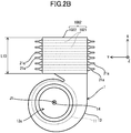
- FIGS. 2A and 2B there are twelve heater elements 1021 that are rod-shaped and arranged entirely within region A10 being a region into which a majority of the air discharged via the discharge opening 13b of the first casing 13 assumedly flows, when the blower device 1 alone is used.
- the twelve heater elements 1021 are arranged such that the lengthwise direction of each heater element 1021 is parallel with the direction perpendicular to the rotation axis J1 of the centrifugal fan 11, two of the heater elements 1021 being arrayed in the rotation axis J1 direction of the centrifugal fan 11 (Z-axis direction), and six of the heater elements 1021 being arrayed in the direction perpendicular to the rotation axis J1 of the centrifugal fan 11 and perpendicular to the lengthwise direction of the heater elements 1021 (X-axis direction).
- Region A10 includes the edges of the discharge opening 13b of the first casing 13 in the rotation axis J1 direction (Z-axis direction) of the centrifugal fan 11 and corresponds to an area defined between two virtual planes PL11 and PL12 that are perpendicular to the rotation axis J1 of the centrifugal fan 11.
- Length L10 in the X-axis direction of the second casing 1022 is set to a length long enough for the second casing 1022 to house the six heater elements 1021 arrayed in the X-axis direction.
- the twelve heater elements 21 are arranged such that the lengthwise direction of each heater element 21 is parallel with the rotation axis J1 of the centrifugal fan 11, six of the heater elements 21 being arrayed in the Y-axis direction, and the heater elements 21 being arrayed in twos in the X-axis direction. Further, length L1 in the X-axis direction of the second casing 22 is set to a length long enough for the second casing 22 to house the two heater elements 21 arrayed in the X-axis direction.
- the length L1 in the X-axis direction of the second casing 22 is shorter compared with the length L10 of the second casing 1022 in the X-axis direction according to the comparative example illustrated in FIGS. 2A and 2B . Therefore, the overall length in the X-axis direction of the air conditioner according to the present disclosure can be made shorter than that of the air conditioner according to the comparative example, because the length of the second casing 22 in the X-axis direction in the present embodiment is less than the length of the second casing 1022 in the X-axis direction in the comparative example. Further, the air conditioner of the present embodiment can be made more compact than the air conditioner according to the comparative example.
- the second casing 22 is configured such that the flow of air introduced into the interior of the second casing via the introduction opening 22a spreads out in the lengthwise direction of the heating element 21. Therefore, in the lengthwise direction of the heater element 21, the length of the heater element 21 portion that is contacted by air introduced via the introduction opening 22a can be extended, and thus heat-exchange efficiency of the heat-exchange device 2 can be improved. In this manner, the heat-exchange efficiency of the heat-exchange device 2 can be improved without increasing the quantity of heater elements 21, and thus an increase in air-path resistance in the heat-exchange device 2 can be prevented and a drop in airflow speed of the air blown out by the air conditioner can be suppressed. Therefore, efficient air conditioning of a target space can be achieved. Also, since the heat-exchange efficiency of the heat-exchange device 2 can be improved without increasing the quantity of heater elements 21, a compact air conditioner with improved heat-exchange efficiency can be achieved.
- the ejection opening 22b is provided at a position displaced with respect to the introduction opening 22a in the lengthwise direction of heater element 21, as viewed from the direction perpendicular to the lengthwise direction of the heater element 21. Therefore, the flow of air introduced inside the second casing 22 via the introduction opening 22a can be directed in the lengthwise direction of the heater element 21 with a relatively simple configuration, thereby simplifying the configuration of the second casing 22.
- the heater element 21 and the second casing 22 each have at least a portion extending in the rotation axis J1 direction beyond the centrifugal fan 11 on the motor 15 side. Therefore, the motor 15, the heater element 21, and the second casing 22 can be tightly arranged in a relatively small space, thereby reducing the overall size of the air conditioner.
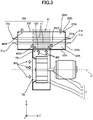
- a heat-exchange device 202 of an air conditioner according to the present embodiment, as illustrated in FIG. 3 , is different from that in Embodiment 1 in that the heat-exchange device 202 includes a second casing 222 provided with an introduction opening 222a in the midsection thereof and a porous member 223 covering the introduction opening 222a of the second casing 222.
- the existence of the porous member 223 causes a portion of air introduced via the introduction opening 222a to flow in a spreading manner in the lengthwise direction of the heater element 21.
- the same components as in Embodiment 1 are given the same references numbers as in FIGS. 1A and 1B .
- the second casing 222 has a flat cuboid-like shape and includes main walls 222c and 222d facing each other in the X-axis direction, a pair of side walls 222e facing each other in the Z-axis direction, and a pair of side walls 222h facing each other in the Y-axis direction.
- the introduction opening 222a is provided in the midsection of the main wall 222c that is arranged on the blower device 1 side.
- an ejection opening 222b is provided in the main wall 222d on the side opposite to the blower device 1 wide.
- the porous member 223 includes a mesh member formed from perforated metal, metal, or a resin.
- the existence of the porous member 223 causes air discharged by the blower device 1 to the introduction opening 222a of the second casing 222 to flow in a spreading manner to beyond region A1, as indicated by arrows AR23 of FIG. 3 .
- This region A1 as described in Embodiment 1, is the region into which a majority of the air discharged via the discharge opening 13b of the first casing 13 assumedly flows, when the blower device 1 alone is used.
- a portion of the air discharged to the introduction opening 222a of the second casing 222 by the blower device 1 flows in a spreading manner in the lengthwise direction of the heater element 21.
- the air flowing in a spreading manner in the lengthwise direction of the heater element 21 undergoes heat exchange across the entire lengthwise direction of the heater element 21 and then is ejected via the ejection opening 222b to the outside of the second casing 222 as indicated by arrows AR24 of FIG 3 .
- the porous member 223 covers the introduction opening 222a of the second casing 222. Therefore, in the lengthwise direction of the heater element 21, the length of the heater element 21 portion that is contacted by air introduced via the introduction opening 222a can be extended, and thus heat-exchange efficiency of the heat-exchange device 202 can be improved, as in Embodiment 1.
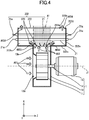
- a heat-exchange device 302 of an air conditioner according to the present embodiment, as illustrated in FIG. 4 is different from that in Embodiment 1 in that the heat-exchange device 302 includes the second casing 222 described in Embodiment 2 and an airflow-directing plate 323 that directs the air flow introduced through the introduction opening 222a of the second casing 222 into the lengthwise direction of the heater element 21.
- the existence of the airflow-directing plate 323 in this heat-exchange device 302 causes a portion of the air introduced via the introduction opening 222a to flow in a spreading manner along lengthwise direction of the heater element 21.
- the same components as in Embodiment 1 and Embodiment 2 are given the same references numbers as in FIGS. 1A , 1B , and FIG. 3 .
- the airflow-directing plate 323 is arranged in close proximity to the introduction opening 222a on the inside of the second casing 222.
- the airflow-directing plate 323 is formed from metal or resin.
- the air discharged by the blower device 1 via the discharge opening 13b to the introduction opening 222a of the second casing 222 flows in a spreading manner beyond region A1 as indicated by arrows AR33 of FIG. 4 .
- a portion of the air discharged by the blower device 1 to the introduction opening 222a of the second casing 222 flows in a spreading manner in the lengthwise direction of the element 21.
- the air flowing in a spreading manner in the lengthwise direction of the heater element 21 undergoes heat exchange across the entire lengthwise direction of the heater element 21 and then is ejected via the ejection opening 222b to the outside of the second casing 222 as indicated by arrows AR34 of FIG 4 .
- the airflow-directing plate 323 redirects the flow of air introduced via the introduction opening 222a of the second casing 222 into the lengthwise direction of the heater element 21. Therefore, as in Embodiment 1, with the present configuration, the length of the heater element 21 portion that is contacted by air introduced via the introduction opening 222a can be extended in the lengthwise direction of the heater element 21, and thus the heat-exchange efficiency of the heat-exchange device 302 can be improved.
- the ejection opening 522b of the second casing 522 may be provided in a location beyond region A1 in the side wall 22h of the second casing 522.
- the air introduced via the introduction opening 22a flows beyond region A1 as indicated by arrows AR3 of FIG. 5A and then is ejected to outside of the second casing 522 via the ejection opening 522b as indicated by arrows AR4 of FIG. 5B .
- the length of the heater element 21 portion that is contacted by air introduced via the introduction opening 22a can be extended in the lengthwise direction of the heater element 21. Therefore, the heat-exchange efficiency of the heat-exchange device 502 can be improved.
- each heat heater element 21 is arranged to be parallel with the rotation axis J1 of the centrifugal fan 11.
- the heater element 21 is not restricted to this arrangement.
- each heater element 421 of a heat-exchange 402 may be arranged parallel with a direction perpendicular to the rotation axis J1 of the centrifugal fan 11.
- an ejection opening 422b of a second casing 422 opposing an introduction opening 422a of the second casing 422 across the heater element 21, preferably is provided at a position displaced with respect to the introduction opening 422a in the lengthwise direction of the heater element 21, as viewed from the direction perpendicular to the lengthwise direction of the heater element 21.
- the second casing 422 has a flat cuboid-like shape and includes main walls 422c and 422d, a pair of side walls 422e facing each other in the Z-axis direction, and a pair of side walls 422h facing each other in the Y-axis direction.
- the second casing 422 arranged such that the lengthwise direction of the second casing 422 is perpendicular to the rotation axis J1 of the centrifugal fan 11.
- the introduction opening 422a is provided in the main wall 422c on one end of the second casing 422 in the lengthwise direction of the second casing 422 and the ejection opening 422b is provided in the main wall 422d on the other end of the second casing 422 in the lengthwise direction of the second casing 422.
- the air introduced via the introduction opening 422a flows in a spreading manner beyond region A4.
- This region A4, as described in Embodiment 1, is the region into which a majority of the air discharged via the discharge opening 13b of the first casing 13 assumedly flows, when the blower device 1 alone is used.
- the air introduced via the introduction opening 422a flows beyond region A4 in the lengthwise direction of the heater element 21 as indicated by arrows AR43 of FIG. 6 and then is ejected to the outside of the second casing 422 via the ejection opening 422b as indicated by arrows AR44 of FIG. 6 .
- a slanted portion 422f is provided slanting so as to approach the side of the side of the main wall 422d as distance from the introduction opening 422a increases.
- a slanted portion 422g is provided slanting so as to approach the side of the main wall 422c as distance from the ejection opening 422b increases.
- the length of the heater element 21 portion that is contacted by air introduced via the introduction opening 422a can be extended. Therefore, heat-exchange efficiency of the heat-exchange device 402 can be improved.
- the introduction opening 22a of the second casing 22 of the heat-exchange device 2 according to aforementioned Embodiment 1 may be covered by the porous member described in Embodiment 2.
- the heat-exchange device 2 may be equipped with the airflow-directing plate described in Embodiment 3, in close proximity to the introduction opening 22a of the second casing 22.
- the heat-exchange device 2 is described as having the heater element 21. However, this is intended to be illustrative and not limiting. Instead of having the heater element 21, the heat-exchange device 2 may have a refrigerant pipe (not illustrated) filled with refrigerant instead. In such a case, the air introduced into the interior of the heat-exchange device 2 by the blower device 1 is cooled by the refrigerant pipe and then is ejected.
- the motor 15 is described as being connected directly to shaft 14. However, this is intended to be illustrative and not limiting.
- the shaft 14 may be connected to the motor 15 via a gear mechanism such as a reduction gear.
- Embodiments and variations according to the present disclosure have been described above, but the present disclosure is not limited to these embodiments and variations.
- the present disclosure includes any appropriate combination of the embodiments and variations, as well as including any appropriate modification thereto.
- the present disclosure is suitably applicable to air conditioners mounted on railway vehicles.
Abstract
Description
- The present disclosure relates to an air conditioner.
- An air conditioner including a blower device having a centrifugal fan, and a heat-exchange device having a heat exchanger element, that heats and cools air discharged from the blower device has been proposed (refer to Patent Literature 1). In an air conditioner of this type, the heat-exchange element of the heat-exchange device typically is disposed in a region into which a majority of air discharged from the blower device flows.
- In the air conditioner of this type, conceivably, the quantity of heat-exchange elements in the region, in which the majority of air discharged from the blower device flows into, is increased or the heat-exchange element is formed into a serpentine shape that meanders within that region, in order to increase the area of contact between the air and the heating element, thereby improving the heat-exchange efficiency of the heat-exchange device.
- Patent Literature 1: Unexamined Japanese Patent Application Kokai Publication No.
2002-180995 - However, in such cases, the air-path resistance in the heat-exchange device may thereby increase causing the airflow speed of the air blown out by the air conditioner to drop, and efficient air conditioning of a target space by the air conditioner may not therefore be achieved. Also, if, in order to improve heat exchange efficiency, the quantity of heat-exchange elements is increased in the region into which the majority of the air discharged by the blower device flows, the air conditioner may need to be increased in size proportionate to the increase in the quantity of heat-exchange elements.
- In consideration of the aforementioned circumstances, an objective of the present disclosure is to provide an air conditioner that provides high heat-exchange efficiency and is compact in size.
- In order to attain the aforementioned objective, an air-conditioner of the present disclosure includes a blower device including:
- a centrifugal fan; and
- a first casing that houses the centrifugal fan, the first casing having an intake opening provided at a location in a direction of a rotation axis of the centrifugal fan at which the intake opening faces the centrifugal fan and having a discharge opening provided at a location in a circumferential wall of the first casing at which the discharge opening faces the centrifugal fan in a direction perpendicular to the rotation axis of the centrifugal fan; and
- a heat-exchange element; and
- a second casing that houses the heat-exchange element, the second casing having an introduction opening for introducing into an interior of the second casing air discharged, via the discharge opening, by the centrifugal fan and having an ejection opening for ejecting, to outside of the second casing, air introduced into the interior of the second casing and heat-exchanged by the heat-exchange element,
- According to the present disclosure, the second casing is configured such that the flow of air introduced into the interior of the second casing via the introduction opening spreads out in the lengthwise direction of the heat-exchange element. Therefore, the length of the portion of the heat-exchange element contacted by air introduced via the introduction opening can be further extended in the lengthwise direction of the heat-exchange element, thereby improving heat-exchange efficiency of the heat-exchange device while preventing an increase in air-path resistance in the heat-exchange device. Thus, efficient air conditioning of a target space can be achieved. Also, since the heat-exchange efficiency of the heat-exchange device can be improved without increasing the quantity of heat-exchange elements, a compact air conditioner with improved heat-exchange efficiency can be achieved.
-
-
FIG. 1A is a cross-sectional view of an air conditioner according toEmbodiment 1 of the present disclosure; -
FIG. 1B is a side elevational view of the air conditioner according toEmbodiment 1; -
FIG. 2A is a cross-sectional view of an air conditioner in a comparative example; -
FIG. 2B is a side elevational view of the air conditioner in the comparative example; -
FIG. 3 is a cross-sectional view of an air conditioner inEmbodiment 2 of the present disclosure; -
FIG. 4 is a cross-sectional view of an air conditioner in Embodiment 3 of the present disclosure; -
FIG. 5A is a cross-sectional view of an air conditioner in a modified example of the present disclosure; -
FIG. 5B is a fragmentary side elevational view taken along line A-A ofFIG. 5A ; and -
FIG. 6 is a fragmentary side elevational view of the air conditioner according to a modified example of the present disclosure. - Embodiments of an air conditioner of the present disclosure are described below in detail with reference to the drawings.
- An air conditioner according to the present embodiment is mounted on a railway vehicle. This air conditioner, as illustrated in
FIGS. 1A and1B , includes ablower device 1 and heat-exchange device 2. Theblower device 1 includes acentrifugal fan 11, afirst casing 13 that houses thecentrifugal fan 11, ashaft 14, and amotor 15 that drives thecentrifugal fan 11. - The
centrifugal fan 11 sucks in air, as indicated by arrows AR1 ofFIG. 1A , from one side in a direction of a rotation axis J1 of thecentrifugal fan 11 by rotating thecentrifugal fan 11 about the rotation axis J1 and discharges the air, as indicated by arrows AR2 ofFIG. 1A , in a direction perpendicular to the rotation axis J1. Thecentrifugal fan 11 is connected to themotor 15 via theshaft 14. Hereinafter, for the sake of convenience, the direction of the rotation J1 of thecentrifugal fan 11 is referred to as the Z-axis direction, the direction that is perpendicular to the direction in the rotation axis J1 and extends along the arrangement of theblower device 1 and the heat-exchange device 2 one after another is referred to the X-axis direction, and the direction perpendicular to the Z-axis direction and the X-axis direction is referred to as the Y-axis direction. - The
first casing 13 is shaped like a generally flat box and includesmain walls side wall 13e that encloses the region between themain walls centrifugal fan 11 is disposed inside of thefirst casing 13 such that the rotation axis J1 of thecentrifugal fan 11 is along the thickness direction of thefirst casing 13. Themain wall 13c of thefirst casing 13 is provided with an intake opening 13a facing thecentrifugal fan 11. Also, a portion of theside wall 13e of thefirst casing 13 is provided with a discharge opening 13b. Themain wall 13d is provided with ahole 13f enabling theshaft 14 to be inserted therethrough. - The
motor 15 is arranged on one side along the rotation axis J1 with respect to thefirst casing 13. - The heat-
exchange device 2, as illustrated inFIG. 1B , includes twelveheater elements 21 that are heat-exchange elements and asecond casing 22 that houses theheater elements 21. Eachheater element 21 includes a heating element such as a resistance wire. Eachheater element 21 is long and is supplied with electrical power from outside of thesecond casing 22, via aconnection portion 21a at both ends of theheater element 21 in the lengthwise direction thereof. Theheater element 21 is arranged such that lengthwise direction is parallel with the rotation axis J1 of thecentrifugal fan 11. A portion of theheater element 21 is arranged beyond region A1 being the region into which a majority of the air discharged via thedischarge opening 13b of thefirst casing 13 assumedly flows, when theblower device 1 alone is used. Region A1 includes the edges of thedischarge opening 13b of thefirst casing 13 in the rotation axis J1 direction (Z-axis direction) of thecentrifugal fan 11 and corresponds to an area defined between two virtual planes PL1 and PL2 that are perpendicular to the rotation axis J1 of thecentrifugal fan 11. Also, theheater element 21 has a portion extending in the Z-axis direction beyond thecentrifugal fan 11 on themotor 15 side. - The
second casing 22 is generally cuboid-shaped and includesmain walls side walls 22e facing each other in the Z-axis direction, and a pair ofside walls 22h facing each other in the Y-axis direction. Of the twomain walls main wall 22c that is arranged on theblower device 1 side is provided with anintroduction opening 22a for introducing into the interior of thesecond casing 22 air discharged through thedischarge opening 13b by theblower device 1. Also, of the twomain walls main wall 22d that is on a side opposite to the side of theblower device 1 is provided with anejection opening 22b for ejecting air that is introduced into the interior of thesecond casing 22 and heat-exchanged by theheater element 21. Also, thesecond casing 22 has a portion extending in the Z-axis direction beyond thecentrifugal fan 11 on themotor 15 side. - The
introduction opening 22a is provided in themain wall 22c on one end of thesecond casing 22 in the lengthwise direction of thesecond casing 22. Theejection opening 22b is provided in themain wall 22d on the other end of thesecond casing 22 in the lengthwise direction of thesecond casing 22. In other words, theejection opening 22b is provided at a position displaced with respect to the introduction opening 22a in the lengthwise direction of theheater element 21, as viewed from the direction perpendicular to the lengthwise direction of theheater element 21. Therefore, the air introduced via theintroduction opening 22a, flows along the lengthwise direction of theheater element 21 toward the outside of region A1 as indicated by arrows AR3 ofFIG. 1A , and then is ejected via the ejection opening 22b to outside of thesecond casing 22 as indicated by arrows AR4 ofFIG. 1A . - In the
main wall 22c, at the end on the side opposite to the side of the introduction opening 22a in the lengthwise direction of themain wall 22c, a slantedportion 22f is provided slanting so as to approach the side of themain wall 22d as distance from the introduction opening 22a increases. Also, in themain wall 22d, at the end on the side opposite to the side of the ejection opening 22b in the lengthwise direction of themain wall 22d, a slantedportion 22g is provided slanting so as to approach the side of themain wall 22c as distance from the ejection opening 22b increases. Thus, a portion of the air flowing via the introduction opening 22a directly forward into the interior of thesecond casing 22 comes into contact with the slantedportion 22g and gets directed toward theejection opening 22b. Also, a portion of the air flowing via the introduction opening 22a into the interior of thesecond casing 22 and toward an end on the side opposite to the side of theintroduction opening 22a, comes into contact with the slantedportion 22f and gets directed toward theejection opening 22b. - In this manner, the
second casing 22 is provided with the ejection opening 22b at a position displaced in the lengthwise direction of theheater element 21 with respect to the introduction opening 22a and also is provided with theslanted portions main walls second casing 22, comes in contact with the entirety of eachheater element 21, undergoes heat each exchange, and then is ejected from theejection opening 22b. - The
heater element 21 and thesecond casing 22 each have a portion extending in the Z-axis direction beyond thecentrifugal fan 11 on themotor 15 side. - Next, the features of the air conditioner according to the present embodiment are described compared with that in a comparison example. In an air conditioner according to the comparison example, as illustrated in
FIGS. 2A and2B , there are twelveheater elements 1021 that are rod-shaped and arranged entirely within region A10 being a region into which a majority of the air discharged via thedischarge opening 13b of thefirst casing 13 assumedly flows, when theblower device 1 alone is used. More specifically, the twelveheater elements 1021 are arranged such that the lengthwise direction of eachheater element 1021 is parallel with the direction perpendicular to the rotation axis J1 of thecentrifugal fan 11, two of theheater elements 1021 being arrayed in the rotation axis J1 direction of the centrifugal fan 11 (Z-axis direction), and six of theheater elements 1021 being arrayed in the direction perpendicular to the rotation axis J1 of thecentrifugal fan 11 and perpendicular to the lengthwise direction of the heater elements 1021 (X-axis direction). Region A10 includes the edges of thedischarge opening 13b of thefirst casing 13 in the rotation axis J1 direction (Z-axis direction) of thecentrifugal fan 11 and corresponds to an area defined between two virtual planes PL11 and PL12 that are perpendicular to the rotation axis J1 of thecentrifugal fan 11. - Length L10 in the X-axis direction of the
second casing 1022 is set to a length long enough for thesecond casing 1022 to house the sixheater elements 1021 arrayed in the X-axis direction. - Conversely, in the air conditioner according to the present embodiment, as illustrated in
FIGS. 1A and1B , the twelveheater elements 21 are arranged such that the lengthwise direction of eachheater element 21 is parallel with the rotation axis J1 of thecentrifugal fan 11, six of theheater elements 21 being arrayed in the Y-axis direction, and theheater elements 21 being arrayed in twos in the X-axis direction. Further, length L1 in the X-axis direction of thesecond casing 22 is set to a length long enough for thesecond casing 22 to house the twoheater elements 21 arrayed in the X-axis direction. In other words, the length L1 in the X-axis direction of thesecond casing 22 is shorter compared with the length L10 of thesecond casing 1022 in the X-axis direction according to the comparative example illustrated inFIGS. 2A and2B . Therefore, the overall length in the X-axis direction of the air conditioner according to the present disclosure can be made shorter than that of the air conditioner according to the comparative example, because the length of thesecond casing 22 in the X-axis direction in the present embodiment is less than the length of thesecond casing 1022 in the X-axis direction in the comparative example. Further, the air conditioner of the present embodiment can be made more compact than the air conditioner according to the comparative example. - As described above, in the air conditioner according to the present embodiment, the
second casing 22 is configured such that the flow of air introduced into the interior of the second casing via the introduction opening 22a spreads out in the lengthwise direction of theheating element 21. Therefore, in the lengthwise direction of theheater element 21, the length of theheater element 21 portion that is contacted by air introduced via theintroduction opening 22a can be extended, and thus heat-exchange efficiency of the heat-exchange device 2 can be improved. In this manner, the heat-exchange efficiency of the heat-exchange device 2 can be improved without increasing the quantity ofheater elements 21, and thus an increase in air-path resistance in the heat-exchange device 2 can be prevented and a drop in airflow speed of the air blown out by the air conditioner can be suppressed. Therefore, efficient air conditioning of a target space can be achieved. Also, since the heat-exchange efficiency of the heat-exchange device 2 can be improved without increasing the quantity ofheater elements 21, a compact air conditioner with improved heat-exchange efficiency can be achieved. - Also, in the air conditioner according to the present embodiment, the
ejection opening 22b is provided at a position displaced with respect to the introduction opening 22a in the lengthwise direction ofheater element 21, as viewed from the direction perpendicular to the lengthwise direction of theheater element 21. Therefore, the flow of air introduced inside thesecond casing 22 via theintroduction opening 22a can be directed in the lengthwise direction of theheater element 21 with a relatively simple configuration, thereby simplifying the configuration of thesecond casing 22. - Furthermore, in the air conditioner according to the present embodiment, the
heater element 21 and thesecond casing 22 each have at least a portion extending in the rotation axis J1 direction beyond thecentrifugal fan 11 on themotor 15 side. Therefore, themotor 15, theheater element 21, and thesecond casing 22 can be tightly arranged in a relatively small space, thereby reducing the overall size of the air conditioner. - A heat-
exchange device 202 of an air conditioner according to the present embodiment, as illustrated inFIG. 3 , is different from that inEmbodiment 1 in that the heat-exchange device 202 includes asecond casing 222 provided with anintroduction opening 222a in the midsection thereof and aporous member 223 covering the introduction opening 222a of thesecond casing 222. In this heat-exchange device 202, the existence of theporous member 223 causes a portion of air introduced via theintroduction opening 222a to flow in a spreading manner in the lengthwise direction of theheater element 21. InFIG. 3 , the same components as inEmbodiment 1 are given the same references numbers as inFIGS. 1A and1B . - The
second casing 222 has a flat cuboid-like shape and includesmain walls side walls 222e facing each other in the Z-axis direction, and a pair ofside walls 222h facing each other in the Y-axis direction. Theintroduction opening 222a is provided in the midsection of themain wall 222c that is arranged on theblower device 1 side. Also, anejection opening 222b is provided in themain wall 222d on the side opposite to theblower device 1 wide. - The
porous member 223 includes a mesh member formed from perforated metal, metal, or a resin. - The existence of the
porous member 223 causes air discharged by theblower device 1 to the introduction opening 222a of thesecond casing 222 to flow in a spreading manner to beyond region A1, as indicated by arrows AR23 ofFIG. 3 . This region A1, as described inEmbodiment 1, is the region into which a majority of the air discharged via thedischarge opening 13b of thefirst casing 13 assumedly flows, when theblower device 1 alone is used. Here, a portion of the air discharged to the introduction opening 222a of thesecond casing 222 by theblower device 1 flows in a spreading manner in the lengthwise direction of theheater element 21. The air flowing in a spreading manner in the lengthwise direction of theheater element 21 undergoes heat exchange across the entire lengthwise direction of theheater element 21 and then is ejected via the ejection opening 222b to the outside of thesecond casing 222 as indicated by arrows AR24 ofFIG 3 . - In the air conditioner according to the present embodiment, the
porous member 223 covers the introduction opening 222a of thesecond casing 222. Therefore, in the lengthwise direction of theheater element 21, the length of theheater element 21 portion that is contacted by air introduced via theintroduction opening 222a can be extended, and thus heat-exchange efficiency of the heat-exchange device 202 can be improved, as inEmbodiment 1. - A heat-
exchange device 302 of an air conditioner according to the present embodiment, as illustrated inFIG. 4 , is different from that inEmbodiment 1 in that the heat-exchange device 302 includes thesecond casing 222 described inEmbodiment 2 and an airflow-directingplate 323 that directs the air flow introduced through the introduction opening 222a of thesecond casing 222 into the lengthwise direction of theheater element 21. The existence of the airflow-directingplate 323 in this heat-exchange device 302 causes a portion of the air introduced via theintroduction opening 222a to flow in a spreading manner along lengthwise direction of theheater element 21. InFIG. 4 , the same components as inEmbodiment 1 andEmbodiment 2 are given the same references numbers as inFIGS. 1A ,1B , andFIG. 3 . - The airflow-directing
plate 323 is arranged in close proximity to theintroduction opening 222a on the inside of thesecond casing 222. The airflow-directingplate 323 is formed from metal or resin. - Because of the existence of airflow-directing
plate 323, the air discharged by theblower device 1 via thedischarge opening 13b to the introduction opening 222a of thesecond casing 222 flows in a spreading manner beyond region A1 as indicated by arrows AR33 ofFIG. 4 . Here, a portion of the air discharged by theblower device 1 to the introduction opening 222a of thesecond casing 222 flows in a spreading manner in the lengthwise direction of theelement 21. The air flowing in a spreading manner in the lengthwise direction of theheater element 21 undergoes heat exchange across the entire lengthwise direction of theheater element 21 and then is ejected via the ejection opening 222b to the outside of thesecond casing 222 as indicated by arrows AR34 ofFIG 4 . - In the air conditioner according to the present embodiment, the airflow-directing
plate 323 redirects the flow of air introduced via the introduction opening 222a of thesecond casing 222 into the lengthwise direction of theheater element 21. Therefore, as inEmbodiment 1, with the present configuration, the length of theheater element 21 portion that is contacted by air introduced via theintroduction opening 222a can be extended in the lengthwise direction of theheater element 21, and thus the heat-exchange efficiency of the heat-exchange device 302 can be improved. - Embodiments of the present disclosure are described above. However, the present disclosure is not restricted to those embodiments. As illustrated in
FIGS. 5A and5B , in the heat-exchange device 502, the ejection opening 522b of thesecond casing 522 may be provided in a location beyond region A1 in theside wall 22h of thesecond casing 522. In such a case, the air introduced via theintroduction opening 22a, flows beyond region A1 as indicated by arrows AR3 ofFIG. 5A and then is ejected to outside of thesecond casing 522 via the ejection opening 522b as indicated by arrows AR4 ofFIG. 5B . - As in
Embodiment 1, with the present configuration, the length of theheater element 21 portion that is contacted by air introduced via theintroduction opening 22a can be extended in the lengthwise direction of theheater element 21. Therefore, the heat-exchange efficiency of the heat-exchange device 502 can be improved. - Also, in the Embodiments described above, each
heat heater element 21 is arranged to be parallel with the rotation axis J1 of thecentrifugal fan 11. However, theheater element 21 is not restricted to this arrangement. As illustrated inFIG. 6 , eachheater element 421 of a heat-exchange 402 may be arranged parallel with a direction perpendicular to the rotation axis J1 of thecentrifugal fan 11. In such a case, anejection opening 422b of asecond casing 422 opposing anintroduction opening 422a of thesecond casing 422 across theheater element 21, preferably is provided at a position displaced with respect to theintroduction opening 422a in the lengthwise direction of theheater element 21, as viewed from the direction perpendicular to the lengthwise direction of theheater element 21. - In a manner similar with that of
Embodiment 1, thesecond casing 422 has a flat cuboid-like shape and includesmain walls side walls 422e facing each other in the Z-axis direction, and a pair ofside walls 422h facing each other in the Y-axis direction. Thesecond casing 422 arranged such that the lengthwise direction of thesecond casing 422 is perpendicular to the rotation axis J1 of thecentrifugal fan 11. Theintroduction opening 422a is provided in themain wall 422c on one end of thesecond casing 422 in the lengthwise direction of thesecond casing 422 and theejection opening 422b is provided in themain wall 422d on the other end of thesecond casing 422 in the lengthwise direction of thesecond casing 422. Thus, the air introduced via theintroduction opening 422a flows in a spreading manner beyond region A4. This region A4, as described inEmbodiment 1, is the region into which a majority of the air discharged via thedischarge opening 13b of thefirst casing 13 assumedly flows, when theblower device 1 alone is used. - Therefore, the air introduced via the
introduction opening 422a, flows beyond region A4 in the lengthwise direction of theheater element 21 as indicated by arrows AR43 ofFIG. 6 and then is ejected to the outside of thesecond casing 422 via the ejection opening 422b as indicated by arrows AR44 ofFIG. 6 . - Further, in the
main wall 422c, at the end opposite to the side of theintroduction opening 422a in the lengthwise direction of themain wall 422c, a slantedportion 422f is provided slanting so as to approach the side of the side of themain wall 422d as distance from theintroduction opening 422a increases. Also, in themain wall 422d, at the end on the side opposite to the side of the ejection opening 422b in the lengthwise direction of themain wall 422d, a slantedportion 422g is provided slanting so as to approach the side of themain wall 422c as distance from the ejection opening 422b increases. Therefore, in a manner similar to that ofEmbodiment 1, a portion of the air flowing via theintroduction opening 422a directly forward into the interior of thesecond casing 422 comes into contact with the slantedportion 422g and gets directed toward theejection opening 422b. Also a portion of the air flowing via the introduction opening 422a into the interior of thesecond casing 422 toward an end on the side opposite to the side of theintroduction opening 422a, comes into contact with the slantedportion 422f and gets directed toward theejection opening 422b. - With the current configuration, in the lengthwise direction of the
heater element 21, the length of theheater element 21 portion that is contacted by air introduced via theintroduction opening 422a can be extended. Therefore, heat-exchange efficiency of the heat-exchange device 402 can be improved. - The
introduction opening 22a of thesecond casing 22 of the heat-exchange device 2 according toaforementioned Embodiment 1 may be covered by the porous member described inEmbodiment 2. The heat-exchange device 2 may be equipped with the airflow-directing plate described in Embodiment 3, in close proximity to the introduction opening 22a of thesecond casing 22. - In the aforementioned embodiments, the heat-
exchange device 2 is described as having theheater element 21. However, this is intended to be illustrative and not limiting. Instead of having theheater element 21, the heat-exchange device 2 may have a refrigerant pipe (not illustrated) filled with refrigerant instead. In such a case, the air introduced into the interior of the heat-exchange device 2 by theblower device 1 is cooled by the refrigerant pipe and then is ejected. - In the
blower device 1 according to the aforementioned embodiments, themotor 15 is described as being connected directly toshaft 14. However, this is intended to be illustrative and not limiting. Theshaft 14 may be connected to themotor 15 via a gear mechanism such as a reduction gear. - Embodiments and variations according to the present disclosure have been described above, but the present disclosure is not limited to these embodiments and variations. The present disclosure includes any appropriate combination of the embodiments and variations, as well as including any appropriate modification thereto.
- This application claims the benefit of Japanese Patent Application No.
2015-228983, filed on November 24, 2015 - The present disclosure is suitably applicable to air conditioners mounted on railway vehicles.
-
- 1 Blower device
- 2, 202, 302, 402, 502 Heat-exchange device
- 11 Centrifugal fan
- 13 First casing
- 13a Intake opening
- 13b Discharge opening
- 13c, 13d, 22c, 22d, 222c, 222d, 422c, 422d Main wall
- 13e, 22e, 22h, 222e, 222h, 422e, 422h Side wall
- 13f Hole
- 14 Shaft
- 15 Motor
- 21, 421 Heater element
- 21a Connection portion
- 22, 222, 322, 422, 522, Second casing
- 22a, 222a, 422a Introduction opening
- 22b, 222b, 422b, 522b Ejection opening
- 22f, 22g, 422f, 422g Slanted portion
- 223 Porous member
- 323 Airflow-directing plate
- A1, A4 region
- J1 Rotation axis
Claims (5)
- An air conditioner comprising:a blower device comprising:a centrifugal fan; anda first casing that houses the centrifugal fan, the first casing having an intake opening provided at a location in a direction of a rotation axis of the centrifugal fan at which the intake opening faces the centrifugal fan and having a discharge opening provided at a location in a circumferential wall of the first casing at which the discharge opening faces the centrifugal fan in a direction perpendicular to the rotation axis of the centrifugal fan; anda heat-exchange device comprising:a heat-exchange element; anda second casing that houses the heat-exchange element, the second casing having an introduction opening for introducing into an interior of the second casing air discharged, via the discharge opening, by the centrifugal fan and having an ejection opening for ejecting, to outside of the second casing, air introduced into the interior of the second casing and heat-exchanged by the heat-exchange element,wherein the second casing is configured such that a flow of air introduced into the interior of the second casing via the introduction opening spreads out in a lengthwise direction of the heat-exchange element.
- The air conditioner according to claim 1, wherein the ejection opening is provided at a location displaced with respect to the introduction opening in the lengthwise direction of the heat-exchange element, as viewed from a direction perpendicular to the lengthwise direction of the heat-exchange element.
- The air conditioner according to claim 1 or 2, wherein
the blower device further comprises a motor that drives the centrifugal fan, the motor arranged on one side of the first casing, along the rotation axis, and
the heat-exchange element and the second casing each have at least a portion extending in the direction of the rotation axis beyond the centrifugal fan on a side of the motor. - The air conditioner according to any one of claims 1 to 3, wherein the heat-exchange device further comprises a porous member that covers the introduction opening of the second casing.
- The air conditioner according to any one of claims 1 to 4, wherein the heat-exchange device further comprises an airflow-directing plate that directs a flow of air introduced via the introduction opening of the second casing into the lengthwise direction of the heat-exchange element.
Applications Claiming Priority (2)
| Application Number | Priority Date | Filing Date | Title |
|---|---|---|---|
| JP2015228983 | 2015-11-24 | ||
| PCT/JP2016/084773 WO2017090671A1 (en) | 2015-11-24 | 2016-11-24 | Air conditioner |
Publications (3)
| Publication Number | Publication Date |
|---|---|
| EP3382289A1 true EP3382289A1 (en) | 2018-10-03 |
| EP3382289A4 EP3382289A4 (en) | 2019-03-20 |
| EP3382289B1 EP3382289B1 (en) | 2022-05-18 |
Family
ID=58764148
Family Applications (1)
| Application Number | Title | Priority Date | Filing Date |
|---|---|---|---|
| EP16868614.5A Active EP3382289B1 (en) | 2015-11-24 | 2016-11-24 | Air conditioner |
Country Status (6)
| Country | Link |
|---|---|
| US (1) | US20180328384A1 (en) |
| EP (1) | EP3382289B1 (en) |
| JP (1) | JP6433606B2 (en) |
| CN (1) | CN108291726A (en) |
| HK (1) | HK1254932A1 (en) |
| WO (1) | WO2017090671A1 (en) |
Family Cites Families (34)
| Publication number | Priority date | Publication date | Assignee | Title |
|---|---|---|---|---|
| US1938801A (en) * | 1931-07-21 | 1933-12-12 | Maxim Silencer Co | Ventilating and air conditioning device |
| US2468909A (en) * | 1946-01-03 | 1949-05-03 | Cnossen | Auxiliary air heater |
| US2768814A (en) * | 1950-10-27 | 1956-10-30 | Frey | Plate warmer exchanger |
| US3306070A (en) * | 1965-10-24 | 1967-02-28 | Carrier Corp | Air conditioning unit |
| CA958214A (en) * | 1972-04-26 | 1974-11-26 | Conat Industries Limited | Humidifying unit |
| US4031862A (en) * | 1976-03-10 | 1977-06-28 | Smith Frank J | Economizer |
| US4090370A (en) * | 1976-03-11 | 1978-05-23 | Vaughan Kenneth F | Environmental control system |
| US4167210A (en) * | 1977-11-23 | 1979-09-11 | Westinghouse Electric Corp. | Electric heat module mounting arrangement for roof top type air conditioning unit |
| JPS5837416U (en) * | 1981-09-04 | 1983-03-11 | 松下冷機株式会社 | air conditioner |
| JPS5949111U (en) * | 1982-09-20 | 1984-04-02 | 松下電器産業株式会社 | air conditioner |
| JPH0264824U (en) * | 1988-11-01 | 1990-05-16 | ||
| JPH10220858A (en) * | 1997-02-06 | 1998-08-21 | Fujitsu General Ltd | Air conditioner |
| CN2298152Y (en) * | 1997-07-16 | 1998-11-25 | 北京弘大汽车空调散热器有限公司 | Jeep air conditioner |
| US5944090A (en) * | 1998-01-30 | 1999-08-31 | Teal; William J. | Heat exchanger for furnace flue |
| KR20000056578A (en) * | 1999-02-24 | 2000-09-15 | 구자홍 | Air-conditioner |
| JP2005003278A (en) * | 2003-06-12 | 2005-01-06 | Fujitsu General Ltd | Air conditioner |
| JP2006145109A (en) * | 2004-11-19 | 2006-06-08 | Matsushita Electric Ind Co Ltd | Air conditioner |
| CN1815091A (en) * | 2005-02-04 | 2006-08-09 | 松下电器产业株式会社 | Air conditioner |
| KR20070031715A (en) * | 2005-09-15 | 2007-03-20 | 삼성전자주식회사 | Ventilation unit for air conditioner |
| KR20070060501A (en) * | 2005-12-08 | 2007-06-13 | 삼성전자주식회사 | Air conditioner |
| KR20070069533A (en) * | 2005-12-28 | 2007-07-03 | 엘지전자 주식회사 | Indoor unit of air conditioner |
| JP3979434B2 (en) * | 2006-01-04 | 2007-09-19 | ダイキン工業株式会社 | Air conditioner |
| KR20090124562A (en) * | 2008-05-30 | 2009-12-03 | 삼성전자주식회사 | Air conditioner |
| CN101896054A (en) * | 2009-05-21 | 2010-11-24 | 富准精密工业(深圳)有限公司 | Radiating device |
| US20110005719A1 (en) * | 2009-07-10 | 2011-01-13 | Keihin Corporation | Heat exchanger for vehicular air conditioning apparatus |
| JP5062265B2 (en) * | 2010-02-15 | 2012-10-31 | ダイキン工業株式会社 | Air conditioner |
| KR101492144B1 (en) * | 2010-09-06 | 2015-02-10 | 한라비스테온공조 주식회사 | Air conditioner for vehicle |
| EP2565550B1 (en) * | 2011-09-01 | 2018-10-10 | LG Electronics Inc. | Ventilation apparatus |
| CN202328530U (en) * | 2011-11-11 | 2012-07-11 | 天加空调(天津)有限公司 | Sheet metal part corner combination construction of fan chassis and fan-coil unit thereof |
| CN202432613U (en) * | 2012-01-16 | 2012-09-12 | 珠海格力电器股份有限公司 | Internal machine of air-conditioner and air-conditioner comprising same |
| KR101340271B1 (en) * | 2013-06-19 | 2013-12-10 | 김광수 | The energy-saving smart safety apparatus for blowing cold and warm air with applying four seasons |
| CN104566625B (en) * | 2013-10-09 | 2018-04-17 | 珠海格力电器股份有限公司 | Air pipe indoor machine |
| JP2015199488A (en) * | 2014-04-01 | 2015-11-12 | 株式会社デンソー | Air conditioner for vehicle |
| CN204026843U (en) * | 2014-06-25 | 2014-12-17 | 美的集团股份有限公司 | Wall-hanging air conditioner indoor unit |
-
2016
- 2016-11-24 EP EP16868614.5A patent/EP3382289B1/en active Active
- 2016-11-24 WO PCT/JP2016/084773 patent/WO2017090671A1/en active Application Filing
- 2016-11-24 JP JP2017552689A patent/JP6433606B2/en active Active
- 2016-11-24 CN CN201680065420.5A patent/CN108291726A/en active Pending
- 2016-11-24 US US15/776,036 patent/US20180328384A1/en not_active Abandoned
-
2018
- 2018-11-02 HK HK18114034.9A patent/HK1254932A1/en unknown
Also Published As
| Publication number | Publication date |
|---|---|
| EP3382289A4 (en) | 2019-03-20 |
| HK1254932A1 (en) | 2019-08-02 |
| JP6433606B2 (en) | 2018-12-05 |
| US20180328384A1 (en) | 2018-11-15 |
| EP3382289B1 (en) | 2022-05-18 |
| JPWO2017090671A1 (en) | 2018-03-29 |
| CN108291726A (en) | 2018-07-17 |
| WO2017090671A1 (en) | 2017-06-01 |
Similar Documents
| Publication | Publication Date | Title |
|---|---|---|
| JP2007241991A (en) | Low profile liquid cooled server heat sink | |
| US20080205001A1 (en) | Blower and air conditioner for vehicle | |
| EP2719970A2 (en) | Indoor unit of air conditioner | |
| JP6559799B2 (en) | Cooling unit for cooling the air received inside the switch cabinet and corresponding switchgear cabinet assembly | |
| JP2008309121A (en) | Fan shroud structure | |
| ITBO20120499A1 (en) | VENTILATION UNIT. | |
| CN113167540A (en) | Heat exchanger module for a motor vehicle | |
| US9618216B2 (en) | Air conditioning apparatus | |
| JP2019092371A (en) | Electric motor including exchanger and multiple cooling circuits | |
| EP3382289B1 (en) | Air conditioner | |
| DK177870B1 (en) | A cooling unit for a climatized cabinet | |
| JP2007234792A (en) | Electronic apparatus cooling device | |
| JP2010158948A (en) | Vehicle air conditioning unit | |
| US11255335B2 (en) | Blower assembly for use in an air handling system and method for assembling the same | |
| JP6382788B2 (en) | Cooling system | |
| US20070114003A1 (en) | Modular heating system for large vehicles | |
| JP6170548B2 (en) | Heat exchanger tube, heat exchanger tube bundle, heat exchanger with heat exchanger tube bundle, and method of manufacturing plate of heat exchanger tube | |
| EP2719961B1 (en) | Indoor unit of air conditioner | |
| US20060285293A1 (en) | Information processing apparatus with a chassis for thermal efficiency and method for making the same | |
| CN113574258A (en) | Cooling module with sacrificial region for electric vehicle | |
| JP6382787B2 (en) | Cooling system | |
| JP2014101036A (en) | Vehicle air conditioner | |
| CN207132435U (en) | Air conditioner | |
| JP2007248044A (en) | Integrally printed blower speed resistor circuit on evaporator | |
| JP2008117876A (en) | Cold air circulating system |
Legal Events
| Date | Code | Title | Description |
|---|---|---|---|
| STAA | Information on the status of an ep patent application or granted ep patent |
Free format text: STATUS: THE INTERNATIONAL PUBLICATION HAS BEEN MADE |
|
| PUAI | Public reference made under article 153(3) epc to a published international application that has entered the european phase |
Free format text: ORIGINAL CODE: 0009012 |
|
| STAA | Information on the status of an ep patent application or granted ep patent |
Free format text: STATUS: REQUEST FOR EXAMINATION WAS MADE |
|
| 17P | Request for examination filed |
Effective date: 20180322 |
|
| AK | Designated contracting states |
Kind code of ref document: A1 Designated state(s): AL AT BE BG CH CY CZ DE DK EE ES FI FR GB GR HR HU IE IS IT LI LT LU LV MC MK MT NL NO PL PT RO RS SE SI SK SM TR |
|
| AX | Request for extension of the european patent |
Extension state: BA ME |
|
| DAV | Request for validation of the european patent (deleted) | ||
| DAX | Request for extension of the european patent (deleted) | ||
| A4 | Supplementary search report drawn up and despatched |
Effective date: 20190220 |
|
| RIC1 | Information provided on ipc code assigned before grant |
Ipc: F24F 1/00 20190101ALN20190213BHEP Ipc: B60H 1/00 20060101ALI20190213BHEP Ipc: F24F 13/30 20060101ALI20190213BHEP Ipc: F24F 13/20 20060101AFI20190213BHEP Ipc: F04D 29/44 20060101ALN20190213BHEP |
|
| STAA | Information on the status of an ep patent application or granted ep patent |
Free format text: STATUS: EXAMINATION IS IN PROGRESS |
|
| 17Q | First examination report despatched |
Effective date: 20200326 |
|
| STAA | Information on the status of an ep patent application or granted ep patent |
Free format text: STATUS: EXAMINATION IS IN PROGRESS |
|
| GRAJ | Information related to disapproval of communication of intention to grant by the applicant or resumption of examination proceedings by the epo deleted |
Free format text: ORIGINAL CODE: EPIDOSDIGR1 |
|
| GRAP | Despatch of communication of intention to grant a patent |
Free format text: ORIGINAL CODE: EPIDOSNIGR1 |
|
| REG | Reference to a national code |
Ref country code: DE Ref legal event code: R079 Ref document number: 602016072318 Country of ref document: DE Free format text: PREVIOUS MAIN CLASS: F24F0001000000 Ipc: F24F0013200000 |
|
| RIC1 | Information provided on ipc code assigned before grant |
Ipc: F24F 1/0022 20190101ALN20211011BHEP Ipc: F04D 29/44 20060101ALN20211011BHEP Ipc: F24F 1/0011 20190101ALN20211011BHEP Ipc: B60H 1/00 20060101ALI20211011BHEP Ipc: F24F 13/30 20060101ALI20211011BHEP Ipc: F24F 13/20 20060101AFI20211011BHEP |
|
| RIC1 | Information provided on ipc code assigned before grant |
Ipc: F24F 1/0022 20190101ALN20211020BHEP Ipc: F04D 29/44 20060101ALN20211020BHEP Ipc: F24F 1/0011 20190101ALN20211020BHEP Ipc: B60H 1/00 20060101ALI20211020BHEP Ipc: F24F 13/30 20060101ALI20211020BHEP Ipc: F24F 13/20 20060101AFI20211020BHEP |
|
| GRAP | Despatch of communication of intention to grant a patent |
Free format text: ORIGINAL CODE: EPIDOSNIGR1 |
|
| STAA | Information on the status of an ep patent application or granted ep patent |
Free format text: STATUS: GRANT OF PATENT IS INTENDED |
|
| RIC1 | Information provided on ipc code assigned before grant |
Ipc: F24F 1/0022 20190101ALN20211108BHEP Ipc: F04D 29/44 20060101ALN20211108BHEP Ipc: F24F 1/0011 20190101ALN20211108BHEP Ipc: B60H 1/00 20060101ALI20211108BHEP Ipc: F24F 13/30 20060101ALI20211108BHEP Ipc: F24F 13/20 20060101AFI20211108BHEP |
|
| RIC1 | Information provided on ipc code assigned before grant |
Ipc: F24F 1/0022 20190101ALN20211115BHEP Ipc: F04D 29/44 20060101ALN20211115BHEP Ipc: F24F 1/0011 20190101ALN20211115BHEP Ipc: B60H 1/00 20060101ALI20211115BHEP Ipc: F24F 13/30 20060101ALI20211115BHEP Ipc: F24F 13/20 20060101AFI20211115BHEP |
|
| INTG | Intention to grant announced |
Effective date: 20211206 |
|
| GRAJ | Information related to disapproval of communication of intention to grant by the applicant or resumption of examination proceedings by the epo deleted |
Free format text: ORIGINAL CODE: EPIDOSDIGR1 |
|
| GRAS | Grant fee paid |
Free format text: ORIGINAL CODE: EPIDOSNIGR3 |
|
| GRAA | (expected) grant |
Free format text: ORIGINAL CODE: 0009210 |
|
| STAA | Information on the status of an ep patent application or granted ep patent |
Free format text: STATUS: THE PATENT HAS BEEN GRANTED |
|
| INTG | Intention to grant announced |
Effective date: 20211206 |
|
| AK | Designated contracting states |
Kind code of ref document: B1 Designated state(s): AL AT BE BG CH CY CZ DE DK EE ES FI FR GB GR HR HU IE IS IT LI LT LU LV MC MK MT NL NO PL PT RO RS SE SI SK SM TR |
|
| REG | Reference to a national code |
Ref country code: GB Ref legal event code: FG4D |
|
| REG | Reference to a national code |
Ref country code: CH Ref legal event code: EP |
|
| REG | Reference to a national code |
Ref country code: IE Ref legal event code: FG4D |
|
| REG | Reference to a national code |
Ref country code: DE Ref legal event code: R096 Ref document number: 602016072318 Country of ref document: DE |
|
| REG | Reference to a national code |
Ref country code: AT Ref legal event code: REF Ref document number: 1493363 Country of ref document: AT Kind code of ref document: T Effective date: 20220615 |
|
| REG | Reference to a national code |
Ref country code: LT Ref legal event code: MG9D |
|
| REG | Reference to a national code |
Ref country code: NL Ref legal event code: MP Effective date: 20220518 |
|
| REG | Reference to a national code |
Ref country code: AT Ref legal event code: MK05 Ref document number: 1493363 Country of ref document: AT Kind code of ref document: T Effective date: 20220518 |
|
| PG25 | Lapsed in a contracting state [announced via postgrant information from national office to epo] |
Ref country code: SE Free format text: LAPSE BECAUSE OF FAILURE TO SUBMIT A TRANSLATION OF THE DESCRIPTION OR TO PAY THE FEE WITHIN THE PRESCRIBED TIME-LIMIT Effective date: 20220518 Ref country code: PT Free format text: LAPSE BECAUSE OF FAILURE TO SUBMIT A TRANSLATION OF THE DESCRIPTION OR TO PAY THE FEE WITHIN THE PRESCRIBED TIME-LIMIT Effective date: 20220919 Ref country code: NO Free format text: LAPSE BECAUSE OF FAILURE TO SUBMIT A TRANSLATION OF THE DESCRIPTION OR TO PAY THE FEE WITHIN THE PRESCRIBED TIME-LIMIT Effective date: 20220818 Ref country code: NL Free format text: LAPSE BECAUSE OF FAILURE TO SUBMIT A TRANSLATION OF THE DESCRIPTION OR TO PAY THE FEE WITHIN THE PRESCRIBED TIME-LIMIT Effective date: 20220518 Ref country code: LT Free format text: LAPSE BECAUSE OF FAILURE TO SUBMIT A TRANSLATION OF THE DESCRIPTION OR TO PAY THE FEE WITHIN THE PRESCRIBED TIME-LIMIT Effective date: 20220518 Ref country code: HR Free format text: LAPSE BECAUSE OF FAILURE TO SUBMIT A TRANSLATION OF THE DESCRIPTION OR TO PAY THE FEE WITHIN THE PRESCRIBED TIME-LIMIT Effective date: 20220518 Ref country code: GR Free format text: LAPSE BECAUSE OF FAILURE TO SUBMIT A TRANSLATION OF THE DESCRIPTION OR TO PAY THE FEE WITHIN THE PRESCRIBED TIME-LIMIT Effective date: 20220819 Ref country code: FI Free format text: LAPSE BECAUSE OF FAILURE TO SUBMIT A TRANSLATION OF THE DESCRIPTION OR TO PAY THE FEE WITHIN THE PRESCRIBED TIME-LIMIT Effective date: 20220518 Ref country code: ES Free format text: LAPSE BECAUSE OF FAILURE TO SUBMIT A TRANSLATION OF THE DESCRIPTION OR TO PAY THE FEE WITHIN THE PRESCRIBED TIME-LIMIT Effective date: 20220518 Ref country code: BG Free format text: LAPSE BECAUSE OF FAILURE TO SUBMIT A TRANSLATION OF THE DESCRIPTION OR TO PAY THE FEE WITHIN THE PRESCRIBED TIME-LIMIT Effective date: 20220818 Ref country code: AT Free format text: LAPSE BECAUSE OF FAILURE TO SUBMIT A TRANSLATION OF THE DESCRIPTION OR TO PAY THE FEE WITHIN THE PRESCRIBED TIME-LIMIT Effective date: 20220518 |
|
| PG25 | Lapsed in a contracting state [announced via postgrant information from national office to epo] |
Ref country code: RS Free format text: LAPSE BECAUSE OF FAILURE TO SUBMIT A TRANSLATION OF THE DESCRIPTION OR TO PAY THE FEE WITHIN THE PRESCRIBED TIME-LIMIT Effective date: 20220518 Ref country code: PL Free format text: LAPSE BECAUSE OF FAILURE TO SUBMIT A TRANSLATION OF THE DESCRIPTION OR TO PAY THE FEE WITHIN THE PRESCRIBED TIME-LIMIT Effective date: 20220518 Ref country code: LV Free format text: LAPSE BECAUSE OF FAILURE TO SUBMIT A TRANSLATION OF THE DESCRIPTION OR TO PAY THE FEE WITHIN THE PRESCRIBED TIME-LIMIT Effective date: 20220518 Ref country code: IS Free format text: LAPSE BECAUSE OF FAILURE TO SUBMIT A TRANSLATION OF THE DESCRIPTION OR TO PAY THE FEE WITHIN THE PRESCRIBED TIME-LIMIT Effective date: 20220918 |
|
| PG25 | Lapsed in a contracting state [announced via postgrant information from national office to epo] |
Ref country code: SM Free format text: LAPSE BECAUSE OF FAILURE TO SUBMIT A TRANSLATION OF THE DESCRIPTION OR TO PAY THE FEE WITHIN THE PRESCRIBED TIME-LIMIT Effective date: 20220518 Ref country code: SK Free format text: LAPSE BECAUSE OF FAILURE TO SUBMIT A TRANSLATION OF THE DESCRIPTION OR TO PAY THE FEE WITHIN THE PRESCRIBED TIME-LIMIT Effective date: 20220518 Ref country code: RO Free format text: LAPSE BECAUSE OF FAILURE TO SUBMIT A TRANSLATION OF THE DESCRIPTION OR TO PAY THE FEE WITHIN THE PRESCRIBED TIME-LIMIT Effective date: 20220518 Ref country code: EE Free format text: LAPSE BECAUSE OF FAILURE TO SUBMIT A TRANSLATION OF THE DESCRIPTION OR TO PAY THE FEE WITHIN THE PRESCRIBED TIME-LIMIT Effective date: 20220518 Ref country code: DK Free format text: LAPSE BECAUSE OF FAILURE TO SUBMIT A TRANSLATION OF THE DESCRIPTION OR TO PAY THE FEE WITHIN THE PRESCRIBED TIME-LIMIT Effective date: 20220518 Ref country code: CZ Free format text: LAPSE BECAUSE OF FAILURE TO SUBMIT A TRANSLATION OF THE DESCRIPTION OR TO PAY THE FEE WITHIN THE PRESCRIBED TIME-LIMIT Effective date: 20220518 |
|
| REG | Reference to a national code |
Ref country code: DE Ref legal event code: R097 Ref document number: 602016072318 Country of ref document: DE |
|
| PLBE | No opposition filed within time limit |
Free format text: ORIGINAL CODE: 0009261 |
|
| STAA | Information on the status of an ep patent application or granted ep patent |
Free format text: STATUS: NO OPPOSITION FILED WITHIN TIME LIMIT |
|
| PG25 | Lapsed in a contracting state [announced via postgrant information from national office to epo] |
Ref country code: AL Free format text: LAPSE BECAUSE OF FAILURE TO SUBMIT A TRANSLATION OF THE DESCRIPTION OR TO PAY THE FEE WITHIN THE PRESCRIBED TIME-LIMIT Effective date: 20220518 |
|
| 26N | No opposition filed |
Effective date: 20230221 |
|
| PG25 | Lapsed in a contracting state [announced via postgrant information from national office to epo] |
Ref country code: SI Free format text: LAPSE BECAUSE OF FAILURE TO SUBMIT A TRANSLATION OF THE DESCRIPTION OR TO PAY THE FEE WITHIN THE PRESCRIBED TIME-LIMIT Effective date: 20220518 |
|
| P01 | Opt-out of the competence of the unified patent court (upc) registered |
Effective date: 20230512 |
|
| PG25 | Lapsed in a contracting state [announced via postgrant information from national office to epo] |
Ref country code: MC Free format text: LAPSE BECAUSE OF FAILURE TO SUBMIT A TRANSLATION OF THE DESCRIPTION OR TO PAY THE FEE WITHIN THE PRESCRIBED TIME-LIMIT Effective date: 20220518 |
|
| REG | Reference to a national code |
Ref country code: CH Ref legal event code: PL |
|
| REG | Reference to a national code |
Ref country code: BE Ref legal event code: MM Effective date: 20221130 |
|
| PG25 | Lapsed in a contracting state [announced via postgrant information from national office to epo] |
Ref country code: LI Free format text: LAPSE BECAUSE OF NON-PAYMENT OF DUE FEES Effective date: 20221130 Ref country code: CH Free format text: LAPSE BECAUSE OF NON-PAYMENT OF DUE FEES Effective date: 20221130 |
|
| PG25 | Lapsed in a contracting state [announced via postgrant information from national office to epo] |
Ref country code: LU Free format text: LAPSE BECAUSE OF NON-PAYMENT OF DUE FEES Effective date: 20221124 |
|
| PG25 | Lapsed in a contracting state [announced via postgrant information from national office to epo] |
Ref country code: IE Free format text: LAPSE BECAUSE OF NON-PAYMENT OF DUE FEES Effective date: 20221124 |
|
| PG25 | Lapsed in a contracting state [announced via postgrant information from national office to epo] |
Ref country code: BE Free format text: LAPSE BECAUSE OF NON-PAYMENT OF DUE FEES Effective date: 20221130 |
|
| PGFP | Annual fee paid to national office [announced via postgrant information from national office to epo] |
Ref country code: FR Payment date: 20230929 Year of fee payment: 8 |
|
| PGFP | Annual fee paid to national office [announced via postgrant information from national office to epo] |
Ref country code: GB Payment date: 20231006 Year of fee payment: 8 |
|
| PGFP | Annual fee paid to national office [announced via postgrant information from national office to epo] |
Ref country code: IT Payment date: 20231010 Year of fee payment: 8 Ref country code: DE Payment date: 20230929 Year of fee payment: 8 |
|
| PG25 | Lapsed in a contracting state [announced via postgrant information from national office to epo] |
Ref country code: HU Free format text: LAPSE BECAUSE OF FAILURE TO SUBMIT A TRANSLATION OF THE DESCRIPTION OR TO PAY THE FEE WITHIN THE PRESCRIBED TIME-LIMIT; INVALID AB INITIO Effective date: 20161124 |