EP3379127B1 - Muffenverbindung - Google Patents
Muffenverbindung Download PDFInfo
- Publication number
- EP3379127B1 EP3379127B1 EP18162009.7A EP18162009A EP3379127B1 EP 3379127 B1 EP3379127 B1 EP 3379127B1 EP 18162009 A EP18162009 A EP 18162009A EP 3379127 B1 EP3379127 B1 EP 3379127B1
- Authority
- EP
- European Patent Office
- Prior art keywords
- ring
- bayonet
- socket
- tip end
- joint according
- Prior art date
- Legal status (The legal status is an assumption and is not a legal conclusion. Google has not performed a legal analysis and makes no representation as to the accuracy of the status listed.)
- Active
Links
Images


Classifications
-
- F—MECHANICAL ENGINEERING; LIGHTING; HEATING; WEAPONS; BLASTING
- F16—ENGINEERING ELEMENTS AND UNITS; GENERAL MEASURES FOR PRODUCING AND MAINTAINING EFFECTIVE FUNCTIONING OF MACHINES OR INSTALLATIONS; THERMAL INSULATION IN GENERAL
- F16L—PIPES; JOINTS OR FITTINGS FOR PIPES; SUPPORTS FOR PIPES, CABLES OR PROTECTIVE TUBING; MEANS FOR THERMAL INSULATION IN GENERAL
- F16L37/00—Couplings of the quick-acting type
- F16L37/08—Couplings of the quick-acting type in which the connection between abutting or axially overlapping ends is maintained by locking members
- F16L37/10—Couplings of the quick-acting type in which the connection between abutting or axially overlapping ends is maintained by locking members using a rotary external sleeve or ring on one part
- F16L37/113—Couplings of the quick-acting type in which the connection between abutting or axially overlapping ends is maintained by locking members using a rotary external sleeve or ring on one part the male part having lugs on its periphery penetrating into the corresponding slots provided in the female part
-
- F—MECHANICAL ENGINEERING; LIGHTING; HEATING; WEAPONS; BLASTING
- F16—ENGINEERING ELEMENTS AND UNITS; GENERAL MEASURES FOR PRODUCING AND MAINTAINING EFFECTIVE FUNCTIONING OF MACHINES OR INSTALLATIONS; THERMAL INSULATION IN GENERAL
- F16L—PIPES; JOINTS OR FITTINGS FOR PIPES; SUPPORTS FOR PIPES, CABLES OR PROTECTIVE TUBING; MEANS FOR THERMAL INSULATION IN GENERAL
- F16L37/00—Couplings of the quick-acting type
- F16L37/008—Couplings of the quick-acting type for branching pipes; for joining pipes to walls
Definitions
- the invention relates to a socket connection between a socket body and a spigot end of a piece of pipe, which in particular are each made of cast iron, in particular cast metal.
- socket connections are known from the prior art, for example from WO 2015/159228 A1 , DE 20313792 U1 and US 2008/0258463 A1 .
- the advantage of the solution according to the invention is that it makes it possible to easily secure the spigot end against moving out of the sleeve body with the bayonet ring, but also to easily release the bayonet ring in order to release the sleeve connection to be able to
- the piece of pipe is held in place with high tensile strength and, in particular, there is the possibility of using the piece of pipe in a steplessly rotated manner and, for example, also rotating it.
- the bayonet ring can be inserted with its bayonet bodies into the bayonet receptacle of the sleeve body in a release position and can be moved in the bayonet receptacle into a holding position by rotating it in the bayonet receptacle about a central axis of the sleeve body, in which the bayonet ring with its bayonet bodies counter a movement parallel to the central axis of the bayonet mount and in particular also of the socket body is fixed.
- connection between the bayonet ring with the bayonet bodies and the bayonet receptacle in the socket body can be established in a simple manner.
- the bayonet mount of the sleeve body is arranged between an insertion opening of the sleeve body and the sealing seat or the at least one sealing ring on the sleeve body, so that starting from the insertion opening, the sealing seat or the at least one sealing ring sit deeper in the sleeve body than the bayonet mount.
- the sealing seat or the at least one sealing ring is located between the bayonet mount and a connecting opening leading from a base element carrying the sleeve body in the sleeve body.
- the medium to be conducted through the socket connection flows through the connection opening either from the base element via the connection opening into the socket body and in this into the spigot end of the pipe section, or the medium to be supplied exits from the spigot end of the pipe section into the socket body and exits from the socket body into the base member via the connection opening.
- a particularly advantageous solution provides that the sealing seat and the sealing ring are arranged coaxially to a central axis of the sleeve body, so that there is the possibility of rotating the spigot end about the central axis relative to the sleeve body.
- the sealing seat is designed as a surface that is cylindrical with respect to the central axis of the sleeve body, against which the at least one sealing ring rests and causes a seal between the sealing seat and the spigot end by radial pressure.
- Such a design of the sealing seat has the great advantage that the position of the spigot end relative to the socket body is insensitive to slight displacements in the direction of the central axis of the socket body with regard to the sealing effect.
- a solution has proven particularly favorable in which the sealing seat is arranged in the sleeve body and the at least one sealing ring is arranged on the spigot end.
- the sealing ring is held in a sealing ring receptacle on the spigot end and is thus fixed relative to it.
- bayonet ring is arranged on a side of the sealing seat or of the at least one sealing ring on the spigot end that faces away from an end face of the spigot end.
- This solution has the advantage that the fixing of the spigot end relative to the sleeve body is arranged outside of the area sealed by the sealing seat or the at least one sealing ring for guiding the medium through the sleeve connection.
- the spigot end is supported on the bayonet ring with at least one supporting body.
- the bayonet ring is preferably arranged on a side of the support body facing away from the sealing seat or the at least one sealing ring, so that the support body can easily secure the spigot end against moving out of the socket body by being supported on the bayonet ring.
- a particularly advantageous embodiment provides that the spigot end carries a retaining ring as a supporting body, with which it is supported on the bayonet ring.
- the retaining ring can be fixed to the spigot end in a wide variety of ways.
- the retaining ring prefferably be connected to the spigot end in one piece or with a material bond.
- a particularly favorable solution provides that the retaining ring is held in a form-fitting manner in a holding receptacle on the spigot end.
- Another advantageous solution provides for the retaining ring to have a form-fitting connection at one point on the circumference, which can be released for radial expansion of the retaining ring.
- the widened retaining ring can thus preferably be inserted into the retaining receptacle of the spigot end and, after the positive connection has been made, fixed in the retaining receptacle against movement in the direction of the central axis relative to the spigot end.
- the bayonet ring encloses the spigot end with a ring body and can thus be arranged on the spigot end in a simple manner.
- annular body can be rotated relative to the spigot end.
- the bayonet ring is designed in such a way that the annular body of the bayonet ring carries a flange body of the bayonet ring, with which the bayonet ring can preferably be rotated.
- the ring body and the flange body are connected to one another in one piece.
- the flange body of the bayonet ring is arranged outside the sleeve body in the direction of the central axis, so that the flange body can be acted on in a simple manner.
- the flange body is preferably arranged in such a way that it covers the insertion opening of the sleeve body.
- the flange body is arranged overlapping an end face of the sleeve body that encloses the insertion opening.
- the bayonet ring in the socket body can be blocked or blocked in a rotationally fixed manner by a blocking body.
- the blocking body is expediently guided on the bayonet ring so that it can move parallel to the central axis, in order to be able to move it between a blocking position and a release position.
- the blocking body engages in a recess in the socket body to fix the bayonet ring in a rotationally fixed manner.
- Such a recess in the sleeve body could be a recess provided exclusively for accommodating the blocking body.
- a particularly simple solution provides that such a recess is an insertion receptacle for the bayonet bodies provided in the bayonet receptacle.
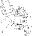
- a in 1 illustrated embodiment of a sleeve connection according to the invention comprises a sleeve body 12, in which a piece of pipe 14 is inserted with a spigot end 16.
- the sleeve body 12 is formed onto a base element 18, it being possible for the base element 18 to be designed in a wide variety of ways.
- the base element 18 can be a piece of pipe. However, the base element 18 can also be part of a fitting housing or part of a shaped piece.
- the base element 18 is, for example, part of a fitting housing, in particular part of a cover of a fitting housing.
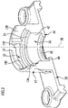
- the sleeve body 12 comprises, as in 2 shown in detail, an insertion opening 22 through which the spigot end 16 of the pipe section 14 can be inserted into an interior space 24 enclosed by the sleeve body 12 .
- the insertion opening 22 is followed by a bayonet mount, designated as a whole by 32, which is used to hold an in 1 illustrated bayonet ring 34 is used, as described in detail below.
- a bayonet mount designated as a whole by 32, which is used to hold an in 1 illustrated bayonet ring 34 is used, as described in detail below.
- sealing seat 36 On the side of bayonet receptacle 32 opposite insertion opening 22, there is a sealing seat 36, which preferably has a sealing surface 42 running cylindrically to a central axis 38 of sleeve body 12, which extends between bayonet receptacle 32 and a stop body 44, which, for example, has a bearing on the base element 18 leading connection opening 46 encloses, through which a medium can enter from the base member 18 in an inner 48 of the pipe section 14 or vice versa.
- Sealing between the spigot end 16 of the pipe section 14 and the sealing seat 36 with the sealing surface 42 is preferably carried out, as shown in FIG 1 shown, by ring sealing elements 52 and 54, which are inserted into these receiving grooves 56 and 58 on an outer peripheral side of the spigot end 16 and, when the spigot end 16 engages in the socket body 12, protrude radially in the direction of the sealing surface 42 to such an extent that the sealing rings 52 and 54 are tight on the one hand finally sit in the receiving grooves 56 and 58 and on the other hand tightly, in particular with pressure in the radial direction to the central axis 38, on the sealing surface 42 of the sealing seat 36 of the sleeve body 12 abut.
- an end face 62 of the spigot end 16 of the pipe section 14 preferably rests against a flange surface 64 formed by the stop body 44, so that the depth of insertion of the spigot end in the insertion direction 66 in the socket body 12 is limited.
- the spigot end 16 is secured against moving out of the socket body 12 in the opposite direction to the insertion direction 66 by the interaction of the bayonet ring 34 with the bayonet receptacle 32 of the socket body 12.
- a holding receptacle 72 e.g. designed as a holding groove, is provided, in which a retaining ring 74 is received between two retaining surfaces 76, 78 secured against displacement in the direction of a central axis 82 of the spigot end 16.
- the retaining ring 74 is held immovably on the spigot end 16 in the direction of the central axis 82 .
- the retaining ring 74 comprises, as in 4 shown, two ring halves 84 and 86, which are connected on the one hand by a joint 88, for example a hinge, in particular a film hinge, and on the other hand, the joint 88 opposite by a latching connection 92 are connected to each other.
- a joint 88 for example a hinge, in particular a film hinge
- the snap-in connection 92 includes snap-in hooks 94, 96 which can be moved radially towards one another and engage in one another and with which a positive connection can be produced between the ring halves 84 and 86 in the area of the snap-in connection 92.
- the spigot end 16 is supported by the retaining ring 74 on the bayonet ring 34, which encloses the spigot end 16 on a side of the retaining ring 74 that faces away from the sealing rings 52 and 54, so that the retaining ring 74 has a retaining ring surface 102 that faces away from the sealing rings 52 and 54 is, can be supported on a support ring surface 104 of the bayonet ring 34.
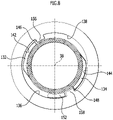
- the bayonet ring 34 which can be brought into engagement with the bayonet mount 32 comprises, as shown in FIGS figure 5 , 6 , 7 and 8th shown, an annular body 112, which encloses the spigot end 16 on an outer peripheral side 114 and is guided with an inner surface 116 on the outer peripheral side 114.
- the ring body 112 carries the support ring surface 104 on one side, on which the retaining ring 74 with the retaining ring surface 102 is supported.
- the ring body 112 is provided on a side facing away from the support ring surface 104 with a flange body 122, which protrudes radially to the center axis 82 of the spigot end 16 beyond the ring body 112 and, for example, when the bayonet ring 34 is inserted into the bayonet receptacle 32, as shown in FIG 1 shown, the socket body 12 at its end face 124 facing away from the base element 18 engages over.
- bayonet bodies 132 and 134 are located on annular body 112 in a direction parallel to central axis 82 at a distance from annular flange 122, which in a direction parallel to central axis 38 have insertion receptacles 136 and 138 that are open toward insertion opening 22 and are therefore accessible from the side of insertion opening 22 of the bayonet receptacle 32 and, starting from these insertion receptacles 136 and 138, can be moved into holding receptacles 142 and 144 by rotating about the central axis 38, in which the bayonet bodies 132 and 134 are fixed against movement in the direction of the central axis 38 and thus also the bayonet ring 34 fix against a movement in the direction of the central axis 38 in the bayonet mount 32.
- the holding mounts As in 2 shown, provided with end faces 146 and 148 against which the bayonet bodies 132 and 134 can be placed in the fixing position.
- the flange body 122 of the bayonet ring 32 is also provided with a safety slide 152, which is guided in a slide guide 154 penetrating the flange body 122 so that it can be displaced in a direction parallel to the central axis 38 relative to the flange body 122, so that the safety slide 152 can be moved in the fixing position of the bayonet ring 34, shown in FIG the 7 and 8th , can be inserted into one of the insertion receptacles 136, 138, for example the insertion receptacle 136, and can thereby block a rotational movement of the bayonet ring 34 when the
- safety slide 152 To secure safety slide 152, which engages in insertion receptacles 136, in this position, safety slide 152 is provided with a latching element 162, which interacts with a latching element 164 assigned to the slide guide when safety slide 152, in its position blocking the rotational movement of bayonet ring 34, moves into the insertion receptacle 136 retracted position is available.
- the spigot end 16 of the pipe section 14 is produced in such a way that it already has the receiving grooves 56 and 58 for the sealing rings 52 and 54 and the retaining receptacle 72 for the retaining ring 74 .
- the bayonet ring 34 is first pushed onto a spigot end 16 prepared in this way, parallel to the central axis 82, until the inner surface 116 of the annular body 112 of the bayonet ring 34 encompasses the outer peripheral side 114 of the spigot end 116 and is thus guided in a rotatable manner on it.
- the retaining ring 74 is then inserted into the retaining receptacle 62 of the spigot end 16 , the retaining ring 74 already bearing with its retaining ring surface 102 against the support ring surface 104 of the annular body 112 .
- the sealing rings 52 and 54 are mounted by inserting them into the receiving grooves 56 and 58.
- the securing slide 152 is also displaced far enough relative to the flange body 122 that it does not protrude beyond the flange body 122 of the bayonet ring 34 in the direction of the socket body 12, but is merely guided by the slide guide 154 without over the flange body 122 in the direction of the socket body 12 and to survive the bayonet mount 32.
- bayonet ring 34 can be rotated relative to bayonet receptacle 32 in such a way that, starting from insertion opening 22 of sleeve body 12, bayonet bodies 132 and 134 can enter insertion receptacles 136 and 138, to the extent that - as shown in 1 shown, the insertion of the spigot end 16 in the insertion direction 66 is limited by the counter-movement of the end face 62 of the spigot end 16 against the flange face 64 .
- the bayonet ring 34 can be rotated relative to the spigot end 16 in such a way that the bayonet bodies 132 and 134 can enter the holding receptacles 142 and 144 and in these parallel against movement be secured to the central axis 38.
- the securing body 152 is also in a position in which it can be displaced relative to the slide guide 154 in the flange body 122 so far that it can, for example, move into the Insertion receptacle 136 penetrates and in this case rests against the projection 158 and thus prevents the bayonet ring 34 from being rotated from the fixing position into the release position.
- the spigot end 16 of the pipe section 14 in the socket body 12 is thus secured against moving out of the socket body 12 .
- the pipe section 14 can still be twisted relative to the socket body 12, with the sealing rings 52 and 54 still sealingly abutting the sealing surface 42 of the sealing seat 36 and also producing a medium-tight connection between the spigot end 16 and the socket body 12 during a rotary movement .
Landscapes
- Engineering & Computer Science (AREA)
- General Engineering & Computer Science (AREA)
- Mechanical Engineering (AREA)
- Quick-Acting Or Multi-Walled Pipe Joints (AREA)
- Mechanical Coupling Of Light Guides (AREA)
- Connections Effected By Soldering, Adhesion, Or Permanent Deformation (AREA)
Applications Claiming Priority (1)
| Application Number | Priority Date | Filing Date | Title |
|---|---|---|---|
| DE102017106041.3A DE102017106041A1 (de) | 2017-03-21 | 2017-03-21 | Muffenverbindung |
Publications (2)
| Publication Number | Publication Date |
|---|---|
| EP3379127A1 EP3379127A1 (de) | 2018-09-26 |
| EP3379127B1 true EP3379127B1 (de) | 2022-05-11 |
Family
ID=61683665
Family Applications (1)
| Application Number | Title | Priority Date | Filing Date |
|---|---|---|---|
| EP18162009.7A Active EP3379127B1 (de) | 2017-03-21 | 2018-03-15 | Muffenverbindung |
Country Status (6)
| Country | Link |
|---|---|
| EP (1) | EP3379127B1 (pl) |
| DE (1) | DE102017106041A1 (pl) |
| DK (1) | DK3379127T3 (pl) |
| ES (1) | ES2921901T3 (pl) |
| HU (1) | HUE059982T2 (pl) |
| PL (1) | PL3379127T3 (pl) |
Citations (3)
| Publication number | Priority date | Publication date | Assignee | Title |
|---|---|---|---|---|
| DE20313792U1 (de) * | 2003-09-05 | 2003-11-06 | Reinert-Ritz GmbH, 48531 Nordhorn | Zugfeste Rohrverbindung |
| US20080258463A1 (en) * | 2005-01-19 | 2008-10-23 | Tokyo Metropolitan Government | Pipe Joint Construction |
| WO2015159228A1 (en) * | 2014-04-15 | 2015-10-22 | Eaton Corporation | Feedback bulkhead connector assembly |
Family Cites Families (3)
| Publication number | Priority date | Publication date | Assignee | Title |
|---|---|---|---|---|
| FR1372566A (fr) * | 1963-08-01 | 1964-09-18 | Thomson Houston Comp Francaise | Joint intérieur rapide entre éléments à assembler |
| DE20207642U1 (de) * | 2002-05-14 | 2002-09-12 | WP Maschinenbau Widera & Pinske GmbH, 50226 Frechen | Hochdruckfester Verbindungsverschluss |
| DE102010013159A1 (de) * | 2010-03-27 | 2011-09-29 | Vag-Armaturen Gmbh | Steckverbindung |
-
2017
- 2017-03-21 DE DE102017106041.3A patent/DE102017106041A1/de not_active Ceased
-
2018
- 2018-03-15 ES ES18162009T patent/ES2921901T3/es active Active
- 2018-03-15 EP EP18162009.7A patent/EP3379127B1/de active Active
- 2018-03-15 PL PL18162009.7T patent/PL3379127T3/pl unknown
- 2018-03-15 DK DK18162009.7T patent/DK3379127T3/da active
- 2018-03-15 HU HUE18162009A patent/HUE059982T2/hu unknown
Patent Citations (3)
| Publication number | Priority date | Publication date | Assignee | Title |
|---|---|---|---|---|
| DE20313792U1 (de) * | 2003-09-05 | 2003-11-06 | Reinert-Ritz GmbH, 48531 Nordhorn | Zugfeste Rohrverbindung |
| US20080258463A1 (en) * | 2005-01-19 | 2008-10-23 | Tokyo Metropolitan Government | Pipe Joint Construction |
| WO2015159228A1 (en) * | 2014-04-15 | 2015-10-22 | Eaton Corporation | Feedback bulkhead connector assembly |
Also Published As
| Publication number | Publication date |
|---|---|
| PL3379127T3 (pl) | 2022-08-01 |
| ES2921901T3 (es) | 2022-09-02 |
| EP3379127A1 (de) | 2018-09-26 |
| HUE059982T2 (hu) | 2023-01-28 |
| DK3379127T3 (da) | 2022-07-25 |
| DE102017106041A1 (de) | 2018-09-27 |
Similar Documents
| Publication | Publication Date | Title |
|---|---|---|
| DE2938927A1 (de) | Befestigungsvorrichtung fuer teleskopstossdaempfer in aufhaengungen | |
| DE10051805A1 (de) | WC-Sitzgelenk | |
| EP3812329A1 (de) | Schlauchtrommeleinheit und schlauchtrommelanordnung umfassend eine schlauchtrommeleinheit | |
| DE202007012400U1 (de) | Anschlussvorrichtung für Medienleitungen im Bereich einer Wandungsdurchführung sowie Wandungselement | |
| EP2841831B1 (de) | Absperrventil | |
| DE102017222232A1 (de) | Schwingungsdämpfer mit verstellbarer Dämpfkraft | |
| DE202008005929U1 (de) | Anschlussvorrichtung für Medienleitungen im Bereich einer Wandungsdurchführung sowie Wandungselement | |
| DE3126170A1 (de) | Ventilanordnung | |
| DE2225742A1 (de) | Mischventil fuer stroemungsmittel | |
| EP3239575B1 (de) | Käfigventilbaugruppe mit drosselringen | |
| DE2404149A1 (de) | Vorrichtung zum pruefen von rohren, anschlusstuecken und dergl. | |
| DE4030884C2 (de) | Bügellagerung für Farbroller und dergleichen | |
| EP3379127A1 (de) | Muffenverbindung | |
| DE3612495A1 (de) | Drucklager/dichtungs-anordnung | |
| DE7217008U (de) | Absperrhahn mit ueber stangen gegen dichtungssitz pressbarem kuekenteil | |
| DE2951623A1 (de) | Kugelventil | |
| DE102005005789B4 (de) | Druckbehälter in einem Schwingungsdämpfer | |
| DE102009049943A1 (de) | Brühvorrichtung zum Extrahieren einer Portionskapsel | |
| WO2017017093A1 (de) | Gelenkanordnung und rotationsdämpfer | |
| DE4408624A1 (de) | Elektromaschine | |
| DE102020130284A1 (de) | Anschlussbaugruppe für einen Wasserfilter | |
| AT522181A4 (de) | Dichtungsanordnung | |
| DE2357018A1 (de) | Vorrichtung zum abdichten von armaturteilen mittels eines faltenbalges | |
| EP3372887B1 (de) | Anschlussstück | |
| DE102004014581B3 (de) | Blockierungseinrichtung für ein Dichtungselement einer Anordnung zum Einführen wenigstens eines Kabels oder eines Leitungsrohres in ein Gebäude |
Legal Events
| Date | Code | Title | Description |
|---|---|---|---|
| PUAI | Public reference made under article 153(3) epc to a published international application that has entered the european phase |
Free format text: ORIGINAL CODE: 0009012 |
|
| STAA | Information on the status of an ep patent application or granted ep patent |
Free format text: STATUS: THE APPLICATION HAS BEEN PUBLISHED |
|
| AK | Designated contracting states |
Kind code of ref document: A1 Designated state(s): AL AT BE BG CH CY CZ DE DK EE ES FI FR GB GR HR HU IE IS IT LI LT LU LV MC MK MT NL NO PL PT RO RS SE SI SK SM TR |
|
| AX | Request for extension of the european patent |
Extension state: BA ME |
|
| STAA | Information on the status of an ep patent application or granted ep patent |
Free format text: STATUS: REQUEST FOR EXAMINATION WAS MADE |
|
| 17P | Request for examination filed |
Effective date: 20190319 |
|
| RBV | Designated contracting states (corrected) |
Designated state(s): AL AT BE BG CH CY CZ DE DK EE ES FI FR GB GR HR HU IE IS IT LI LT LU LV MC MK MT NL NO PL PT RO RS SE SI SK SM TR |
|
| STAA | Information on the status of an ep patent application or granted ep patent |
Free format text: STATUS: EXAMINATION IS IN PROGRESS |
|
| 17Q | First examination report despatched |
Effective date: 20190626 |
|
| GRAP | Despatch of communication of intention to grant a patent |
Free format text: ORIGINAL CODE: EPIDOSNIGR1 |
|
| STAA | Information on the status of an ep patent application or granted ep patent |
Free format text: STATUS: GRANT OF PATENT IS INTENDED |
|
| INTG | Intention to grant announced |
Effective date: 20211210 |
|
| GRAS | Grant fee paid |
Free format text: ORIGINAL CODE: EPIDOSNIGR3 |
|
| GRAA | (expected) grant |
Free format text: ORIGINAL CODE: 0009210 |
|
| STAA | Information on the status of an ep patent application or granted ep patent |
Free format text: STATUS: THE PATENT HAS BEEN GRANTED |
|
| AK | Designated contracting states |
Kind code of ref document: B1 Designated state(s): AL AT BE BG CH CY CZ DE DK EE ES FI FR GB GR HR HU IE IS IT LI LT LU LV MC MK MT NL NO PL PT RO RS SE SI SK SM TR |
|
| REG | Reference to a national code |
Ref country code: GB Ref legal event code: FG4D Free format text: NOT ENGLISH |
|
| REG | Reference to a national code |
Ref country code: CH Ref legal event code: EP |
|
| REG | Reference to a national code |
Ref country code: AT Ref legal event code: REF Ref document number: 1491674 Country of ref document: AT Kind code of ref document: T Effective date: 20220515 |
|
| REG | Reference to a national code |
Ref country code: DE Ref legal event code: R096 Ref document number: 502018009612 Country of ref document: DE |
|
| REG | Reference to a national code |
Ref country code: IE Ref legal event code: FG4D Free format text: LANGUAGE OF EP DOCUMENT: GERMAN |
|
| REG | Reference to a national code |
Ref country code: NL Ref legal event code: FP |
|
| REG | Reference to a national code |
Ref country code: DK Ref legal event code: T3 Effective date: 20220719 |
|
| REG | Reference to a national code |
Ref country code: SE Ref legal event code: TRGR |
|
| REG | Reference to a national code |
Ref country code: FI Ref legal event code: FGE |
|
| REG | Reference to a national code |
Ref country code: NO Ref legal event code: T2 Effective date: 20220511 |
|
| REG | Reference to a national code |
Ref country code: ES Ref legal event code: FG2A Ref document number: 2921901 Country of ref document: ES Kind code of ref document: T3 Effective date: 20220902 |
|
| REG | Reference to a national code |
Ref country code: LT Ref legal event code: MG9D |
|
| PG25 | Lapsed in a contracting state [announced via postgrant information from national office to epo] |
Ref country code: PT Free format text: LAPSE BECAUSE OF FAILURE TO SUBMIT A TRANSLATION OF THE DESCRIPTION OR TO PAY THE FEE WITHIN THE PRESCRIBED TIME-LIMIT Effective date: 20220912 Ref country code: LT Free format text: LAPSE BECAUSE OF FAILURE TO SUBMIT A TRANSLATION OF THE DESCRIPTION OR TO PAY THE FEE WITHIN THE PRESCRIBED TIME-LIMIT Effective date: 20220511 Ref country code: HR Free format text: LAPSE BECAUSE OF FAILURE TO SUBMIT A TRANSLATION OF THE DESCRIPTION OR TO PAY THE FEE WITHIN THE PRESCRIBED TIME-LIMIT Effective date: 20220511 Ref country code: GR Free format text: LAPSE BECAUSE OF FAILURE TO SUBMIT A TRANSLATION OF THE DESCRIPTION OR TO PAY THE FEE WITHIN THE PRESCRIBED TIME-LIMIT Effective date: 20220812 Ref country code: BG Free format text: LAPSE BECAUSE OF FAILURE TO SUBMIT A TRANSLATION OF THE DESCRIPTION OR TO PAY THE FEE WITHIN THE PRESCRIBED TIME-LIMIT Effective date: 20220811 |
|
| PG25 | Lapsed in a contracting state [announced via postgrant information from national office to epo] |
Ref country code: RS Free format text: LAPSE BECAUSE OF FAILURE TO SUBMIT A TRANSLATION OF THE DESCRIPTION OR TO PAY THE FEE WITHIN THE PRESCRIBED TIME-LIMIT Effective date: 20220511 Ref country code: LV Free format text: LAPSE BECAUSE OF FAILURE TO SUBMIT A TRANSLATION OF THE DESCRIPTION OR TO PAY THE FEE WITHIN THE PRESCRIBED TIME-LIMIT Effective date: 20220511 Ref country code: IS Free format text: LAPSE BECAUSE OF FAILURE TO SUBMIT A TRANSLATION OF THE DESCRIPTION OR TO PAY THE FEE WITHIN THE PRESCRIBED TIME-LIMIT Effective date: 20220911 |
|
| REG | Reference to a national code |
Ref country code: HU Ref legal event code: AG4A Ref document number: E059982 Country of ref document: HU |
|
| PG25 | Lapsed in a contracting state [announced via postgrant information from national office to epo] |
Ref country code: SM Free format text: LAPSE BECAUSE OF FAILURE TO SUBMIT A TRANSLATION OF THE DESCRIPTION OR TO PAY THE FEE WITHIN THE PRESCRIBED TIME-LIMIT Effective date: 20220511 Ref country code: SK Free format text: LAPSE BECAUSE OF FAILURE TO SUBMIT A TRANSLATION OF THE DESCRIPTION OR TO PAY THE FEE WITHIN THE PRESCRIBED TIME-LIMIT Effective date: 20220511 Ref country code: RO Free format text: LAPSE BECAUSE OF FAILURE TO SUBMIT A TRANSLATION OF THE DESCRIPTION OR TO PAY THE FEE WITHIN THE PRESCRIBED TIME-LIMIT Effective date: 20220511 Ref country code: EE Free format text: LAPSE BECAUSE OF FAILURE TO SUBMIT A TRANSLATION OF THE DESCRIPTION OR TO PAY THE FEE WITHIN THE PRESCRIBED TIME-LIMIT Effective date: 20220511 |
|
| REG | Reference to a national code |
Ref country code: DE Ref legal event code: R097 Ref document number: 502018009612 Country of ref document: DE |
|
| PLBE | No opposition filed within time limit |
Free format text: ORIGINAL CODE: 0009261 |
|
| STAA | Information on the status of an ep patent application or granted ep patent |
Free format text: STATUS: NO OPPOSITION FILED WITHIN TIME LIMIT |
|
| PG25 | Lapsed in a contracting state [announced via postgrant information from national office to epo] |
Ref country code: AL Free format text: LAPSE BECAUSE OF FAILURE TO SUBMIT A TRANSLATION OF THE DESCRIPTION OR TO PAY THE FEE WITHIN THE PRESCRIBED TIME-LIMIT Effective date: 20220511 |
|
| 26N | No opposition filed |
Effective date: 20230214 |
|
| PG25 | Lapsed in a contracting state [announced via postgrant information from national office to epo] |
Ref country code: SI Free format text: LAPSE BECAUSE OF FAILURE TO SUBMIT A TRANSLATION OF THE DESCRIPTION OR TO PAY THE FEE WITHIN THE PRESCRIBED TIME-LIMIT Effective date: 20220511 |
|
| P01 | Opt-out of the competence of the unified patent court (upc) registered |
Effective date: 20230515 |
|
| PG25 | Lapsed in a contracting state [announced via postgrant information from national office to epo] |
Ref country code: MC Free format text: LAPSE BECAUSE OF FAILURE TO SUBMIT A TRANSLATION OF THE DESCRIPTION OR TO PAY THE FEE WITHIN THE PRESCRIBED TIME-LIMIT Effective date: 20220511 |
|
| GBPC | Gb: european patent ceased through non-payment of renewal fee |
Effective date: 20230315 |
|
| REG | Reference to a national code |
Ref country code: IE Ref legal event code: MM4A |
|
| PG25 | Lapsed in a contracting state [announced via postgrant information from national office to epo] |
Ref country code: GB Free format text: LAPSE BECAUSE OF NON-PAYMENT OF DUE FEES Effective date: 20230315 |
|
| PG25 | Lapsed in a contracting state [announced via postgrant information from national office to epo] |
Ref country code: IE Free format text: LAPSE BECAUSE OF NON-PAYMENT OF DUE FEES Effective date: 20230315 Ref country code: GB Free format text: LAPSE BECAUSE OF NON-PAYMENT OF DUE FEES Effective date: 20230315 |
|
| PG25 | Lapsed in a contracting state [announced via postgrant information from national office to epo] |
Ref country code: BG Free format text: LAPSE BECAUSE OF FAILURE TO SUBMIT A TRANSLATION OF THE DESCRIPTION OR TO PAY THE FEE WITHIN THE PRESCRIBED TIME-LIMIT Effective date: 20220511 |
|
| PG25 | Lapsed in a contracting state [announced via postgrant information from national office to epo] |
Ref country code: BG Free format text: LAPSE BECAUSE OF FAILURE TO SUBMIT A TRANSLATION OF THE DESCRIPTION OR TO PAY THE FEE WITHIN THE PRESCRIBED TIME-LIMIT Effective date: 20220511 |
|
| PGFP | Annual fee paid to national office [announced via postgrant information from national office to epo] |
Ref country code: DE Payment date: 20250523 Year of fee payment: 8 |
|
| PGFP | Annual fee paid to national office [announced via postgrant information from national office to epo] |
Ref country code: ES Payment date: 20250416 Year of fee payment: 8 |
|
| PGFP | Annual fee paid to national office [announced via postgrant information from national office to epo] |
Ref country code: IT Payment date: 20250331 Year of fee payment: 8 |
|
| PGFP | Annual fee paid to national office [announced via postgrant information from national office to epo] |
Ref country code: CH Payment date: 20250401 Year of fee payment: 8 |
|
| PG25 | Lapsed in a contracting state [announced via postgrant information from national office to epo] |
Ref country code: CY Free format text: LAPSE BECAUSE OF FAILURE TO SUBMIT A TRANSLATION OF THE DESCRIPTION OR TO PAY THE FEE WITHIN THE PRESCRIBED TIME-LIMIT; INVALID AB INITIO Effective date: 20180315 |
|
| REG | Reference to a national code |
Ref country code: CH Ref legal event code: U11 Free format text: ST27 STATUS EVENT CODE: U-0-0-U10-U11 (AS PROVIDED BY THE NATIONAL OFFICE) Effective date: 20260401 |
|
| PGFP | Annual fee paid to national office [announced via postgrant information from national office to epo] |
Ref country code: SE Payment date: 20260323 Year of fee payment: 9 |
|
| PGFP | Annual fee paid to national office [announced via postgrant information from national office to epo] |
Ref country code: NO Payment date: 20260320 Year of fee payment: 9 Ref country code: DK Payment date: 20260323 Year of fee payment: 9 |
|
| PGFP | Annual fee paid to national office [announced via postgrant information from national office to epo] |
Ref country code: AT Payment date: 20260319 Year of fee payment: 9 |
|
| PGFP | Annual fee paid to national office [announced via postgrant information from national office to epo] |
Ref country code: LU Payment date: 20260320 Year of fee payment: 9 Ref country code: FI Payment date: 20260320 Year of fee payment: 9 Ref country code: BE Payment date: 20260323 Year of fee payment: 9 |
|
| PGFP | Annual fee paid to national office [announced via postgrant information from national office to epo] |
Ref country code: NL Payment date: 20260323 Year of fee payment: 9 Ref country code: HU Payment date: 20260310 Year of fee payment: 9 |
|
| PGFP | Annual fee paid to national office [announced via postgrant information from national office to epo] |
Ref country code: FR Payment date: 20260325 Year of fee payment: 9 |
|
| PGFP | Annual fee paid to national office [announced via postgrant information from national office to epo] |
Ref country code: TR Payment date: 20260305 Year of fee payment: 9 |
|
| PGFP | Annual fee paid to national office [announced via postgrant information from national office to epo] |
Ref country code: CZ Payment date: 20260303 Year of fee payment: 9 |
|
| PGFP | Annual fee paid to national office [announced via postgrant information from national office to epo] |
Ref country code: PL Payment date: 20260309 Year of fee payment: 9 |