EP3378688B1 - Dispositif de montage à utiliser pour un système de baguettes et procédé d'exécution pour un système de baguettes - Google Patents
Dispositif de montage à utiliser pour un système de baguettes et procédé d'exécution pour un système de baguettes Download PDFInfo
- Publication number
- EP3378688B1 EP3378688B1 EP17162529.6A EP17162529A EP3378688B1 EP 3378688 B1 EP3378688 B1 EP 3378688B1 EP 17162529 A EP17162529 A EP 17162529A EP 3378688 B1 EP3378688 B1 EP 3378688B1
- Authority
- EP
- European Patent Office
- Prior art keywords
- strip
- mounting device
- profile
- transport protection
- area
- Prior art date
- Legal status (The legal status is an assumption and is not a legal conclusion. Google has not performed a legal analysis and makes no representation as to the accuracy of the status listed.)
- Active
Links
- 238000000034 method Methods 0.000 title claims description 22
- 238000000926 separation method Methods 0.000 claims description 17
- 238000003825 pressing Methods 0.000 claims description 5
- 230000000295 complement effect Effects 0.000 claims description 4
- 241001074085 Scophthalmus aquosus Species 0.000 claims 3
- 238000003780 insertion Methods 0.000 description 62
- 230000037431 insertion Effects 0.000 description 62
- 230000008901 benefit Effects 0.000 description 9
- 239000000463 material Substances 0.000 description 7
- XLYOFNOQVPJJNP-UHFFFAOYSA-N water Substances O XLYOFNOQVPJJNP-UHFFFAOYSA-N 0.000 description 7
- 239000004033 plastic Substances 0.000 description 4
- 230000000712 assembly Effects 0.000 description 3
- 238000000429 assembly Methods 0.000 description 3
- 238000004519 manufacturing process Methods 0.000 description 3
- 230000008569 process Effects 0.000 description 3
- 238000006073 displacement reaction Methods 0.000 description 2
- 238000010146 3D printing Methods 0.000 description 1
- 238000004026 adhesive bonding Methods 0.000 description 1
- 230000008859 change Effects 0.000 description 1
- 230000006835 compression Effects 0.000 description 1
- 238000007906 compression Methods 0.000 description 1
- 238000010924 continuous production Methods 0.000 description 1
- 238000002788 crimping Methods 0.000 description 1
- 238000005520 cutting process Methods 0.000 description 1
- 230000000694 effects Effects 0.000 description 1
- 238000001125 extrusion Methods 0.000 description 1
- 238000007373 indentation Methods 0.000 description 1
- 238000005304 joining Methods 0.000 description 1
- 239000007769 metal material Substances 0.000 description 1
- 238000002360 preparation method Methods 0.000 description 1
- 230000007704 transition Effects 0.000 description 1
Images


Classifications
-
- B—PERFORMING OPERATIONS; TRANSPORTING
- B25—HAND TOOLS; PORTABLE POWER-DRIVEN TOOLS; MANIPULATORS
- B25B—TOOLS OR BENCH DEVICES NOT OTHERWISE PROVIDED FOR, FOR FASTENING, CONNECTING, DISENGAGING OR HOLDING
- B25B27/00—Hand tools, specially adapted for fitting together or separating parts or objects whether or not involving some deformation, not otherwise provided for
- B25B27/0092—Tools moving along strips, e.g. decorating or sealing strips, to insert them in, or remove them from, grooves or profiles
-
- B—PERFORMING OPERATIONS; TRANSPORTING
- B23—MACHINE TOOLS; METAL-WORKING NOT OTHERWISE PROVIDED FOR
- B23P—METAL-WORKING NOT OTHERWISE PROVIDED FOR; COMBINED OPERATIONS; UNIVERSAL MACHINE TOOLS
- B23P19/00—Machines for simply fitting together or separating metal parts or objects, or metal and non-metal parts, whether or not involving some deformation; Tools or devices therefor so far as not provided for in other classes
- B23P19/04—Machines for simply fitting together or separating metal parts or objects, or metal and non-metal parts, whether or not involving some deformation; Tools or devices therefor so far as not provided for in other classes for assembling or disassembling parts
- B23P19/047—Machines for simply fitting together or separating metal parts or objects, or metal and non-metal parts, whether or not involving some deformation; Tools or devices therefor so far as not provided for in other classes for assembling or disassembling parts for flexible profiles, e.g. sealing or decorating strips in grooves or on other profiles by devices moving along the flexible profile
-
- B—PERFORMING OPERATIONS; TRANSPORTING
- B25—HAND TOOLS; PORTABLE POWER-DRIVEN TOOLS; MANIPULATORS
- B25B—TOOLS OR BENCH DEVICES NOT OTHERWISE PROVIDED FOR, FOR FASTENING, CONNECTING, DISENGAGING OR HOLDING
- B25B27/00—Hand tools, specially adapted for fitting together or separating parts or objects whether or not involving some deformation, not otherwise provided for
- B25B27/0035—Hand tools, specially adapted for fitting together or separating parts or objects whether or not involving some deformation, not otherwise provided for for motor-vehicles
-
- B—PERFORMING OPERATIONS; TRANSPORTING
- B60—VEHICLES IN GENERAL
- B60J—WINDOWS, WINDSCREENS, NON-FIXED ROOFS, DOORS, OR SIMILAR DEVICES FOR VEHICLES; REMOVABLE EXTERNAL PROTECTIVE COVERINGS SPECIALLY ADAPTED FOR VEHICLES
- B60J10/00—Sealing arrangements
-
- B—PERFORMING OPERATIONS; TRANSPORTING
- B60—VEHICLES IN GENERAL
- B60J—WINDOWS, WINDSCREENS, NON-FIXED ROOFS, DOORS, OR SIMILAR DEVICES FOR VEHICLES; REMOVABLE EXTERNAL PROTECTIVE COVERINGS SPECIALLY ADAPTED FOR VEHICLES
- B60J10/00—Sealing arrangements
- B60J10/30—Sealing arrangements characterised by the fastening means
-
- B—PERFORMING OPERATIONS; TRANSPORTING
- B60—VEHICLES IN GENERAL
- B60J—WINDOWS, WINDSCREENS, NON-FIXED ROOFS, DOORS, OR SIMILAR DEVICES FOR VEHICLES; REMOVABLE EXTERNAL PROTECTIVE COVERINGS SPECIALLY ADAPTED FOR VEHICLES
- B60J10/00—Sealing arrangements
- B60J10/70—Sealing arrangements specially adapted for windows or windscreens
Definitions
- the invention relates to a mounting device with the features of the preamble of claim 1.
- the profile strip is connected after its preparation with the edge region of the windshield, usually glued.
- This assembly step is typically performed at suppliers so that the suppliers can provide an assembly to an automotive manufacturer that includes the windshield and the trim associated with the windshield.
- This assembly is then connected as part of a final assembly of a motor vehicle with a windshield receptacle of a motor vehicle body;
- the adjacent vehicle component is joined to the profile strip.
- the connecting portion of the profiled strip intended for connection to the adjacent component is of the Windscreen off and is thus exposed to mechanical influences.
- the assembly can be transported to save space and "standing", so that the windshield can be transported upright.
- the windshield is protected during transport against damage to the lower edge region.
- Such protection is ensured by the fact that the windshield is supported during its transport on the connecting portion of the profile strip.
- the transport protection strip is removed again from the receiving area of the profile strip, so that the connecting portion with the adjacent vehicle component, in particular with the water box cover, can be connected.
- the transport protection strip is then disposed of.
- the above-mentioned additional handling sections simplify the removal of the transport protection strip from the receiving area of the profile strip.
- the transport protection strip and the handling sections must first be manufactured as individual parts and then be mounted by the supplier on the profile strip. After the assembly has been transported to the motor vehicle manufacturer, the motor vehicle manufacturer must then dismantle the transport protection strip and the handling sections again. Finally, the transport protection strip and the handling sections must be collected and disposed of.
- a hand tool which has an annular handle and a shaft with a ball head arranged at the end.
- the ball head can be inserted into the receiving area of a profile strip in order to remove an existing in the receiving area Kederang from the receiving area by displacement of the ball head along the strip arrangement.
- a mounting tool for mounting a rubber insert bar in a receiving area of a rubber main bar is known.
- This mounting tool has an opening for the passage of the rubber insert bar, which is gradually introduced in the course of a displacement of the tool along the main rubber strip in the receiving area.
- the mounting device according to the invention has two essential areas.
- the insertion area serves to introduce the free end of the strip assembly in the mounting device.
- a relative positioning between the free end of the strip assembly and the separation area, which is designed to separate the transport protection strip from the profile strip, allows.
- the mounting device according to the invention has the advantage that (known from the prior art) can be omitted separate, to be attached to the transport protection strip handling sections.
- the mounting device according to the invention is reusable for a variety of strip assemblies. After insertion of the free end of the strip assembly in the insertion and separating the transport protection strip from the profile strip, the mounting device can again from the at least sections removed components "transport protection strip and profile strip" and used for a further strip arrangement.
- the mounting device can thus be kept stationary in a manufacturing environment of a supplier or a motor vehicle manufacturer and does not have to be "transported along" with vehicle windows and strip assemblies.
- the insertion region has an insertion profile which is at least partially complementary to the cross section of the strip arrangement.
- the strip arrangement is insertable relative to a longitudinal axis of the strip arrangement only in a rotational position in the insertion region of the strip arrangement.
- the insertion is closed circumferentially. This means that an inserted into the insertion free end of the strip assembly is enclosed along its entire circumference of guide portions of the Ein Industriesprofils. Such, in the circumferential direction closed insertion allows a particularly reliable relative positioning of the strip assembly and the separation region of the mounting device.
- the insertion profile has an insertion profile opening, in which an edge region of a window pane can be arranged.
- This embodiment has the advantage that the mounting device can also be used to separate a transport protection strip from the profile strip when the profile strip is already attached to a window pane.
- the insertion profile is preferably limited by wall sections of a housing of the mounting device.
- a housing may for example be made of a plastic material.
- the housing may have outer dimensions that allow to guide the mounting device by hand and as To use hand tools.
- the housing may additionally or alternatively be part of a mechanical manufacturing facility.
- the introduction profile can be limited at least in sections by friction-reducing guide and / or drive sections.
- non-driven rollers and / or drive rollers can be used, which mitbegrenzen with one of the strip assembly facing tread or drive surface, the insertion.
- the separation area has a lifting device with a ramp section which engages under the transport protection strip at least in sections and lifts it out of the receiving area of the profile strip.
- a ramp section has the advantage that the transport protection strip initially arranged in the receiving area of the profile strip can slide over the ramp section along its length and the transport protection strip can thus be detached from the profile strip gently, simply and with low assembly forces.
- the ramp portion may be formed, for example, by a portion of or the housing of the mounting device, whereby a particularly simple and inexpensive mounting device is provided.
- the ramp section may additionally or alternatively be formed by a particular blade-shaped additional element.
- Such an additional element is made for example of a metallic material and connected to the housing of the mounting device. It is possible to permanently and permanently form the connection between the additional element and the housing, for example by forming a metallic additional element with plastic material. But it is also possible to releasably connect the additional element with a housing of the mounting device to after any Wear of the additional element to attach a replacement additional element to the mounting device.
- the mounting device has a profiled strip execution area and / or a transport protection strip execution area. These guide areas serve to lead already separated sections of the profile strip or the transport protection strip so that the profile strip and / or the transport protection strip occupy a defined spatial position relative to the mounting device to further handling the strip assembly or the separate parts of the To simplify bar arrangement.
- the profile strip execution area and / or the transport protection strip execution area are open at the end. This makes it possible to apply the mounting device along the entire length of the strip assembly on the strip assembly, in order to separate in this way the transport protection strip along its entire length from the profile strip.
- the profile strip execution area and / or the transport protection strip execution area is or are closed at the end.
- the mounting device in the opposite direction
- the transport protection strip are thereby completely separated from the profile strip that the transport protection strip in the region of their already separated from the profile strip section manually or mechanically seized and also separated along the remaining length of the profile strip ,
- the mounting device on a merge area for merging a separate from the receiving area of the profile strip portion of the transport protection strip and the profile strip.
- a merging region makes it possible to reconnect a section of the transport protection strip already cut off from the profile strip to the receiving region of the profile strip.
- an indenting section can be provided which presses the transport protection strip into the receiving area of the profile strip at least with a partial area of its cross section.
- the indenting portion may be formed by a portion of the housing of the mounting device and / or by a particular block or roller-shaped additional element.
- the mounting device has a one-piece housing, which is particularly easy to handle.
- the mounting device can also have a multi-part housing, wherein the housing comprises a first housing part which has at least the insertion region and the separation region and a second housing part which has at least one aforementioned merging region.
- a multi-part housing structure makes it possible to spatially separate the two functions "separating” and “merging” of the profile strip and the transport protection strip and to stagger each other in the longitudinal direction of the strip arrangement.
- the housing parts are rigidly or movably connected to each other.
- a rigid connection makes it possible to handle the mounting device as if it were in one piece.
- the housing parts are movably connected to one another, it is particularly advantageous that the housing parts can follow a curvature of the strip arrangement along a strip arrangement when the mounting device moves. Such a curvature can be provided if the profile strip following the curvature of a lower edge region of a windshield has a correspondingly curved course.
- a distance between the output side of the first housing part and an adjacent thereto input side of the second housing part may be present.
- the guide channels on the input side of the second housing part have funnel-shaped insertion regions.
- the mounting device is handled manually and is moved by hand force along at least part of the longitudinal extent of the strip assembly and / or that a strip assembly by hand by the mounting device (manually held or attached to a support) is moved through.
- a drive device which generates a relative movement directed along the strip arrangement between a strip arrangement and the mounting device. It is possible to move the mounting device along a fixed strip assembly. It is also possible to drive the strip assembly along a fixed mounting device. Furthermore, the aforementioned drive options can also be combined with each other.
- the invention further relates to a method according to claim 17.
- a mounting device which comprises a merging area for merging the transport protection strip and profile strip.
- the profiled strip is guided along a first guide path having a first length.
- a section of the transport protection strip separated from the profile strip is guided along a second guide path which has a second length which is different from the first length.
- interconnected and then separate sections of the transport guard and the profile strip are brought together again, and the transport protection strip is pressed into the receiving area of the profile strip.
- This method makes it possible to change a certain initial state of a strip arrangement with a certain relative positioning of the transport protection strip and profile strip (based on the longitudinal extent of the strip arrangement), in that the guide paths for the profile strip and for the transport protection strip are of different lengths. Merging of separate sections of transport protection strip and profile strip after passing different lengths of guide leads to the fact that the initial state is changed so that a certain portion of the transport protection strip seen in the longitudinal direction of the strip assembly and based on the initial state in an altered position again with the profile strip is added. In this way, it is possible, starting from an initial state of the strip assembly to put the transport protection strip relative to the profile strip in the longitudinal direction by a certain length.
- the second length (corresponding to the guide path of the transport protection strip) is greater than the first length (corresponds to the guide path of the profile strip).
- a longer guide path can have a greater curvature, in particular in relation to a shorter guide path.
- the shorter guide path is largely straight or has only a curvature corresponding to the curvature of a lower edge region of an adjacent windshield. This curvature runs parallel to a plane of a window pane on which the profile strip is arranged or can be arranged; the "greater curvature" of the longer guide path preferably runs in a direction inclined or perpendicular to the plane of the window pane.
- the strip assembly which is inserted into the insertion, has mutually flush ends of the profile strip and the transport protection strip, and if these ends are offset after pressing at least a portion of the cross section of the transport protection strip in the receiving area of the profile strip by aChinan pertain in that the difference corresponds to the lengths of the guide ways.
- Such a flush end can be produced, for example, by producing the profile strip and the transport protection strip in each case in a continuous process (for example by extrusion) and joining them together. Subsequently, these endless strip arrangements can be cut to length, for example by means of a cutting tool, so that isolated strip arrangements arise whose lengths correspond to the length of a lower edge region of a windshield.
- the transport protection strip at its free end which protrudes beyond one of the free ends of the profile strip, manually or mechanically grasped and completely by simply pulling or lifting the transport protection strip of the profile strip be separated.
- the method discussed above can also be used for isolated bar arrangements in which the free Ends of the profile strips and the transport protection strip are not flush with each other, in which therefore provided relative to each other by a first length measure offset ends of the profile strip and the transport protection strip. These ends are offset after pressing at least a portion of the cross section of the transport protection strip in the receiving area of the profile strip by a different from the first measure secondConnectn beaut, wherein the amount of difference between the first measure and the secondSon beautil the difference corresponds to the lengths of the guide ways.
- the methods described above are particularly well suited for use immediately following the manufacture of a last assembly.
- This has the advantage that a supplier who produces the profile strip (and / or an assembly comprising a window pane and a profile strip attached thereto) can already prepare the profile strip and / or the assembly for transport protection, but in such a way the final assembly of the assembly in the motor vehicle manufacturer, the handling sections known from the prior art are not needed. It is then not necessary in the final assembly of a motor vehicle to use the mounting device according to the invention, because this assembly step can already be performed by the supplier.
- the invention also relates to the use of a mounting device described above for carrying out a method described above.
- FIGS. 1 to 9 shown assembly device An embodiment of a in the FIGS. 1 to 9 shown assembly device is generally designated by the reference numeral 10.
- the mounting device 10 has a one-piece, block-shaped housing 12.
- the housing 12 consists for example of a plastic material, which is applied in layers in a 3D printing process.
- the housing 12 extends along a main axis 14 between an input side 16, which is used to introduce an example in FIG. 4 shown bar assembly 18 is used, and one of the input side 16 facing away from output side 20, on which a profile strip 22 and a transport protection strip 24 of the strip assembly 18 in a separate state from the housing 12 of the mounting device 10 are discharged (see. FIG. 9 ).
- Adjacent to the input side 16 extends from the input side 16 into the interior of the housing 12 and along the main axis 14 an insertion region 26.
- the insertion region 26 has a cross-section with an insertion profile 28, along a circumference of the Ein Industriesprofils seen by wall sections of Housing 12 is formed.
- the insertion profile 28 has an insertion profile opening 30 which extends along a side wall 32 of the housing 12 and for arranging an edge region 34 of a window pane 36 (cf. FIG. 4 ) serves.
- the side wall 32 extends between the input side 16 and the output side 20.
- the window pane 36 is in particular the windshield of a motor vehicle.
- a group of components which comprises the window pane 36 and a strip arrangement 22 with a profile strip 18 and a transport protection strip 24, wherein the profile strip 18 is preferably connected by gluing to the window pane 36 is referred to below and in the drawing as arrangement 38.
- the insertion region 26 is dimensioned such that the free end of a strip arrangement 18, which comprises a profile strip 22 and a transport protection strip 24 in their joined state, is insertable into the insertion region 26, essentially along one of the main axis 14 of the housing 12 parallel direction.
- the profile strip 22 has a U-shaped receiving area 40 (see. FIG. 4 ), in which the transport protection strip 24 is received at least with a portion of the cross section of the transport protection strip 24.
- a detachable connection between the profile strip 22 and the transport protection strip 24 is preferably a latching or clamping connection.
- the profile strip 22 has a mounting portion 42 projecting from the receiving area 40, which is used in the arrangement of the profile strip 22 on a window pane 36 for bonding with the window pane 36.
- the fastening section 42 of the profile strip 22 and the edge region 34 of the window pane 36 can be arranged in the insertion profile opening 30; the receiving area 40 of the profile strip 22 and the transport protection strip 24 are in an insertion channel 44 (see. FIG. 2 ) of the insertion region 26 can be arranged.
- the insertion channel 44 adjoins a side remote from the input side 16 to a separating area indicated generally by the reference numeral 46.
- the separating region 46 has a lifting device 48, which is formed by a blade-shaped additional element 50.
- the additional element 50 extends in an imaginary vertical plane extending between a bottom 52 and a top 54 of the housing 12.
- the additional element 50 is oriented in a direction parallel to the main axis 14 and, facing the upper side 54 of the housing 12, has a ramp section 56 which extends between an initial region 58 and an end region 60.
- the initial region 58 of the ramp section 56 has the smallest distance to a boundary 62 of the insertion channel 44 adjacent to the underside 52; the end region 60 is maximally spaced from the boundary 62.
- the beginning portion 58 is spaced less from the input side 16 than the end portion 60.
- an angle 64 (see FIG. FIG. 3 ), which is preferably between about 5 ° and 85 °, in particular between about 15 ° and 45 °.
- the additional element 50 has a fastening portion 65, which is arranged in a complementary receptacle 68 of the housing 12 and fixed there, for example by deformation with plastic material.
- a profiled strip guiding region 66 terminates, whose bottom-side boundary 69 changes continuously into the bottom-side boundary 62 of the insertion region 26.
- a lateral boundary 70 of the insertion channel 44 and the profile strip Ausfuel Schemes 66 extends between the input side 16 and the output side 20 and has a curved course, which makes it possible to also introduce bar assemblies 18 with curved profile strips 22 in the insertion region 26 and perform the profile strip 22 from the profile strip execution area 66.
- a transport protection strip extending area 72 separate from the profile strip execution area 66 is formed above the ramp section 56.
- the region 72 comprises a channel 74 projecting into the insertion channel 44 and extending above the ramp section 56.
- the channel 74 has an inclination which at least substantially corresponds to the inclination of the ramp section 56, at least in a section adjoining the separating region 46.
- the Austex Societye 66 and 72 are the end, ie on the output side 20, open, see. FIG. 3 ,
- FIGS. 4 to 6 an arrangement 38 is shown with a window pane 36 and a bar assembly 18 connected thereto.
- a free end of the strip assembly 18 is designated by reference numeral 76.
- the free end 76 of the strip assembly 18 is positioned adjacent to the input side 16. Subsequently, the free end 76 of the strip assembly 18 is inserted into the insertion region 26.
- This insertion process can be accompanied by the fact that the arrangement 38, or at least the strip arrangement 18, is moved into the insertion region 26 in a direction 78 parallel to the main axis 14 of the mounting device 10 and / or that the mounting device 10 moves in a direction parallel to the main axis 14 80 is moved in the direction of the free end 76 of the strip assembly 18, see. FIG. 4 , In any case, there is a relative movement parallel to the main axis 14 between the mounting device 10 and the strip assembly 18 instead.
- the initial region 58 of the ramp section 56 engages with a region 82 between the underside of the transport protection strip 24 and an inner side of the receiving region 40 of the profile strip 22, cf. FIGS. 4 and 6 ,
- the transport protection strip 24 slides along with its underside on the ramp section 56 and follows the course of the channel 74, so that it is led out on the output side 20 of the mounting device 10 to the profile strip 22 spaced from the mounting device 10, see.
- FIG. 9
- the mounting device 10 in an opposite direction 84 parallel to the main axis 14, so that the mounting device 10 is again separated from the assembly 38. After completion of this separation remains separated from the profile strip 22 section 86 of the transport protection strip 24 in a separated state from the profile strip 22 state.
- the section 86 may then be grasped, for example by hand or by machine, to separate the entire transport guard rail 24 from the profiled strip 22.
- the insertion profile 28 and the insertion 44 with respect to the in the FIGS. 1 to 9 illustrated embodiment have greater clear heights, so that the separated portion 86 of the transport protection strip 24 in the movement of the mounting device 10 in the opposite direction 84 as little as possible in the direction of the profile strip 22 is moved back.
- the mounting device 10 may be formed as a hand tool.
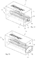
- the housing 12 of the mounting device has rounded edges 88, in particular in the transition between the input side 16 and connecting surfaces 90 and the output side 20 and the connecting surfaces 90, cf. FIGS. 10 and 11 ,
- the structure and operation of the mounting device 10 correspond to FIG FIGS. 10 and 11 the structure and operation of the mounting device according to FIGS. 1 to 9 , It is therefore referred to the above description.
- the mounting device according to FIG. 12 differs from the mounting device 10 according to FIGS. 1 to 9 in that the insertion profile 28 is closed on the circumference, ie the side wall 32 has no insertion profile opening 30 (cf. FIG. 1 ). This means that a section 94 of the insertion region 26 is closed in the direction of the side wall 32, thus providing an insertion profile 28 closed overall on the circumference.
- the circumferentially closed insertion profile 28 is as above with reference to FIGS. 1 to 9 described, in a profiled strip execution area 66 via, which is also circumferentially closed on the output side 20.
- FIG. 12 illustrated embodiment of a mounting device 10 with a circumferentially closed insertion profile 28 is used for a strip assembly 18, which is not (yet) connected to a window 36.
- the attachment portion 42 (see. FIG. 4 ) of the profile strip 22 in the section 94.
- a mounting device 10 according to FIG. 13 has an insertion portion 26 with a funnel-shaped insertion section 96, which extends from the input side 16 into the housing 12 of the mounting device 10 into the insertion profile 28 which is complementary to the cross section of the strip assembly 18 is formed.
- Mounting device 10 shown has a multi-part housing 12 with a first housing part 100 and with a second housing part 102.
- the housing parts 100 and 102 are rigidly connected to each other, for example glued together. But it is possible that the mounting device 10 described below has a one-piece housing 12 only.
- a first housing part 100 of the mounting device 10 according to FIGS. 14 to 19 extends between an input side 16 and an output side 20 along a main axis 14.
- the housing part 100 has an insertion region 26 and a separation region 46.
- a lifting device 48 of the separating region 46 is formed by a material section 104 of the housing part 100, but may additionally or alternatively also be formed by an additional element 50.
- the material section 104 also has a ramp section 56.
- first housing part 100 In the first housing part 100 are, comparable to the mounting device 10 according to FIGS. 1 to 9 , a mold ledge-out portion 66, and a carry-ledge lead-out portion 72 which open on the exit side 20 of the first case 100. There, these areas go into guide channels 106 for the profile strip 22 and 108 for the transport protection strip 24.
- the guide channels 106, 108 are arranged in the second housing part 102.
- a distance between the output side 20 of the first housing part 100 and a thereto adjacent input side of the second housing part 102 may be present.
- the guide channels 106, 108 have funnel-shaped insertion regions.
- the guide channels 106, 108 of the second housing part 102 open into a merging region 110, which serves to reconnect previously separate sections of the transport protection strip 24 and the profile strip 22.
- an indenting portion 112 is provided in the merge area, which cooperates with an upper side of the transport protection strip 24 and pushes the transport protection strip 24 from its upper side into the receiving area 40 of the profile strip 22, cf.
- FIG. 19
- the merging region 110 adjoins an output side 113 of the second housing part 102 facing away from the first housing part 100.
- the pressing portion 112 is an integral part of the housing material of the second housing part 102 and merges seamlessly into the upper boundary of the guide channel 108.
- the indenting section 112 may also be formed by a separate additional element (not shown), for example a metallic indentation block or an indenting roller.
- FIGS. 16 to 19 It is shown how a free end 76 of a last assembly 18 is inserted into the insertion area 26 (an initial state is in FIG FIG. 16 shown). Subsequently, a portion 86 of the transport protection strip 24 in above with reference to FIGS. 1 to 9 described manner separated from the profile strip 22 (see. FIG. 17 ).
- first guide path 116 is largely rectilinear, while the second guide path 114 a has a curved course and thus overall longer than the first guide 116.
- the length dimension 118 between free ends of the transport protection strip 24 and the profile strip 22 corresponds to the difference between the lengths of the guide paths 114 and 116.
Claims (22)
- Dispositif de montage (10) destiné à être utilisé dans un ensemble de baguettes (18) qui comprend une baguette profilée (22) apte à être disposée ou disposée sur une zone de bord (34) d'une vitre de fenêtre (36) d'un véhicule automobile ainsi qu'une baguette de protection de transport (24), dans lequel la baguette de protection de transport (24) est disposée, au moins par une zone partielle de sa section transversale, dans une zone de logement (40) de la baguette profilée (22), caractérisé par le fait que le dispositif de montage (10) présente une zone d'introduction (26) destinée à introduire, dans le dispositif de montage (10), une extrémité libre (76) dudit ensemble de baguettes (18) comprenant la baguette profilée (22) et la baguette de protection de transport (24), ainsi qu'une zone de séparation (46) destinée à séparer la baguette de protection de transport (24) et la baguette profilée (22), dans lequel ladite zone d'introduction (26) permet un positionnement relatif entre l'extrémité libre (76) de l'ensemble de baguettes (18) et la zone de séparation (46).
- Dispositif de montage (10) selon la revendication 1, caractérisé par le fait que la zone d'introduction (26) présente un profilé d'introduction (28) qui est complémentaire, au moins par sections, de la section transversale de l'ensemble de baguettes (18).
- Dispositif de montage (10) selon la revendication 2, caractérisé par le fait que le profilé d'introduction (28) est fermé sur la circonférence ou présente une ouverture de profilé d'introduction (30) dans laquelle peut être disposée la zone de bord (34) de la vitre de fenêtre (36).
- Dispositif de montage (10) selon la revendication 2 ou 3, caractérisé par le fait que le profilé d'introduction (28) est délimité par des portions de paroi d'un boîtier (12) du dispositif de montage (10) et/ou, de préférence, par des sections de guidage et/ou d'entraînement réduisant le frottement.
- Dispositif de montage (10) selon l'une quelconque des revendications précédentes, caractérisé par le fait que la zone de séparation (46) comprend un dispositif de levage (48) ayant une portion de rampe (56) qui s'engage, au moins par sections, sous la baguette de protection de transport (24) et fait sortir celle-ci de la zone de logement (40) de la baguette profilée (22).
- Dispositif de montage (10) selon la revendication 5, caractérisé par le fait que la portion de rampe (56) est formée par une portion (104) d'un ou dudit boîtier (12) du dispositif de montage et/ou par un élément supplémentaire (50) en particulier en forme de lame.
- Dispositif de montage (10) selon l'une quelconque des revendications précédentes, caractérisé par une zone de sortie de baguette profilée (66) et/ou par une zone de sortie de baguette de protection de transport (72).
- Dispositif de montage (10) selon la revendication 7, caractérisé par le fait que ladite zone de sortie de baguette profilée (66) et/ou ladite zone de sortie de baguette de protection de transport (72) est ou sont ouverte(s) aux extrémités.
- Dispositif de montage (10) selon l'une quelconque des revendications précédentes, caractérisé par le fait que ladite zone de sortie de baguette profilée (66) et/ou ladite zone de sortie de baguette de protection de transport (72) est ou sont fermée(s) aux extrémités.
- Dispositif de montage (10) selon l'une quelconque des revendications 1 à 9, comprenant une zone de jonction (110) pour réunir une portion (86) de la baguette de protection de transport (24) et de la baguette profilée (22), qui est séparée de la zone de logement (40) de la baguette profilée (22).
- Dispositif de montage (10) selon la revendication 10, caractérisé par le fait qu'une portion destinée à faire entrer par pression (112) est prévue dans ladite zone de jonction (110), qui sert à faire entrer par pression la baguette de protection de transport (24), au moins par une zone partielle de sa section transversale, dans la zone de logement (40) de la baguette profilée (22).
- Dispositif de montage (10) selon la revendication 11, caractérisé par le fait que ladite portion destinée à faire entrer par pression (112) est formée par une portion d'un boîtier (12) du dispositif de montage (10) et/ou par un élément supplémentaire en particulier en forme de bloc ou de rouleau.
- Dispositif de montage (10) selon l'une quelconque des revendications précédentes, caractérisé par le fait que le dispositif de montage comprend un boîtier (12) monobloc.
- Dispositif de montage (10) selon l'une quelconque des revendications 1 à 12, caractérisé par le fait que le dispositif de montage (10) comprend un boîtier (12) en plusieurs parties, dans lequel ledit boîtier (12) comprend une première partie de boîtier (100) qui présente au moins la zone d'introduction (26) et la zone de séparation (46), ainsi qu'une deuxième partie de boîtier (102) qui comprend au moins une zone de jonction (110) selon l'une quelconque des revendications 10 à 12.
- Dispositif de montage (10) selon la revendication 14, caractérisé par le fait que les parties de boîtier (100, 102) sont reliées entre elles de manière rigide ou mobile.
- Dispositif de montage (10) selon l'une quelconque des revendications précédentes, caractérisé par un dispositif d'entraînement pour générer un mouvement relatif (78, 80) dirigé le long de l'ensemble de baguettes (18), entre l'ensemble de baguettes (18) et le dispositif de montage (10) .
- Procédé pour être mis en oeuvre dans un ensemble de baguettes (18) qui comprend une baguette profilée (22) apte à être disposée ou disposée sur une zone de bord (34) d'une vitre de fenêtre (36) d'un véhicule automobile ainsi qu'une baguette de protection de transport (24), dans lequel la baguette de protection de transport (24) est disposée, au moins par une zone partielle de sa section transversale, dans une zone de logement (40) de la baguette profilée (22), caractérisé par l'introduction d'une extrémité libre dudit ensemble de baguettes (18) comprenant la baguette profilée (22) et la baguette de protection de transport (24), dans une zone d'introduction (26) d'un dispositif de montage (10), par un positionnement relatif entre ladite extrémité libre (76) de l'ensemble de baguettes (18) et une zone de séparation (46) du dispositif de montage (10) dans la zone d'introduction (26), et par la séparation d'une extrémité libre de la baguette de protection de transport (24) et de la baguette profilée (22) dans la zone de séparation (46).
- Procédé selon la revendication 17, caractérisé par un mouvement relatif (78, 80) de la zone d'introduction (26) et de la zone de séparation (46) d'une part et de l'ensemble de baguettes (18) d'autre part, le long de l'ensemble de baguettes (18) pour séparer, de la baguette profilée (22), une portion (86) de la baguette de protection de transport (24), qui est contiguë à l'extrémité libre de baguette de protection de transport (24) .
- Procédé selon la revendication 18, caractérisé par le guidage de la baguette profilée (22) le long d'un premier chemin de guidage (116) qui présente une première longueur, par le guidage d'une portion (86) de la baguette de protection de transport (24), qui est séparée de la baguette profilée (22), le long d'un deuxième chemin de guidage (114) qui présente une deuxième longueur différente de la première longueur, et par l'action de réunir la baguette de protection de transport (24) et la baguette profilée (22) et par l'action de faire entrer par pression au moins une zone partielle de la section transversale de la baguette de protection de transport (24) dans la zone de logement (40) de la baguette profilée (22).
- Procédé selon la revendication 19, caractérisé par le fait que la deuxième longueur est supérieure à la première longueur.
- Procédé selon la revendication 19 ou 20, caractérisé par le fait que l'ensemble de baguettes (18) qui est introduit dans la zone d'introduction (26),a) présente des extrémités de la baguette profilée (22) et de la baguette de protection de transport (24), qui sont à fleur l'une de l'autre, et que, après avoir engagé par pression au moins une zone partielle de la section transversale de la baguette de protection de transport (24) dans la zone de logement (40) de la baguette profilée (22), ces extrémités sont décalées d'une mesure de longueur (118) qui correspond à la différence des longueurs des chemins de guidage (116, 114), oub) présente des extrémités de la baguette profilée (22) et de la baguette de protection de transport (24), qui sont décalées l'une par rapport à l'autre d'une première mesure de longueur, et que, après avoir engagé par pression au moins une zone partielle de la section transversale de la baguette de protection de transport (24) dans la zone de logement (40) de la baguette profilée (22), ces extrémités sont décalées d'une deuxième mesure de longueur différente de la première mesure de longueur, la valeur absolue de la différence entre la première mesure de longueur et la deuxième mesure de longueur correspondant à la différence des longueurs des chemins de guidage (116, 114).
- Utilisation d'un dispositif de montage (10) selon l'une des revendications 1 à 16, pour la mise en oeuvre d'un procédé selon l'une quelconque des revendications 17 à 21.
Priority Applications (7)
| Application Number | Priority Date | Filing Date | Title |
|---|---|---|---|
| ES17162529T ES2748871T3 (es) | 2017-03-23 | 2017-03-23 | Dispositivo de montaje para el uso en una disposición de barras y procedimiento para la realización en una disposición de barras |
| EP17162529.6A EP3378688B1 (fr) | 2017-03-23 | 2017-03-23 | Dispositif de montage à utiliser pour un système de baguettes et procédé d'exécution pour un système de baguettes |
| DE202017104920.5U DE202017104920U1 (de) | 2017-03-23 | 2017-08-16 | Montagevorrichtung zur Verwendung bei einer Leistenanordnung |
| JP2019548331A JP6736783B2 (ja) | 2017-03-23 | 2018-02-06 | ストリップ組立体に使用するための取付装置、及びストリップ組立体によって実施される方法 |
| US16/340,394 US11207766B2 (en) | 2017-03-23 | 2018-02-06 | Mounting device for use in a strip assembly and method for carrying out in a strip assembly |
| PCT/EP2018/052923 WO2018171972A1 (fr) | 2017-03-23 | 2018-02-06 | Dispositif de montage destiné à être utilisé avec un ensemble de baguettes et procédé de mise en œuvre pour un ensemble de baguettes |
| CN201880015169.0A CN110382270B (zh) | 2017-03-23 | 2018-02-06 | 用于条带组件的安装设备和用于在条带组件中执行的方法 |
Applications Claiming Priority (1)
| Application Number | Priority Date | Filing Date | Title |
|---|---|---|---|
| EP17162529.6A EP3378688B1 (fr) | 2017-03-23 | 2017-03-23 | Dispositif de montage à utiliser pour un système de baguettes et procédé d'exécution pour un système de baguettes |
Publications (2)
| Publication Number | Publication Date |
|---|---|
| EP3378688A1 EP3378688A1 (fr) | 2018-09-26 |
| EP3378688B1 true EP3378688B1 (fr) | 2019-08-07 |
Family
ID=58410187
Family Applications (1)
| Application Number | Title | Priority Date | Filing Date |
|---|---|---|---|
| EP17162529.6A Active EP3378688B1 (fr) | 2017-03-23 | 2017-03-23 | Dispositif de montage à utiliser pour un système de baguettes et procédé d'exécution pour un système de baguettes |
Country Status (7)
| Country | Link |
|---|---|
| US (1) | US11207766B2 (fr) |
| EP (1) | EP3378688B1 (fr) |
| JP (1) | JP6736783B2 (fr) |
| CN (1) | CN110382270B (fr) |
| DE (1) | DE202017104920U1 (fr) |
| ES (1) | ES2748871T3 (fr) |
| WO (1) | WO2018171972A1 (fr) |
Families Citing this family (1)
| Publication number | Priority date | Publication date | Assignee | Title |
|---|---|---|---|---|
| DE102019127378A1 (de) * | 2019-10-10 | 2021-04-15 | Elkamet Kunststofftechnik Gmbh | Leistenanordnung und Verfahren zur Herstellung |
Family Cites Families (22)
| Publication number | Priority date | Publication date | Assignee | Title |
|---|---|---|---|---|
| FR719225A (fr) * | 1931-06-27 | 1932-02-03 | Pince sans vis pour fil de trolley | |
| US3744113A (en) * | 1971-03-22 | 1973-07-10 | Standard Products Co | Lock strip inserting tool |
| FR2664226B2 (fr) * | 1990-04-05 | 1992-09-25 | Mesnel Sa Ets | Procede et dispositif pour la mise en place d'un profile a section en u sur un rebord de carrosserie d'automobile ou similaire. |
| US5445780A (en) * | 1992-08-26 | 1995-08-29 | Tokai Kogyo Kabushiki Kaisha | Assembly of a windshield glass and a weather strip having a partly modified cross section and method of manufacturing same |
| US6388185B1 (en) | 1998-08-07 | 2002-05-14 | California Institute Of Technology | Microfabricated thermoelectric power-generation devices |
| US6868595B1 (en) * | 1999-01-15 | 2005-03-22 | Rubrail Tool, Inc. | Multi-purpose rub rail installation tool |
| JP2001130594A (ja) | 1999-11-08 | 2001-05-15 | Showa Highpolymer Co Ltd | スライダー付きプラスチックチャック及び該プラスチックチャックを備えた袋体並びにその袋体の製造方法 |
| DE20008555U1 (de) | 2000-05-12 | 2000-08-17 | Elkamet Kunststofftechnik Gmbh | Abdichtungs-Anordnung für Fahrzeugscheiben |
| US6679027B2 (en) | 2000-11-29 | 2004-01-20 | Reynolds Consumer Products, Inc. | Resealable closure mechanism having a slider device and methods |
| NZ532407A (fr) * | 2001-10-17 | 2005-12-23 | Illinois Tool Works | |
| US6739755B2 (en) | 2001-10-24 | 2004-05-25 | Reynolds Consumer Products, Inc. | Leak proof closure mechanism for resealable bag |
| US6976787B2 (en) * | 2002-04-11 | 2005-12-20 | Illinois Tool Works Inc. | Slider-operated rocking zipper for reclosable packaging |
| US6860067B2 (en) * | 2002-06-13 | 2005-03-01 | Ford Global Technologies, Llc | Method and system for determining weather strip fit for a closure panel of a vehicle |
| ES2454619T3 (es) | 2004-07-02 | 2014-04-11 | Kunststoff-Technik Scherer & Trier Gmbh & Co. Kg | Moldura perfilada de borde hecha de plástico y cabeza de montaje |
| DE202008006986U1 (de) | 2008-05-23 | 2009-10-01 | Elkamet Kunststofftechnik Gmbh | Profilelement zum Verbinden einer Fahrzeugscheibe mit einem Wasserkasten |
| FR2945521B1 (fr) | 2009-05-15 | 2011-05-13 | Rehau Sa | Cle de transport a extraction aisee pour profiles creux ou pieces creuses deformables |
| FR2952900B1 (fr) | 2009-11-26 | 2012-02-24 | Peugeot Citroen Automobiles Sa | Cle extractible pour joint de vitrage et procede d'extraction s'y rapportant |
| DE102011054801B4 (de) | 2011-10-25 | 2015-08-20 | Elkamet Kunststofftechnik Gmbh | Kederleiste zum Schutz einer Profilleiste |
| FR2995563B1 (fr) | 2012-09-14 | 2014-08-29 | Saint Gobain | Systeme de joint pour vitrage de vehicule, vitrage equipe du systeme et procede de montage du vitrage. |
| DE102012110472B3 (de) | 2012-11-01 | 2014-03-27 | Elkamet Kunststofftechnik Gmbh | Montage- und Transportprofil für ein Profilelement |
| FR3020994B1 (fr) * | 2014-05-16 | 2016-05-27 | Saint Gobain | Systeme de joint pour vitrage de vehicule, vitrage equipe du systeme et procede de montage du vitrage. |
| US9669882B2 (en) * | 2015-07-28 | 2017-06-06 | GM Global Technology Operations LLC | Panel sealing apparatus and a method of assembling the panel sealing apparatus |
-
2017
- 2017-03-23 EP EP17162529.6A patent/EP3378688B1/fr active Active
- 2017-03-23 ES ES17162529T patent/ES2748871T3/es active Active
- 2017-08-16 DE DE202017104920.5U patent/DE202017104920U1/de active Active
-
2018
- 2018-02-06 JP JP2019548331A patent/JP6736783B2/ja active Active
- 2018-02-06 US US16/340,394 patent/US11207766B2/en active Active
- 2018-02-06 WO PCT/EP2018/052923 patent/WO2018171972A1/fr active Application Filing
- 2018-02-06 CN CN201880015169.0A patent/CN110382270B/zh active Active
Non-Patent Citations (1)
| Title |
|---|
| None * |
Also Published As
| Publication number | Publication date |
|---|---|
| CN110382270B (zh) | 2020-12-04 |
| WO2018171972A1 (fr) | 2018-09-27 |
| DE202017104920U1 (de) | 2017-08-29 |
| JP2020509965A (ja) | 2020-04-02 |
| ES2748871T3 (es) | 2020-03-18 |
| US20190240820A1 (en) | 2019-08-08 |
| US11207766B2 (en) | 2021-12-28 |
| JP6736783B2 (ja) | 2020-08-05 |
| CN110382270A (zh) | 2019-10-25 |
| EP3378688A1 (fr) | 2018-09-26 |
Similar Documents
| Publication | Publication Date | Title |
|---|---|---|
| DE102006017538B4 (de) | Rolloanordnung für ein Fahrzeug | |
| EP3103665B1 (fr) | Baguette profilée, système et procédé de fabrication d'une baguette profilée | |
| DE102013107173B4 (de) | Verfahren zum Herstellen einer Lamelle mit einem Dekorelement sowie Lamelle mit Dekorelement | |
| DE102015100189A1 (de) | Sitzschiene zur Aufnahme eines Sitzes | |
| AT518076B1 (de) | Schubladenseitenwand | |
| DE3827875C2 (de) | Ersatzwischleiste und Montageverfahren dazu | |
| EP2935739B1 (fr) | Dispositif de recouvrement pour un module flasque de retenue pouvant être amené en accouplement libérable a l'aide d'un module a clavettes de fermeture créant une liaison entre une porte de véhicule et un cadre de paroi latérale sur une carrosserie de véhicule | |
| WO2013120699A1 (fr) | Système d'ombrage d'un véhicule composé de deux unités d'ombrage et procédé de montage d'un système d'ombrage | |
| EP3378688B1 (fr) | Dispositif de montage à utiliser pour un système de baguettes et procédé d'exécution pour un système de baguettes | |
| EP2106984B1 (fr) | Revêtement à plis | |
| DE102007024250A1 (de) | Auszugsprofil für Fensterblende | |
| DE102005032564B4 (de) | Rahmenanordnung für die verschiebbare Lagerung eines öffnungsfähigen Fahrzeug-Dachteils | |
| DE102018124630A1 (de) | Verfahren zur Positionierung einer Zierleiste und Kraftfahrzeugkomponente | |
| WO2008119706A1 (fr) | Procédé de production d'un système d'étanchéité, notamment pour automobile, comprenant un élément d'étanchéité et un support, et système d'étanchéité correspondant | |
| DE102019205410A1 (de) | Dachanordnung an einem Fahrzeug sowie Fahrzeug mit einer derartigen Dachanordnung | |
| EP3419845A1 (fr) | Ensemble de véhicule automobile, unité de prémontage, baguette profilée et procédé de montage d'un ensemble de véhicule automobile | |
| DE10210968C1 (de) | Gebogenes Strangpreßprofil | |
| DE102017121939A1 (de) | Fahrzeugdachrahmen mit Kabelkanal und Verfahren zu dessen Herstellung | |
| DE102014113005B4 (de) | Verfahren zum Auseinanderbau eines Verbundprofils und Demontagewerkzeug zur Durchführung des Verfahrens | |
| DE102008031381B4 (de) | Vorrichtung zum Anbringen von Dichtungsprofilen an Klebeflächen | |
| EP0997211B1 (fr) | Procédé et appareil pour fabriquer une connexion angulaire d'éléments de revêtement | |
| DE10256181A1 (de) | Vorrichtung zur automatischen Betätigung einer Kraftfahrzeugschiebetür | |
| DE202007008187U1 (de) | Auszugsprofil für Fensterblende | |
| DE102015121115A1 (de) | Dichtung, sowie Pfosten-Riegel-Anordnung | |
| DE102020119459A1 (de) | Rolloanordnung für ein Fahrzeug |
Legal Events
| Date | Code | Title | Description |
|---|---|---|---|
| PUAI | Public reference made under article 153(3) epc to a published international application that has entered the european phase |
Free format text: ORIGINAL CODE: 0009012 |
|
| STAA | Information on the status of an ep patent application or granted ep patent |
Free format text: STATUS: REQUEST FOR EXAMINATION WAS MADE |
|
| 17P | Request for examination filed |
Effective date: 20170823 |
|
| AK | Designated contracting states |
Kind code of ref document: A1 Designated state(s): AL AT BE BG CH CY CZ DE DK EE ES FI FR GB GR HR HU IE IS IT LI LT LU LV MC MK MT NL NO PL PT RO RS SE SI SK SM TR |
|
| AX | Request for extension of the european patent |
Extension state: BA ME |
|
| GRAJ | Information related to disapproval of communication of intention to grant by the applicant or resumption of examination proceedings by the epo deleted |
Free format text: ORIGINAL CODE: EPIDOSDIGR1 |
|
| GRAP | Despatch of communication of intention to grant a patent |
Free format text: ORIGINAL CODE: EPIDOSNIGR1 |
|
| GRAP | Despatch of communication of intention to grant a patent |
Free format text: ORIGINAL CODE: EPIDOSNIGR1 |
|
| STAA | Information on the status of an ep patent application or granted ep patent |
Free format text: STATUS: GRANT OF PATENT IS INTENDED |
|
| INTG | Intention to grant announced |
Effective date: 20181128 |
|
| GRAJ | Information related to disapproval of communication of intention to grant by the applicant or resumption of examination proceedings by the epo deleted |
Free format text: ORIGINAL CODE: EPIDOSDIGR1 |
|
| STAA | Information on the status of an ep patent application or granted ep patent |
Free format text: STATUS: REQUEST FOR EXAMINATION WAS MADE |
|
| GRAP | Despatch of communication of intention to grant a patent |
Free format text: ORIGINAL CODE: EPIDOSNIGR1 |
|
| STAA | Information on the status of an ep patent application or granted ep patent |
Free format text: STATUS: GRANT OF PATENT IS INTENDED |
|
| INTC | Intention to grant announced (deleted) | ||
| INTG | Intention to grant announced |
Effective date: 20190215 |
|
| GRAS | Grant fee paid |
Free format text: ORIGINAL CODE: EPIDOSNIGR3 |
|
| GRAA | (expected) grant |
Free format text: ORIGINAL CODE: 0009210 |
|
| STAA | Information on the status of an ep patent application or granted ep patent |
Free format text: STATUS: THE PATENT HAS BEEN GRANTED |
|
| AK | Designated contracting states |
Kind code of ref document: B1 Designated state(s): AL AT BE BG CH CY CZ DE DK EE ES FI FR GB GR HR HU IE IS IT LI LT LU LV MC MK MT NL NO PL PT RO RS SE SI SK SM TR |
|
| REG | Reference to a national code |
Ref country code: GB Ref legal event code: FG4D Free format text: NOT ENGLISH |
|
| REG | Reference to a national code |
Ref country code: CH Ref legal event code: EP Ref country code: AT Ref legal event code: REF Ref document number: 1163283 Country of ref document: AT Kind code of ref document: T Effective date: 20190815 |
|
| REG | Reference to a national code |
Ref country code: DE Ref legal event code: R096 Ref document number: 502017001927 Country of ref document: DE |
|
| REG | Reference to a national code |
Ref country code: IE Ref legal event code: FG4D Free format text: LANGUAGE OF EP DOCUMENT: GERMAN |
|
| REG | Reference to a national code |
Ref country code: NL Ref legal event code: MP Effective date: 20190807 |
|
| REG | Reference to a national code |
Ref country code: LT Ref legal event code: MG4D |
|
| PG25 | Lapsed in a contracting state [announced via postgrant information from national office to epo] |
Ref country code: FI Free format text: LAPSE BECAUSE OF FAILURE TO SUBMIT A TRANSLATION OF THE DESCRIPTION OR TO PAY THE FEE WITHIN THE PRESCRIBED TIME-LIMIT Effective date: 20190807 Ref country code: HR Free format text: LAPSE BECAUSE OF FAILURE TO SUBMIT A TRANSLATION OF THE DESCRIPTION OR TO PAY THE FEE WITHIN THE PRESCRIBED TIME-LIMIT Effective date: 20190807 Ref country code: SE Free format text: LAPSE BECAUSE OF FAILURE TO SUBMIT A TRANSLATION OF THE DESCRIPTION OR TO PAY THE FEE WITHIN THE PRESCRIBED TIME-LIMIT Effective date: 20190807 Ref country code: NO Free format text: LAPSE BECAUSE OF FAILURE TO SUBMIT A TRANSLATION OF THE DESCRIPTION OR TO PAY THE FEE WITHIN THE PRESCRIBED TIME-LIMIT Effective date: 20191107 Ref country code: PT Free format text: LAPSE BECAUSE OF FAILURE TO SUBMIT A TRANSLATION OF THE DESCRIPTION OR TO PAY THE FEE WITHIN THE PRESCRIBED TIME-LIMIT Effective date: 20191209 Ref country code: LT Free format text: LAPSE BECAUSE OF FAILURE TO SUBMIT A TRANSLATION OF THE DESCRIPTION OR TO PAY THE FEE WITHIN THE PRESCRIBED TIME-LIMIT Effective date: 20190807 Ref country code: NL Free format text: LAPSE BECAUSE OF FAILURE TO SUBMIT A TRANSLATION OF THE DESCRIPTION OR TO PAY THE FEE WITHIN THE PRESCRIBED TIME-LIMIT Effective date: 20190807 Ref country code: BG Free format text: LAPSE BECAUSE OF FAILURE TO SUBMIT A TRANSLATION OF THE DESCRIPTION OR TO PAY THE FEE WITHIN THE PRESCRIBED TIME-LIMIT Effective date: 20191107 |
|
| PG25 | Lapsed in a contracting state [announced via postgrant information from national office to epo] |
Ref country code: GR Free format text: LAPSE BECAUSE OF FAILURE TO SUBMIT A TRANSLATION OF THE DESCRIPTION OR TO PAY THE FEE WITHIN THE PRESCRIBED TIME-LIMIT Effective date: 20191108 Ref country code: LV Free format text: LAPSE BECAUSE OF FAILURE TO SUBMIT A TRANSLATION OF THE DESCRIPTION OR TO PAY THE FEE WITHIN THE PRESCRIBED TIME-LIMIT Effective date: 20190807 Ref country code: AL Free format text: LAPSE BECAUSE OF FAILURE TO SUBMIT A TRANSLATION OF THE DESCRIPTION OR TO PAY THE FEE WITHIN THE PRESCRIBED TIME-LIMIT Effective date: 20190807 Ref country code: RS Free format text: LAPSE BECAUSE OF FAILURE TO SUBMIT A TRANSLATION OF THE DESCRIPTION OR TO PAY THE FEE WITHIN THE PRESCRIBED TIME-LIMIT Effective date: 20190807 Ref country code: IS Free format text: LAPSE BECAUSE OF FAILURE TO SUBMIT A TRANSLATION OF THE DESCRIPTION OR TO PAY THE FEE WITHIN THE PRESCRIBED TIME-LIMIT Effective date: 20191207 |
|
| REG | Reference to a national code |
Ref country code: ES Ref legal event code: FG2A Ref document number: 2748871 Country of ref document: ES Kind code of ref document: T3 Effective date: 20200318 |
|
| PG25 | Lapsed in a contracting state [announced via postgrant information from national office to epo] |
Ref country code: TR Free format text: LAPSE BECAUSE OF FAILURE TO SUBMIT A TRANSLATION OF THE DESCRIPTION OR TO PAY THE FEE WITHIN THE PRESCRIBED TIME-LIMIT Effective date: 20190807 |
|
| PG25 | Lapsed in a contracting state [announced via postgrant information from national office to epo] |
Ref country code: EE Free format text: LAPSE BECAUSE OF FAILURE TO SUBMIT A TRANSLATION OF THE DESCRIPTION OR TO PAY THE FEE WITHIN THE PRESCRIBED TIME-LIMIT Effective date: 20190807 Ref country code: PL Free format text: LAPSE BECAUSE OF FAILURE TO SUBMIT A TRANSLATION OF THE DESCRIPTION OR TO PAY THE FEE WITHIN THE PRESCRIBED TIME-LIMIT Effective date: 20190807 Ref country code: RO Free format text: LAPSE BECAUSE OF FAILURE TO SUBMIT A TRANSLATION OF THE DESCRIPTION OR TO PAY THE FEE WITHIN THE PRESCRIBED TIME-LIMIT Effective date: 20190807 Ref country code: DK Free format text: LAPSE BECAUSE OF FAILURE TO SUBMIT A TRANSLATION OF THE DESCRIPTION OR TO PAY THE FEE WITHIN THE PRESCRIBED TIME-LIMIT Effective date: 20190807 |
|
| PG25 | Lapsed in a contracting state [announced via postgrant information from national office to epo] |
Ref country code: SK Free format text: LAPSE BECAUSE OF FAILURE TO SUBMIT A TRANSLATION OF THE DESCRIPTION OR TO PAY THE FEE WITHIN THE PRESCRIBED TIME-LIMIT Effective date: 20190807 Ref country code: CZ Free format text: LAPSE BECAUSE OF FAILURE TO SUBMIT A TRANSLATION OF THE DESCRIPTION OR TO PAY THE FEE WITHIN THE PRESCRIBED TIME-LIMIT Effective date: 20190807 Ref country code: IS Free format text: LAPSE BECAUSE OF FAILURE TO SUBMIT A TRANSLATION OF THE DESCRIPTION OR TO PAY THE FEE WITHIN THE PRESCRIBED TIME-LIMIT Effective date: 20200224 Ref country code: SM Free format text: LAPSE BECAUSE OF FAILURE TO SUBMIT A TRANSLATION OF THE DESCRIPTION OR TO PAY THE FEE WITHIN THE PRESCRIBED TIME-LIMIT Effective date: 20190807 |
|
| REG | Reference to a national code |
Ref country code: DE Ref legal event code: R097 Ref document number: 502017001927 Country of ref document: DE |
|
| PLBE | No opposition filed within time limit |
Free format text: ORIGINAL CODE: 0009261 |
|
| STAA | Information on the status of an ep patent application or granted ep patent |
Free format text: STATUS: NO OPPOSITION FILED WITHIN TIME LIMIT |
|
| PG2D | Information on lapse in contracting state deleted |
Ref country code: IS |
|
| 26N | No opposition filed |
Effective date: 20200603 |
|
| PG25 | Lapsed in a contracting state [announced via postgrant information from national office to epo] |
Ref country code: SI Free format text: LAPSE BECAUSE OF FAILURE TO SUBMIT A TRANSLATION OF THE DESCRIPTION OR TO PAY THE FEE WITHIN THE PRESCRIBED TIME-LIMIT Effective date: 20190807 |
|
| PG25 | Lapsed in a contracting state [announced via postgrant information from national office to epo] |
Ref country code: MC Free format text: LAPSE BECAUSE OF FAILURE TO SUBMIT A TRANSLATION OF THE DESCRIPTION OR TO PAY THE FEE WITHIN THE PRESCRIBED TIME-LIMIT Effective date: 20190807 |
|
| REG | Reference to a national code |
Ref country code: CH Ref legal event code: PL |
|
| REG | Reference to a national code |
Ref country code: BE Ref legal event code: MM Effective date: 20200331 |
|
| PG25 | Lapsed in a contracting state [announced via postgrant information from national office to epo] |
Ref country code: LU Free format text: LAPSE BECAUSE OF NON-PAYMENT OF DUE FEES Effective date: 20200323 |
|
| PG25 | Lapsed in a contracting state [announced via postgrant information from national office to epo] |
Ref country code: LI Free format text: LAPSE BECAUSE OF NON-PAYMENT OF DUE FEES Effective date: 20200331 Ref country code: CH Free format text: LAPSE BECAUSE OF NON-PAYMENT OF DUE FEES Effective date: 20200331 Ref country code: IE Free format text: LAPSE BECAUSE OF NON-PAYMENT OF DUE FEES Effective date: 20200323 |
|
| PG25 | Lapsed in a contracting state [announced via postgrant information from national office to epo] |
Ref country code: BE Free format text: LAPSE BECAUSE OF NON-PAYMENT OF DUE FEES Effective date: 20200331 |
|
| PG25 | Lapsed in a contracting state [announced via postgrant information from national office to epo] |
Ref country code: MT Free format text: LAPSE BECAUSE OF FAILURE TO SUBMIT A TRANSLATION OF THE DESCRIPTION OR TO PAY THE FEE WITHIN THE PRESCRIBED TIME-LIMIT Effective date: 20190807 Ref country code: CY Free format text: LAPSE BECAUSE OF FAILURE TO SUBMIT A TRANSLATION OF THE DESCRIPTION OR TO PAY THE FEE WITHIN THE PRESCRIBED TIME-LIMIT Effective date: 20190807 |
|
| PG25 | Lapsed in a contracting state [announced via postgrant information from national office to epo] |
Ref country code: MK Free format text: LAPSE BECAUSE OF FAILURE TO SUBMIT A TRANSLATION OF THE DESCRIPTION OR TO PAY THE FEE WITHIN THE PRESCRIBED TIME-LIMIT Effective date: 20190807 |
|
| PGFP | Annual fee paid to national office [announced via postgrant information from national office to epo] |
Ref country code: FR Payment date: 20230320 Year of fee payment: 7 |
|
| REG | Reference to a national code |
Ref country code: AT Ref legal event code: MM01 Ref document number: 1163283 Country of ref document: AT Kind code of ref document: T Effective date: 20220323 |
|
| P01 | Opt-out of the competence of the unified patent court (upc) registered |
Effective date: 20230515 |
|
| PG25 | Lapsed in a contracting state [announced via postgrant information from national office to epo] |
Ref country code: AT Free format text: LAPSE BECAUSE OF NON-PAYMENT OF DUE FEES Effective date: 20220323 |
|
| PGFP | Annual fee paid to national office [announced via postgrant information from national office to epo] |
Ref country code: IT Payment date: 20230331 Year of fee payment: 7 Ref country code: ES Payment date: 20230414 Year of fee payment: 7 Ref country code: DE Payment date: 20230511 Year of fee payment: 7 |
|
| PGFP | Annual fee paid to national office [announced via postgrant information from national office to epo] |
Ref country code: GB Payment date: 20240314 Year of fee payment: 8 |