EP3378688B1 - Mounting device for use in an edge strip assembly and method for implementation in an edge strip assembly - Google Patents
Mounting device for use in an edge strip assembly and method for implementation in an edge strip assembly Download PDFInfo
- Publication number
- EP3378688B1 EP3378688B1 EP17162529.6A EP17162529A EP3378688B1 EP 3378688 B1 EP3378688 B1 EP 3378688B1 EP 17162529 A EP17162529 A EP 17162529A EP 3378688 B1 EP3378688 B1 EP 3378688B1
- Authority
- EP
- European Patent Office
- Prior art keywords
- strip
- mounting device
- profile
- transport protection
- area
- Prior art date
- Legal status (The legal status is an assumption and is not a legal conclusion. Google has not performed a legal analysis and makes no representation as to the accuracy of the status listed.)
- Active
Links
Images


Classifications
-
- B—PERFORMING OPERATIONS; TRANSPORTING
- B25—HAND TOOLS; PORTABLE POWER-DRIVEN TOOLS; MANIPULATORS
- B25B—TOOLS OR BENCH DEVICES NOT OTHERWISE PROVIDED FOR, FOR FASTENING, CONNECTING, DISENGAGING OR HOLDING
- B25B27/00—Hand tools, specially adapted for fitting together or separating parts or objects whether or not involving some deformation, not otherwise provided for
- B25B27/0092—Tools moving along strips, e.g. decorating or sealing strips, to insert them in, or remove them from, grooves or profiles
-
- B—PERFORMING OPERATIONS; TRANSPORTING
- B23—MACHINE TOOLS; METAL-WORKING NOT OTHERWISE PROVIDED FOR
- B23P—METAL-WORKING NOT OTHERWISE PROVIDED FOR; COMBINED OPERATIONS; UNIVERSAL MACHINE TOOLS
- B23P19/00—Machines for simply fitting together or separating metal parts or objects, or metal and non-metal parts, whether or not involving some deformation; Tools or devices therefor so far as not provided for in other classes
- B23P19/04—Machines for simply fitting together or separating metal parts or objects, or metal and non-metal parts, whether or not involving some deformation; Tools or devices therefor so far as not provided for in other classes for assembling or disassembling parts
- B23P19/047—Machines for simply fitting together or separating metal parts or objects, or metal and non-metal parts, whether or not involving some deformation; Tools or devices therefor so far as not provided for in other classes for assembling or disassembling parts for flexible profiles, e.g. sealing or decorating strips in grooves or on other profiles by devices moving along the flexible profile
-
- B—PERFORMING OPERATIONS; TRANSPORTING
- B25—HAND TOOLS; PORTABLE POWER-DRIVEN TOOLS; MANIPULATORS
- B25B—TOOLS OR BENCH DEVICES NOT OTHERWISE PROVIDED FOR, FOR FASTENING, CONNECTING, DISENGAGING OR HOLDING
- B25B27/00—Hand tools, specially adapted for fitting together or separating parts or objects whether or not involving some deformation, not otherwise provided for
- B25B27/0035—Hand tools, specially adapted for fitting together or separating parts or objects whether or not involving some deformation, not otherwise provided for for motor-vehicles
-
- B—PERFORMING OPERATIONS; TRANSPORTING
- B60—VEHICLES IN GENERAL
- B60J—WINDOWS, WINDSCREENS, NON-FIXED ROOFS, DOORS, OR SIMILAR DEVICES FOR VEHICLES; REMOVABLE EXTERNAL PROTECTIVE COVERINGS SPECIALLY ADAPTED FOR VEHICLES
- B60J10/00—Sealing arrangements
-
- B—PERFORMING OPERATIONS; TRANSPORTING
- B60—VEHICLES IN GENERAL
- B60J—WINDOWS, WINDSCREENS, NON-FIXED ROOFS, DOORS, OR SIMILAR DEVICES FOR VEHICLES; REMOVABLE EXTERNAL PROTECTIVE COVERINGS SPECIALLY ADAPTED FOR VEHICLES
- B60J10/00—Sealing arrangements
- B60J10/30—Sealing arrangements characterised by the fastening means
-
- B—PERFORMING OPERATIONS; TRANSPORTING
- B60—VEHICLES IN GENERAL
- B60J—WINDOWS, WINDSCREENS, NON-FIXED ROOFS, DOORS, OR SIMILAR DEVICES FOR VEHICLES; REMOVABLE EXTERNAL PROTECTIVE COVERINGS SPECIALLY ADAPTED FOR VEHICLES
- B60J10/00—Sealing arrangements
- B60J10/70—Sealing arrangements specially adapted for windows or windscreens
Definitions
- the invention relates to a mounting device with the features of the preamble of claim 1.
- the profile strip is connected after its preparation with the edge region of the windshield, usually glued.
- This assembly step is typically performed at suppliers so that the suppliers can provide an assembly to an automotive manufacturer that includes the windshield and the trim associated with the windshield.
- This assembly is then connected as part of a final assembly of a motor vehicle with a windshield receptacle of a motor vehicle body;
- the adjacent vehicle component is joined to the profile strip.
- the connecting portion of the profiled strip intended for connection to the adjacent component is of the Windscreen off and is thus exposed to mechanical influences.
- the assembly can be transported to save space and "standing", so that the windshield can be transported upright.
- the windshield is protected during transport against damage to the lower edge region.
- Such protection is ensured by the fact that the windshield is supported during its transport on the connecting portion of the profile strip.
- the transport protection strip is removed again from the receiving area of the profile strip, so that the connecting portion with the adjacent vehicle component, in particular with the water box cover, can be connected.
- the transport protection strip is then disposed of.
- the above-mentioned additional handling sections simplify the removal of the transport protection strip from the receiving area of the profile strip.
- the transport protection strip and the handling sections must first be manufactured as individual parts and then be mounted by the supplier on the profile strip. After the assembly has been transported to the motor vehicle manufacturer, the motor vehicle manufacturer must then dismantle the transport protection strip and the handling sections again. Finally, the transport protection strip and the handling sections must be collected and disposed of.
- a hand tool which has an annular handle and a shaft with a ball head arranged at the end.
- the ball head can be inserted into the receiving area of a profile strip in order to remove an existing in the receiving area Kederang from the receiving area by displacement of the ball head along the strip arrangement.
- a mounting tool for mounting a rubber insert bar in a receiving area of a rubber main bar is known.
- This mounting tool has an opening for the passage of the rubber insert bar, which is gradually introduced in the course of a displacement of the tool along the main rubber strip in the receiving area.
- the mounting device according to the invention has two essential areas.
- the insertion area serves to introduce the free end of the strip assembly in the mounting device.
- a relative positioning between the free end of the strip assembly and the separation area, which is designed to separate the transport protection strip from the profile strip, allows.
- the mounting device according to the invention has the advantage that (known from the prior art) can be omitted separate, to be attached to the transport protection strip handling sections.
- the mounting device according to the invention is reusable for a variety of strip assemblies. After insertion of the free end of the strip assembly in the insertion and separating the transport protection strip from the profile strip, the mounting device can again from the at least sections removed components "transport protection strip and profile strip" and used for a further strip arrangement.
- the mounting device can thus be kept stationary in a manufacturing environment of a supplier or a motor vehicle manufacturer and does not have to be "transported along" with vehicle windows and strip assemblies.
- the insertion region has an insertion profile which is at least partially complementary to the cross section of the strip arrangement.
- the strip arrangement is insertable relative to a longitudinal axis of the strip arrangement only in a rotational position in the insertion region of the strip arrangement.
- the insertion is closed circumferentially. This means that an inserted into the insertion free end of the strip assembly is enclosed along its entire circumference of guide portions of the Ein Industriesprofils. Such, in the circumferential direction closed insertion allows a particularly reliable relative positioning of the strip assembly and the separation region of the mounting device.
- the insertion profile has an insertion profile opening, in which an edge region of a window pane can be arranged.
- This embodiment has the advantage that the mounting device can also be used to separate a transport protection strip from the profile strip when the profile strip is already attached to a window pane.
- the insertion profile is preferably limited by wall sections of a housing of the mounting device.
- a housing may for example be made of a plastic material.
- the housing may have outer dimensions that allow to guide the mounting device by hand and as To use hand tools.
- the housing may additionally or alternatively be part of a mechanical manufacturing facility.
- the introduction profile can be limited at least in sections by friction-reducing guide and / or drive sections.
- non-driven rollers and / or drive rollers can be used, which mitbegrenzen with one of the strip assembly facing tread or drive surface, the insertion.
- the separation area has a lifting device with a ramp section which engages under the transport protection strip at least in sections and lifts it out of the receiving area of the profile strip.
- a ramp section has the advantage that the transport protection strip initially arranged in the receiving area of the profile strip can slide over the ramp section along its length and the transport protection strip can thus be detached from the profile strip gently, simply and with low assembly forces.
- the ramp portion may be formed, for example, by a portion of or the housing of the mounting device, whereby a particularly simple and inexpensive mounting device is provided.
- the ramp section may additionally or alternatively be formed by a particular blade-shaped additional element.
- Such an additional element is made for example of a metallic material and connected to the housing of the mounting device. It is possible to permanently and permanently form the connection between the additional element and the housing, for example by forming a metallic additional element with plastic material. But it is also possible to releasably connect the additional element with a housing of the mounting device to after any Wear of the additional element to attach a replacement additional element to the mounting device.
- the mounting device has a profiled strip execution area and / or a transport protection strip execution area. These guide areas serve to lead already separated sections of the profile strip or the transport protection strip so that the profile strip and / or the transport protection strip occupy a defined spatial position relative to the mounting device to further handling the strip assembly or the separate parts of the To simplify bar arrangement.
- the profile strip execution area and / or the transport protection strip execution area are open at the end. This makes it possible to apply the mounting device along the entire length of the strip assembly on the strip assembly, in order to separate in this way the transport protection strip along its entire length from the profile strip.
- the profile strip execution area and / or the transport protection strip execution area is or are closed at the end.
- the mounting device in the opposite direction
- the transport protection strip are thereby completely separated from the profile strip that the transport protection strip in the region of their already separated from the profile strip section manually or mechanically seized and also separated along the remaining length of the profile strip ,
- the mounting device on a merge area for merging a separate from the receiving area of the profile strip portion of the transport protection strip and the profile strip.
- a merging region makes it possible to reconnect a section of the transport protection strip already cut off from the profile strip to the receiving region of the profile strip.
- an indenting section can be provided which presses the transport protection strip into the receiving area of the profile strip at least with a partial area of its cross section.
- the indenting portion may be formed by a portion of the housing of the mounting device and / or by a particular block or roller-shaped additional element.
- the mounting device has a one-piece housing, which is particularly easy to handle.
- the mounting device can also have a multi-part housing, wherein the housing comprises a first housing part which has at least the insertion region and the separation region and a second housing part which has at least one aforementioned merging region.
- a multi-part housing structure makes it possible to spatially separate the two functions "separating” and “merging” of the profile strip and the transport protection strip and to stagger each other in the longitudinal direction of the strip arrangement.
- the housing parts are rigidly or movably connected to each other.
- a rigid connection makes it possible to handle the mounting device as if it were in one piece.
- the housing parts are movably connected to one another, it is particularly advantageous that the housing parts can follow a curvature of the strip arrangement along a strip arrangement when the mounting device moves. Such a curvature can be provided if the profile strip following the curvature of a lower edge region of a windshield has a correspondingly curved course.
- a distance between the output side of the first housing part and an adjacent thereto input side of the second housing part may be present.
- the guide channels on the input side of the second housing part have funnel-shaped insertion regions.
- the mounting device is handled manually and is moved by hand force along at least part of the longitudinal extent of the strip assembly and / or that a strip assembly by hand by the mounting device (manually held or attached to a support) is moved through.
- a drive device which generates a relative movement directed along the strip arrangement between a strip arrangement and the mounting device. It is possible to move the mounting device along a fixed strip assembly. It is also possible to drive the strip assembly along a fixed mounting device. Furthermore, the aforementioned drive options can also be combined with each other.
- the invention further relates to a method according to claim 17.
- a mounting device which comprises a merging area for merging the transport protection strip and profile strip.
- the profiled strip is guided along a first guide path having a first length.
- a section of the transport protection strip separated from the profile strip is guided along a second guide path which has a second length which is different from the first length.
- interconnected and then separate sections of the transport guard and the profile strip are brought together again, and the transport protection strip is pressed into the receiving area of the profile strip.
- This method makes it possible to change a certain initial state of a strip arrangement with a certain relative positioning of the transport protection strip and profile strip (based on the longitudinal extent of the strip arrangement), in that the guide paths for the profile strip and for the transport protection strip are of different lengths. Merging of separate sections of transport protection strip and profile strip after passing different lengths of guide leads to the fact that the initial state is changed so that a certain portion of the transport protection strip seen in the longitudinal direction of the strip assembly and based on the initial state in an altered position again with the profile strip is added. In this way, it is possible, starting from an initial state of the strip assembly to put the transport protection strip relative to the profile strip in the longitudinal direction by a certain length.
- the second length (corresponding to the guide path of the transport protection strip) is greater than the first length (corresponds to the guide path of the profile strip).
- a longer guide path can have a greater curvature, in particular in relation to a shorter guide path.
- the shorter guide path is largely straight or has only a curvature corresponding to the curvature of a lower edge region of an adjacent windshield. This curvature runs parallel to a plane of a window pane on which the profile strip is arranged or can be arranged; the "greater curvature" of the longer guide path preferably runs in a direction inclined or perpendicular to the plane of the window pane.
- the strip assembly which is inserted into the insertion, has mutually flush ends of the profile strip and the transport protection strip, and if these ends are offset after pressing at least a portion of the cross section of the transport protection strip in the receiving area of the profile strip by aChinan pertain in that the difference corresponds to the lengths of the guide ways.
- Such a flush end can be produced, for example, by producing the profile strip and the transport protection strip in each case in a continuous process (for example by extrusion) and joining them together. Subsequently, these endless strip arrangements can be cut to length, for example by means of a cutting tool, so that isolated strip arrangements arise whose lengths correspond to the length of a lower edge region of a windshield.
- the transport protection strip at its free end which protrudes beyond one of the free ends of the profile strip, manually or mechanically grasped and completely by simply pulling or lifting the transport protection strip of the profile strip be separated.
- the method discussed above can also be used for isolated bar arrangements in which the free Ends of the profile strips and the transport protection strip are not flush with each other, in which therefore provided relative to each other by a first length measure offset ends of the profile strip and the transport protection strip. These ends are offset after pressing at least a portion of the cross section of the transport protection strip in the receiving area of the profile strip by a different from the first measure secondConnectn beaut, wherein the amount of difference between the first measure and the secondSon beautil the difference corresponds to the lengths of the guide ways.
- the methods described above are particularly well suited for use immediately following the manufacture of a last assembly.
- This has the advantage that a supplier who produces the profile strip (and / or an assembly comprising a window pane and a profile strip attached thereto) can already prepare the profile strip and / or the assembly for transport protection, but in such a way the final assembly of the assembly in the motor vehicle manufacturer, the handling sections known from the prior art are not needed. It is then not necessary in the final assembly of a motor vehicle to use the mounting device according to the invention, because this assembly step can already be performed by the supplier.
- the invention also relates to the use of a mounting device described above for carrying out a method described above.
- FIGS. 1 to 9 shown assembly device An embodiment of a in the FIGS. 1 to 9 shown assembly device is generally designated by the reference numeral 10.
- the mounting device 10 has a one-piece, block-shaped housing 12.
- the housing 12 consists for example of a plastic material, which is applied in layers in a 3D printing process.
- the housing 12 extends along a main axis 14 between an input side 16, which is used to introduce an example in FIG. 4 shown bar assembly 18 is used, and one of the input side 16 facing away from output side 20, on which a profile strip 22 and a transport protection strip 24 of the strip assembly 18 in a separate state from the housing 12 of the mounting device 10 are discharged (see. FIG. 9 ).
- Adjacent to the input side 16 extends from the input side 16 into the interior of the housing 12 and along the main axis 14 an insertion region 26.
- the insertion region 26 has a cross-section with an insertion profile 28, along a circumference of the Ein Industriesprofils seen by wall sections of Housing 12 is formed.
- the insertion profile 28 has an insertion profile opening 30 which extends along a side wall 32 of the housing 12 and for arranging an edge region 34 of a window pane 36 (cf. FIG. 4 ) serves.
- the side wall 32 extends between the input side 16 and the output side 20.
- the window pane 36 is in particular the windshield of a motor vehicle.
- a group of components which comprises the window pane 36 and a strip arrangement 22 with a profile strip 18 and a transport protection strip 24, wherein the profile strip 18 is preferably connected by gluing to the window pane 36 is referred to below and in the drawing as arrangement 38.
- the insertion region 26 is dimensioned such that the free end of a strip arrangement 18, which comprises a profile strip 22 and a transport protection strip 24 in their joined state, is insertable into the insertion region 26, essentially along one of the main axis 14 of the housing 12 parallel direction.
- the profile strip 22 has a U-shaped receiving area 40 (see. FIG. 4 ), in which the transport protection strip 24 is received at least with a portion of the cross section of the transport protection strip 24.
- a detachable connection between the profile strip 22 and the transport protection strip 24 is preferably a latching or clamping connection.
- the profile strip 22 has a mounting portion 42 projecting from the receiving area 40, which is used in the arrangement of the profile strip 22 on a window pane 36 for bonding with the window pane 36.
- the fastening section 42 of the profile strip 22 and the edge region 34 of the window pane 36 can be arranged in the insertion profile opening 30; the receiving area 40 of the profile strip 22 and the transport protection strip 24 are in an insertion channel 44 (see. FIG. 2 ) of the insertion region 26 can be arranged.
- the insertion channel 44 adjoins a side remote from the input side 16 to a separating area indicated generally by the reference numeral 46.
- the separating region 46 has a lifting device 48, which is formed by a blade-shaped additional element 50.
- the additional element 50 extends in an imaginary vertical plane extending between a bottom 52 and a top 54 of the housing 12.
- the additional element 50 is oriented in a direction parallel to the main axis 14 and, facing the upper side 54 of the housing 12, has a ramp section 56 which extends between an initial region 58 and an end region 60.
- the initial region 58 of the ramp section 56 has the smallest distance to a boundary 62 of the insertion channel 44 adjacent to the underside 52; the end region 60 is maximally spaced from the boundary 62.
- the beginning portion 58 is spaced less from the input side 16 than the end portion 60.
- an angle 64 (see FIG. FIG. 3 ), which is preferably between about 5 ° and 85 °, in particular between about 15 ° and 45 °.
- the additional element 50 has a fastening portion 65, which is arranged in a complementary receptacle 68 of the housing 12 and fixed there, for example by deformation with plastic material.
- a profiled strip guiding region 66 terminates, whose bottom-side boundary 69 changes continuously into the bottom-side boundary 62 of the insertion region 26.
- a lateral boundary 70 of the insertion channel 44 and the profile strip Ausfuel Schemes 66 extends between the input side 16 and the output side 20 and has a curved course, which makes it possible to also introduce bar assemblies 18 with curved profile strips 22 in the insertion region 26 and perform the profile strip 22 from the profile strip execution area 66.
- a transport protection strip extending area 72 separate from the profile strip execution area 66 is formed above the ramp section 56.
- the region 72 comprises a channel 74 projecting into the insertion channel 44 and extending above the ramp section 56.
- the channel 74 has an inclination which at least substantially corresponds to the inclination of the ramp section 56, at least in a section adjoining the separating region 46.
- the Austex Societye 66 and 72 are the end, ie on the output side 20, open, see. FIG. 3 ,
- FIGS. 4 to 6 an arrangement 38 is shown with a window pane 36 and a bar assembly 18 connected thereto.
- a free end of the strip assembly 18 is designated by reference numeral 76.
- the free end 76 of the strip assembly 18 is positioned adjacent to the input side 16. Subsequently, the free end 76 of the strip assembly 18 is inserted into the insertion region 26.
- This insertion process can be accompanied by the fact that the arrangement 38, or at least the strip arrangement 18, is moved into the insertion region 26 in a direction 78 parallel to the main axis 14 of the mounting device 10 and / or that the mounting device 10 moves in a direction parallel to the main axis 14 80 is moved in the direction of the free end 76 of the strip assembly 18, see. FIG. 4 , In any case, there is a relative movement parallel to the main axis 14 between the mounting device 10 and the strip assembly 18 instead.
- the initial region 58 of the ramp section 56 engages with a region 82 between the underside of the transport protection strip 24 and an inner side of the receiving region 40 of the profile strip 22, cf. FIGS. 4 and 6 ,
- the transport protection strip 24 slides along with its underside on the ramp section 56 and follows the course of the channel 74, so that it is led out on the output side 20 of the mounting device 10 to the profile strip 22 spaced from the mounting device 10, see.
- FIG. 9
- the mounting device 10 in an opposite direction 84 parallel to the main axis 14, so that the mounting device 10 is again separated from the assembly 38. After completion of this separation remains separated from the profile strip 22 section 86 of the transport protection strip 24 in a separated state from the profile strip 22 state.
- the section 86 may then be grasped, for example by hand or by machine, to separate the entire transport guard rail 24 from the profiled strip 22.
- the insertion profile 28 and the insertion 44 with respect to the in the FIGS. 1 to 9 illustrated embodiment have greater clear heights, so that the separated portion 86 of the transport protection strip 24 in the movement of the mounting device 10 in the opposite direction 84 as little as possible in the direction of the profile strip 22 is moved back.
- the mounting device 10 may be formed as a hand tool.
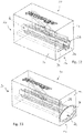
- the housing 12 of the mounting device has rounded edges 88, in particular in the transition between the input side 16 and connecting surfaces 90 and the output side 20 and the connecting surfaces 90, cf. FIGS. 10 and 11 ,
- the structure and operation of the mounting device 10 correspond to FIG FIGS. 10 and 11 the structure and operation of the mounting device according to FIGS. 1 to 9 , It is therefore referred to the above description.
- the mounting device according to FIG. 12 differs from the mounting device 10 according to FIGS. 1 to 9 in that the insertion profile 28 is closed on the circumference, ie the side wall 32 has no insertion profile opening 30 (cf. FIG. 1 ). This means that a section 94 of the insertion region 26 is closed in the direction of the side wall 32, thus providing an insertion profile 28 closed overall on the circumference.
- the circumferentially closed insertion profile 28 is as above with reference to FIGS. 1 to 9 described, in a profiled strip execution area 66 via, which is also circumferentially closed on the output side 20.
- FIG. 12 illustrated embodiment of a mounting device 10 with a circumferentially closed insertion profile 28 is used for a strip assembly 18, which is not (yet) connected to a window 36.
- the attachment portion 42 (see. FIG. 4 ) of the profile strip 22 in the section 94.
- a mounting device 10 according to FIG. 13 has an insertion portion 26 with a funnel-shaped insertion section 96, which extends from the input side 16 into the housing 12 of the mounting device 10 into the insertion profile 28 which is complementary to the cross section of the strip assembly 18 is formed.
- Mounting device 10 shown has a multi-part housing 12 with a first housing part 100 and with a second housing part 102.
- the housing parts 100 and 102 are rigidly connected to each other, for example glued together. But it is possible that the mounting device 10 described below has a one-piece housing 12 only.
- a first housing part 100 of the mounting device 10 according to FIGS. 14 to 19 extends between an input side 16 and an output side 20 along a main axis 14.
- the housing part 100 has an insertion region 26 and a separation region 46.
- a lifting device 48 of the separating region 46 is formed by a material section 104 of the housing part 100, but may additionally or alternatively also be formed by an additional element 50.
- the material section 104 also has a ramp section 56.
- first housing part 100 In the first housing part 100 are, comparable to the mounting device 10 according to FIGS. 1 to 9 , a mold ledge-out portion 66, and a carry-ledge lead-out portion 72 which open on the exit side 20 of the first case 100. There, these areas go into guide channels 106 for the profile strip 22 and 108 for the transport protection strip 24.
- the guide channels 106, 108 are arranged in the second housing part 102.
- a distance between the output side 20 of the first housing part 100 and a thereto adjacent input side of the second housing part 102 may be present.
- the guide channels 106, 108 have funnel-shaped insertion regions.
- the guide channels 106, 108 of the second housing part 102 open into a merging region 110, which serves to reconnect previously separate sections of the transport protection strip 24 and the profile strip 22.
- an indenting portion 112 is provided in the merge area, which cooperates with an upper side of the transport protection strip 24 and pushes the transport protection strip 24 from its upper side into the receiving area 40 of the profile strip 22, cf.
- FIG. 19
- the merging region 110 adjoins an output side 113 of the second housing part 102 facing away from the first housing part 100.
- the pressing portion 112 is an integral part of the housing material of the second housing part 102 and merges seamlessly into the upper boundary of the guide channel 108.
- the indenting section 112 may also be formed by a separate additional element (not shown), for example a metallic indentation block or an indenting roller.
- FIGS. 16 to 19 It is shown how a free end 76 of a last assembly 18 is inserted into the insertion area 26 (an initial state is in FIG FIG. 16 shown). Subsequently, a portion 86 of the transport protection strip 24 in above with reference to FIGS. 1 to 9 described manner separated from the profile strip 22 (see. FIG. 17 ).
- first guide path 116 is largely rectilinear, while the second guide path 114 a has a curved course and thus overall longer than the first guide 116.
- the length dimension 118 between free ends of the transport protection strip 24 and the profile strip 22 corresponds to the difference between the lengths of the guide paths 114 and 116.
Landscapes
- Engineering & Computer Science (AREA)
- Mechanical Engineering (AREA)
- Automobile Manufacture Line, Endless Track Vehicle, Trailer (AREA)
- Seal Device For Vehicle (AREA)
Description
Die Erfindung betrifft eine Montagevorrichtung mit den Merkmalen des Oberbegriffs des Patentanspruch 1.The invention relates to a mounting device with the features of the preamble of claim 1.
Aus dem Stand der Technik, beispielsweise aus der
Die Profilleiste wird nach ihrer Herstellung mit dem Randbereich der Windschutzscheibe verbunden, üblicherweise verklebt. Dieser Montageschritt wird üblicherweise bei Zulieferern durchgeführt, sodass die Zulieferer einem Kraftfahrzeughersteller eine Baugruppe liefern können, welche die Windschutzscheibe und die mit der Windschutzscheibe verbundene Profilleiste umfasst. Diese Baugruppe wird dann im Rahmen einer Endmontage eines Kraftfahrzeugs mit einer Windschutzscheibenaufnahme einer Kraftfahrzeugkarosserie verbunden; außerdem wird das angrenzende Kraftfahrzeugbauteil mit der Profilleiste gefügt.The profile strip is connected after its preparation with the edge region of the windshield, usually glued. This assembly step is typically performed at suppliers so that the suppliers can provide an assembly to an automotive manufacturer that includes the windshield and the trim associated with the windshield. This assembly is then connected as part of a final assembly of a motor vehicle with a windshield receptacle of a motor vehicle body; In addition, the adjacent vehicle component is joined to the profile strip.
Während des Transports der vorstehend genannten Baugruppe von dem Zulieferer zu dem Kraftfahrzeughersteller steht der zur Verbindung mit dem angrenzenden Bauteil vorgesehene Verbindungsabschnitt der Profilleiste von der Windschutzscheibe ab und ist somit mechanischen Einflüssen ausgesetzt. Gleichzeitig ist es aber erwünscht, dass die Baugruppe platzsparend und "stehend" transportiert werden kann, dass also die Windschutzscheibe hochkant transportiert werden kann. Außerdem ist es erwünscht, dass die Windschutzscheibe während des Transports gegen eine Beschädigung des unteren Randbereichs geschützt ist. Ein solcher Schutz ist dadurch gewährleistet, dass sich die Windschutzscheibe während ihres Transports auf dem Verbindungsabschnitt der Profilleiste abstützt. Dies bedeutet aber, dass das Gewicht der Windschutzscheibe während des Transports der Baugruppe auf dem Verbindungsabschnitt der Profilleiste lastet. Diese Belastung bewirkt eine unerwünschte Verformung (Stauchung) des den Aufnahmebereich begrenzenden Verbindungsabschnitts der Profilleiste.During the transport of the aforementioned assembly from the supplier to the motor vehicle manufacturer, the connecting portion of the profiled strip intended for connection to the adjacent component is of the Windscreen off and is thus exposed to mechanical influences. At the same time, it is desirable that the assembly can be transported to save space and "standing", so that the windshield can be transported upright. In addition, it is desirable that the windshield is protected during transport against damage to the lower edge region. Such protection is ensured by the fact that the windshield is supported during its transport on the connecting portion of the profile strip. However, this means that the weight of the windshield weighs during transport of the assembly on the connecting portion of the profile strip. This load causes an undesirable deformation (compression) of the receiving portion limiting connecting portion of the profile strip.
Zur Vermeidung einer Verformung einer mit einer Windschutzscheibe verbundenen Profilleiste ist es aus dem Stand der Technik (beispielsweise aus der
Nach Anlieferung der Baugruppe "Windschutzscheibe und Profilleiste" bei dem Kraftfahrzeughersteller wird die Transportschutzleiste wieder aus dem Aufnahmebereich der Profilleiste entfernt, damit der Verbindungsabschnitt mit dem angrenzenden Kraftfahrzeugbauteil, insbesondere mit der Wasserkastenabdeckung, verbunden werden kann. Die Transportschutzleiste wird anschließend entsorgt.After delivery of the assembly "windshield and profile strip" at the motor vehicle manufacturer, the transport protection strip is removed again from the receiving area of the profile strip, so that the connecting portion with the adjacent vehicle component, in particular with the water box cover, can be connected. The transport protection strip is then disposed of.
Zur Entfernung der Transportschutzleiste aus dem Aufnahmebereich des Verbindungsabschnitts der Profilleiste schlägt die
Die vorstehend genannten, zusätzlichen Handhabungsabschnitte vereinfachen die Entfernung der Transportschutzleiste aus dem Aufnahmebereich der Profilleiste. Die Transportschutzleiste und die Handhabungsabschnitte müssen aber zunächst als Einzelteile hergestellt werden und dann vom Zulieferer an der Profilleiste montiert werden. Nach dem Transport der Baugruppe zu dem Kraftfahrzeughersteller muss der Kraftfahrzeughersteller die Transportschutzleiste und die Handhabungsabschnitte dann wieder demontieren. Schließlich müssen die Transportschutzleiste und die Handhabungsabschnitte gesammelt und entsorgt werden.The above-mentioned additional handling sections simplify the removal of the transport protection strip from the receiving area of the profile strip. However, the transport protection strip and the handling sections must first be manufactured as individual parts and then be mounted by the supplier on the profile strip. After the assembly has been transported to the motor vehicle manufacturer, the motor vehicle manufacturer must then dismantle the transport protection strip and the handling sections again. Finally, the transport protection strip and the handling sections must be collected and disposed of.
Aus der
Aus der
Aus der
Ausgehend von der
Diese Aufgabe wird bei einer Montagevorrichtung mit den Merkmalen des Oberbegriffs des Patentanspruchs 1 erfindungsgemäß durch eine Montagevorrichtung mit den kennzeichnenden Merkmalen des Patentanspruchs 1 gelöst.This object is achieved in a mounting device with the features of the preamble of claim 1 according to the invention by a mounting device with the characterizing features of claim 1.
Die erfindungsgemäße Montagevorrichtung weist zwei wesentliche Bereiche auf. Der Einführbereich dient dazu, das freie Ende der Leistenanordnung in die Montagevorrichtung einzuführen. Somit wird eine Relativpositionierung zwischen dem freien Ende der Leistenanordnung und dem Trennbereich, der zum Trennen der Transportschutzleiste von der Profilleiste ausgebildet ist, ermöglicht.The mounting device according to the invention has two essential areas. The insertion area serves to introduce the free end of the strip assembly in the mounting device. Thus, a relative positioning between the free end of the strip assembly and the separation area, which is designed to separate the transport protection strip from the profile strip, allows.
Die erfindungsgemäße Montagevorrichtung hat den Vorteil, dass (aus dem Stand der Technik bekannte) separate, an der Transportschutzleiste zu befestigende Handhabungsabschnitte entfallen können.The mounting device according to the invention has the advantage that (known from the prior art) can be omitted separate, to be attached to the transport protection strip handling sections.
Die erfindungsgemäße Montagevorrichtung ist für eine Vielzahl von Leistenanordnungen wiederverwendbar. Nach Einführen des freien Endes der Leistenanordnung in den Einführbereich und Trennen der Transportschutzleiste von der Profilleiste kann die Montagevorrichtung wieder von den zumindest abschnittweise getrennten Bauteilen "Transportschutzleiste und Profilleiste" entfernt und für eine weitere Leistenanordnung verwendet werden. Die Montagevorrichtung kann also stationär in einer Fertigungsumgebung eines Zulieferers oder eines Kraftfahrzeugherstellers vorgehalten werden und muss nicht gemeinsam mit Fahrzeugscheiben und Leistenanordnungen "mittransportiert" werden.The mounting device according to the invention is reusable for a variety of strip assemblies. After insertion of the free end of the strip assembly in the insertion and separating the transport protection strip from the profile strip, the mounting device can again from the at least sections removed components "transport protection strip and profile strip" and used for a further strip arrangement. The mounting device can thus be kept stationary in a manufacturing environment of a supplier or a motor vehicle manufacturer and does not have to be "transported along" with vehicle windows and strip assemblies.
Es ist bevorzugt, dass der Einführbereich ein zu dem Querschnitt der Leistenanordnung zumindest abschnittsweise komplementäres Einführprofil aufweist. Insbesondere ist die Leistenanordnung bezogen auf eine Längsachse der Leistenanordnung nur in einer Drehlage in den Einführbereich der Leistenanordnung einführbar.It is preferred that the insertion region has an insertion profile which is at least partially complementary to the cross section of the strip arrangement. In particular, the strip arrangement is insertable relative to a longitudinal axis of the strip arrangement only in a rotational position in the insertion region of the strip arrangement.
Bei einer Ausführungsform der Erfindung ist das Einführprofil umfangsseitig geschlossen. Dies bedeutet, dass ein in den Einführbereich eingeführtes freies Ende der Leistenanordnung entlang seines kompletten Umfangs von Führungsabschnitten des Einführprofils umschlossen ist. Ein solches, in Umfangsrichtung geschlossenes Einführprofil ermöglicht eine besonders zuverlässige Relativpositionierung der Leistenanordnung und des Trennbereichs der Montagevorrichtung.In one embodiment of the invention, the insertion is closed circumferentially. This means that an inserted into the insertion free end of the strip assembly is enclosed along its entire circumference of guide portions of the Einführprofils. Such, in the circumferential direction closed insertion allows a particularly reliable relative positioning of the strip assembly and the separation region of the mounting device.
Bei einer alternativen Ausführungsform weist das Einführprofil eine Einführprofilöffnung auf, in welcher ein Randbereich einer Fensterscheibe anordenbar ist. Diese Ausführung hat den Vorteil, dass die Montagevorrichtung auch dann verwendet werden kann, um eine Transportschutzleiste von der Profilleiste zu trennen, wenn die Profilleiste bereits an einer Fensterscheibe befestigt ist.In an alternative embodiment, the insertion profile has an insertion profile opening, in which an edge region of a window pane can be arranged. This embodiment has the advantage that the mounting device can also be used to separate a transport protection strip from the profile strip when the profile strip is already attached to a window pane.
Das Einführprofil ist vorzugsweise durch Wandabschnitte eines Gehäuses der Montagevorrichtung begrenzt. Ein solches Gehäuse kann beispielsweise aus einem Kunststoffmaterial hergestellt sein. Das Gehäuse kann Außenabmessungen aufweisen, die es ermöglichen, die Montagevorrichtung von Hand zu führen und als Handwerkzeug zu verwenden. Das Gehäuse kann zusätzlich oder alternativ hierzu auch Teil einer maschinellen Fertigungseinrichtung sein.The insertion profile is preferably limited by wall sections of a housing of the mounting device. Such a housing may for example be made of a plastic material. The housing may have outer dimensions that allow to guide the mounting device by hand and as To use hand tools. The housing may additionally or alternatively be part of a mechanical manufacturing facility.
Das Einführprofil kann zumindest abschnittsweise durch reibungsmindernde Führungs- und/oder Antriebsabschnitte begrenzt sein. Beispielsweise können nicht angetriebene Laufrollen und/oder Antriebsrollen verwendet werden, die mit einer der Leistenanordnung zugewandten Lauffläche oder Antriebsfläche das Einführprofil mitbegrenzen.The introduction profile can be limited at least in sections by friction-reducing guide and / or drive sections. For example, non-driven rollers and / or drive rollers can be used, which mitbegrenzen with one of the strip assembly facing tread or drive surface, the insertion.
Im Rahmen der Erfindung wird weiter vorgeschlagen, dass der Trennbereich eine Hebeeinrichtung mit einem Rampenabschnitt aufweist, der die Transportschutzleiste zumindest abschnittsweise untergreift und aus dem Aufnahmebereich der Profilleiste heraushebt. Ein solcher Rampenabschnitt hat den Vorteil, dass die zunächst noch in dem Aufnahmebereich der Profilleiste angeordnete Transportschutzleiste entlang ihrer Länge über den Rampenabschnitt gleiten kann und die Transportschutzleiste somit schonend, einfach und mit niedrigen Montagekräften von der Profilleiste abgelöst werden kann.In the context of the invention, it is further proposed that the separation area has a lifting device with a ramp section which engages under the transport protection strip at least in sections and lifts it out of the receiving area of the profile strip. Such a ramp section has the advantage that the transport protection strip initially arranged in the receiving area of the profile strip can slide over the ramp section along its length and the transport protection strip can thus be detached from the profile strip gently, simply and with low assembly forces.
Der Rampenabschnitt kann beispielsweise durch einen Abschnitt eines oder des Gehäuses der Montagevorrichtung gebildet sein, wodurch eine besonders einfache und preisgünstige Montagevorrichtung geschaffen wird. Der Rampenabschnitt kann zusätzlich oder alternativ hierzu auch durch ein insbesondere klingenförmiges Zusatzelement gebildet sein. Ein solches Zusatzelement ist beispielsweise aus einem metallischen Material hergestellt und mit dem Gehäuse der Montagevorrichtung verbunden. Es ist möglich, die Verbindung zwischen Zusatzelement und Gehäuse dauerhaft und unlösbar auszubilden, beispielsweise indem ein metallisches Zusatzelement mit Kunststoffmaterial umformt wird. Es ist aber auch möglich, das Zusatzelement lösbar mit einem Gehäuse der Montagevorrichtung zu verbinden, um nach einem etwaigen Verschleiß des Zusatzelements ein Austauschzusatzelement an der Montagevorrichtung zu befestigen.The ramp portion may be formed, for example, by a portion of or the housing of the mounting device, whereby a particularly simple and inexpensive mounting device is provided. The ramp section may additionally or alternatively be formed by a particular blade-shaped additional element. Such an additional element is made for example of a metallic material and connected to the housing of the mounting device. It is possible to permanently and permanently form the connection between the additional element and the housing, for example by forming a metallic additional element with plastic material. But it is also possible to releasably connect the additional element with a housing of the mounting device to after any Wear of the additional element to attach a replacement additional element to the mounting device.
Ferner ist es bevorzugt, wenn die Montagevorrichtung einen Profilleisten-Ausführbereich und/oder einen Transportschutzleisten-Ausführbereich aufweist. Diese Führungsbereiche dienen dazu, bereits voneinander getrennte Abschnitte der Profilleiste bzw. der Transportschutzleiste so zu führen, dass die Profilleiste und/oder die Transportschutzleiste relativ zu der Montagevorrichtung eine definierte räumliche Lage einnehmen, um die weitere Handhabung der Leistenanordnung bzw. der voneinander getrennten Teile der Leistenanordnung zu vereinfachen.Furthermore, it is preferred if the mounting device has a profiled strip execution area and / or a transport protection strip execution area. These guide areas serve to lead already separated sections of the profile strip or the transport protection strip so that the profile strip and / or the transport protection strip occupy a defined spatial position relative to the mounting device to further handling the strip assembly or the separate parts of the To simplify bar arrangement.
Im Rahmen der Erfindung ist es möglich, dass der Profilleisten-Ausführbereich und/oder der Transportschutzleisten-Ausführbereich endseitig offen ist oder sind. Dies ermöglicht es, die Montagevorrichtung entlang der gesamten Länge der Leistenanordnung an der Leistenanordnung anzuwenden, um auf diese Weise die Transportschutzleiste entlang ihrer gesamten Länge von der Profilleiste abzutrennen.Within the scope of the invention, it is possible for the profile strip execution area and / or the transport protection strip execution area to be open at the end. This makes it possible to apply the mounting device along the entire length of the strip assembly on the strip assembly, in order to separate in this way the transport protection strip along its entire length from the profile strip.
Es ist auch möglich, dass der Profilleisten-Ausführbereich und/oder der Transportschutzleisten-Ausführbereich endseitig geschlossen ist oder sind. Auf diese Weise ist es möglich, eine Transportschutzleiste im Bereich eines freien Endes der Leistenanordnung von der Profilleiste abzutrennen, bis das freie Ende der Profilleiste und/oder das freie Ende der Transportschutzleiste in Anlage mit einem endseitigen Verschluss eines Ausführbereichs gelangt. Anschließend kann die Montagevorrichtung (in entgegengesetzter Richtung) wieder entfernt werden und die Transportschutzleiste dadurch von der Profilleiste vollständig abgetrennt werden, dass die Transportschutzleiste im Bereich ihres von der Profilleiste bereits abgetrennten Abschnitts manuell oder maschinell ergriffen und auch entlang der verbleibenden Länge von der Profilleiste abgetrennt wird.It is also possible that the profile strip execution area and / or the transport protection strip execution area is or are closed at the end. In this way it is possible to separate a transport protection strip in the region of a free end of the strip assembly of the profile strip until the free end of the profile strip and / or the free end of the transport protection strip comes into contact with an end closure of a Ausführbereichs. Subsequently, the mounting device (in the opposite direction) can be removed and the transport protection strip are thereby completely separated from the profile strip that the transport protection strip in the region of their already separated from the profile strip section manually or mechanically seized and also separated along the remaining length of the profile strip ,
Bei einer besonders bevorzugten Ausführungsform der Erfindung weist die Montagevorrichtung einen Zusammenführungsbereich zum Zusammenführen eines von dem Aufnahmebereich von der Profilleiste getrennten Abschnitts der Transportschutzleiste und der Profilleiste auf. Ein solcher Zusammenführungsbereich ermöglicht es, einen bereits von der Profilleiste abgetrennten Abschnitt der Transportschutzleiste wieder mit dem Aufnahmebereich der Profilleiste zu verbinden.In a particularly preferred embodiment of the invention, the mounting device on a merge area for merging a separate from the receiving area of the profile strip portion of the transport protection strip and the profile strip. Such a merging region makes it possible to reconnect a section of the transport protection strip already cut off from the profile strip to the receiving region of the profile strip.
Zu diesem Zweck kann beispielsweise ein Eindrückabschnitt vorgesehen sein, der die Transportschutzleiste zumindest mit einem Teilbereich ihres Querschnitts in den Aufnahmebereich der Profilleiste hineindrückt.For this purpose, for example, an indenting section can be provided which presses the transport protection strip into the receiving area of the profile strip at least with a partial area of its cross section.
Der Eindrückabschnitt kann durch einen Abschnitt des Gehäuses der Montagevorrichtung und/oder durch ein insbesondere block-oder rollenförmiges Zusatzelement gebildet sein.The indenting portion may be formed by a portion of the housing of the mounting device and / or by a particular block or roller-shaped additional element.
Die Vorteile des Zusammenführens von Transportschutzleiste und Profilleiste werden weiter unten unter Bezugnahme auf erfindungsgemäße Verfahren erläutert.The advantages of merging the transport protection strip and profile strip are explained below with reference to the inventive method.
Im Rahmen der Erfindung ist es möglich, dass die Montagevorrichtung ein einteiliges Gehäuse aufweist, welches besonders einfach handhabbar ist.In the context of the invention, it is possible that the mounting device has a one-piece housing, which is particularly easy to handle.
Die Montagevorrichtung kann auch ein mehrteiliges Gehäuse aufweisen, wobei das Gehäuse ein erstes Gehäuseteil umfasst, das zumindest den Einführbereich und den Trennbereich aufweist und ein zweites Gehäuseteil, welches zumindest einen vorstehend genannten Zusammenführungsbereich aufweist. Ein solcher mehrteiliger Gehäuseaufbau ermöglicht es, die beiden Funktionen "Trennen" und "Zusammenführen" von Profilleiste und Transportschutzleiste räumlich voneinander getrennt und in Längsrichtung der Leistenanordnung zueinander versetzt vorzuhalten.The mounting device can also have a multi-part housing, wherein the housing comprises a first housing part which has at least the insertion region and the separation region and a second housing part which has at least one aforementioned merging region. Such a multi-part housing structure makes it possible to spatially separate the two functions "separating" and "merging" of the profile strip and the transport protection strip and to stagger each other in the longitudinal direction of the strip arrangement.
Es ist möglich, dass die Gehäuseteile starr oder bewegbar miteinander verbunden sind. Eine starre Verbindung ermöglicht es, die Montagevorrichtung so zu handhaben, als wenn sie einteilig wäre. Wenn die Gehäuseteile bewegbar miteinander verbunden sind, ist besonders vorteilhaft, dass die Gehäuseteile bei Bewegung der Montagevorrichtung längs einer Leistenanordnung einer Krümmung der Leistenanordnung folgen können. Eine solche Krümmung kann vorgesehen sein, wenn die Profilleiste der Krümmung eines unteren Randbereichs einer Windschutzscheibe folgend einen entsprechend gekrümmten Verlauf aufweist.It is possible that the housing parts are rigidly or movably connected to each other. A rigid connection makes it possible to handle the mounting device as if it were in one piece. When the housing parts are movably connected to one another, it is particularly advantageous that the housing parts can follow a curvature of the strip arrangement along a strip arrangement when the mounting device moves. Such a curvature can be provided if the profile strip following the curvature of a lower edge region of a windshield has a correspondingly curved course.
Insbesondere für den Fall von bewegbar miteinander verbundenen Gehäuseteilen (aber auch für den Fall von starr miteinander verbundene Gehäuseteilen) kann ein Abstand zwischen der Ausgangsseite des ersten Gehäuseteils und einer hierzu benachbarten Eingangsseite des zweiten Gehäuseteils vorhanden sein. Dies bedeutet, dass auch ein Ausgang des Profilleisten-Ausführbereichs an dem ersten Gehäuseteil und ein Eingang eines in dem zweiten Gehäuseteil vorgesehenen Führungskanals für die Profilleiste sowie ein Ausgang des Transportschutzleisten-Ausführbereichs an dem ersten Gehäuseteil und ein Eingang eines in dem zweiten Gehäuseteil vorgesehenen Führungskanals für die Transportschutzleiste zueinander beabstandet sind. In diesem Fall ist es vorteilhaft, wenn die Führungskanäle an der Eingangsseite des zweiten Gehäuseteils trichterförmige Einführbereiche aufweisen.In particular, in the case of movably connected housing parts (but also in the case of rigidly interconnected housing parts), a distance between the output side of the first housing part and an adjacent thereto input side of the second housing part may be present. This means that there is also an exit of the profiled strip delivery area on the first housing part and an entrance of a guide channel provided in the second housing part for the profiled strip and an exit of the transport protection strip execution area on the first housing part and an entrance of a guide channel provided in the second housing part the transport protection strip are spaced from each other. In this case, it is advantageous if the guide channels on the input side of the second housing part have funnel-shaped insertion regions.
Im Rahmen der Erfindung ist es möglich, dass die Montagevorrichtung manuell gehandhabt wird und mit Handkraft entlang zumindest eines Teils der Längserstreckung der Leistenanordnung bewegt wird und/oder dass eine Leistenanordnung von Hand durch die Montagevorrichtung (manuell gehalten oder an einem Träger befestigt) hindurchbewegt wird.In the context of the invention, it is possible that the mounting device is handled manually and is moved by hand force along at least part of the longitudinal extent of the strip assembly and / or that a strip assembly by hand by the mounting device (manually held or attached to a support) is moved through.
Es ist auch möglich, dass eine Antriebseinrichtung vorgesehen ist, die eine längs der Leistenanordnung gerichtete Relativbewegung zwischen einer Leistenanordnung und der Montagevorrichtung erzeugt. Dabei ist es möglich, die Montagevorrichtung längs einer feststehenden Leistenanordnung zu bewegen. Es ist auch möglich, die Leistenanordnung längs einer feststehenden Montagevorrichtung anzutreiben. Ferner können die vorstehend genannten Antriebsmöglichkeiten auch miteinander kombiniert werden.It is also possible for a drive device to be provided which generates a relative movement directed along the strip arrangement between a strip arrangement and the mounting device. It is possible to move the mounting device along a fixed strip assembly. It is also possible to drive the strip assembly along a fixed mounting device. Furthermore, the aforementioned drive options can also be combined with each other.
Die Erfindung betrifft ferner ein Verfahren gemäß Patentanspruch 17.The invention further relates to a method according to claim 17.
Vorteile und Ausgestaltungen des erfindungsgemäßen Verfahrens wurden zum Teil bereits vorstehend unter Bezugnahme auf die erfindungsgemäße Montagevorrichtung beschrieben. Auf diese vorstehende Beschreibung wird daher Bezug genommen. Zusätzlich werden nachstehend weitere Vorteile und Ausgestaltungen des erfindungsgemäßen Verfahrens beschrieben.Advantages and embodiments of the method according to the invention have in part already been described above with reference to the mounting device according to the invention. Reference is therefore made to this description above. In addition, further advantages and embodiments of the method according to the invention are described below.
Bei einem besonders bevorzugten Verfahren wird eine Montagevorrichtung verwendet, die einen Zusammenführungsbereich zum Zusammenführen von Transportschutzleiste und Profilleiste umfasst. Bei diesem Verfahren wird die Profilleiste entlang eines ersten Führungswegs geführt, der eine erste Länge aufweist. Ferner wird ein von der Profilleiste getrennter Abschnitt der Transportschutzleiste entlang eines zweiten Führungswegs geführt, der eine von der ersten Länge verschiedene zweite Länge aufweist. Außerdem werden im Ausgangszustand miteinander verbundene und dann voneinander getrennte Abschnitte der Transportschutzleiste und der Profilleiste wieder zusammengeführt, und die Transportschutzleiste wird in den Aufnahmebereich der Profilleiste eingedrückt. Dieses Verfahren ermöglicht es, einen bestimmten Ausgangszustand einer Leistenanordnung mit einer bestimmten Relativpositionierung von Transportschutzleiste und Profilleiste (bezogen auf die Längserstreckung der Leistenanordnung), zu ändern, und zwar dadurch, dass die Führungswege für die Profilleiste und für die Transportschutzleiste unterschiedlich lang sind. Ein Zusammenführen von voneinander getrennten Abschnitten von Transportschutzleiste und Profilleiste nach Durchlauf unterschiedlich langer Führungswege führt dazu, dass der genannte Ausgangszustand so verändert wird, dass ein bestimmter Abschnitt der Transportschutzleiste in Längsrichtung der Leistenanordnung gesehen und bezogen auf den Ausgangszustand in einer veränderten Position wieder mit der Profilleiste gefügt wird. Auf diese Weise ist es möglich, ausgehend von einem Ausgangszustand der Leistenanordnung die Transportschutzleiste relativ zu der Profilleiste in Längsrichtung um ein bestimmtes Längenmaß zu versetzen.In a particularly preferred method, a mounting device is used which comprises a merging area for merging the transport protection strip and profile strip. In this method, the profiled strip is guided along a first guide path having a first length. Furthermore, a section of the transport protection strip separated from the profile strip is guided along a second guide path which has a second length which is different from the first length. In addition, in the initial state interconnected and then separate sections of the transport guard and the profile strip are brought together again, and the transport protection strip is pressed into the receiving area of the profile strip. This method makes it possible to change a certain initial state of a strip arrangement with a certain relative positioning of the transport protection strip and profile strip (based on the longitudinal extent of the strip arrangement), in that the guide paths for the profile strip and for the transport protection strip are of different lengths. Merging of separate sections of transport protection strip and profile strip after passing different lengths of guide leads to the fact that the initial state is changed so that a certain portion of the transport protection strip seen in the longitudinal direction of the strip assembly and based on the initial state in an altered position again with the profile strip is added. In this way, it is possible, starting from an initial state of the strip assembly to put the transport protection strip relative to the profile strip in the longitudinal direction by a certain length.
Es ist insbesondere bevorzugt, dass die zweite Länge (entspricht dem Führungsweg der Transportschutzleiste) größer ist als die erste Länge (entspricht dem Führungsweg der Profilleiste). Auf diese Weise ist es möglich, die im Verhältnis zu der Transportschutzleiste üblicherweise formstabilere Profilleiste entlang eines kürzeren Führungswegs zu führen und die üblicherweise weniger stabile und daher biegsamere Transportschutzleiste entlang des zweiten, längeren Führungswegs zu führen.It is particularly preferred that the second length (corresponding to the guide path of the transport protection strip) is greater than the first length (corresponds to the guide path of the profile strip). In this way it is possible that in relation to the transport protection bar usually dimensionally stable profile strip to lead along a shorter guide path and to lead the usually less stable and therefore more flexible transport protection strip along the second, longer guide path.
Ein längerer Führungsweg kann insbesondere im Verhältnis zu einem kürzeren Führungsweg eine stärkere Krümmung aufweisen. Im Idealfall ist der kürzere Führungsweg weitestgehend geradlinig oder aber weist lediglich eine Krümmung auf, die der Krümmung eines unteren Randbereichs einer angrenzenden Windschutzscheibe entspricht. Diese Krümmung verläuft parallel zu einer Ebene einer Fensterscheibe, an der die Profilleiste angeordnet oder anordenbar ist; die "stärkere Krümmung" des längeren Führungsweg verläuft vorzugsweise in einer zu der Ebene der Fensterscheibe geneigten oder senkrechten Richtung.A longer guide path can have a greater curvature, in particular in relation to a shorter guide path. Ideally, the shorter guide path is largely straight or has only a curvature corresponding to the curvature of a lower edge region of an adjacent windshield. This curvature runs parallel to a plane of a window pane on which the profile strip is arranged or can be arranged; the "greater curvature" of the longer guide path preferably runs in a direction inclined or perpendicular to the plane of the window pane.
Besondere Vorteile ergeben sich, wenn die Leistenanordnung, die in den Einführbereich eingeführt wird, zueinander bündige Enden der Profilleiste und der Transportschutzleiste aufweist, und wenn diese Enden nach dem Eindrücken zumindest eines Teilbereichs des Querschnitts der Transportschutzleiste in den Aufnahmebereich der Profilleiste um ein Längenmaß versetzt sind, dass der Differenz der Längen der Führungswege entspricht.Particular advantages arise when the strip assembly, which is inserted into the insertion, has mutually flush ends of the profile strip and the transport protection strip, and if these ends are offset after pressing at least a portion of the cross section of the transport protection strip in the receiving area of the profile strip by a Längenmaß in that the difference corresponds to the lengths of the guide ways.
Dies ermöglicht es, eine Leistenanordnung vorzusehen, welche zunächst miteinander bündige freie Enden aufweist. Ein solches bündiges Ende kann beispielsweise dadurch hergestellt werden, dass Profilleiste und Transportschutzleiste jeweils in einem Endlosverfahren (beispielsweise durch Extrusion) hergestellt und miteinander gefügt werden. Anschließend können diese Endlos-Leistenanordnungen beispielsweise mittels eines Schneidwerkzeugs so abgelängt werden, dass vereinzelte Leistenanordnungen entstehen, deren Längen der Länge eines unteren Randbereichs einer Windschutzscheibe entsprechen. Wenn nun eine solche vereinzelte Leistenanordnung wie vorstehend beschrieben so bearbeitet wird, dass die Transportschutzleiste zunächst abschnittsweise von der Profilleiste entfernt und anschließend voneinander getrennte Abschnitte wieder zusammengeführt werden, wobei sich die Länge der Führungswege von Profilleiste und Transportschutzleiste unterscheiden, wird aus der zueinander bündigen Anordnung der Enden von Profilleiste und Transportschutzleiste eine versetzte Anordnung der Enden von Profilleiste und Transportschutzleiste erzeugt, wobei das Längenmaß des Versatzes der freien Enden von Profilleiste und Transportschutzleiste der Differenz der Längen der Führungswege entspricht.This makes it possible to provide a strip arrangement which initially has mutually flush free ends. Such a flush end can be produced, for example, by producing the profile strip and the transport protection strip in each case in a continuous process (for example by extrusion) and joining them together. Subsequently, these endless strip arrangements can be cut to length, for example by means of a cutting tool, so that isolated strip arrangements arise whose lengths correspond to the length of a lower edge region of a windshield. If now such an isolated strip arrangement as described above is processed so that the transport protection strip initially sections of the profile strip removed and then separated sections are merged again, with the length of the guide rails differ from the profile strip and transport protection strip, a staggered arrangement of the ends of the profile strip and transport protection strip is generated from the mutually flush arrangement of the ends of the profile strip and transport protection strip wherein the length dimension of the offset of the free ends of the profile strip and the transport protection strip corresponds to the difference in the lengths of the guide paths.
Beispielsweise ist es möglich, eine vereinzelte Leistenanordnung mit einer Profilleiste und einer daran befestigten Transportschutzleiste zu bearbeiten, wobei an beiden freien und voneinander abgewandten Enden der Leistenanordnung die jeweiligen Stirnflächen der Profilleiste und der Transportschutzleiste miteinander bündig sind. Nach Durchlauf des vorstehend erörterten Verfahrens und Anwendung der Montagevorrichtung entlang der gesamten Länge einer solchen Leistenanordnung ist die Stirnfläche eines ersten freien Endes der Transportschutzleiste in Längsrichtung der Leistenanordnung gesehen weiter in die Profilleiste hineinversetzt; das entgegengesetzte zweite freie Ende der Transportschutzleiste jedoch steht in Längsrichtung der Leistenanordnung gesehen über die benachbarte Stirnfläche der Profilleiste hervor. Eine solche Anordnung ermöglicht es immer noch, eine ausreichende Transportschutzwirkung bereitzustellen. Zu dem Zeitpunkt aber, zu dem die Transportschutzleiste von der Profilleiste entfernt werden soll, kann die Transportschutzleiste an ihrem freien Ende, welches über eines der freien Enden der Profilleiste hervorsteht, manuell oder maschinell ergriffen und durch einfaches Ziehen oder Anheben der Transportschutzleiste von der Profilleiste vollständig abgetrennt werden.For example, it is possible to process an isolated strip arrangement with a profile strip and a transport protection strip attached thereto, wherein the respective end faces of the profile strip and the transport protection strip are flush with each other at both free and mutually remote ends of the strip arrangement. After passing through the method discussed above and using the mounting device along the entire length of such a strip arrangement, the end face of a first free end of the transport strip is placed further into the profile strip in the longitudinal direction of the strip arrangement; However, the opposite second free end of the transport protection strip is seen in the longitudinal direction of the strip assembly seen on the adjacent end face of the profile strip. Such an arrangement still makes it possible to provide a sufficient transport protection effect. At the time but to which the transport protection strip is to be removed from the profile strip, the transport protection strip at its free end, which protrudes beyond one of the free ends of the profile strip, manually or mechanically grasped and completely by simply pulling or lifting the transport protection strip of the profile strip be separated.
Das vorstehend erörterte Verfahren kann auch für vereinzelte Leistenanordnungen angewendet werden, bei denen die freien Enden der Profilleisten und der Transportschutzleiste nicht miteinander bündig sind, bei der also relativ zueinander um ein erstes Längenmaß versetzte Enden der Profilleiste und der Transportschutzleiste vorgesehen sind. Diese Enden sind nach dem Eindrücken zumindest eines Teilbereichs des Querschnitts der Transportschutzleiste in den Aufnahmebereich der Profilleiste um ein von dem ersten Längenmaß verschiedenes zweites Längenmaß versetzt, wobei der Betrag der Differenz zwischen dem ersten Längenmaß und dem zweiten Längenmaß der Differenz der Längen der Führungswege entspricht.The method discussed above can also be used for isolated bar arrangements in which the free Ends of the profile strips and the transport protection strip are not flush with each other, in which therefore provided relative to each other by a first length measure offset ends of the profile strip and the transport protection strip. These ends are offset after pressing at least a portion of the cross section of the transport protection strip in the receiving area of the profile strip by a different from the first measure second Längenmaß, wherein the amount of difference between the first measure and the second Längenmaß the difference corresponds to the lengths of the guide ways.
Die vorstehend beschriebenen Verfahren eignen sich besonders gut zur Verwendung in unmittelbarem Anschluss an die Herstellung einer Leistenanordnung. Dies hat den Vorteil, dass ein Zulieferer, der die Profilleiste herstellt (und/oder eine Baugruppe, umfassend eine Fensterscheibe und eine daran befestigte Profilleiste), die Profilleiste und/oder die Baugruppe bereits für einen Transportschutz vorbereiten kann, aber so, dass im Rahmen der Endmontage der Baugruppe beim Kraftfahrzeughersteller die aus dem Stand der Technik bekannten Handhabungsabschnitte nicht benötigt werden. Es ist bei der Endmontage eines Kraftfahrzeugs dann auch nicht erforderlich, die erfindungsgemäße Montagevorrichtung zu verwenden, weil dieser Montageschritt bereits durch den Zulieferer durchgeführt werden kann.The methods described above are particularly well suited for use immediately following the manufacture of a last assembly. This has the advantage that a supplier who produces the profile strip (and / or an assembly comprising a window pane and a profile strip attached thereto) can already prepare the profile strip and / or the assembly for transport protection, but in such a way the final assembly of the assembly in the motor vehicle manufacturer, the handling sections known from the prior art are not needed. It is then not necessary in the final assembly of a motor vehicle to use the mounting device according to the invention, because this assembly step can already be performed by the supplier.
Demnach betrifft die Erfindung auch die Verwendung einer eingangs beschriebenen Montagevorrichtung zur Durchführung eines vorstehend beschriebenen Verfahrens.Accordingly, the invention also relates to the use of a mounting device described above for carrying out a method described above.
Weitere Merkmale und Vorteile der Erfindung sind Gegenstand der nachfolgenden Beschreibung und der zeichnerischen Darstellung bevorzugter Ausführungsbeispiele.Further features and advantages of the invention are the subject of the following description and the drawings of preferred embodiments.
In den Zeichnungen zeigen:
- Fig. 1
- eine perspektivische Darstellung einer Ausführungsform einer Montagevorrichtung;
- Fig. 2
- die Montagevorrichtung gemäß
Fig. 1 in einem Teilschnitt; - Fig. 3
- die Montagevorrichtung gemäß
Fig. 1 aus einer rückwärtigen Perspektive; - Fig. 4
- eine Anordnung mit der Montagevorrichtung gemäß
Fig. 1 und mit einer an einem Randbereich einer Fensterscheibe eines Kraftfahrzeugs angeordneten Leistenanordnung, vor dem Einführen eines freien Endes der Leistenanordnung in einen Einführbereich der Montagevorrichtung; - Fig. 5
- die Anordnung gemäß
Fig. 4 in einem Teilschnitt; - Fig. 6
- die Anordnung gemäß
Fig. 4 aus einer rückwärtigen Perspektive; - Fig. 7
- die Anordnung gemäß
Fig. 4 , nach dem Einführen des freien Endes der Leistenanordnung in den Einführbereich der Montagevorrichtung und nach dem Trennen des freien Endes der Transportschutzleiste von der Profilleiste in einem Trennbereich der Montagevorrichtung; - Fig. 8
- die Anordnung gemäß
Fig. 7 in einem Teilschnitt; - Fig. 9
- die Anordnung gemäß
Fig. 7 aus einer rückwärtigen Perspektive; - Fig. 10
- eine weitere Ausführungsform einer Montagevorrichtung;
- Fig. 11
- die Montagevorrichtung gemäß
Fig. 10 aus einer um ca. 120° verdrehten Perspektive; - Fig. 12
- eine weitere Ausführungsform einer Ausführungsform einer Montagevorrichtung, mit einem umfangsseitig geschlossenen Einführbereich;
- Fig. 13
- eine weitere Ausführungsform einer Ausführungsform einer Montagevorrichtung, mit einem umfangsseitig geschlossenen, trichterförmig ausgebildeten Einführbereich;
- Fig. 14
- eine weitere Ausführungsform einer Ausführungsform einer Montagevorrichtung, mit einem Zusammenführungsbereich zum Zusammenführen eines von einem Aufnahmebereich der Profilleiste getrennten Abschnitts der Transportschutzleiste und der Profilleiste;
- Fig. 15
- die Montagevorrichtung gemäß
Fig. 14 in einem Teilschnitt; - Fig. 16
- eine Anordnung mit der Montagevorrichtung gemäß
Fig. 14 und mit einer Leistenanordnung, vor dem Einführen eines freien Endes der Leistenanordnung in einen Einführbereich der Montagevorrichtung; - Fig. 17
- die Anordnung gemäß
Fig. 16 , nach dem Einführen des freien Endes der Leistenanordnung in den Einführbereich der Montagevorrichtung und nach dem Trennen des freien Endes der Transportschutzleiste von der Profilleiste in einem Trennbereich der Montagevorrichtung; - Fig. 18
- die Anordnung gemäß
Fig. 16 , vor dem Zusammenführen des von dem Aufnahmebereich der Profilleiste getrennten Abschnitts der Transportschutzleiste und der Profilleiste; und - Fig. 19
- einen Ausschnitt der Anordnung gemäß
Fig. 16 in vergrößerter Darstellung, nach dem Zusammenführen des von dem Aufnahmebereich der Profilleiste getrennten Abschnitts der Transportschutzleiste und der Profilleiste.
- Fig. 1
- a perspective view of an embodiment of a mounting device;
- Fig. 2
- the mounting device according to
Fig. 1 in a partial section; - Fig. 3
- the mounting device according to
Fig. 1 from a backward perspective; - Fig. 4
- an arrangement with the mounting device according to
Fig. 1 and with a strip arrangement arranged on an edge region of a window pane of a motor vehicle, before inserting a free end of the strip arrangement into an insertion region of the mounting device; - Fig. 5
- the arrangement according to
Fig. 4 in a partial section; - Fig. 6
- the arrangement according to
Fig. 4 from a backward perspective; - Fig. 7
- the arrangement according to
Fig. 4 after insertion of the free end of the strip assembly in the insertion region of the mounting device and after separating the free end of the transport protection strip from the profile strip in a separation region of the mounting device; - Fig. 8
- the arrangement according to
Fig. 7 in a partial section; - Fig. 9
- the arrangement according to
Fig. 7 from a backward perspective; - Fig. 10
- another embodiment of a mounting device;
- Fig. 11
- the mounting device according to
Fig. 10 from a perspective rotated by about 120 °; - Fig. 12
- a further embodiment of an embodiment of a mounting device, with a circumferentially closed insertion region;
- Fig. 13
- a further embodiment of an embodiment of a mounting device, with a circumferentially closed, funnel-shaped insertion region;
- Fig. 14
- a further embodiment of an embodiment of a mounting device, with a merge region for merging a separated from a receiving region of the profile strip portion of the transport protection strip and the profile strip;
- Fig. 15
- the mounting device according to
Fig. 14 in a partial section; - Fig. 16
- an arrangement with the mounting device according to
Fig. 14 and with a last assembly, prior to inserting a free end of the last assembly into an insertion region of the fixture; - Fig. 17
- the arrangement according to
Fig. 16 after insertion of the free end of the strip assembly in the insertion region of the mounting device and after separating the free end of the transport protection strip from the profile strip in a separation region of the mounting device; - Fig. 18
- the arrangement according to
Fig. 16 , before merging of the receiving area of the profile strip separate section of the transport protection strip and the profile strip; and - Fig. 19
- a section of the arrangement according to
Fig. 16 in an enlarged view, after the merging of the receiving area of the profile strip separate portion of the transport protection strip and the profile strip.
Eine Ausführungsform einer in den
Das Gehäuse 12 erstreckt sich entlang einer Hauptachse 14 zwischen einer Eingangsseite 16, die zur Einführung einer beispielsweise in
An die Eingangsseite 16 angrenzend erstreckt sich von der Eingangsseite 16 ausgehend in das Innere des Gehäuses 12 hinein und entlang der Hauptachse 14 ein Einführbereich 26. Der Einführbereich 26 weist einen Querschnitt mit einem Einführprofil 28 auf, das entlang eines Umfangs des Einführprofils gesehen durch Wandabschnitte des Gehäuses 12 gebildet ist. Das Einführprofil 28 weist eine Einführprofilöffnung 30 auf, die sich entlang einer Seitenwand 32 des Gehäuses 12 erstreckt und zur Anordnung eines Randbereichs 34 einer Fensterscheibe 36 (vgl.
Die Fensterscheibe 36 ist insbesondere die Windschutzscheibe eines Kraftfahrzeugs. Eine Gruppe von Bauteilen, welche die Fensterscheibe 36 sowie eine Leistenanordnung 22 mit einer Profilleiste 18 und einer Transportschutzleiste 24 umfasst, wobei die Profilleiste 18 vorzugsweise über Verklebung mit der Fensterscheibe 36 verbunden ist, wird nachfolgend und in der Zeichnung als Anordnung 38 bezeichnet.The
Der Einführbereich 26 ist derart bemessen, dass das freie Ende einer Leistenanordnung 18, welche eine Profilleiste 22 und eine Transportschutzleiste 24 in ihrem miteinander gefügten Zustand umfasst, in den Einführbereich 26 einführbar ist, und zwar im Wesentlichen entlang einer zu der Hauptachse 14 des Gehäuses 12 parallelen Richtung.The
Die Profilleiste 22 weist einen U-förmigen Aufnahmebereich 40 (vgl.
Die Profilleiste 22 weist einen von dem Aufnahmebereich 40 abragenden Befestigungsabschnitt 42 auf, der bei Anordnung der Profilleiste 22 an einer Fensterscheibe 36 zur Verklebung mit der Fensterscheibe 36 dient.The
Bei Anordnung der Leistenanordnung 18 in dem Einführbereich 26 der Montagevorrichtung sind der Befestigungsabschnitt 42 der Profilleiste 22 und der Randbereich 34 der Fensterscheibe 36 in der Einführprofilöffnung 30 anordenbar; der Aufnahmebereich 40 der Profilleiste 22 und die Transportschutzleiste 24 sind in einem Einführkanal 44 (vgl.
Der Einführkanal 44 grenzt auf einer der Eingangsseite 16 abgewandten Seite an einen insgesamt mit dem Bezugszeichen 46 bezeichneten Trennbereich.The
Der Trennbereich 46 weist eine Hebeeinrichtung 48 auf, die durch ein klingenförmiges Zusatzelement 50 gebildet ist. Das Zusatzelement 50 erstreckt sich in einer gedachten vertikalen Ebene, die zwischen einer Unterseite 52 und einer Oberseite 54 des Gehäuses 12 verläuft. Das Zusatzelement 50 ist in einer zu der Hauptachse 14 parallelen Richtung orientiert und weist, der Oberseite 54 des Gehäuses 12 zugewandt, einen Rampenabschnitt 56 auf, der sich zwischen einem Anfangsbereich 58 und einem Endbereich 60 erstreckt. Der Anfangsbereich 58 des Rampenabschnitts 56 weist den kleinsten Abstand zu einer der Unterseite 52 benachbarten Begrenzung 62 des Einführkanals 44 auf; der Endbereich 60 ist zu der Begrenzung 62 maximal beabstandet.The separating
Der Anfangsbereich 58 ist zu der Eingangsseite 16 weniger beabstandet als der Endbereich 60. Zwischen dem Rampenabschnitt 56 und einer gedachten, zu der Hauptachse 14 parallelen, horizontalen Ebene zwischen der Unterseite 52 und der Oberseite 54 ist ein Winkel 64 (vgl.
Das Zusatzelement 50 weist einen Befestigungsabschnitt 65 auf, der in einer komplementären Aufnahme 68 des Gehäuses 12 angeordnet und dort befestigt ist, beispielsweise durch Umformung mit Kunststoffmaterial.The
Von dem Trennbereich 46 ausgehend schließt sich auf der dem Einführbereich 26 abgewandten Seite und entlang der Hauptachse 14 gesehen ein Profilleisten-Ausführbereich 66 an, dessen bodenseitige Begrenzung 69 stufenlos in die bodenseitige Begrenzung 62 des Einführbereichs 26 übergeht. Eine seitliche Begrenzung 70 des Einführkanals 44 und des Profilleisten-Ausführbereichs 66 erstreckt sich zwischen der Eingangsseite 16 und der Ausgangsseite 20 und weist einen gekrümmten Verlauf auf, wodurch es ermöglicht wird, auch Leistenanordnungen 18 mit gekrümmten Profilleisten 22 in den Einführbereich 26 einzuführen und die Profilleiste 22 aus dem Profilleisten-Ausführbereich 66 auszuführen.Starting from the separating
Oberhalb des Rampenabschnitts 56 ist in dem Gehäuse 12 ein von dem Profilleisten-Ausführbereich 66 getrennter Transportschutzleisten-Ausführbereich 72 ausgebildet. Der Bereich 72 umfasst einen in den Einführkanal 44 hineinragenden und sich oberhalb des Rampenabschnitts 56 erstreckenden Kanal 74. Der Kanal 74 weist eine Neigung auf, welche zumindest in einem an den Trennbereich 46 angrenzenden Abschnitt zumindest im Wesentlichen der Neigung des Rampenabschnitts 56 entspricht.Above the
Die Ausführbereiche 66 und 72 sind endseitig, also an der Ausgangsseite 20, offen, vgl.
In den
Nach Einführung des freien Endes 76 der Leistenanordnung 18 in den Einführkanal 44 (vgl.
Eine weitere Relativbewegung zwischen Montagevorrichtung 10 und Leistenanordnung 18 entlang der Hauptachse 14 bewirkt, dass der Rampenabschnitt 56 die Unterseite der Transportschutzleiste 24 untergreift und, der Neigung des Rampenabschnitts 56 entsprechend, die Transportschutzleiste 24 aus dem Aufnahmebereich 40 heraushebt. Dies hat zur Folge, dass eine weitere Relativbewegung zwischen der Leistenanordnung 18 und der Montagevorrichtung 10 in einer zu der Hauptachse 14 parallelen Richtung bewirkt, dass die Profilleiste 22 von dem Einführbereich 26 ausgehend in den Profilleisten-Ausführbereich 66 hinein und durch diesen hindurchgeführt wird. Diese Bewegung der Profilleiste 22 wird von der Hebeeinrichtung 48 nicht behindert, da das Zusatzelement 50 - in einer Querschnittsebene gesehen, die senkrecht zu der Relativbewegung 78 oder 80 verläuft - innerhalb des U-förmigen Aufnahmebereichs 40 angeordnet ist. Somit können sich der Aufnahmebereich 40 und das Zusatzelement 50 relativ zueinander bewegen, ohne miteinander zu kollidieren.Another relative movement between the mounting
Die Transportschutzleiste 24 hingegen gleitet mit ihrer Unterseite auf dem Rampenabschnitt 56 entlang und folgt dem Verlauf des Kanals 74, sodass sie auf der Ausgangsseite 20 der Montagevorrichtung 10 zu der Profilleiste 22 beabstandet aus der Montagevorrichtung 10 herausgeführt wird, vgl.
Ausgehend von dem Zustand gemäß
Alternativ hierzu ist es aber auch möglich, die Montagevorrichtung 10 in einer entgegengesetzten Richtung 84 parallel zu der Hauptachse 14 zu bewegen, sodass die Montagevorrichtung 10 wieder von der Anordnung 38 getrennt wird. Nach Abschluss dieser Trennung verbleibt ein von der Profilleiste 22 abgetrennter Abschnitt 86 der Transportschutzleiste 24 in einem von der Profilleiste 22 abgetrennten Zustand. Der Abschnitt 86 kann dann beispielsweise von Hand oder maschinell ergriffen werden, um die gesamte Transportschutzleiste 24 von der Profilleiste 22 zu trennen. Bei dieser Art der Verwendung kann es vorteilhaft sein, wenn das Einführprofil 28 und der Einführkanal 44 gegenüber der in den
Die Montagevorrichtung 10 kann als Handwerkzeug ausgebildet sein. Zu diesem Zweck ist es vorteilhaft, wenn das Gehäuse 12 der Montagevorrichtung abgerundete Kanten 88 aufweist, insbesondere im Übergang zwischen der Eingangsseite 16 und Verbindungsflächen 90 und der Ausgangsseite 20 und den Verbindungsflächen 90, vgl.
Im Übrigen entsprechen der Aufbau und die Funktionsweise der Montagevorrichtung 10 gemäß
Diese Bezugnahme gilt auch für die weiteren Ausführungsformen von Montagevorrichtungen 10 gemäß
Die in
Eine Montagevorrichtung 10 gemäß
Eine in den
Ein erstes Gehäuseteil 100 der Montagevorrichtung 10 gemäß
In dem ersten Gehäuseteil 100 sind, vergleichbar zur Montagevorrichtung 10 gemäß
Insbesondere für den (in der Zeichnung nicht dargestellten) Fall von bewegbar miteinander verbundenen Gehäuseteilen 100, 102 (aber auch für den in der Zeichnung dargestellten Fall von starr miteinander verbundenen Gehäuseteilen 100, 102) kann ein Abstand zwischen der Ausgangsseite 20 des ersten Gehäuseteils 100 und einer hierzu benachbarten Eingangsseite des zweiten Gehäuseteils 102 vorhanden sein. Dies bedeutet, dass auch der Ausgang des Profilleisten-Ausführbereichs 66 und ein Eingang des Führungskanals 106 sowie ein Ausgang des Transportschutzleisten-Ausführbereichs 72 und ein Eingang des Führungskanals 108 zueinander beabstandet sind. Insbesondere in diesem Fall ist es vorteilhaft, wenn die Führungskanäle 106, 108 trichterförmige Einführbereiche aufweisen.In particular, for the (not shown in the drawing) case of movably
Unabhängig von einer etwaigen Beabstandung der Gehäuseteile 100, 102 münden die Führungskanäle 106, 108 des zweiten Gehäuseteils 102 in einem Zusammenführungsbereich 110, der dazu dient, vormals voneinander getrennte Abschnitte der Transportschutzleiste 24 und der Profilleiste 22 wieder miteinander zu verbinden. Zu diesem Zweck ist in dem Zusammenführungsbereich ein Eindrückabschnitt 112 vorgesehen, der mit einer Oberseite der Transportschutzleiste 24 zusammenwirkt und die Transportschutzleiste 24 von ihrer Oberseite her in den Aufnahmebereich 40 der Profilleiste 22 eindrückt, vgl.
Der Zusammenführungsbereich 110 grenzt an eine dem ersten Gehäuseteil 100 abgewandte Ausgangsseite 113 des zweiten Gehäuseteils 102.The merging region 110 adjoins an output side 113 of the
Der Eindrückabschnitt 112 ist integraler Bestandteil des Gehäusematerials des zweiten Gehäuseteils 102 und geht übergangslos in die obere Begrenzung des Führungskanals 108 über. Der Eindrückabschnitt 112 kann aber auch durch ein (nicht dargestelltes) separates Zusatzelement, beispielsweise einen metallischen Eindrückblock oder eine Eindrückrolle, gebildet sein.The
In den
Anschließend werden die voneinander getrennten Abschnitte der Profilleiste 22 und der Transportschutzleiste 24 entlang der Ausführbereiche 66 bzw. 72 und der Führungskanäle 106 bzw. 108 (vgl.
Aus dem Vergleich der
Claims (22)
- A mounting device (10) to be used with a strip arrangement (18), the strip arrangement (18) comprising a profile strip (22) arrangeable or arranged at an edge area (34) of a windowpane (36) of a motor vehicle and comprising a transport protection strip (24), wherein the transport protection strip (24) is arranged at least with a portion of its cross section in a receiving area (40) of the profile strip (22), characterized in that the mounting device (10) has a guide-in area (26) for a free end (76) of the strip arrangement (18), which strip arrangement (18) comprises the profile strip (22) and the transport protection strip (24), to be guided into the mounting device (10), and has a separation area (46) for the transport protection strip (24) to be separated from the profile strip (22), wherein the guide-in area (26) enables a relative positioning between the free end (76) of the strip arrangement (18) and the separation area (46).
- The mounting device (10) according to claim 1, characterized in that the guide-in area (26) has a guide-in profile (28) that is at least in sections complementary to the cross section of the strip arrangement (18).
- The mounting device (10) according to claim 2, characterized in that the guide-in profile (28) is circumferentially closed or has a guide-in profile opening (30) in which the edge area (34) of the windowpane (36) is arrangeable.
- The mounting device (10) according to claim 2 or 3, characterized in that the guide-in profile (28) is delimited by wall sections of a housing (12) of the mounting device (10) and/or by preferably friction-reducing guide sections and/or drive sections.
- The mounting device (10) according to one of the preceding claims, characterized in that the separation area (46) has a lifting means (48) with a ramp section (56) that at least in sections reaches underneath the transport protection strip (24) and lifts it out of the receiving area (40) of the profile strip (22).
- The mounting device (10) according to claim 5, characterized in that the ramp section (56) is formed by a section (104) of a housing, or of the housing (12), of the mounting device and/or by an in particular blade-shaped additional element (50).
- The mounting device (10) according to one of the preceding claims, characterized by a profile strip guide-out area (66) and/or by a transport protection strip guide-out area (72).
- The mounting device (10) according to claim 7, characterized in that the profile strip guide-out area (66) and/or the transport protection strip guide-out area (72) is or are terminally open.
- The mounting device (10) according to one of the preceding claims, characterized in that the profile strip guide-out area (66) and/or the transport protection strip guide-out area (72) is or are terminally closed.
- The mounting device (10) according to one of the claims 1 to 9, having a merge area (110) for a section (86) of the transport protection strip (24), which section (86) is separate from the receiving area (40) of the profile strip (22), to be merged with the profile strip (22).
- The mounting device (10) according to claim 10, characterized in that a press-in section (112) is provided in the merge area (110), the press-in section (112) pressing the transport protection strip (24) at least with a portion of its cross section into the receiving area (40) of the profile strip (22).
- The mounting device (10) according to claim 11, characterized in that the press-in section (112) is formed by a section of a housing (12) of the mounting device (10) and/or by an in particular block-shaped or roll-shaped additional element.
- The mounting device (10) according to one of the preceding claims, characterized in that the mounting device has a one-piece housing (12).
- The mounting device (10) according to one of the claims 1 to 12, characterized in that the mounting device (10) has a multi-piece housing (12), wherein the housing (12) comprises a first housing part (100) having at least the guide-in area (26) and the separation area (46) and comprises a second housing part (102) having at least one merge area (110) according to one of the claims 10 to 12.
- The mounting device (10) according to claim 14, characterized in that the housing parts (100, 102) are rigidly or movably connected to each other.
- The mounting device (10) according to one of the preceding claims, characterized by a drive means to generate a relative movement (78, 80) between strip arrangement (18) and mounting device (10), the relative movement being directed along the strip arrangement (18).
- A method to be carried out with a strip arrangement (18), which comprises a profile strip (22) arrangeable or arranged at an edge area (34) of a windowpane (36) of a motor vehicle and comprises a transport protection strip (24), wherein the transport protection strip (24) is arranged at least with a portion of its cross section in a receiving area (40) of the profile strip (22), characterized by a free end of the strip arrangement (18), which strip arrangement (18) comprises the profile strip (22) and the transport protection strip (24), being guided into a guide-in area (26) of a mounting device (10), by a relative positioning between the free end (76) of the strip arrangement (18) and a separation area (46) of the mounting device (10) in the guide-in area (26), and by a free end of the transport protection strip (24) being separated from the profile strip (22) in the separation area (46) of the mounting device (10).
- The method according to claim 17, characterized by a relative movement (78, 80) along the strip arrangement (18) of the guide-in area (26) and the separation area (46) on the one hand and of the strip arrangement (18) on the other hand, to separate a section (86) of the transport protection strip (24), which section (86) is adjacent to the free end of the transport protection strip (24), from the profile strip (22).
- The method according to claim 18, characterized by the profile strip (22) being guided along a first guide path (116), which has a first length, by a section (86) of the transport protection strip (24), which section (86) is separate from the profile strip (22), being guided along a second guide path (114), which has a second length that is different from the first length, and by the transport protection strip (24) and the profile strip (22) being merged, and by at least a portion of the cross section of the transport protection strip (24) being pressed into the receiving area (40) of the profile strip (22).
- The method according to claim 19, characterized in that the second length is greater than the first length.
- The method according to claim 19 or 20, characterized in that the strip arrangement (18) that is guided into the guide-in area (26)a) has ends of the profile strip (22) and of the transport protection strip (24) that are flush with each other, and in that these ends, after at least a portion of the cross section of the transport protection strip (24) has been pressed into the receiving area (40) of the profile strip (22), are offset by a measure of length (118) corresponding to the difference of the lengths of the guide paths (116, 114), orb) has ends of the profile strip (22) and of the transport protection strip (24) that are offset relative to each other by a first measure of length, and in that these ends, after at least a portion of the cross section of the transport protection strip (24) has been pressed into the receiving area (40) of the profile strip (22), are offset by a second measure of length that is different from the first measure of length, wherein the value of the difference between the first measure of length and the second measure of length corresponds to the difference of the lengths of the guide paths (116, 114).
- The use of a mounting device (10) according to one of the claims 1 to 16 to carry out a method according to one of the claims 17 to 21.
Priority Applications (7)
| Application Number | Priority Date | Filing Date | Title |
|---|---|---|---|
| ES17162529T ES2748871T3 (en) | 2017-03-23 | 2017-03-23 | Mounting device for use in a bar arrangement and procedure for realization in a bar arrangement |
| EP17162529.6A EP3378688B1 (en) | 2017-03-23 | 2017-03-23 | Mounting device for use in an edge strip assembly and method for implementation in an edge strip assembly |
| DE202017104920.5U DE202017104920U1 (en) | 2017-03-23 | 2017-08-16 | Mounting device for use with a strip assembly |
| US16/340,394 US11207766B2 (en) | 2017-03-23 | 2018-02-06 | Mounting device for use in a strip assembly and method for carrying out in a strip assembly |
| PCT/EP2018/052923 WO2018171972A1 (en) | 2017-03-23 | 2018-02-06 | Mounting device for use in a strip assembly and method for carrying out in a strip assembly |
| JP2019548331A JP6736783B2 (en) | 2017-03-23 | 2018-02-06 | Attachment device for use in a strip assembly and method performed by the strip assembly |
| CN201880015169.0A CN110382270B (en) | 2017-03-23 | 2018-02-06 | Mounting device for a strip assembly and method for execution in a strip assembly |
Applications Claiming Priority (1)
| Application Number | Priority Date | Filing Date | Title |
|---|---|---|---|
| EP17162529.6A EP3378688B1 (en) | 2017-03-23 | 2017-03-23 | Mounting device for use in an edge strip assembly and method for implementation in an edge strip assembly |
Publications (2)
| Publication Number | Publication Date |
|---|---|
| EP3378688A1 EP3378688A1 (en) | 2018-09-26 |
| EP3378688B1 true EP3378688B1 (en) | 2019-08-07 |
Family
ID=58410187
Family Applications (1)
| Application Number | Title | Priority Date | Filing Date |
|---|---|---|---|
| EP17162529.6A Active EP3378688B1 (en) | 2017-03-23 | 2017-03-23 | Mounting device for use in an edge strip assembly and method for implementation in an edge strip assembly |
Country Status (7)
| Country | Link |
|---|---|
| US (1) | US11207766B2 (en) |
| EP (1) | EP3378688B1 (en) |
| JP (1) | JP6736783B2 (en) |
| CN (1) | CN110382270B (en) |
| DE (1) | DE202017104920U1 (en) |
| ES (1) | ES2748871T3 (en) |
| WO (1) | WO2018171972A1 (en) |
Families Citing this family (1)
| Publication number | Priority date | Publication date | Assignee | Title |
|---|---|---|---|---|
| DE102019127378A1 (en) * | 2019-10-10 | 2021-04-15 | Elkamet Kunststofftechnik Gmbh | Last assembly and method of manufacture |
Family Cites Families (22)
| Publication number | Priority date | Publication date | Assignee | Title |
|---|---|---|---|---|
| FR719225A (en) * | 1931-06-27 | 1932-02-03 | Screwless trolley wire clamp | |
| US3744113A (en) * | 1971-03-22 | 1973-07-10 | Standard Products Co | Lock strip inserting tool |
| FR2664226B2 (en) * | 1990-04-05 | 1992-09-25 | Mesnel Sa Ets | PROCESS AND DEVICE FOR THE PLACEMENT OF A U-SECTION PROFILE ON AN AUTOMOBILE BODYWORK OR THE LIKE. |
| US5445780A (en) * | 1992-08-26 | 1995-08-29 | Tokai Kogyo Kabushiki Kaisha | Assembly of a windshield glass and a weather strip having a partly modified cross section and method of manufacturing same |
| US6388185B1 (en) | 1998-08-07 | 2002-05-14 | California Institute Of Technology | Microfabricated thermoelectric power-generation devices |
| US6868595B1 (en) * | 1999-01-15 | 2005-03-22 | Rubrail Tool, Inc. | Multi-purpose rub rail installation tool |
| JP2001130594A (en) | 1999-11-08 | 2001-05-15 | Showa Highpolymer Co Ltd | Plastic fastener with slider, bag including the fastener and manufacturing method of the bag |
| DE20008555U1 (en) | 2000-05-12 | 2000-08-17 | Elkamet Kunststofftechnik Gmbh | Sealing arrangement for vehicle windows |
| US6679027B2 (en) | 2000-11-29 | 2004-01-20 | Reynolds Consumer Products, Inc. | Resealable closure mechanism having a slider device and methods |
| BR0213415A (en) * | 2001-10-17 | 2005-02-01 | Pliant Corp | Lockable container slides |
| US6739755B2 (en) | 2001-10-24 | 2004-05-25 | Reynolds Consumer Products, Inc. | Leak proof closure mechanism for resealable bag |
| US6976787B2 (en) * | 2002-04-11 | 2005-12-20 | Illinois Tool Works Inc. | Slider-operated rocking zipper for reclosable packaging |
| US6860067B2 (en) * | 2002-06-13 | 2005-03-01 | Ford Global Technologies, Llc | Method and system for determining weather strip fit for a closure panel of a vehicle |
| EP1763446B1 (en) | 2004-07-02 | 2014-03-19 | Kunststoff-Technik Scherer & Trier GmbH & Co. KG | Plastic edge sealing strip and mounting head |
| DE202008006986U1 (en) * | 2008-05-23 | 2009-10-01 | Elkamet Kunststofftechnik Gmbh | Profile element for connecting a vehicle window with a water tank |
| FR2945521B1 (en) | 2009-05-15 | 2011-05-13 | Rehau Sa | TRANSPORT KEY WITH EASY EXTRACTION FOR HOLLOW PROFILES OR DEFORMABLE HOLLOW PIECES |
| FR2952900B1 (en) | 2009-11-26 | 2012-02-24 | Peugeot Citroen Automobiles Sa | EXTRACTIBLE KEY FOR GLAZING JOINT AND EXTRACTION METHOD THEREFOR |
| DE102011054801B4 (en) | 2011-10-25 | 2015-08-20 | Elkamet Kunststofftechnik Gmbh | Kederleiste for protecting a profile strip |
| FR2995563B1 (en) | 2012-09-14 | 2014-08-29 | Saint Gobain | SEALING SYSTEM FOR VEHICLE GLAZING, GLAZING EQUIPPED WITH THE SYSTEM AND METHOD OF MOUNTING GLAZING. |
| DE102012110472B3 (en) | 2012-11-01 | 2014-03-27 | Elkamet Kunststofftechnik Gmbh | Mounting- and transport profile for fixing to profile element, has section for insertion into insertion opening of profile element, where insertion opening is formed by two shanks, and another section partially engages shank on outer side |
| FR3020994B1 (en) * | 2014-05-16 | 2016-05-27 | Saint Gobain | SEALING SYSTEM FOR VEHICLE GLAZING, GLAZING EQUIPPED WITH THE SYSTEM AND METHOD OF MOUNTING GLAZING. |
| US9669882B2 (en) * | 2015-07-28 | 2017-06-06 | GM Global Technology Operations LLC | Panel sealing apparatus and a method of assembling the panel sealing apparatus |
-
2017
- 2017-03-23 ES ES17162529T patent/ES2748871T3/en active Active
- 2017-03-23 EP EP17162529.6A patent/EP3378688B1/en active Active
- 2017-08-16 DE DE202017104920.5U patent/DE202017104920U1/en active Active
-
2018
- 2018-02-06 WO PCT/EP2018/052923 patent/WO2018171972A1/en active Application Filing
- 2018-02-06 JP JP2019548331A patent/JP6736783B2/en active Active
- 2018-02-06 CN CN201880015169.0A patent/CN110382270B/en active Active
- 2018-02-06 US US16/340,394 patent/US11207766B2/en active Active
Non-Patent Citations (1)
| Title |
|---|
| None * |
Also Published As
| Publication number | Publication date |
|---|---|
| US20190240820A1 (en) | 2019-08-08 |
| ES2748871T3 (en) | 2020-03-18 |
| CN110382270B (en) | 2020-12-04 |
| JP6736783B2 (en) | 2020-08-05 |
| JP2020509965A (en) | 2020-04-02 |
| WO2018171972A1 (en) | 2018-09-27 |
| CN110382270A (en) | 2019-10-25 |
| US11207766B2 (en) | 2021-12-28 |
| EP3378688A1 (en) | 2018-09-26 |
| DE202017104920U1 (en) | 2017-08-29 |
Similar Documents
| Publication | Publication Date | Title |
|---|---|---|
| DE102006017538B4 (en) | Roller blind arrangement for a vehicle | |
| EP3103665B1 (en) | Profile strip, system and method for production of a profile strip | |
| DE102013107173B4 (en) | Method for producing a lamella with a decorative element and lamella with decorative element | |
| DE102015100189A1 (en) | Seat rail for receiving a seat | |
| AT518076B1 (en) | Drawer side wall | |
| WO2013120699A1 (en) | Shading arrangement for a vehicle with two shading units and method for installing a shading arrangement | |
| DE3827875C2 (en) | Replacement wiper strip and assembly process | |
| EP2935739B1 (en) | Cover device for a retaining jaws module that can be detachably coupled to a striker plate module to bring about the connection of a vehicle door and a side wall frame of a vehicle body | |
| EP3378688B1 (en) | Mounting device for use in an edge strip assembly and method for implementation in an edge strip assembly | |
| DE2400574A1 (en) | QUICK CHANGE DEVICE FOR WIPER WIPER BLADES | |
| EP2106984B1 (en) | Folded lining | |
| EP1992779A2 (en) | Pull-out profile for window shades | |
| DE102005032564B4 (en) | Frame arrangement for the displaceable mounting of an openable vehicle roof part | |
| DE102018124630A1 (en) | Method for positioning a trim strip and motor vehicle component | |
| WO2008119706A1 (en) | Method for the production of a sealing assembly, in particular for a motor vehicle, having a sealing element and a support, and such a sealing assembly | |
| DE102019205410A1 (en) | Roof arrangement on a vehicle and vehicle with such a roof arrangement | |
| EP3419845A1 (en) | Motor vehicle arrangement, pre-assembly unit, profile strip, and method for assembly of a motor vehicle arrangement | |
| DE102017121939A1 (en) | Vehicle roof frame with cable duct and method for its production | |
| DE102014113005B4 (en) | Method for disassembling a composite profile and disassembly tool for performing the method | |
| DE102008031381B4 (en) | Device for applying sealing profiles to adhesive surfaces | |
| EP0997211B1 (en) | Method and apparatus for making a corner joint from cladding elements | |
| DE10256181A1 (en) | Device for the automatic operation of a motor vehicle sliding door for busses and minivans has an internal drive to move the door along guide rails attached to the chassis | |
| DE202007008187U1 (en) | Excerpt profile for window panel | |
| DE102015121115A1 (en) | Seal, as well as post-and-beam arrangement | |
| DE102020119459A1 (en) | Shade assembly for a vehicle |
Legal Events
| Date | Code | Title | Description |
|---|---|---|---|
| PUAI | Public reference made under article 153(3) epc to a published international application that has entered the european phase |
Free format text: ORIGINAL CODE: 0009012 |
|
| STAA | Information on the status of an ep patent application or granted ep patent |
Free format text: STATUS: REQUEST FOR EXAMINATION WAS MADE |
|
| 17P | Request for examination filed |
Effective date: 20170823 |
|
| AK | Designated contracting states |
Kind code of ref document: A1 Designated state(s): AL AT BE BG CH CY CZ DE DK EE ES FI FR GB GR HR HU IE IS IT LI LT LU LV MC MK MT NL NO PL PT RO RS SE SI SK SM TR |
|
| AX | Request for extension of the european patent |
Extension state: BA ME |
|
| GRAJ | Information related to disapproval of communication of intention to grant by the applicant or resumption of examination proceedings by the epo deleted |
Free format text: ORIGINAL CODE: EPIDOSDIGR1 |
|
| GRAP | Despatch of communication of intention to grant a patent |
Free format text: ORIGINAL CODE: EPIDOSNIGR1 |
|
| GRAP | Despatch of communication of intention to grant a patent |
Free format text: ORIGINAL CODE: EPIDOSNIGR1 |
|
| STAA | Information on the status of an ep patent application or granted ep patent |
Free format text: STATUS: GRANT OF PATENT IS INTENDED |
|
| INTG | Intention to grant announced |
Effective date: 20181128 |
|
| GRAJ | Information related to disapproval of communication of intention to grant by the applicant or resumption of examination proceedings by the epo deleted |
Free format text: ORIGINAL CODE: EPIDOSDIGR1 |
|
| STAA | Information on the status of an ep patent application or granted ep patent |
Free format text: STATUS: REQUEST FOR EXAMINATION WAS MADE |
|
| GRAP | Despatch of communication of intention to grant a patent |
Free format text: ORIGINAL CODE: EPIDOSNIGR1 |
|
| STAA | Information on the status of an ep patent application or granted ep patent |
Free format text: STATUS: GRANT OF PATENT IS INTENDED |
|
| INTC | Intention to grant announced (deleted) | ||
| INTG | Intention to grant announced |
Effective date: 20190215 |
|
| GRAS | Grant fee paid |
Free format text: ORIGINAL CODE: EPIDOSNIGR3 |
|
| GRAA | (expected) grant |
Free format text: ORIGINAL CODE: 0009210 |
|
| STAA | Information on the status of an ep patent application or granted ep patent |
Free format text: STATUS: THE PATENT HAS BEEN GRANTED |
|
| AK | Designated contracting states |
Kind code of ref document: B1 Designated state(s): AL AT BE BG CH CY CZ DE DK EE ES FI FR GB GR HR HU IE IS IT LI LT LU LV MC MK MT NL NO PL PT RO RS SE SI SK SM TR |
|
| REG | Reference to a national code |
Ref country code: GB Ref legal event code: FG4D Free format text: NOT ENGLISH |
|
| REG | Reference to a national code |
Ref country code: CH Ref legal event code: EP Ref country code: AT Ref legal event code: REF Ref document number: 1163283 Country of ref document: AT Kind code of ref document: T Effective date: 20190815 |
|
| REG | Reference to a national code |
Ref country code: DE Ref legal event code: R096 Ref document number: 502017001927 Country of ref document: DE |
|
| REG | Reference to a national code |
Ref country code: IE Ref legal event code: FG4D Free format text: LANGUAGE OF EP DOCUMENT: GERMAN |
|
| REG | Reference to a national code |
Ref country code: NL Ref legal event code: MP Effective date: 20190807 |
|
| REG | Reference to a national code |
Ref country code: LT Ref legal event code: MG4D |
|
| PG25 | Lapsed in a contracting state [announced via postgrant information from national office to epo] |
Ref country code: FI Free format text: LAPSE BECAUSE OF FAILURE TO SUBMIT A TRANSLATION OF THE DESCRIPTION OR TO PAY THE FEE WITHIN THE PRESCRIBED TIME-LIMIT Effective date: 20190807 Ref country code: HR Free format text: LAPSE BECAUSE OF FAILURE TO SUBMIT A TRANSLATION OF THE DESCRIPTION OR TO PAY THE FEE WITHIN THE PRESCRIBED TIME-LIMIT Effective date: 20190807 Ref country code: SE Free format text: LAPSE BECAUSE OF FAILURE TO SUBMIT A TRANSLATION OF THE DESCRIPTION OR TO PAY THE FEE WITHIN THE PRESCRIBED TIME-LIMIT Effective date: 20190807 Ref country code: NO Free format text: LAPSE BECAUSE OF FAILURE TO SUBMIT A TRANSLATION OF THE DESCRIPTION OR TO PAY THE FEE WITHIN THE PRESCRIBED TIME-LIMIT Effective date: 20191107 Ref country code: PT Free format text: LAPSE BECAUSE OF FAILURE TO SUBMIT A TRANSLATION OF THE DESCRIPTION OR TO PAY THE FEE WITHIN THE PRESCRIBED TIME-LIMIT Effective date: 20191209 Ref country code: LT Free format text: LAPSE BECAUSE OF FAILURE TO SUBMIT A TRANSLATION OF THE DESCRIPTION OR TO PAY THE FEE WITHIN THE PRESCRIBED TIME-LIMIT Effective date: 20190807 Ref country code: NL Free format text: LAPSE BECAUSE OF FAILURE TO SUBMIT A TRANSLATION OF THE DESCRIPTION OR TO PAY THE FEE WITHIN THE PRESCRIBED TIME-LIMIT Effective date: 20190807 Ref country code: BG Free format text: LAPSE BECAUSE OF FAILURE TO SUBMIT A TRANSLATION OF THE DESCRIPTION OR TO PAY THE FEE WITHIN THE PRESCRIBED TIME-LIMIT Effective date: 20191107 |
|
| PG25 | Lapsed in a contracting state [announced via postgrant information from national office to epo] |
Ref country code: GR Free format text: LAPSE BECAUSE OF FAILURE TO SUBMIT A TRANSLATION OF THE DESCRIPTION OR TO PAY THE FEE WITHIN THE PRESCRIBED TIME-LIMIT Effective date: 20191108 Ref country code: LV Free format text: LAPSE BECAUSE OF FAILURE TO SUBMIT A TRANSLATION OF THE DESCRIPTION OR TO PAY THE FEE WITHIN THE PRESCRIBED TIME-LIMIT Effective date: 20190807 Ref country code: AL Free format text: LAPSE BECAUSE OF FAILURE TO SUBMIT A TRANSLATION OF THE DESCRIPTION OR TO PAY THE FEE WITHIN THE PRESCRIBED TIME-LIMIT Effective date: 20190807 Ref country code: RS Free format text: LAPSE BECAUSE OF FAILURE TO SUBMIT A TRANSLATION OF THE DESCRIPTION OR TO PAY THE FEE WITHIN THE PRESCRIBED TIME-LIMIT Effective date: 20190807 Ref country code: IS Free format text: LAPSE BECAUSE OF FAILURE TO SUBMIT A TRANSLATION OF THE DESCRIPTION OR TO PAY THE FEE WITHIN THE PRESCRIBED TIME-LIMIT Effective date: 20191207 |
|
| REG | Reference to a national code |
Ref country code: ES Ref legal event code: FG2A Ref document number: 2748871 Country of ref document: ES Kind code of ref document: T3 Effective date: 20200318 |
|
| PG25 | Lapsed in a contracting state [announced via postgrant information from national office to epo] |
Ref country code: TR Free format text: LAPSE BECAUSE OF FAILURE TO SUBMIT A TRANSLATION OF THE DESCRIPTION OR TO PAY THE FEE WITHIN THE PRESCRIBED TIME-LIMIT Effective date: 20190807 |
|
| PG25 | Lapsed in a contracting state [announced via postgrant information from national office to epo] |
Ref country code: EE Free format text: LAPSE BECAUSE OF FAILURE TO SUBMIT A TRANSLATION OF THE DESCRIPTION OR TO PAY THE FEE WITHIN THE PRESCRIBED TIME-LIMIT Effective date: 20190807 Ref country code: PL Free format text: LAPSE BECAUSE OF FAILURE TO SUBMIT A TRANSLATION OF THE DESCRIPTION OR TO PAY THE FEE WITHIN THE PRESCRIBED TIME-LIMIT Effective date: 20190807 Ref country code: RO Free format text: LAPSE BECAUSE OF FAILURE TO SUBMIT A TRANSLATION OF THE DESCRIPTION OR TO PAY THE FEE WITHIN THE PRESCRIBED TIME-LIMIT Effective date: 20190807 Ref country code: DK Free format text: LAPSE BECAUSE OF FAILURE TO SUBMIT A TRANSLATION OF THE DESCRIPTION OR TO PAY THE FEE WITHIN THE PRESCRIBED TIME-LIMIT Effective date: 20190807 |
|
| PG25 | Lapsed in a contracting state [announced via postgrant information from national office to epo] |
Ref country code: SK Free format text: LAPSE BECAUSE OF FAILURE TO SUBMIT A TRANSLATION OF THE DESCRIPTION OR TO PAY THE FEE WITHIN THE PRESCRIBED TIME-LIMIT Effective date: 20190807 Ref country code: CZ Free format text: LAPSE BECAUSE OF FAILURE TO SUBMIT A TRANSLATION OF THE DESCRIPTION OR TO PAY THE FEE WITHIN THE PRESCRIBED TIME-LIMIT Effective date: 20190807 Ref country code: IS Free format text: LAPSE BECAUSE OF FAILURE TO SUBMIT A TRANSLATION OF THE DESCRIPTION OR TO PAY THE FEE WITHIN THE PRESCRIBED TIME-LIMIT Effective date: 20200224 Ref country code: SM Free format text: LAPSE BECAUSE OF FAILURE TO SUBMIT A TRANSLATION OF THE DESCRIPTION OR TO PAY THE FEE WITHIN THE PRESCRIBED TIME-LIMIT Effective date: 20190807 |
|
| REG | Reference to a national code |
Ref country code: DE Ref legal event code: R097 Ref document number: 502017001927 Country of ref document: DE |
|
| PLBE | No opposition filed within time limit |
Free format text: ORIGINAL CODE: 0009261 |
|
| STAA | Information on the status of an ep patent application or granted ep patent |
Free format text: STATUS: NO OPPOSITION FILED WITHIN TIME LIMIT |
|
| PG2D | Information on lapse in contracting state deleted |
Ref country code: IS |
|
| 26N | No opposition filed |
Effective date: 20200603 |
|
| PG25 | Lapsed in a contracting state [announced via postgrant information from national office to epo] |
Ref country code: SI Free format text: LAPSE BECAUSE OF FAILURE TO SUBMIT A TRANSLATION OF THE DESCRIPTION OR TO PAY THE FEE WITHIN THE PRESCRIBED TIME-LIMIT Effective date: 20190807 |
|
| PG25 | Lapsed in a contracting state [announced via postgrant information from national office to epo] |
Ref country code: MC Free format text: LAPSE BECAUSE OF FAILURE TO SUBMIT A TRANSLATION OF THE DESCRIPTION OR TO PAY THE FEE WITHIN THE PRESCRIBED TIME-LIMIT Effective date: 20190807 |
|
| REG | Reference to a national code |
Ref country code: CH Ref legal event code: PL |
|
| REG | Reference to a national code |
Ref country code: BE Ref legal event code: MM Effective date: 20200331 |
|
| PG25 | Lapsed in a contracting state [announced via postgrant information from national office to epo] |
Ref country code: LU Free format text: LAPSE BECAUSE OF NON-PAYMENT OF DUE FEES Effective date: 20200323 |
|
| PG25 | Lapsed in a contracting state [announced via postgrant information from national office to epo] |
Ref country code: LI Free format text: LAPSE BECAUSE OF NON-PAYMENT OF DUE FEES Effective date: 20200331 Ref country code: CH Free format text: LAPSE BECAUSE OF NON-PAYMENT OF DUE FEES Effective date: 20200331 Ref country code: IE Free format text: LAPSE BECAUSE OF NON-PAYMENT OF DUE FEES Effective date: 20200323 |
|
| PG25 | Lapsed in a contracting state [announced via postgrant information from national office to epo] |
Ref country code: BE Free format text: LAPSE BECAUSE OF NON-PAYMENT OF DUE FEES Effective date: 20200331 |
|
| PG25 | Lapsed in a contracting state [announced via postgrant information from national office to epo] |
Ref country code: MT Free format text: LAPSE BECAUSE OF FAILURE TO SUBMIT A TRANSLATION OF THE DESCRIPTION OR TO PAY THE FEE WITHIN THE PRESCRIBED TIME-LIMIT Effective date: 20190807 Ref country code: CY Free format text: LAPSE BECAUSE OF FAILURE TO SUBMIT A TRANSLATION OF THE DESCRIPTION OR TO PAY THE FEE WITHIN THE PRESCRIBED TIME-LIMIT Effective date: 20190807 |
|
| PG25 | Lapsed in a contracting state [announced via postgrant information from national office to epo] |
Ref country code: MK Free format text: LAPSE BECAUSE OF FAILURE TO SUBMIT A TRANSLATION OF THE DESCRIPTION OR TO PAY THE FEE WITHIN THE PRESCRIBED TIME-LIMIT Effective date: 20190807 |
|
| PGFP | Annual fee paid to national office [announced via postgrant information from national office to epo] |
Ref country code: FR Payment date: 20230320 Year of fee payment: 7 |
|
| REG | Reference to a national code |
Ref country code: AT Ref legal event code: MM01 Ref document number: 1163283 Country of ref document: AT Kind code of ref document: T Effective date: 20220323 |
|
| PGFP | Annual fee paid to national office [announced via postgrant information from national office to epo] |
Ref country code: GB Payment date: 20230313 Year of fee payment: 7 |
|
| P01 | Opt-out of the competence of the unified patent court (upc) registered |
Effective date: 20230515 |
|
| PG25 | Lapsed in a contracting state [announced via postgrant information from national office to epo] |
Ref country code: AT Free format text: LAPSE BECAUSE OF NON-PAYMENT OF DUE FEES Effective date: 20220323 |
|
| PGFP | Annual fee paid to national office [announced via postgrant information from national office to epo] |
Ref country code: IT Payment date: 20230331 Year of fee payment: 7 Ref country code: ES Payment date: 20230414 Year of fee payment: 7 Ref country code: DE Payment date: 20230511 Year of fee payment: 7 |