EP3378570B1 - Installation de prétraitement - Google Patents
Installation de prétraitement Download PDFInfo
- Publication number
- EP3378570B1 EP3378570B1 EP18163154.0A EP18163154A EP3378570B1 EP 3378570 B1 EP3378570 B1 EP 3378570B1 EP 18163154 A EP18163154 A EP 18163154A EP 3378570 B1 EP3378570 B1 EP 3378570B1
- Authority
- EP
- European Patent Office
- Prior art keywords
- pretreatment
- media
- installation according
- chamber
- distribution line
- Prior art date
- Legal status (The legal status is an assumption and is not a legal conclusion. Google has not performed a legal analysis and makes no representation as to the accuracy of the status listed.)
- Active
Links
Images
Classifications
-
- B—PERFORMING OPERATIONS; TRANSPORTING
- B05—SPRAYING OR ATOMISING IN GENERAL; APPLYING FLUENT MATERIALS TO SURFACES, IN GENERAL
- B05B—SPRAYING APPARATUS; ATOMISING APPARATUS; NOZZLES
- B05B16/00—Spray booths
- B05B16/20—Arrangements for spraying in combination with other operations, e.g. drying; Arrangements enabling a combination of spraying operations
-
- B—PERFORMING OPERATIONS; TRANSPORTING
- B05—SPRAYING OR ATOMISING IN GENERAL; APPLYING FLUENT MATERIALS TO SURFACES, IN GENERAL
- B05B—SPRAYING APPARATUS; ATOMISING APPARATUS; NOZZLES
- B05B14/00—Arrangements for collecting, re-using or eliminating excess spraying material
- B05B14/40—Arrangements for collecting, re-using or eliminating excess spraying material for use in spray booths
-
- B—PERFORMING OPERATIONS; TRANSPORTING
- B05—SPRAYING OR ATOMISING IN GENERAL; APPLYING FLUENT MATERIALS TO SURFACES, IN GENERAL
- B05B—SPRAYING APPARATUS; ATOMISING APPARATUS; NOZZLES
- B05B1/00—Nozzles, spray heads or other outlets, with or without auxiliary devices such as valves, heating means
- B05B1/14—Nozzles, spray heads or other outlets, with or without auxiliary devices such as valves, heating means with multiple outlet openings; with strainers in or outside the outlet opening
- B05B1/20—Perforated pipes or troughs, e.g. spray booms; Outlet elements therefor
- B05B1/202—Perforated pipes or troughs, e.g. spray booms; Outlet elements therefor comprising inserted outlet elements
-
- B—PERFORMING OPERATIONS; TRANSPORTING
- B05—SPRAYING OR ATOMISING IN GENERAL; APPLYING FLUENT MATERIALS TO SURFACES, IN GENERAL
- B05B—SPRAYING APPARATUS; ATOMISING APPARATUS; NOZZLES
- B05B1/00—Nozzles, spray heads or other outlets, with or without auxiliary devices such as valves, heating means
- B05B1/14—Nozzles, spray heads or other outlets, with or without auxiliary devices such as valves, heating means with multiple outlet openings; with strainers in or outside the outlet opening
- B05B1/20—Perforated pipes or troughs, e.g. spray booms; Outlet elements therefor
- B05B1/205—Perforated pipes or troughs, e.g. spray booms; Outlet elements therefor characterised by the longitudinal shape of the elongated body
- B05B1/207—Perforated pipes or troughs, e.g. spray booms; Outlet elements therefor characterised by the longitudinal shape of the elongated body the elongated body being a closed loop
-
- B—PERFORMING OPERATIONS; TRANSPORTING
- B05—SPRAYING OR ATOMISING IN GENERAL; APPLYING FLUENT MATERIALS TO SURFACES, IN GENERAL
- B05B—SPRAYING APPARATUS; ATOMISING APPARATUS; NOZZLES
- B05B15/00—Details of spraying plant or spraying apparatus not otherwise provided for; Accessories
- B05B15/60—Arrangements for mounting, supporting or holding spraying apparatus
- B05B15/68—Arrangements for adjusting the position of spray heads
-
- Y—GENERAL TAGGING OF NEW TECHNOLOGICAL DEVELOPMENTS; GENERAL TAGGING OF CROSS-SECTIONAL TECHNOLOGIES SPANNING OVER SEVERAL SECTIONS OF THE IPC; TECHNICAL SUBJECTS COVERED BY FORMER USPC CROSS-REFERENCE ART COLLECTIONS [XRACs] AND DIGESTS
- Y02—TECHNOLOGIES OR APPLICATIONS FOR MITIGATION OR ADAPTATION AGAINST CLIMATE CHANGE
- Y02P—CLIMATE CHANGE MITIGATION TECHNOLOGIES IN THE PRODUCTION OR PROCESSING OF GOODS
- Y02P70/00—Climate change mitigation technologies in the production process for final industrial or consumer products
- Y02P70/10—Greenhouse gas [GHG] capture, material saving, heat recovery or other energy efficient measures, e.g. motor control, characterised by manufacturing processes, e.g. for rolling metal or metal working
Definitions
- the invention relates to a pretreatment plant according to the preamble of claim 1.
- a pretreatment in the context of the present application is to be understood as meaning preparatory surface treatments that are carried out in preparation for a surface treatment associated with a layer application. These include, in particular, degreasing, phosphating, pickling and rinsing with demineralized water.
- the pretreatment is usually followed by a drying of the workpieces before the surface treatment is carried out.
- the surface treatment is usually a lacquer coating or a powder coating.
- Such pretreatment systems are used to subject workpieces that are to be subjected to a surface treatment to a treatment with liquid media.
- pre-treatment systems are often designed in such a way that the workpieces pass through different pre-treatment chambers or a long tunnel.
- a different pretreatment step is carried out in each of the pretreatment chambers or in different sections within the tunnel.
- This has the advantage that only one pretreatment medium is used in each chamber or each section.
- the pretreatment media are collected in basins located below the tunnel or the chambers and recycled. This is particularly possible because in each Pre-treatment chamber or each section, a single pre-treatment medium is preferably used. Mixing of the different pretreatment media can thus be largely prevented.
- Such pretreatment systems with a plurality of pretreatment chambers or sections represent a comparatively high minimum investment in order to implement the plurality of pretreatment chambers.
- Another disadvantage is the high space requirement, depending on the requirements of the individual process steps. It goes without saying that such a pretreatment system can only be operated economically if a correspondingly high throughput of workpieces is achieved. Furthermore, the workpieces must always go through the same pretreatment steps so that the pretreatment system operates as continuously as possible. However, this is often only the case in series productions aimed at high volumes.
- Such pretreatment systems regularly have distribution devices to the pretreatment media in to distribute the pretreatment chamber.
- the distribution devices regularly have a plurality of delivery devices which deliver the preparation media into a preparation area in the interior of the pretreatment chamber in which the workpieces to be pretreated are located.
- the pretreatment area In order to enable economical pretreatment, the pretreatment area must have a certain size in order to be able to accommodate a sufficiently large amount of workpieces for their simultaneous pretreatment.
- the dispensing devices are therefore supplied with liquid pretreatment media through a distribution line.
- the distribution line serves, among other things, to distribute the preparation media in the horizontal direction in the pretreatment chamber and in particular to the individual dispensing devices.
- pretreatment media In practice, however, it is possible for pretreatment media to accumulate in the distribution line.
- additional costs are mainly caused by the media required for flushing the lines, their professional disposal and the non-productive times required for flushing in the operation of the pretreatment system.
- a pretreatment system according to the preamble of claim 1 is known.
- WO 2016/087684 A1 is not a pretreatment system, but a cleaning system for cleaning equipment for spraying crop protection agents.
- This non-generic document describes a distribution line in a facility which has dispensing nozzles. In one embodiment, this output device can be moved horizontally and vertically.
- the invention is based on the object of providing a pretreatment system in which a plurality of pretreatment steps can be carried out in a single pretreatment chamber in which the disadvantages of the prior art described above do not occur or at least to a lesser extent.
- the object is achieved in that the flow path for liquid media in the distribution line has a constant gradient in the direction of an emptying device for emptying the distribution line.
- a constant gradient in the flow path leads to the preparation media flowing under the influence of gravity - at least largely - completely in the direction of the emptying device.
- the distribution device in the pretreatment chamber is vertical movable. This makes it possible to use a large space within the pretreatment chamber with a limited number of dispensing devices.
- the distribution device itself can also be made smaller and more cost-effective as a result, since it only has to extend over part of the height of the pretreatment chamber.
- the distribution device is arranged in a ring around the pretreatment area. Such a ring-shaped arrangement enables a uniform application of the pretreatment medium on all sides to the workpieces located in the pretreatment area.
- the pretreatment area that is to say the area into which the dispensing devices dispense the pretreatment media, is also moved vertically inside the pretreatment chamber.
- the constant gradient has the advantage that the medium used for flushing also flows through the constant gradient under the influence of gravity in the direction of the emptying device. On the one hand, this reduces the consumption of the medium used for rinsing, and on the other hand there is a mixing of residues of the medium used for rinsing prevented or at least largely prevented with the pretreatment medium used after rinsing.
- the constant gradient of the flow path of the distribution line can be implemented, for example, in that the distribution line itself has a constant gradient in the direction of the emptying devices.
- a pipeline with a constant cross section can be used, which is arranged with a corresponding gradient towards the emptying device.
- the emptying device does not necessarily have to be arranged at one end of the distribution line. Rather, it is also possible to arrange the emptying device at any point along the distribution line.
- the flow path then preferably has a constant gradient from all directions towards the emptying device. In other words, this means that the emptying device is preferably arranged at the lowest point of the flow path of the media in the distribution line. This can be achieved, for example, by arranging the emptying device at the lowest point of the distribution line itself.
- the pretreatment system in particular the distribution device, can advantageously have a plurality of distribution lines. This enables, for example, an alternating operation of two distribution lines, as a result of which non-productive times, for example for flushing and / or emptying the distribution lines, can be reduced even further.
- the emptying device is preferably designed to discharge pretreatment media from the distribution line into the interior of the pretreatment chamber.
- the emptying device releases the pretreatment media directly into the interior of the pretreatment chambers.
- the emptying device can be designed in a comparatively simple manner. In the simplest case, it can be a shut-off valve that is simply opened to drain the distribution line.
- the dispensing devices which may be nozzles, for example, are preferably arranged in a ring around the pretreatment area. This distribution of the delivery devices also favors the uniform application on all sides of the workpieces located in the pretreatment area.
- the distribution line is arranged in a ring around the pretreatment area.
- Such an arrangement of the distribution line advantageously enables the supply of those distributed via the distribution device Dispensing devices, in particular if these are arranged in a ring-shaped manner around the pretreatment area.
- the pretreatment system has a plurality of cleaning devices for cleaning the pretreatment chambers.
- These cleaning devices can be nozzles, for example. Such cleaning devices make it possible to clean or rinse the interior of the pretreatment chambers.
- the cleaning devices are preferably arranged on the distribution device.
- this has the advantage that the entire interior, or at least most of the interior, of the pretreatment chamber can be cleaned or rinsed with a small number of cleaning devices.
- the cleaning devices are arranged in the pretreatment system, in particular on the distribution device, in such a way that they can deliver a cleaning medium to the walls of the pretreatment chambers.
- This can be, for example, nozzles oriented in the direction of the walls of the pretreatment chamber.
- the pretreatment system particularly preferably has a collecting device for collecting the pretreatment media released into the interior of the pretreatment chamber.
- a collecting device has the advantage that the collected pretreatment media can optionally be reused.
- the collection facility is preferably arranged in the area of the bottom of the pretreatment chamber.
- the collecting device is particularly preferably a design of the bottom with a, preferably constant, slope towards a deepest point of the bottom of the pretreatment chamber. Such a design of the bottom leads to the pretreatment media and / or possibly media for cleaning and / or rinsing the pretreatment chamber collecting in the area of the deepest point of the bottom.
- the collecting device can preferably be optionally connected to a plurality of containers. In this way, different pretreatment media, media for rinsing and / or media for cleaning can be collected in separate containers. In this way, the media are - at least largely - unmixed, which favors recycling or disposal.
- the pretreatment system preferably has a connecting device.
- the flow path for liquid media of the connecting device is preferably designed in such a way that it has a constant gradient. In this way it can be avoided that media collect in the connection device and thus lead to contamination of other media.
- the connecting device preferably has a pivotable connecting element.
- This can be a pipe, for example.
- the connecting element is preferably mounted rotatably about a vertical axis. The rotation of the connecting element about a vertical axis in particular allows the realization of a constant gradient in the flow path in a simple manner, regardless of the position of its rotating or pivoting range at which the connecting element is located.
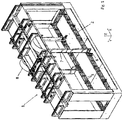
- the illustrated exemplary pretreatment chamber 1 of a pretreatment system has a distribution device 2.
- the distribution device 2 serves to distribute the pretreatment media in the pretreatment chamber 1.
- the distribution device 2 advantageously has a plurality of distribution lines 3.
- the distribution pipes 3 distribute the pretreatment media in the horizontal directions X and Y.
- the distribution lines 3 each supply a plurality of delivery devices 4 with the pretreatment media.
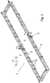
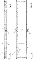
- the flow path for liquid media of the individual distribution lines 3 each has a constant gradient in the direction of an emptying device 6.
- the individual drainage devices 6 each serve to drain a distribution line 3.
- the constant gradient of the flow path for liquid media in the distribution lines 3 is ensured by the fact that the distribution lines 3 themselves each have a constant gradient towards the respective drainage device 6.
- the gradient of the supply lines 3 is 0.6 ° in the example shown.
- the distribution device 2 in the pretreatment chamber 1 can advantageously be moved in the vertical direction Z.
- the pretreatment area 5 also moves in the vertical direction Z through the spatial area of the pretreatment chamber 1 in which the workpieces to be pretreated are located.
- the individual emptying devices 6 are advantageously designed to discharge the pretreatment media from the respective distribution lines 3 into the interior of the pretreatment chamber 1.
- the emptying devices 6 are designed in the example shown as shut-off valves, which are preferably by a suitable control device can be opened and / or closed remotely.
- the distribution device 2 is preferably arranged in a ring around the pretreatment area 5.
- the distribution lines 3 are more preferably arranged in a ring around the pretreatment area 5.
- the delivery devices 4 are advantageously arranged in a ring-shaped manner around the pretreatment area 5.
- the exemplary pretreatment system has supply devices 7.
- the supply devices 7 are advantageously designed by means of flexible lines, which are guided in their movement by means of deflection devices 8 when the distribution device 2 is moved in the vertical direction Z.
Landscapes
- Cleaning By Liquid Or Steam (AREA)
Claims (14)
- Installation de prétraitement pour la réalisation des prétraitements de pièces pour des traitements de surface, avec une chambre de prétraitement (1) pour recevoir les pièces pendant le prétraitement, et un dispositif de répartition (2) pour répartir des milieux de prétraitement dans la chambre de prétraitement (1), dans laquelle le dispositif de répartition (2) comporte une ligne de répartition (3) pour répartir des milieux de prétraitement dans une direction horizontale (X, Y), dans laquelle la ligne de répartition (3) comporte une pluralité de moyens de déchargement (4) pour décharger des milieux de prétraitement dans une zone de prétraitement (5) à l'intérieur de la chambre de prétraitement (1), dans laquelle le chemin d'écoulement pour des milieux liquides de la ligne de répartition (3) comporte une inclinaison continue dans une direction d'un moyen de vidange (6) pour vider la ligne de répartition (3),
caractérisé en ce
que le dispositif de répartition (2) est déplaçable verticalement dans la chambre de prétraitement (1), dans lequel le dispositif de répartition (2) est agencé de façon annulaire autour de la zone de prétraitement (5). - Installation de prétraitement selon la revendication 1,
caractérisé en ce
que l'installation de prétraitement, surtout le dispositif de répartition (2), comporte une pluralité de lignes de répartition (3). - Installation de prétraitement selon l'une quelconque des revendications précédentes,
caractérisé en ce
que le moyen de vidange (6) est conçu pour décharger des milieux de prétraitement à partir de la ligne de répartition (3) dans l'intérieur de la chambre de prétraitement (1). - Installation de prétraitement selon l'une quelconque des revendications précédentes,
caractérisé en ce
que les moyens de déchargement (4) sont des buses. - Installation de prétraitement selon l'une quelconque des revendications précédentes,
caractérisé en ce
que les moyens de déchargement (4) sont agencés de façon annulaire autour de la zone de prétraitement (5). - Installation de prétraitement selon l'une quelconque des revendications précédentes,
caractérisé en ce
que la ligne de répartition (3) et/ou la pluralité de lignes de répartition (3) sont agencées de façon annulaire autour de la zone de prétraitement (5). - Installation de prétraitement selon l'une quelconque des revendications précédentes,
caractérisé en ce
que l'installation de prétraitement, surtout le dispositif de répartition (2), comporte une pluralité de dispositifs de nettoyage, surtout des buses de nettoyage, pour le nettoyage de la chambre de prétraitement (1). - Installation de prétraitement selon la revendication 7,
caractérisé en ce
que les dispositifs de nettoyage sont agencés dans l'installation de prétraitement, surtout au dispositif de répartition (2), de manière à ce que qu'ils puissent fournir un milieu de nettoyage aux parois de la chambre de prétraitement (1). - Installation de prétraitement selon l'une quelconque des revendications précédentes,
caractérisé en ce
que l'installation de prétraitement comporte un dispositif collecteur pour collecter des milieux de prétraitement et/ou des milieux de nettoyage déchargés à l'intérieur de la chambre de prétraitement (1). - Installation de prétraitement selon la revendication 9,
caractérisé en ce
que le dispositif collecteur peut être raccordé facultativement à une pluralité de récipients. - Installation de prétraitement selon la revendication 10,
caractérisé en ce
qu'un dispositif de raccordement est prévu pour le raccordement facultatif des récipients individuels au dispositif collecteur. - Installation de prétraitement selon la revendication 11,
caractérisé en ce
que le chemin d'écoulement pour des milieux liquides du dispositif de raccordement comporte une inclinaison continue. - Installation de prétraitement selon la revendication 11 ou 12,
caractérisé en ce
que le dispositif de raccordement comporte un élément de raccordement pivotant, surtout un tube. - Installation de prétraitement selon la revendication 13,
caractérisé en ce
que l'élément de raccordement est monté rotatif autour d'un axe vertical.
Priority Applications (1)
| Application Number | Priority Date | Filing Date | Title |
|---|---|---|---|
| PL18163154T PL3378570T3 (pl) | 2017-03-22 | 2018-03-21 | Instalacja do obróbki wstępnej |
Applications Claiming Priority (1)
| Application Number | Priority Date | Filing Date | Title |
|---|---|---|---|
| DE202017001545.5U DE202017001545U1 (de) | 2017-03-22 | 2017-03-22 | Vorbehandlungsanlage |
Publications (2)
| Publication Number | Publication Date |
|---|---|
| EP3378570A1 EP3378570A1 (fr) | 2018-09-26 |
| EP3378570B1 true EP3378570B1 (fr) | 2021-08-11 |
Family
ID=61749950
Family Applications (1)
| Application Number | Title | Priority Date | Filing Date |
|---|---|---|---|
| EP18163154.0A Active EP3378570B1 (fr) | 2017-03-22 | 2018-03-21 | Installation de prétraitement |
Country Status (3)
| Country | Link |
|---|---|
| EP (1) | EP3378570B1 (fr) |
| DE (1) | DE202017001545U1 (fr) |
| PL (1) | PL3378570T3 (fr) |
Families Citing this family (1)
| Publication number | Priority date | Publication date | Assignee | Title |
|---|---|---|---|---|
| CN111330794B (zh) * | 2020-03-28 | 2021-06-04 | 南通市濠洲船舶工程有限公司 | 一种刷漆速干控制装置 |
Citations (1)
| Publication number | Priority date | Publication date | Assignee | Title |
|---|---|---|---|---|
| WO2016087684A1 (fr) * | 2014-12-03 | 2016-06-09 | Herreros Muñoz Ana Victoria | Procédé de recyclage de produits phytosanitaires, outil pour canaliser le liquide projeté et/ou pulvérisé par des équipements d'application de produits phytosanitaires, machine de collecte de liquide avec des produits phytosanitaires et installation pour le développement dudit procédé |
Family Cites Families (4)
| Publication number | Priority date | Publication date | Assignee | Title |
|---|---|---|---|---|
| GB873432A (en) * | 1958-01-06 | 1961-07-26 | Modernair Processes Ltd | Improvements relating to the treatment of metal and other surfaces with liquids |
| FR2599642B1 (fr) * | 1986-06-09 | 1988-12-09 | Serma Sarl | Cabine programmable de prelavage, lavage, pulverisation, atomisation, rincage, soufflage, sechage, pour l'industrie |
| FR2668401B1 (fr) * | 1990-10-26 | 1994-08-12 | Ict Moscatelli F | Dispositif de traitement de surfaces et procede de mise en óoeuvre de ce dispositif. |
| EP2492020B1 (fr) * | 2011-02-24 | 2013-11-06 | Rippert Besitzgesellschaft mbH & Co. KG | Chambre de prétraitement comprenant une évacuation des fluides de traitement séparée dans des récipients séparés |
-
2017
- 2017-03-22 DE DE202017001545.5U patent/DE202017001545U1/de not_active Expired - Lifetime
-
2018
- 2018-03-21 PL PL18163154T patent/PL3378570T3/pl unknown
- 2018-03-21 EP EP18163154.0A patent/EP3378570B1/fr active Active
Patent Citations (1)
| Publication number | Priority date | Publication date | Assignee | Title |
|---|---|---|---|---|
| WO2016087684A1 (fr) * | 2014-12-03 | 2016-06-09 | Herreros Muñoz Ana Victoria | Procédé de recyclage de produits phytosanitaires, outil pour canaliser le liquide projeté et/ou pulvérisé par des équipements d'application de produits phytosanitaires, machine de collecte de liquide avec des produits phytosanitaires et installation pour le développement dudit procédé |
Also Published As
| Publication number | Publication date |
|---|---|
| EP3378570A1 (fr) | 2018-09-26 |
| DE202017001545U1 (de) | 2018-06-25 |
| PL3378570T3 (pl) | 2021-12-20 |
Similar Documents
| Publication | Publication Date | Title |
|---|---|---|
| DE502006011143C5 (de) | Reinigungsanlage | |
| DE102015116196B3 (de) | Wasch- und/oder Reinigungsanlage | |
| EP1122338B1 (fr) | Appareil pour projeter des liquides de décapage ou de rinçage sur des objets métalliques | |
| WO2018024772A1 (fr) | Dispositif panier de rinçage pour bouteilles et lave-vaisselle doté d'un tel dispositif | |
| DE2150345A1 (de) | Verfahren und einrichtung zur biologischen abwasserreinigung mittels eines feinkorntropfkoerpers | |
| DE102017104842A1 (de) | Mischer mit Reinigungsdüse | |
| DE102007011957B4 (de) | Flaschenkastenreiniger | |
| EP2492020B1 (fr) | Chambre de prétraitement comprenant une évacuation des fluides de traitement séparée dans des récipients séparés | |
| EP3378570B1 (fr) | Installation de prétraitement | |
| EP4437924A1 (fr) | Dispositif de dosage | |
| EP1957247B1 (fr) | Dispositif et procédé de nettoyage d'un bloc scie de galettes semi-conductrices | |
| DE3903343C2 (de) | Verfahren zur Abwasserreinigung durch Ionenaustauscherharze | |
| DE4308757C2 (de) | Vorrichtung zum Abspritzen von Oberflächen | |
| DE2627266A1 (de) | Vorrichtung zum behandeln des filterkuchens bei einem bewegten filter | |
| WO2010142358A1 (fr) | Dispositif destiné à humidifier un produit en vrac | |
| DE102013112947A1 (de) | Fallschachtanordnung, Vorrichtung und Verfahren zum Reinigen eines Fallschachts, insbesondere in einer Vorrichtung zur Beleimung von Partikeln | |
| DE102019117084A1 (de) | Reinigungsanlage und Reinigungsverfahren insbesondere für Behandlungsanlagen in der Lackiertechnik | |
| DE102017123632A1 (de) | Kontinuierlich arbeitende Teigknetvorrichtung | |
| DE102019130611B3 (de) | Reinigungsvorrichtung, Behälter und Verfahren zur Reinigung und/oder Spülung | |
| DE102017011242A1 (de) | Behälter mit einer Vorrichtung zur Innenreinigung | |
| DE4434407A1 (de) | Anlage zum Reinigen und Befüllen einer Folge von Getränkebehältern | |
| DE4237831C2 (de) | Einrichtung zum Regulieren eines Sp}lmittelflusses in Melkleitungen von Rohrmelkanlagen | |
| DE60226348T2 (de) | Vorrichtung zum entfernen und absaugen von an aussenwänden von pulveransaugrohren haftendem pulver | |
| CH687856A5 (de) | Verfahren und Vorrichtung zur fortlaufenden Kennzeichnung von langgestrecktem Gut. | |
| DE10210983B4 (de) | Industrielle Reinigungsanlage mit einer Selektionsvorrichtung für gebrauchte Reinigungsflüssigkeiten |
Legal Events
| Date | Code | Title | Description |
|---|---|---|---|
| PUAI | Public reference made under article 153(3) epc to a published international application that has entered the european phase |
Free format text: ORIGINAL CODE: 0009012 |
|
| STAA | Information on the status of an ep patent application or granted ep patent |
Free format text: STATUS: THE APPLICATION HAS BEEN PUBLISHED |
|
| AK | Designated contracting states |
Kind code of ref document: A1 Designated state(s): AL AT BE BG CH CY CZ DE DK EE ES FI FR GB GR HR HU IE IS IT LI LT LU LV MC MK MT NL NO PL PT RO RS SE SI SK SM TR |
|
| AX | Request for extension of the european patent |
Extension state: BA ME |
|
| STAA | Information on the status of an ep patent application or granted ep patent |
Free format text: STATUS: REQUEST FOR EXAMINATION WAS MADE |
|
| 17P | Request for examination filed |
Effective date: 20190307 |
|
| RBV | Designated contracting states (corrected) |
Designated state(s): AL AT BE BG CH CY CZ DE DK EE ES FI FR GB GR HR HU IE IS IT LI LT LU LV MC MK MT NL NO PL PT RO RS SE SI SK SM TR |
|
| STAA | Information on the status of an ep patent application or granted ep patent |
Free format text: STATUS: EXAMINATION IS IN PROGRESS |
|
| 17Q | First examination report despatched |
Effective date: 20200805 |
|
| GRAP | Despatch of communication of intention to grant a patent |
Free format text: ORIGINAL CODE: EPIDOSNIGR1 |
|
| STAA | Information on the status of an ep patent application or granted ep patent |
Free format text: STATUS: GRANT OF PATENT IS INTENDED |
|
| INTG | Intention to grant announced |
Effective date: 20210514 |
|
| GRAS | Grant fee paid |
Free format text: ORIGINAL CODE: EPIDOSNIGR3 |
|
| GRAA | (expected) grant |
Free format text: ORIGINAL CODE: 0009210 |
|
| STAA | Information on the status of an ep patent application or granted ep patent |
Free format text: STATUS: THE PATENT HAS BEEN GRANTED |
|
| AK | Designated contracting states |
Kind code of ref document: B1 Designated state(s): AL AT BE BG CH CY CZ DE DK EE ES FI FR GB GR HR HU IE IS IT LI LT LU LV MC MK MT NL NO PL PT RO RS SE SI SK SM TR |
|
| RIN1 | Information on inventor provided before grant (corrected) |
Inventor name: HAKENKAMP, NIKLAS Inventor name: SCHLESIGER, JOHANNES Inventor name: KREIENBAUM, NICO |
|
| REG | Reference to a national code |
Ref country code: CH Ref legal event code: EP |
|
| REG | Reference to a national code |
Ref country code: DE Ref legal event code: R096 Ref document number: 502018006490 Country of ref document: DE |
|
| REG | Reference to a national code |
Ref country code: NL Ref legal event code: FP Ref country code: IE Ref legal event code: FG4D Free format text: LANGUAGE OF EP DOCUMENT: GERMAN Ref country code: AT Ref legal event code: REF Ref document number: 1418838 Country of ref document: AT Kind code of ref document: T Effective date: 20210915 |
|
| REG | Reference to a national code |
Ref country code: LT Ref legal event code: MG9D |
|
| PG25 | Lapsed in a contracting state [announced via postgrant information from national office to epo] |
Ref country code: SE Free format text: LAPSE BECAUSE OF FAILURE TO SUBMIT A TRANSLATION OF THE DESCRIPTION OR TO PAY THE FEE WITHIN THE PRESCRIBED TIME-LIMIT Effective date: 20210811 Ref country code: RS Free format text: LAPSE BECAUSE OF FAILURE TO SUBMIT A TRANSLATION OF THE DESCRIPTION OR TO PAY THE FEE WITHIN THE PRESCRIBED TIME-LIMIT Effective date: 20210811 Ref country code: HR Free format text: LAPSE BECAUSE OF FAILURE TO SUBMIT A TRANSLATION OF THE DESCRIPTION OR TO PAY THE FEE WITHIN THE PRESCRIBED TIME-LIMIT Effective date: 20210811 Ref country code: FI Free format text: LAPSE BECAUSE OF FAILURE TO SUBMIT A TRANSLATION OF THE DESCRIPTION OR TO PAY THE FEE WITHIN THE PRESCRIBED TIME-LIMIT Effective date: 20210811 Ref country code: ES Free format text: LAPSE BECAUSE OF FAILURE TO SUBMIT A TRANSLATION OF THE DESCRIPTION OR TO PAY THE FEE WITHIN THE PRESCRIBED TIME-LIMIT Effective date: 20210811 Ref country code: NO Free format text: LAPSE BECAUSE OF FAILURE TO SUBMIT A TRANSLATION OF THE DESCRIPTION OR TO PAY THE FEE WITHIN THE PRESCRIBED TIME-LIMIT Effective date: 20211111 Ref country code: PT Free format text: LAPSE BECAUSE OF FAILURE TO SUBMIT A TRANSLATION OF THE DESCRIPTION OR TO PAY THE FEE WITHIN THE PRESCRIBED TIME-LIMIT Effective date: 20211213 Ref country code: BG Free format text: LAPSE BECAUSE OF FAILURE TO SUBMIT A TRANSLATION OF THE DESCRIPTION OR TO PAY THE FEE WITHIN THE PRESCRIBED TIME-LIMIT Effective date: 20211111 Ref country code: LT Free format text: LAPSE BECAUSE OF FAILURE TO SUBMIT A TRANSLATION OF THE DESCRIPTION OR TO PAY THE FEE WITHIN THE PRESCRIBED TIME-LIMIT Effective date: 20210811 |
|
| PG25 | Lapsed in a contracting state [announced via postgrant information from national office to epo] |
Ref country code: LV Free format text: LAPSE BECAUSE OF FAILURE TO SUBMIT A TRANSLATION OF THE DESCRIPTION OR TO PAY THE FEE WITHIN THE PRESCRIBED TIME-LIMIT Effective date: 20210811 Ref country code: GR Free format text: LAPSE BECAUSE OF FAILURE TO SUBMIT A TRANSLATION OF THE DESCRIPTION OR TO PAY THE FEE WITHIN THE PRESCRIBED TIME-LIMIT Effective date: 20211112 |
|
| PG25 | Lapsed in a contracting state [announced via postgrant information from national office to epo] |
Ref country code: DK Free format text: LAPSE BECAUSE OF FAILURE TO SUBMIT A TRANSLATION OF THE DESCRIPTION OR TO PAY THE FEE WITHIN THE PRESCRIBED TIME-LIMIT Effective date: 20210811 |
|
| REG | Reference to a national code |
Ref country code: DE Ref legal event code: R097 Ref document number: 502018006490 Country of ref document: DE |
|
| PG25 | Lapsed in a contracting state [announced via postgrant information from national office to epo] |
Ref country code: SM Free format text: LAPSE BECAUSE OF FAILURE TO SUBMIT A TRANSLATION OF THE DESCRIPTION OR TO PAY THE FEE WITHIN THE PRESCRIBED TIME-LIMIT Effective date: 20210811 Ref country code: SK Free format text: LAPSE BECAUSE OF FAILURE TO SUBMIT A TRANSLATION OF THE DESCRIPTION OR TO PAY THE FEE WITHIN THE PRESCRIBED TIME-LIMIT Effective date: 20210811 Ref country code: RO Free format text: LAPSE BECAUSE OF FAILURE TO SUBMIT A TRANSLATION OF THE DESCRIPTION OR TO PAY THE FEE WITHIN THE PRESCRIBED TIME-LIMIT Effective date: 20210811 Ref country code: EE Free format text: LAPSE BECAUSE OF FAILURE TO SUBMIT A TRANSLATION OF THE DESCRIPTION OR TO PAY THE FEE WITHIN THE PRESCRIBED TIME-LIMIT Effective date: 20210811 Ref country code: AL Free format text: LAPSE BECAUSE OF FAILURE TO SUBMIT A TRANSLATION OF THE DESCRIPTION OR TO PAY THE FEE WITHIN THE PRESCRIBED TIME-LIMIT Effective date: 20210811 |
|
| PLBE | No opposition filed within time limit |
Free format text: ORIGINAL CODE: 0009261 |
|
| STAA | Information on the status of an ep patent application or granted ep patent |
Free format text: STATUS: NO OPPOSITION FILED WITHIN TIME LIMIT |
|
| 26N | No opposition filed |
Effective date: 20220512 |
|
| PG25 | Lapsed in a contracting state [announced via postgrant information from national office to epo] |
Ref country code: IT Free format text: LAPSE BECAUSE OF FAILURE TO SUBMIT A TRANSLATION OF THE DESCRIPTION OR TO PAY THE FEE WITHIN THE PRESCRIBED TIME-LIMIT Effective date: 20210811 |
|
| PG25 | Lapsed in a contracting state [announced via postgrant information from national office to epo] |
Ref country code: SI Free format text: LAPSE BECAUSE OF FAILURE TO SUBMIT A TRANSLATION OF THE DESCRIPTION OR TO PAY THE FEE WITHIN THE PRESCRIBED TIME-LIMIT Effective date: 20210811 |
|
| PG25 | Lapsed in a contracting state [announced via postgrant information from national office to epo] |
Ref country code: MC Free format text: LAPSE BECAUSE OF FAILURE TO SUBMIT A TRANSLATION OF THE DESCRIPTION OR TO PAY THE FEE WITHIN THE PRESCRIBED TIME-LIMIT Effective date: 20210811 |
|
| GBPC | Gb: european patent ceased through non-payment of renewal fee |
Effective date: 20220321 |
|
| REG | Reference to a national code |
Ref country code: BE Ref legal event code: MM Effective date: 20220331 |
|
| PG25 | Lapsed in a contracting state [announced via postgrant information from national office to epo] |
Ref country code: LU Free format text: LAPSE BECAUSE OF NON-PAYMENT OF DUE FEES Effective date: 20220321 Ref country code: IE Free format text: LAPSE BECAUSE OF NON-PAYMENT OF DUE FEES Effective date: 20220321 Ref country code: GB Free format text: LAPSE BECAUSE OF NON-PAYMENT OF DUE FEES Effective date: 20220321 |
|
| PG25 | Lapsed in a contracting state [announced via postgrant information from national office to epo] |
Ref country code: BE Free format text: LAPSE BECAUSE OF NON-PAYMENT OF DUE FEES Effective date: 20220331 |
|
| PLAA | Information modified related to event that no opposition was filed |
Free format text: ORIGINAL CODE: 0009299DELT |
|
| PLBE | No opposition filed within time limit |
Free format text: ORIGINAL CODE: 0009261 |
|
| REG | Reference to a national code |
Ref country code: CH Ref legal event code: PK Free format text: BERICHTIGUNGEN |
|
| R26N | No opposition filed (corrected) |
Effective date: 20220512 |
|
| RIN2 | Information on inventor provided after grant (corrected) |
Inventor name: SCHOENING, THOMAS |
|
| PG25 | Lapsed in a contracting state [announced via postgrant information from national office to epo] |
Ref country code: HU Free format text: LAPSE BECAUSE OF FAILURE TO SUBMIT A TRANSLATION OF THE DESCRIPTION OR TO PAY THE FEE WITHIN THE PRESCRIBED TIME-LIMIT; INVALID AB INITIO Effective date: 20180321 |
|
| PG25 | Lapsed in a contracting state [announced via postgrant information from national office to epo] |
Ref country code: MK Free format text: LAPSE BECAUSE OF FAILURE TO SUBMIT A TRANSLATION OF THE DESCRIPTION OR TO PAY THE FEE WITHIN THE PRESCRIBED TIME-LIMIT Effective date: 20210811 Ref country code: CY Free format text: LAPSE BECAUSE OF FAILURE TO SUBMIT A TRANSLATION OF THE DESCRIPTION OR TO PAY THE FEE WITHIN THE PRESCRIBED TIME-LIMIT Effective date: 20210811 |
|
| PG25 | Lapsed in a contracting state [announced via postgrant information from national office to epo] |
Ref country code: MT Free format text: LAPSE BECAUSE OF FAILURE TO SUBMIT A TRANSLATION OF THE DESCRIPTION OR TO PAY THE FEE WITHIN THE PRESCRIBED TIME-LIMIT Effective date: 20210811 |
|
| PGFP | Annual fee paid to national office [announced via postgrant information from national office to epo] |
Ref country code: DE Payment date: 20250502 Year of fee payment: 8 |
|
| PGFP | Annual fee paid to national office [announced via postgrant information from national office to epo] |
Ref country code: CH Payment date: 20250423 Year of fee payment: 8 |
|
| PG25 | Lapsed in a contracting state [announced via postgrant information from national office to epo] |
Ref country code: TR Free format text: LAPSE BECAUSE OF FAILURE TO SUBMIT A TRANSLATION OF THE DESCRIPTION OR TO PAY THE FEE WITHIN THE PRESCRIBED TIME-LIMIT Effective date: 20210811 |
|
| REG | Reference to a national code |
Ref country code: CH Ref legal event code: U11 Free format text: ST27 STATUS EVENT CODE: U-0-0-U10-U11 (AS PROVIDED BY THE NATIONAL OFFICE) Effective date: 20260401 |
|
| PGFP | Annual fee paid to national office [announced via postgrant information from national office to epo] |
Ref country code: AT Payment date: 20260319 Year of fee payment: 9 |
|
| PGFP | Annual fee paid to national office [announced via postgrant information from national office to epo] |
Ref country code: NL Payment date: 20260323 Year of fee payment: 9 |
|
| PGFP | Annual fee paid to national office [announced via postgrant information from national office to epo] |
Ref country code: FR Payment date: 20260325 Year of fee payment: 9 |
|
| PGFP | Annual fee paid to national office [announced via postgrant information from national office to epo] |
Ref country code: CZ Payment date: 20260306 Year of fee payment: 9 |
|
| PGFP | Annual fee paid to national office [announced via postgrant information from national office to epo] |
Ref country code: PL Payment date: 20260302 Year of fee payment: 9 |