EP3378570B1 - Pretreatment installation - Google Patents
Pretreatment installation Download PDFInfo
- Publication number
- EP3378570B1 EP3378570B1 EP18163154.0A EP18163154A EP3378570B1 EP 3378570 B1 EP3378570 B1 EP 3378570B1 EP 18163154 A EP18163154 A EP 18163154A EP 3378570 B1 EP3378570 B1 EP 3378570B1
- Authority
- EP
- European Patent Office
- Prior art keywords
- pretreatment
- media
- installation according
- chamber
- distribution line
- Prior art date
- Legal status (The legal status is an assumption and is not a legal conclusion. Google has not performed a legal analysis and makes no representation as to the accuracy of the status listed.)
- Active
Links
Images
Classifications
-
- B—PERFORMING OPERATIONS; TRANSPORTING
- B05—SPRAYING OR ATOMISING IN GENERAL; APPLYING FLUENT MATERIALS TO SURFACES, IN GENERAL
- B05B—SPRAYING APPARATUS; ATOMISING APPARATUS; NOZZLES
- B05B16/00—Spray booths
- B05B16/20—Arrangements for spraying in combination with other operations, e.g. drying; Arrangements enabling a combination of spraying operations
-
- B—PERFORMING OPERATIONS; TRANSPORTING
- B05—SPRAYING OR ATOMISING IN GENERAL; APPLYING FLUENT MATERIALS TO SURFACES, IN GENERAL
- B05B—SPRAYING APPARATUS; ATOMISING APPARATUS; NOZZLES
- B05B14/00—Arrangements for collecting, re-using or eliminating excess spraying material
- B05B14/40—Arrangements for collecting, re-using or eliminating excess spraying material for use in spray booths
-
- B—PERFORMING OPERATIONS; TRANSPORTING
- B05—SPRAYING OR ATOMISING IN GENERAL; APPLYING FLUENT MATERIALS TO SURFACES, IN GENERAL
- B05B—SPRAYING APPARATUS; ATOMISING APPARATUS; NOZZLES
- B05B1/00—Nozzles, spray heads or other outlets, with or without auxiliary devices such as valves, heating means
- B05B1/14—Nozzles, spray heads or other outlets, with or without auxiliary devices such as valves, heating means with multiple outlet openings; with strainers in or outside the outlet opening
- B05B1/20—Perforated pipes or troughs, e.g. spray booms; Outlet elements therefor
- B05B1/202—Perforated pipes or troughs, e.g. spray booms; Outlet elements therefor comprising inserted outlet elements
-
- B—PERFORMING OPERATIONS; TRANSPORTING
- B05—SPRAYING OR ATOMISING IN GENERAL; APPLYING FLUENT MATERIALS TO SURFACES, IN GENERAL
- B05B—SPRAYING APPARATUS; ATOMISING APPARATUS; NOZZLES
- B05B1/00—Nozzles, spray heads or other outlets, with or without auxiliary devices such as valves, heating means
- B05B1/14—Nozzles, spray heads or other outlets, with or without auxiliary devices such as valves, heating means with multiple outlet openings; with strainers in or outside the outlet opening
- B05B1/20—Perforated pipes or troughs, e.g. spray booms; Outlet elements therefor
- B05B1/205—Perforated pipes or troughs, e.g. spray booms; Outlet elements therefor characterised by the longitudinal shape of the elongated body
- B05B1/207—Perforated pipes or troughs, e.g. spray booms; Outlet elements therefor characterised by the longitudinal shape of the elongated body the elongated body being a closed loop
-
- B—PERFORMING OPERATIONS; TRANSPORTING
- B05—SPRAYING OR ATOMISING IN GENERAL; APPLYING FLUENT MATERIALS TO SURFACES, IN GENERAL
- B05B—SPRAYING APPARATUS; ATOMISING APPARATUS; NOZZLES
- B05B15/00—Details of spraying plant or spraying apparatus not otherwise provided for; Accessories
- B05B15/60—Arrangements for mounting, supporting or holding spraying apparatus
- B05B15/68—Arrangements for adjusting the position of spray heads
-
- Y—GENERAL TAGGING OF NEW TECHNOLOGICAL DEVELOPMENTS; GENERAL TAGGING OF CROSS-SECTIONAL TECHNOLOGIES SPANNING OVER SEVERAL SECTIONS OF THE IPC; TECHNICAL SUBJECTS COVERED BY FORMER USPC CROSS-REFERENCE ART COLLECTIONS [XRACs] AND DIGESTS
- Y02—TECHNOLOGIES OR APPLICATIONS FOR MITIGATION OR ADAPTATION AGAINST CLIMATE CHANGE
- Y02P—CLIMATE CHANGE MITIGATION TECHNOLOGIES IN THE PRODUCTION OR PROCESSING OF GOODS
- Y02P70/00—Climate change mitigation technologies in the production process for final industrial or consumer products
- Y02P70/10—Greenhouse gas [GHG] capture, material saving, heat recovery or other energy efficient measures, e.g. motor control, characterised by manufacturing processes, e.g. for rolling metal or metal working
Definitions
- the invention relates to a pretreatment plant according to the preamble of claim 1.
- a pretreatment in the context of the present application is to be understood as meaning preparatory surface treatments that are carried out in preparation for a surface treatment associated with a layer application. These include, in particular, degreasing, phosphating, pickling and rinsing with demineralized water.
- the pretreatment is usually followed by a drying of the workpieces before the surface treatment is carried out.
- the surface treatment is usually a lacquer coating or a powder coating.
- Such pretreatment systems are used to subject workpieces that are to be subjected to a surface treatment to a treatment with liquid media.
- pre-treatment systems are often designed in such a way that the workpieces pass through different pre-treatment chambers or a long tunnel.
- a different pretreatment step is carried out in each of the pretreatment chambers or in different sections within the tunnel.
- This has the advantage that only one pretreatment medium is used in each chamber or each section.
- the pretreatment media are collected in basins located below the tunnel or the chambers and recycled. This is particularly possible because in each Pre-treatment chamber or each section, a single pre-treatment medium is preferably used. Mixing of the different pretreatment media can thus be largely prevented.
- Such pretreatment systems with a plurality of pretreatment chambers or sections represent a comparatively high minimum investment in order to implement the plurality of pretreatment chambers.
- Another disadvantage is the high space requirement, depending on the requirements of the individual process steps. It goes without saying that such a pretreatment system can only be operated economically if a correspondingly high throughput of workpieces is achieved. Furthermore, the workpieces must always go through the same pretreatment steps so that the pretreatment system operates as continuously as possible. However, this is often only the case in series productions aimed at high volumes.
- Such pretreatment systems regularly have distribution devices to the pretreatment media in to distribute the pretreatment chamber.
- the distribution devices regularly have a plurality of delivery devices which deliver the preparation media into a preparation area in the interior of the pretreatment chamber in which the workpieces to be pretreated are located.
- the pretreatment area In order to enable economical pretreatment, the pretreatment area must have a certain size in order to be able to accommodate a sufficiently large amount of workpieces for their simultaneous pretreatment.
- the dispensing devices are therefore supplied with liquid pretreatment media through a distribution line.
- the distribution line serves, among other things, to distribute the preparation media in the horizontal direction in the pretreatment chamber and in particular to the individual dispensing devices.
- pretreatment media In practice, however, it is possible for pretreatment media to accumulate in the distribution line.
- additional costs are mainly caused by the media required for flushing the lines, their professional disposal and the non-productive times required for flushing in the operation of the pretreatment system.
- a pretreatment system according to the preamble of claim 1 is known.
- WO 2016/087684 A1 is not a pretreatment system, but a cleaning system for cleaning equipment for spraying crop protection agents.
- This non-generic document describes a distribution line in a facility which has dispensing nozzles. In one embodiment, this output device can be moved horizontally and vertically.
- the invention is based on the object of providing a pretreatment system in which a plurality of pretreatment steps can be carried out in a single pretreatment chamber in which the disadvantages of the prior art described above do not occur or at least to a lesser extent.
- the object is achieved in that the flow path for liquid media in the distribution line has a constant gradient in the direction of an emptying device for emptying the distribution line.
- a constant gradient in the flow path leads to the preparation media flowing under the influence of gravity - at least largely - completely in the direction of the emptying device.
- the distribution device in the pretreatment chamber is vertical movable. This makes it possible to use a large space within the pretreatment chamber with a limited number of dispensing devices.
- the distribution device itself can also be made smaller and more cost-effective as a result, since it only has to extend over part of the height of the pretreatment chamber.
- the distribution device is arranged in a ring around the pretreatment area. Such a ring-shaped arrangement enables a uniform application of the pretreatment medium on all sides to the workpieces located in the pretreatment area.
- the pretreatment area that is to say the area into which the dispensing devices dispense the pretreatment media, is also moved vertically inside the pretreatment chamber.
- the constant gradient has the advantage that the medium used for flushing also flows through the constant gradient under the influence of gravity in the direction of the emptying device. On the one hand, this reduces the consumption of the medium used for rinsing, and on the other hand there is a mixing of residues of the medium used for rinsing prevented or at least largely prevented with the pretreatment medium used after rinsing.
- the constant gradient of the flow path of the distribution line can be implemented, for example, in that the distribution line itself has a constant gradient in the direction of the emptying devices.
- a pipeline with a constant cross section can be used, which is arranged with a corresponding gradient towards the emptying device.
- the emptying device does not necessarily have to be arranged at one end of the distribution line. Rather, it is also possible to arrange the emptying device at any point along the distribution line.
- the flow path then preferably has a constant gradient from all directions towards the emptying device. In other words, this means that the emptying device is preferably arranged at the lowest point of the flow path of the media in the distribution line. This can be achieved, for example, by arranging the emptying device at the lowest point of the distribution line itself.
- the pretreatment system in particular the distribution device, can advantageously have a plurality of distribution lines. This enables, for example, an alternating operation of two distribution lines, as a result of which non-productive times, for example for flushing and / or emptying the distribution lines, can be reduced even further.
- the emptying device is preferably designed to discharge pretreatment media from the distribution line into the interior of the pretreatment chamber.
- the emptying device releases the pretreatment media directly into the interior of the pretreatment chambers.
- the emptying device can be designed in a comparatively simple manner. In the simplest case, it can be a shut-off valve that is simply opened to drain the distribution line.
- the dispensing devices which may be nozzles, for example, are preferably arranged in a ring around the pretreatment area. This distribution of the delivery devices also favors the uniform application on all sides of the workpieces located in the pretreatment area.
- the distribution line is arranged in a ring around the pretreatment area.
- Such an arrangement of the distribution line advantageously enables the supply of those distributed via the distribution device Dispensing devices, in particular if these are arranged in a ring-shaped manner around the pretreatment area.
- the pretreatment system has a plurality of cleaning devices for cleaning the pretreatment chambers.
- These cleaning devices can be nozzles, for example. Such cleaning devices make it possible to clean or rinse the interior of the pretreatment chambers.
- the cleaning devices are preferably arranged on the distribution device.
- this has the advantage that the entire interior, or at least most of the interior, of the pretreatment chamber can be cleaned or rinsed with a small number of cleaning devices.
- the cleaning devices are arranged in the pretreatment system, in particular on the distribution device, in such a way that they can deliver a cleaning medium to the walls of the pretreatment chambers.
- This can be, for example, nozzles oriented in the direction of the walls of the pretreatment chamber.
- the pretreatment system particularly preferably has a collecting device for collecting the pretreatment media released into the interior of the pretreatment chamber.
- a collecting device has the advantage that the collected pretreatment media can optionally be reused.
- the collection facility is preferably arranged in the area of the bottom of the pretreatment chamber.
- the collecting device is particularly preferably a design of the bottom with a, preferably constant, slope towards a deepest point of the bottom of the pretreatment chamber. Such a design of the bottom leads to the pretreatment media and / or possibly media for cleaning and / or rinsing the pretreatment chamber collecting in the area of the deepest point of the bottom.
- the collecting device can preferably be optionally connected to a plurality of containers. In this way, different pretreatment media, media for rinsing and / or media for cleaning can be collected in separate containers. In this way, the media are - at least largely - unmixed, which favors recycling or disposal.
- the pretreatment system preferably has a connecting device.
- the flow path for liquid media of the connecting device is preferably designed in such a way that it has a constant gradient. In this way it can be avoided that media collect in the connection device and thus lead to contamination of other media.
- the connecting device preferably has a pivotable connecting element.
- This can be a pipe, for example.
- the connecting element is preferably mounted rotatably about a vertical axis. The rotation of the connecting element about a vertical axis in particular allows the realization of a constant gradient in the flow path in a simple manner, regardless of the position of its rotating or pivoting range at which the connecting element is located.
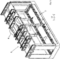
- the illustrated exemplary pretreatment chamber 1 of a pretreatment system has a distribution device 2.
- the distribution device 2 serves to distribute the pretreatment media in the pretreatment chamber 1.
- the distribution device 2 advantageously has a plurality of distribution lines 3.
- the distribution pipes 3 distribute the pretreatment media in the horizontal directions X and Y.
- the distribution lines 3 each supply a plurality of delivery devices 4 with the pretreatment media.
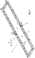
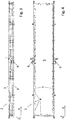
- the flow path for liquid media of the individual distribution lines 3 each has a constant gradient in the direction of an emptying device 6.
- the individual drainage devices 6 each serve to drain a distribution line 3.
- the constant gradient of the flow path for liquid media in the distribution lines 3 is ensured by the fact that the distribution lines 3 themselves each have a constant gradient towards the respective drainage device 6.
- the gradient of the supply lines 3 is 0.6 ° in the example shown.
- the distribution device 2 in the pretreatment chamber 1 can advantageously be moved in the vertical direction Z.
- the pretreatment area 5 also moves in the vertical direction Z through the spatial area of the pretreatment chamber 1 in which the workpieces to be pretreated are located.
- the individual emptying devices 6 are advantageously designed to discharge the pretreatment media from the respective distribution lines 3 into the interior of the pretreatment chamber 1.
- the emptying devices 6 are designed in the example shown as shut-off valves, which are preferably by a suitable control device can be opened and / or closed remotely.
- the distribution device 2 is preferably arranged in a ring around the pretreatment area 5.
- the distribution lines 3 are more preferably arranged in a ring around the pretreatment area 5.
- the delivery devices 4 are advantageously arranged in a ring-shaped manner around the pretreatment area 5.
- the exemplary pretreatment system has supply devices 7.
- the supply devices 7 are advantageously designed by means of flexible lines, which are guided in their movement by means of deflection devices 8 when the distribution device 2 is moved in the vertical direction Z.
Landscapes
- Cleaning By Liquid Or Steam (AREA)
Description
Die Erfindung betrifft eine Vorbehandlungsanlage nach dem Oberbegriff des Anspruchs 1.The invention relates to a pretreatment plant according to the preamble of
Unter einer Vorbehandlung im Sinne der vorliegenden Anmeldung sind vorbereitende Oberflächenbehandlungen zu verstehen, die zur Vorbereitung einer mit einem Schichtauftrag verbundenen Oberflächenbehandlung durchgeführt werden. Hierzu zählen insbesondere Entfetten, Phosphatieren, Beizen und Spülen mit demineralisiertem Wasser.A pretreatment in the context of the present application is to be understood as meaning preparatory surface treatments that are carried out in preparation for a surface treatment associated with a layer application. These include, in particular, degreasing, phosphating, pickling and rinsing with demineralized water.
An die Vorbehandlung schließt sich in der Regel zunächst eine Trocknung der Werkstücke an, bevor die Oberflächenbehandlung durchgeführt wird. Bei der Oberflächenbehandlung handelt es sich regelmäßig um eine Lackbeschichtung oder eine Pulverbeschichtung.The pretreatment is usually followed by a drying of the workpieces before the surface treatment is carried out. The surface treatment is usually a lacquer coating or a powder coating.
Derartige Vorbehandlungsanlagen dienen dazu, Werkstücke, die einer Oberflächenbehandlung unterzogen werden sollen, einer Behandlung mit flüssigen Medien zu unterziehen.Such pretreatment systems are used to subject workpieces that are to be subjected to a surface treatment to a treatment with liquid media.
Je nach Einsatzzweck werden derartige Vorbehandlungs-anlagen häufig so konzipiert, dass die Werkstücke verschiedene Vorbehandlungskammern oder einen langen Tunnel durchlaufen. In jeder der Vorbehandlungskammern bzw. in verschiedenen Abschnitten innerhalb des Tunnels wird ein anderer Vorbehandlungsschritt durchgeführt. Dies hat den Vorteil, dass in jeder Kammer bzw. jedem Abschnitt lediglich ein Vorbehandlungsmedium verwendet wird. Die Vorbehandlungsmedien werden in unterhalb des Tunnels oder der Kammern befindlichen Becken gesammelt und wiederverwertet. Dies ist insbesondere deswegen möglich, da in jeder Vorbehandlungskammer bzw. jedem Abschnitt bevorzugt ein einziges Vorbehandlungsmedium zum Einsatz kommt. Eine Vermischung der unterschiedlichen Vorbehandlungsmedien kann somit weitestgehend verhindert werden.Depending on the intended use, such pre-treatment systems are often designed in such a way that the workpieces pass through different pre-treatment chambers or a long tunnel. A different pretreatment step is carried out in each of the pretreatment chambers or in different sections within the tunnel. This has the advantage that only one pretreatment medium is used in each chamber or each section. The pretreatment media are collected in basins located below the tunnel or the chambers and recycled. This is particularly possible because in each Pre-treatment chamber or each section, a single pre-treatment medium is preferably used. Mixing of the different pretreatment media can thus be largely prevented.
Solche Vorbehandlungsanlagen mit einer Mehrzahl Vorbehandlungskammern oder Abschnitten stellen jedoch eine vergleichsweise hohe Mindestinvestition dar, um die Mehrzahl Vorbehandlungskammern zu realisieren. Ein weiterer Nachteil ist der hohe Platzbedarf, je nach Anforderungen der einzelnen Prozessschritte. Es versteht sich, dass eine derartige Vorbehandlungsanlage nur dann wirtschaftlich sinnvoll betrieben werden kann, wenn ein entsprechend hoher Durchsatz an Werkstücken erzielt wird. Weiterhin müssen die Werkstücke immer die gleichen Vorbehandlungsschritte durchlaufen, damit ein möglichst kontinuierlicher Betrieb der Vorbehandlungsanlage gewährleistet wird. Dies ist jedoch oft nur in Serienproduktionen, die auf hohe Stückzahlen abzielen, der Fall.Such pretreatment systems with a plurality of pretreatment chambers or sections, however, represent a comparatively high minimum investment in order to implement the plurality of pretreatment chambers. Another disadvantage is the high space requirement, depending on the requirements of the individual process steps. It goes without saying that such a pretreatment system can only be operated economically if a correspondingly high throughput of workpieces is achieved. Furthermore, the workpieces must always go through the same pretreatment steps so that the pretreatment system operates as continuously as possible. However, this is often only the case in series productions aimed at high volumes.
In der Praxis ist es oft wünschenswert, dass für kleine Serien oder einzelne Werkstücke eine entsprechende Vorbehandlung durchgeführt werden kann, ohne dass die hohen Investitionskosten für eine Vorbehandlungsanlage des vorgenannten Typs anfallen. Derartige Vorbehandlungsanlagen werden daher so konzipiert, dass eine Mehrzahl Vorbehandlungsschritte in einer einzelnen Kammer durchgeführt werden kann. Hierbei besteht regelmäßig das Problem, die Vorbehandlung unter wirtschaftlichen und ökologischen Gesichtspunkten sinnvoll zu gestalten.In practice, it is often desirable that a corresponding pretreatment can be carried out for small series or individual workpieces without incurring the high investment costs for a pretreatment system of the aforementioned type. Such pretreatment systems are therefore designed in such a way that a plurality of pretreatment steps can be carried out in a single chamber. Here there is regularly the problem of making the pretreatment sensible from an economic and ecological point of view.
Derartige Vorbehandlungsanlagen weisen regelmäßig Verteilungseinrichtungen auf, um die Vorbehandlungsmedien in der Vorbehandlungskammer zu verteilen. Die Verteilungseinrichtungen verfügen regelmäßig über eine Mehrzahl Abgabeeinrichtungen, die die Vorbereitungsmedien in einen Vorbereitungsbereich im Inneren der Vorbehandlungskammer, in dem sich die vorzubehandelnden Werkstücke befinden, abgeben.Such pretreatment systems regularly have distribution devices to the pretreatment media in to distribute the pretreatment chamber. The distribution devices regularly have a plurality of delivery devices which deliver the preparation media into a preparation area in the interior of the pretreatment chamber in which the workpieces to be pretreated are located.
Um eine wirtschaftliche Vorbehandlung zu ermöglichen, muss der Vorbehandlungsbereich eine gewisse Größe aufweisen, um eine hinreichend große Menge Werkstücke für deren gleichzeitige Vorbehandlung aufnehmen zu können. Die Abgabeeinrichtungen werden daher durch eine Verteilungsleitung mit flüssigen Vorbehandlungsmedien versorgt. Die Verteilungsleitung dient dabei unter anderem dazu, die Vorbereitungsmedien in horizontaler Richtung in der Vorbehandlungskammer und insbesondere auf die einzelnen Abgabeeinrichtungen zu verteilen.In order to enable economical pretreatment, the pretreatment area must have a certain size in order to be able to accommodate a sufficiently large amount of workpieces for their simultaneous pretreatment. The dispensing devices are therefore supplied with liquid pretreatment media through a distribution line. The distribution line serves, among other things, to distribute the preparation media in the horizontal direction in the pretreatment chamber and in particular to the individual dispensing devices.
In der Praxis ist es jedoch möglich, dass sich Vorbehandlungsmedien in der Verteilungsleitung ansammeln. Hierbei entsteht häufig das Problem, dass die Verwendung unterschiedlicher Vorbehandlungsmedien für hintereinander durchgeführte Vorbehandlungsschritte das Risiko der Verunreinigung eines Vorbehandlungsmediums mit Resten zuvor verwendeter Vorbehandlungsmedien mit sich bringt. Dies kann sich negativ auf die durchzuführende Vorbehandlung auswirken, gegebenenfalls sogar zu Schädigungen der Vorbehandlungsanlage führen. Intensive Spülungen der Leitungen einer Vorbehandlungsanlage werden hierdurch oft notwendig. Diese sind jedoch mit zusätzlichen Kosten verbunden. Diese entstehen im Wesentlichen durch zum Spülen der Leitungen benötigte Medien, deren fachgerechte Entsorgung sowie die für die Spülungen aufzuwendenden Nebenzeiten im Betrieb der Vorbehandlungsanlage.In practice, however, it is possible for pretreatment media to accumulate in the distribution line. The problem here often arises that the use of different pretreatment media for pretreatment steps carried out one after the other entails the risk of contamination of a pretreatment medium with residues of previously used pretreatment media. This can have a negative effect on the pretreatment to be carried out, possibly even lead to damage to the pretreatment system. This means that intensive flushing of the lines in a pretreatment system is often necessary. However, these are associated with additional costs. These are mainly caused by the media required for flushing the lines, their professional disposal and the non-productive times required for flushing in the operation of the pretreatment system.
Aus
Der Erfindung liegt die Aufgabe zugrunde, eine Vorbehandlungsanlage zur Verfügung zu stellen, bei der eine Mehrzahl Vorbehandlungsschritte in einer einzigen Vorbehandlungskammer durchgeführt werden kann, bei der die vorstehend geschilderten Nachteile des Standes der Technik nicht oder zumindest in geringerem Umfang auftreten.The invention is based on the object of providing a pretreatment system in which a plurality of pretreatment steps can be carried out in a single pretreatment chamber in which the disadvantages of the prior art described above do not occur or at least to a lesser extent.
Die Aufgabe wird gelöst durch eine Vorbehandlungsanlage mit den Merkmalen des Anspruchs 1. Die Merkmale der abhängigen Ansprüche betreffen vorteilhafte Ausführungsformen.The object is achieved by a pretreatment plant with the features of
Erfindungsgemäß wird die Aufgabe dadurch gelöst, dass der Fließweg für flüssige Medien der Verteilungsleitung ein stetiges Gefälle in Richtung einer Entleerungseinrichtung zur Entleerung der Verteilungsleitung aufweist. Ein derartiges stetiges Gefälle des Fließweges führt dazu, dass die Vorbereitungsmedien unter dem Einfluss der Schwerkraft - zumindest weitgehend - restlos in Richtung der Entleerungseinrichtung fließen. Hierdurch kann mittels der Entleerungseinrichtung eine vollständige oder zumindest annähernd vollständige Entleerung der Verteilungsleitung ermöglicht werden. Dabei ist die Verteilungseinrichtung in der Vorbehandlungskammer erfindungsgemäß vertikal verfahrbar. Dadurch wird es möglich, mit einer begrenzten Anzahl Abgabeeinrichtungen einen großen Raumbereich innerhalb der Vorbehandlungskammer zu nutzen. Auch die Verteilungseinrichtung selber kann hierdurch kleiner und kostengünstiger ausgeführt werden, da sie sich lediglich über einen Teil der Höhe der Vorbehandlungskammer erstrecken muss. Gegenüber Vorbehandlungsanlagen mit horizontal verfahrbarer Verteilungseinrichtung ergibt sich bei der vertikalen Fahrweise der Vorteil, dass die Teile wesentlich schneller mit Medien benetzt werden und im Falle einer Benetzung von oben nach unten ein schädliches Antrocknen wesentlich längere Zeit in Anspruch nimmt. Zudem ist die Verteilungseinrichtung ringförmig um den Vorbehandlungsbereich angeordnet. Eine derartige ringförmige Anordnung ermöglicht eine gleichmäßige allseitige Beaufschlagung der sich im Vorbehandlungsbereich befindenden Werkstücke mit dem Vorbehandlungsmedium.According to the invention, the object is achieved in that the flow path for liquid media in the distribution line has a constant gradient in the direction of an emptying device for emptying the distribution line. Such a constant gradient in the flow path leads to the preparation media flowing under the influence of gravity - at least largely - completely in the direction of the emptying device. In this way, a complete or at least approximately complete emptying of the distribution line can be made possible by means of the emptying device. According to the invention, the distribution device in the pretreatment chamber is vertical movable. This makes it possible to use a large space within the pretreatment chamber with a limited number of dispensing devices. The distribution device itself can also be made smaller and more cost-effective as a result, since it only has to extend over part of the height of the pretreatment chamber. Compared to pretreatment systems with a horizontally movable distribution device, vertical operation has the advantage that the parts are wetted with media much faster and, in the case of wetting from top to bottom, harmful drying takes much longer. In addition, the distribution device is arranged in a ring around the pretreatment area. Such a ring-shaped arrangement enables a uniform application of the pretreatment medium on all sides to the workpieces located in the pretreatment area.
Durch das vertikale Verfahren der Verteilungseinrichtung wird der Vorbehandlungsbereich, also der Bereich in den die Abgabeeinrichtungen die Vorbehandlungsmedien abgeben, im Inneren der Vorbehandlungskammer ebenfalls vertikal bewegt.As a result of the vertical movement of the distribution device, the pretreatment area, that is to say the area into which the dispensing devices dispense the pretreatment media, is also moved vertically inside the pretreatment chamber.
Es versteht sich, dass es trotzdem möglich ist, zusätzlich eine Spülung bei einem Wechsel des Vorbereitungsmediums vorzunehmen. Hierbei hat das stetige Gefälle den Vorteil, dass auch das für die Spülung verwendete Medium durch das stetige Gefälle unter dem Einfluss der Schwerkraft in Richtung Entleerungseinrichtung fließt. Hierdurch wird zum einen der Verbrauch des zum Spülen verwendeten Mediums reduziert, zum anderen ist eine Vermischung von Resten des zum Spülen verwendeten Mediums mit dem nach der Spülung verwendeten Vorbehandlungsmedium verhindert oder zumindest weitgehend verhindert.It goes without saying that it is still possible to carry out an additional rinse when changing the preparation medium. The constant gradient has the advantage that the medium used for flushing also flows through the constant gradient under the influence of gravity in the direction of the emptying device. On the one hand, this reduces the consumption of the medium used for rinsing, and on the other hand there is a mixing of residues of the medium used for rinsing prevented or at least largely prevented with the pretreatment medium used after rinsing.
Das stetige Gefälle des Fließwegs der Verteilungsleitung kann beispielsweise dadurch realisiert werden, dass die Verteilungsleitung selber ein stetiges Gefälle in Richtung der Entleerungseinrichtungen aufweist. Auf diese Weise kann beispielsweise eine Rohrleitung mit einem konstanten Querschnitt verwendet werden, die mit einem entsprechenden Gefälle zur Entleerungseinrichtung hin angeordnet wird.The constant gradient of the flow path of the distribution line can be implemented, for example, in that the distribution line itself has a constant gradient in the direction of the emptying devices. In this way, for example, a pipeline with a constant cross section can be used, which is arranged with a corresponding gradient towards the emptying device.
Die Entleerungseinrichtung muss nicht zwangsläufig an einem Ende der Verteilungsleitung angeordnet sein. Es ist vielmehr ebenfalls möglich, die Entleerungseinrichtung an einem beliebigen Punkt entlang der Verteilungsleitung anzuordnen. Der Fließweg weist dann bevorzugt aus allen Richtungen zur Entleerungseinrichtung hin ein stetiges Gefälle auf. Mit anderen Worten bedeutet dies, dass die Entleerungseinrichtung bevorzugt am tiefsten Punkt des Fließwegs der Medien in der Verteilungsleitung angeordnet ist. Dies lässt sich beispielsweise durch eine Anordnung der Entleerungseinrichtung am tiefsten Punkt der Verteilungsleitung selber realisieren.The emptying device does not necessarily have to be arranged at one end of the distribution line. Rather, it is also possible to arrange the emptying device at any point along the distribution line. The flow path then preferably has a constant gradient from all directions towards the emptying device. In other words, this means that the emptying device is preferably arranged at the lowest point of the flow path of the media in the distribution line. This can be achieved, for example, by arranging the emptying device at the lowest point of the distribution line itself.
In vorteilhafter Weise kann die Vorbehandlungsanlage, insbesondere die Verteilungseinrichtung, eine Mehrzahl Verteilungsleitungen aufweisen. Dies ermöglicht beispielsweise einen alternierenden Betrieb zweier Verteilungsleitungen, wodurch Nebenzeiten, beispielsweise für das Spülen und/oder Entleeren der Verteilungsleitungen, noch weiter reduziert werden können.The pretreatment system, in particular the distribution device, can advantageously have a plurality of distribution lines. This enables, for example, an alternating operation of two distribution lines, as a result of which non-productive times, for example for flushing and / or emptying the distribution lines, can be reduced even further.
Bevorzugt ist die Entleerungseinrichtung dazu ausgebildet, Vorbehandlungsmedien aus der Verteilungsleitung in das Innere der Vorbehandlungskammer abzugeben. Grundsätzlich ist es zwar auch denkbar, die Verteilungsleitungen zu entleeren, indem die Vorbehandlungsmedien beispielsweise in separate Behälter abgeführt werden. Da die Vorbehandlungsmedien im Rahmen der Vorbehandlung jedoch ohnehin in das Innere der Vorbehandlungskammern abgegeben werden, ist es besonders vorteilhaft, wenn die Entleerungseinrichtung die Vorbehandlungsmedien direkt in das Innere der Vorbehandlungskammern abgeben. Hierdurch kann die Entleerungseinrichtung vergleichsweise einfach ausgeführt werden. Im einfachsten Fall kann es sich um eine Absperrarmatur handeln, die zum Entleeren der Verteilungsleitung lediglich geöffnet wird. Insbesondere in Verbindung mit einer vertikal verfahrbaren Verteilungseinrichtung ist eine Entleerung der Verteilungsleitung in das Innere der Vorbehandlungskammer vorteilhaft. Hier entfällt die vergleichsweise umständliche Anbindung der sich bewegenden Verteilungsleitung über die Entleerungseinrichtung.The emptying device is preferably designed to discharge pretreatment media from the distribution line into the interior of the pretreatment chamber. In principle, it is also conceivable to empty the distribution lines, for example by discharging the pretreatment media into separate containers. However, since the pretreatment media are released into the interior of the pretreatment chambers in the course of the pretreatment anyway, it is particularly advantageous if the emptying device releases the pretreatment media directly into the interior of the pretreatment chambers. As a result, the emptying device can be designed in a comparatively simple manner. In the simplest case, it can be a shut-off valve that is simply opened to drain the distribution line. In particular in connection with a vertically movable distribution device, it is advantageous to empty the distribution line into the interior of the pretreatment chamber. The comparatively cumbersome connection of the moving distribution line via the emptying device is no longer necessary here.
Bevorzugt sind die Abgabeeinrichtungen, bei denen es sich beispielsweise um Düsen handeln kann, ringförmig um den Vorbehandlungsbereich verteilt angeordnet. Diese Verteilung der Abgabeeinrichtungen begünstigt ebenfalls die gleichmäßige allseitige Beaufschlagung der sich im Vorbehandlungsbereich befindenden Werkstücke.The dispensing devices, which may be nozzles, for example, are preferably arranged in a ring around the pretreatment area. This distribution of the delivery devices also favors the uniform application on all sides of the workpieces located in the pretreatment area.
In diesem Zusammenhang ist es besonders vorteilhaft, wenn die Verteilungsleitung um den Vorbehandlungsbereich ringförmig angeordnet ist. Eine solche Anordnung der Verteilungsleitung ermöglicht in vorteilhafter Weise die Versorgung von über die Verteilungseinrichtung verteilten Abgabeeinrichtungen, insbesondere wenn diese ringförmig um den Vorbehandlungsbereich verteilt angeordnet sind.In this context, it is particularly advantageous if the distribution line is arranged in a ring around the pretreatment area. Such an arrangement of the distribution line advantageously enables the supply of those distributed via the distribution device Dispensing devices, in particular if these are arranged in a ring-shaped manner around the pretreatment area.
Weiterhin ist es vorteilhaft, wenn die Vorbehandlungsanlage eine Mehrzahl Reinigungseinrichtungen zur Reinigung der Vorbehandlungskammern aufweist. Bei diesen Reinigungseinrichtungen kann es sich beispielsweise um Düsen handeln. Derartige Reinigungseinrichtungen ermöglichen es, das Innere der Vorbehandlungskammern zu reinigen bzw. zu spülen.It is also advantageous if the pretreatment system has a plurality of cleaning devices for cleaning the pretreatment chambers. These cleaning devices can be nozzles, for example. Such cleaning devices make it possible to clean or rinse the interior of the pretreatment chambers.
Die Reinigungseinrichtungen sind hierbei bevorzugt an der Verteilungseinrichtung angeordnet. Dies hat insbesondere in Kombination mit einer verfahrbaren Verteilungseinrichtung den Vorteil, dass mit einer geringen Anzahl Reinigungseinrichtungen das gesamte Innere oder zumindest der größte Teil des Inneren der Vorbehandlungskammer gereinigt bzw. gespült werden kann.The cleaning devices are preferably arranged on the distribution device. In particular in combination with a movable distribution device, this has the advantage that the entire interior, or at least most of the interior, of the pretreatment chamber can be cleaned or rinsed with a small number of cleaning devices.
In diesem Zusammenhang ist es besonders vorteilhaft, wenn die Reinigungseinrichtungen derart in der Vorbehandlungsanlage, insbesondere an der Verteilungseinrichtung, angeordnet sind, dass diese ein Reinigungsmedium an die Wände der Vorbehandlungskammern abgeben können. Hierbei kann es sich beispielsweise um in Richtung der Wände der Vorbehandlungskammer ausgerichtete Düsen handeln.In this context, it is particularly advantageous if the cleaning devices are arranged in the pretreatment system, in particular on the distribution device, in such a way that they can deliver a cleaning medium to the walls of the pretreatment chambers. This can be, for example, nozzles oriented in the direction of the walls of the pretreatment chamber.
Besonders bevorzugt weist die Vorbehandlungsanlage eine Sammeleinrichtung zum Sammeln der in das Innere der Vorbehandlungskammer abgegebenen Vorbehandlungsmedien auf. Eine solche Sammeleinrichtung hat den Vorteil, dass die gesammelten Vorbehandlungsmedien gegebenenfalls einer Wiederverwendung zugeführt werden können. Die Sammeleinrichtung ist bevorzugt im Bereich des Bodens der Vorbehandlungskammer angeordnet. Besonders bevorzugt handelt es sich bei der Sammeleinrichtung um eine Gestaltung des Bodens mit einem, bevorzugt stetigen, Gefälle zu einer tiefsten Stelle des Bodens der Vorbehandlungskammer hin. Eine solche Gestaltung des Bodens führt dazu, dass sich die Vorbehandlungsmedien und/oder gegebenenfalls Medien zum Reinigen und/oder Spülen der Vorbehandlungskammer im Bereich der tiefsten Stelle des Bodens sammeln.The pretreatment system particularly preferably has a collecting device for collecting the pretreatment media released into the interior of the pretreatment chamber. Such a collecting device has the advantage that the collected pretreatment media can optionally be reused. The collection facility is preferably arranged in the area of the bottom of the pretreatment chamber. The collecting device is particularly preferably a design of the bottom with a, preferably constant, slope towards a deepest point of the bottom of the pretreatment chamber. Such a design of the bottom leads to the pretreatment media and / or possibly media for cleaning and / or rinsing the pretreatment chamber collecting in the area of the deepest point of the bottom.
Die Sammeleinrichtung kann bevorzugt wahlweise mit einer Mehrzahl Behälter verbunden werden. Auf diese Weise können unterschiedliche Vorbehandlungsmedien, Medien zum Spülen und/oder Medien zum Reinigen in getrennten Behältern gesammelt werden. Auf diese Weise fallen die Medien - zumindest weitgehend - unvermischt an, was eine Wiederverwertung bzw. Entsorgung begünstigt.The collecting device can preferably be optionally connected to a plurality of containers. In this way, different pretreatment media, media for rinsing and / or media for cleaning can be collected in separate containers. In this way, the media are - at least largely - unmixed, which favors recycling or disposal.
Zum Verbinden der Sammeleinrichtung mit den einzelnen Behältern weist die Vorbehandlungsanlage bevorzugt eine Verbindungsvorrichtung auf. Der Fließweg für flüssige Medien der Verbindungsvorrichtung ist bevorzugt so gestaltet, dass dieser ein stetiges Gefälle aufweist. Auf diese Weise kann es vermieden werden, dass sich Medien in der Verbindungsvorrichtung ansammeln und so zu einer Verunreinigung anderer Medien führen.To connect the collecting device to the individual containers, the pretreatment system preferably has a connecting device. The flow path for liquid media of the connecting device is preferably designed in such a way that it has a constant gradient. In this way it can be avoided that media collect in the connection device and thus lead to contamination of other media.
Die Verbindungsvorrichtung weist bevorzugt ein verschwenkbares Verbindungselement auf. Bei diesem kann es sich beispielsweise um ein Rohr handeln. Mit einem solchen verschwenkbaren Verbindungselement lässt sich die wahlweise Verbindbarkeit der Sammeleinrichtung mit den einzelnen Behältern in einfacher Weise realisieren. Hierbei ist das Verbindungselement bevorzugt um eine vertikale Achse drehbar gelagert. Die Drehung des Verbindungselements um eine vertikale Achse erlaubt insbesondere in einfacher Weise die Realisierung eines stetigen Gefälles des Fließweges, unabhängig davon, an welcher Position seines Dreh- bzw. Schwenkbereichs sich das Verbindungselement befindet.The connecting device preferably has a pivotable connecting element. This can be a pipe, for example. With such a pivotable connecting element, the optional connectability of the collecting device to the individual containers can be implemented in a simple manner. Here the connecting element is preferably mounted rotatably about a vertical axis. The rotation of the connecting element about a vertical axis in particular allows the realization of a constant gradient in the flow path in a simple manner, regardless of the position of its rotating or pivoting range at which the connecting element is located.
Die Erfindung wird im Folgenden anhand der
-
Fig. 1 zeigt eine perspektivische Darstellung der Vorbehandlungskammer einer beispielhaften erfindungsgemäßen Vorbehandlungsanlage. -
Fig. 2 zeigt eine perspektivische Darstellung der Verteilungseinrichtung der inFig. 1 dargestellten Vorbehandlungskammer. -
Fig. 3 zeigt eine Seitenansicht der inFig. 2 dargestellten Verteilungseinrichtung. -
Fig. 4 zeigt eine Draufsicht der inFig. 2 dargestellten Verteilungseinrichtung.
-
Fig. 1 shows a perspective view of the pretreatment chamber of an exemplary pretreatment system according to the invention. -
Fig. 2 FIG. 11 shows a perspective view of the distribution device of FIGFig. 1 shown pretreatment chamber. -
Fig. 3 shows a side view of the inFig. 2 shown distribution facility. -
Fig. 4 FIG. 11 shows a top view of the FIGFig. 2 shown distribution facility.
Die dargestellte beispielhafte Vorbehandlungskammer 1 einer erfindungsgemäßen Vorbehandlungsanlage weist eine Verteilungseinrichtung 2 auf. Die Verteilungseinrichtung 2 dient der Verteilung der Vorbehandlungsmedien in der Vorbehandlungskammer 1. Hierfür weist die Verteilungseinrichtung 2 in vorteilhafter Weise eine Mehrzahl Verteilungsleitungen 3 auf. Die Verteilungsleitungen 3 verteilen die Vorbehandlungsmedien in den horizontalen Richtungen X und Y. Die Verteilungsleitungen 3 versorgen jeweils eine Mehrzahl Abgabeeinrichtungen 4 mit den Vorbehandlungsmedien. Die Abgabeeinrichtungen 4, die im gezeigten Beispiel in vorteilhafter Weise als Düsen ausgeführt sind, geben die Vorbehandlungsmedien in einen Vorbehandlungsbereich 5 ab.The illustrated
In erfindungsgemäßer Weise weist der Fließweg für flüssige Medien der einzelnen Verteilungsleitungen 3 jeweils ein stetiges Gefälle in Richtung einer Entleerungseinrichtung 6 auf. Die einzelnen Entleerungseinrichtungen 6 dienen jeweils zur Entleerung einer Verteilungsleitung 3. Im gezeigten Beispiel ist das stetige Gefälle des Fließwegs für flüssige Medien der Verteilungsleitungen 3 dadurch gewährleistet, dass die Verteilungsleitungen 3 selbst jeweils ein stetiges Gefälle zur jeweiligen Entleerungseinrichtung 6 hin aufweisen. Das Gefälle der Versorgungsleitungen 3 beträgt im gezeigten Beispiel 0,6°.In the manner according to the invention, the flow path for liquid media of the
In vorteilhafter Weise ist die Verteilungseinrichtung 2 in der Vorbehandlungskammer 1 in der vertikalen Richtung Z verfahrbar. Hierdurch bewegt sich der Vorbehandlungsbereich 5 ebenfalls in vertikaler Richtung Z durch den Raumbereich der Vorbehandlungskammer 1, in dem sich die vorzubehandelnden Werkstücke befinden.The
Die einzelnen Entleerungseinrichtungen 6 sind in vorteilhafter Weise dazu ausgebildet, die Vorbehandlungsmedien aus den jeweiligen Verteilungsleitungen 3 in das Innere der Vorbehandlungskammer 1 abzugeben. Die Entleerungseinrichtungen 6 sind im gezeigten Beispiel als Absperrarmaturen ausgebildet, die bevorzugt durch eine geeignete Steuereinrichtung aus der Ferne geöffnet und/ oder geschlossen werden können.The
Die Verteilungseinrichtung 2 ist im dargestellten Beispiel bevorzugt ringförmig um den Vorbehandlungsbereich 5 angeordnet. Weiter bevorzugt sind die Verteilungsleitungen 3 ringförmig um den Vorbehandlungsbereich 5 angeordnet. Die Abgabeeinrichtunen 4 sind in vorteilhafter Weise ringförmig um den Vorbehandlungsbereich 5 verteilt angeordnet.In the example shown, the
Zur Versorgung der Verteilungseinrichtung 2 mit Vorbehandlungsmedien und gegebenenfalls elektrischer Energie, beispielsweise zum Versorgen der Entleerungseinrichtungen 6, weist die beispielhafte Vorbehandlungsanlage Versorgungseinrichtungen 7 auf. Die Versorgungseinrichtungen 7 sind im gezeigten Beispiel in vorteilhafter Weise mittels flexibler Leitungen ausgeführt, die mittels Umlenkeinrichtungen 8 in ihrer Bewegung geführt werden, wenn die Verteilungseinrichtung 2 in vertikaler Richtung Z verfahren wird.To supply the
Claims (14)
- Pretreatment installation for carrying out pretreatments of workpieces for surface treatments, with a pretreatment chamber (1) for receiving the workpieces during the pretreatment, and a distributor unit (2) for distributing the pretreatment media in the pretreatment chamber (1), wherein the distributor unit (2) comprises a distribution line (3) for distributing the pretreatment media in the horizontal direction (X, Y), wherein the distribution line (3) comprises a plurality of dispensing devices (4) for dispensing the pretreatment media into a pretreatment region (5) inside the pretreatment chamber (1), wherein the flow path for the liquid media of the distribution line (3) has a constant drop towards the emptying device (6) for emptying the distribution line (3), characterised in that the distributor unit (2) can be moved vertically in the pretreatment chamber (1) wherein the distributor unit (2) is arranged in a ring around the pretreatment region (5).
- Pretreatment installation according to claim 1 characterised in that the pretreatment installation, in particular the distributor unit (2), comprises a plurality of distribution lines (3).
- Pretreatment installation according to one of the preceding claims characterised in that the emptying device (6) is configured to dispense pretreatment media from the distribution line (3) into the interior of the pretreatment chamber (1).
- Pretreatment installation according to one of the preceding claims characterised in that the dispensing devices (4) are nozzles.
- Pretreatment installation according to one of the preceding claims characterised in that the dispensing devices (4) are arranged spread out in a ring around the pretreatment region (5).
- Pretreatment installation according to one of the preceding claims characterised in that the distribution line (3) and/or the plurality of distribution lines (3) is/are arranged in a ring around the pretreatment region (5).
- Pretreatment installation according to one of the preceding claims characterised in that the pretreatment installation, in particular the distributor unit (2), comprises a plurality of cleaning devices, in particular cleaning nozzles, for cleaning the pretreatment chamber (10.
- Pretreatment installation according to claim 7 characterised in that the cleaning devices are arranged in the pretreatment installation, in particular on the distributor unit (2), in such a way that they can dispense a cleaning medium to the walls of the pretreatment chamber (1).
- Pretreatment installation according to one of the preceding claims, characterised in that the pretreatment installation comprises a collecting unit for collecting the pretreatment media and/or cleaning media which are dispensed into the interior of the pretreatment chamber (1).
- Pretreatment installation according to claim 9 characterised in that the collecting unit can be connected selectively to a plurality of containers.
- Pretreatment installation according to claim 10 characterised in that a connecting device is provided for selectively connecting the individual containers to the collecting unit.
- Pretreatment installation according to claim 11, characterised in that the flow path for the liquid media to the connecting device has a constant drop.
- Pretreatment installation according to claim 11 or 12 characterised in that the connecting device has a pivotable connecting element, in particular a tube.
- Pretreatment installation according to claim 13 characterised in that the connecting element is mounted in a rotatable manner about a vertical axis.
Priority Applications (1)
| Application Number | Priority Date | Filing Date | Title |
|---|---|---|---|
| PL18163154T PL3378570T3 (en) | 2017-03-22 | 2018-03-21 | Pretreatment installation |
Applications Claiming Priority (1)
| Application Number | Priority Date | Filing Date | Title |
|---|---|---|---|
| DE202017001545.5U DE202017001545U1 (en) | 2017-03-22 | 2017-03-22 | pretreatment plant |
Publications (2)
| Publication Number | Publication Date |
|---|---|
| EP3378570A1 EP3378570A1 (en) | 2018-09-26 |
| EP3378570B1 true EP3378570B1 (en) | 2021-08-11 |
Family
ID=61749950
Family Applications (1)
| Application Number | Title | Priority Date | Filing Date |
|---|---|---|---|
| EP18163154.0A Active EP3378570B1 (en) | 2017-03-22 | 2018-03-21 | Pretreatment installation |
Country Status (3)
| Country | Link |
|---|---|
| EP (1) | EP3378570B1 (en) |
| DE (1) | DE202017001545U1 (en) |
| PL (1) | PL3378570T3 (en) |
Families Citing this family (1)
| Publication number | Priority date | Publication date | Assignee | Title |
|---|---|---|---|---|
| CN111330794B (en) * | 2020-03-28 | 2021-06-04 | 南通市濠洲船舶工程有限公司 | Paint brushing quick-drying control device |
Citations (1)
| Publication number | Priority date | Publication date | Assignee | Title |
|---|---|---|---|---|
| WO2016087684A1 (en) * | 2014-12-03 | 2016-06-09 | Herreros Muñoz Ana Victoria | Method for recycling phytosanitary products, tool for channelling the liquid projected and/or sprayed by equipment for applying phytosanitary products, machine for collecting liquid with phytosanitary products, and installation for carrying out said method |
Family Cites Families (4)
| Publication number | Priority date | Publication date | Assignee | Title |
|---|---|---|---|---|
| GB873432A (en) * | 1958-01-06 | 1961-07-26 | Modernair Processes Ltd | Improvements relating to the treatment of metal and other surfaces with liquids |
| FR2599642B1 (en) * | 1986-06-09 | 1988-12-09 | Serma Sarl | PROGRAMMABLE PRE-WASH, WASH, SPRAY CABIN, INDUSTRY |
| FR2668401B1 (en) * | 1990-10-26 | 1994-08-12 | Ict Moscatelli F | SURFACE TREATMENT DEVICE AND METHOD FOR IMPLEMENTING SAID DEVICE. |
| EP2492020B1 (en) * | 2011-02-24 | 2013-11-06 | Rippert Besitzgesellschaft mbH & Co. KG | Pre-treatment chamber with separated discharge of treatment fluids into separate containers |
-
2017
- 2017-03-22 DE DE202017001545.5U patent/DE202017001545U1/en not_active Expired - Lifetime
-
2018
- 2018-03-21 PL PL18163154T patent/PL3378570T3/en unknown
- 2018-03-21 EP EP18163154.0A patent/EP3378570B1/en active Active
Patent Citations (1)
| Publication number | Priority date | Publication date | Assignee | Title |
|---|---|---|---|---|
| WO2016087684A1 (en) * | 2014-12-03 | 2016-06-09 | Herreros Muñoz Ana Victoria | Method for recycling phytosanitary products, tool for channelling the liquid projected and/or sprayed by equipment for applying phytosanitary products, machine for collecting liquid with phytosanitary products, and installation for carrying out said method |
Also Published As
| Publication number | Publication date |
|---|---|
| EP3378570A1 (en) | 2018-09-26 |
| DE202017001545U1 (en) | 2018-06-25 |
| PL3378570T3 (en) | 2021-12-20 |
Similar Documents
| Publication | Publication Date | Title |
|---|---|---|
| DE502006011143C5 (en) | cleaning system | |
| DE102015116196B3 (en) | Washing and / or cleaning system | |
| EP1122338B1 (en) | Apparatus for spraying, pickling or rinsing liquids on metal objects | |
| WO2018024772A1 (en) | Bottle dishwasher basket device and dishwasher having such a device | |
| DE2150345A1 (en) | PROCESS AND EQUIPMENT FOR BIOLOGICAL WASTE WATER PURIFICATION USING A FINE GRAIN DRIP | |
| DE102017104842A1 (en) | Mixer with cleaning nozzle | |
| DE102007011957B4 (en) | Bottle box cleaner | |
| EP2492020B1 (en) | Pre-treatment chamber with separated discharge of treatment fluids into separate containers | |
| EP3378570B1 (en) | Pretreatment installation | |
| EP4437924A1 (en) | Dosing device | |
| EP1957247B1 (en) | Apparatus and method for cleaning a sawn wafer block | |
| DE3903343C2 (en) | Process for wastewater treatment using ion exchange resins | |
| DE4308757C2 (en) | Device for spraying surfaces | |
| DE2627266A1 (en) | DEVICE FOR TREATING THE FILTER CAKE IN THE CASE OF A MOVING FILTER | |
| WO2010142358A1 (en) | Device for humidifying a bulk commodity | |
| DE102013112947A1 (en) | Chute arrangement, apparatus and method for cleaning a chute, in particular in a device for gluing particles | |
| DE102019117084A1 (en) | Cleaning system and cleaning process, in particular for treatment systems in painting technology | |
| DE102017123632A1 (en) | Continuous dough kneading device | |
| DE102019130611B3 (en) | Cleaning device, container and method for cleaning and / or rinsing | |
| DE102017011242A1 (en) | Container with a device for internal cleaning | |
| DE4434407A1 (en) | Cleaning and filling plant for series of drink containers | |
| DE4237831C2 (en) | Device for regulating a flow of flushing agent in milking lines of pipe milking systems | |
| DE60226348T2 (en) | DEVICE FOR REMOVING AND SUCKING THE POWDER AT THE EXTERNAL WALLS OF POWDER PIPES | |
| CH687856A5 (en) | Method and device for the continuous labeling of elongated goods. | |
| DE10210983B4 (en) | Industrial cleaning plant with a selection device for used cleaning fluids |
Legal Events
| Date | Code | Title | Description |
|---|---|---|---|
| PUAI | Public reference made under article 153(3) epc to a published international application that has entered the european phase |
Free format text: ORIGINAL CODE: 0009012 |
|
| STAA | Information on the status of an ep patent application or granted ep patent |
Free format text: STATUS: THE APPLICATION HAS BEEN PUBLISHED |
|
| AK | Designated contracting states |
Kind code of ref document: A1 Designated state(s): AL AT BE BG CH CY CZ DE DK EE ES FI FR GB GR HR HU IE IS IT LI LT LU LV MC MK MT NL NO PL PT RO RS SE SI SK SM TR |
|
| AX | Request for extension of the european patent |
Extension state: BA ME |
|
| STAA | Information on the status of an ep patent application or granted ep patent |
Free format text: STATUS: REQUEST FOR EXAMINATION WAS MADE |
|
| 17P | Request for examination filed |
Effective date: 20190307 |
|
| RBV | Designated contracting states (corrected) |
Designated state(s): AL AT BE BG CH CY CZ DE DK EE ES FI FR GB GR HR HU IE IS IT LI LT LU LV MC MK MT NL NO PL PT RO RS SE SI SK SM TR |
|
| STAA | Information on the status of an ep patent application or granted ep patent |
Free format text: STATUS: EXAMINATION IS IN PROGRESS |
|
| 17Q | First examination report despatched |
Effective date: 20200805 |
|
| GRAP | Despatch of communication of intention to grant a patent |
Free format text: ORIGINAL CODE: EPIDOSNIGR1 |
|
| STAA | Information on the status of an ep patent application or granted ep patent |
Free format text: STATUS: GRANT OF PATENT IS INTENDED |
|
| INTG | Intention to grant announced |
Effective date: 20210514 |
|
| GRAS | Grant fee paid |
Free format text: ORIGINAL CODE: EPIDOSNIGR3 |
|
| GRAA | (expected) grant |
Free format text: ORIGINAL CODE: 0009210 |
|
| STAA | Information on the status of an ep patent application or granted ep patent |
Free format text: STATUS: THE PATENT HAS BEEN GRANTED |
|
| AK | Designated contracting states |
Kind code of ref document: B1 Designated state(s): AL AT BE BG CH CY CZ DE DK EE ES FI FR GB GR HR HU IE IS IT LI LT LU LV MC MK MT NL NO PL PT RO RS SE SI SK SM TR |
|
| RIN1 | Information on inventor provided before grant (corrected) |
Inventor name: HAKENKAMP, NIKLAS Inventor name: SCHLESIGER, JOHANNES Inventor name: KREIENBAUM, NICO |
|
| REG | Reference to a national code |
Ref country code: CH Ref legal event code: EP |
|
| REG | Reference to a national code |
Ref country code: DE Ref legal event code: R096 Ref document number: 502018006490 Country of ref document: DE |
|
| REG | Reference to a national code |
Ref country code: NL Ref legal event code: FP Ref country code: IE Ref legal event code: FG4D Free format text: LANGUAGE OF EP DOCUMENT: GERMAN Ref country code: AT Ref legal event code: REF Ref document number: 1418838 Country of ref document: AT Kind code of ref document: T Effective date: 20210915 |
|
| REG | Reference to a national code |
Ref country code: LT Ref legal event code: MG9D |
|
| PG25 | Lapsed in a contracting state [announced via postgrant information from national office to epo] |
Ref country code: SE Free format text: LAPSE BECAUSE OF FAILURE TO SUBMIT A TRANSLATION OF THE DESCRIPTION OR TO PAY THE FEE WITHIN THE PRESCRIBED TIME-LIMIT Effective date: 20210811 Ref country code: RS Free format text: LAPSE BECAUSE OF FAILURE TO SUBMIT A TRANSLATION OF THE DESCRIPTION OR TO PAY THE FEE WITHIN THE PRESCRIBED TIME-LIMIT Effective date: 20210811 Ref country code: HR Free format text: LAPSE BECAUSE OF FAILURE TO SUBMIT A TRANSLATION OF THE DESCRIPTION OR TO PAY THE FEE WITHIN THE PRESCRIBED TIME-LIMIT Effective date: 20210811 Ref country code: FI Free format text: LAPSE BECAUSE OF FAILURE TO SUBMIT A TRANSLATION OF THE DESCRIPTION OR TO PAY THE FEE WITHIN THE PRESCRIBED TIME-LIMIT Effective date: 20210811 Ref country code: ES Free format text: LAPSE BECAUSE OF FAILURE TO SUBMIT A TRANSLATION OF THE DESCRIPTION OR TO PAY THE FEE WITHIN THE PRESCRIBED TIME-LIMIT Effective date: 20210811 Ref country code: NO Free format text: LAPSE BECAUSE OF FAILURE TO SUBMIT A TRANSLATION OF THE DESCRIPTION OR TO PAY THE FEE WITHIN THE PRESCRIBED TIME-LIMIT Effective date: 20211111 Ref country code: PT Free format text: LAPSE BECAUSE OF FAILURE TO SUBMIT A TRANSLATION OF THE DESCRIPTION OR TO PAY THE FEE WITHIN THE PRESCRIBED TIME-LIMIT Effective date: 20211213 Ref country code: BG Free format text: LAPSE BECAUSE OF FAILURE TO SUBMIT A TRANSLATION OF THE DESCRIPTION OR TO PAY THE FEE WITHIN THE PRESCRIBED TIME-LIMIT Effective date: 20211111 Ref country code: LT Free format text: LAPSE BECAUSE OF FAILURE TO SUBMIT A TRANSLATION OF THE DESCRIPTION OR TO PAY THE FEE WITHIN THE PRESCRIBED TIME-LIMIT Effective date: 20210811 |
|
| PG25 | Lapsed in a contracting state [announced via postgrant information from national office to epo] |
Ref country code: LV Free format text: LAPSE BECAUSE OF FAILURE TO SUBMIT A TRANSLATION OF THE DESCRIPTION OR TO PAY THE FEE WITHIN THE PRESCRIBED TIME-LIMIT Effective date: 20210811 Ref country code: GR Free format text: LAPSE BECAUSE OF FAILURE TO SUBMIT A TRANSLATION OF THE DESCRIPTION OR TO PAY THE FEE WITHIN THE PRESCRIBED TIME-LIMIT Effective date: 20211112 |
|
| PG25 | Lapsed in a contracting state [announced via postgrant information from national office to epo] |
Ref country code: DK Free format text: LAPSE BECAUSE OF FAILURE TO SUBMIT A TRANSLATION OF THE DESCRIPTION OR TO PAY THE FEE WITHIN THE PRESCRIBED TIME-LIMIT Effective date: 20210811 |
|
| REG | Reference to a national code |
Ref country code: DE Ref legal event code: R097 Ref document number: 502018006490 Country of ref document: DE |
|
| PG25 | Lapsed in a contracting state [announced via postgrant information from national office to epo] |
Ref country code: SM Free format text: LAPSE BECAUSE OF FAILURE TO SUBMIT A TRANSLATION OF THE DESCRIPTION OR TO PAY THE FEE WITHIN THE PRESCRIBED TIME-LIMIT Effective date: 20210811 Ref country code: SK Free format text: LAPSE BECAUSE OF FAILURE TO SUBMIT A TRANSLATION OF THE DESCRIPTION OR TO PAY THE FEE WITHIN THE PRESCRIBED TIME-LIMIT Effective date: 20210811 Ref country code: RO Free format text: LAPSE BECAUSE OF FAILURE TO SUBMIT A TRANSLATION OF THE DESCRIPTION OR TO PAY THE FEE WITHIN THE PRESCRIBED TIME-LIMIT Effective date: 20210811 Ref country code: EE Free format text: LAPSE BECAUSE OF FAILURE TO SUBMIT A TRANSLATION OF THE DESCRIPTION OR TO PAY THE FEE WITHIN THE PRESCRIBED TIME-LIMIT Effective date: 20210811 Ref country code: AL Free format text: LAPSE BECAUSE OF FAILURE TO SUBMIT A TRANSLATION OF THE DESCRIPTION OR TO PAY THE FEE WITHIN THE PRESCRIBED TIME-LIMIT Effective date: 20210811 |
|
| PLBE | No opposition filed within time limit |
Free format text: ORIGINAL CODE: 0009261 |
|
| STAA | Information on the status of an ep patent application or granted ep patent |
Free format text: STATUS: NO OPPOSITION FILED WITHIN TIME LIMIT |
|
| 26N | No opposition filed |
Effective date: 20220512 |
|
| PG25 | Lapsed in a contracting state [announced via postgrant information from national office to epo] |
Ref country code: IT Free format text: LAPSE BECAUSE OF FAILURE TO SUBMIT A TRANSLATION OF THE DESCRIPTION OR TO PAY THE FEE WITHIN THE PRESCRIBED TIME-LIMIT Effective date: 20210811 |
|
| PG25 | Lapsed in a contracting state [announced via postgrant information from national office to epo] |
Ref country code: SI Free format text: LAPSE BECAUSE OF FAILURE TO SUBMIT A TRANSLATION OF THE DESCRIPTION OR TO PAY THE FEE WITHIN THE PRESCRIBED TIME-LIMIT Effective date: 20210811 |
|
| PG25 | Lapsed in a contracting state [announced via postgrant information from national office to epo] |
Ref country code: MC Free format text: LAPSE BECAUSE OF FAILURE TO SUBMIT A TRANSLATION OF THE DESCRIPTION OR TO PAY THE FEE WITHIN THE PRESCRIBED TIME-LIMIT Effective date: 20210811 |
|
| GBPC | Gb: european patent ceased through non-payment of renewal fee |
Effective date: 20220321 |
|
| REG | Reference to a national code |
Ref country code: BE Ref legal event code: MM Effective date: 20220331 |
|
| PG25 | Lapsed in a contracting state [announced via postgrant information from national office to epo] |
Ref country code: LU Free format text: LAPSE BECAUSE OF NON-PAYMENT OF DUE FEES Effective date: 20220321 Ref country code: IE Free format text: LAPSE BECAUSE OF NON-PAYMENT OF DUE FEES Effective date: 20220321 Ref country code: GB Free format text: LAPSE BECAUSE OF NON-PAYMENT OF DUE FEES Effective date: 20220321 |
|
| PG25 | Lapsed in a contracting state [announced via postgrant information from national office to epo] |
Ref country code: BE Free format text: LAPSE BECAUSE OF NON-PAYMENT OF DUE FEES Effective date: 20220331 |
|
| PLAA | Information modified related to event that no opposition was filed |
Free format text: ORIGINAL CODE: 0009299DELT |
|
| PLBE | No opposition filed within time limit |
Free format text: ORIGINAL CODE: 0009261 |
|
| REG | Reference to a national code |
Ref country code: CH Ref legal event code: PK Free format text: BERICHTIGUNGEN |
|
| R26N | No opposition filed (corrected) |
Effective date: 20220512 |
|
| RIN2 | Information on inventor provided after grant (corrected) |
Inventor name: SCHOENING, THOMAS |
|
| PG25 | Lapsed in a contracting state [announced via postgrant information from national office to epo] |
Ref country code: HU Free format text: LAPSE BECAUSE OF FAILURE TO SUBMIT A TRANSLATION OF THE DESCRIPTION OR TO PAY THE FEE WITHIN THE PRESCRIBED TIME-LIMIT; INVALID AB INITIO Effective date: 20180321 |
|
| PG25 | Lapsed in a contracting state [announced via postgrant information from national office to epo] |
Ref country code: MK Free format text: LAPSE BECAUSE OF FAILURE TO SUBMIT A TRANSLATION OF THE DESCRIPTION OR TO PAY THE FEE WITHIN THE PRESCRIBED TIME-LIMIT Effective date: 20210811 Ref country code: CY Free format text: LAPSE BECAUSE OF FAILURE TO SUBMIT A TRANSLATION OF THE DESCRIPTION OR TO PAY THE FEE WITHIN THE PRESCRIBED TIME-LIMIT Effective date: 20210811 |
|
| PG25 | Lapsed in a contracting state [announced via postgrant information from national office to epo] |
Ref country code: MT Free format text: LAPSE BECAUSE OF FAILURE TO SUBMIT A TRANSLATION OF THE DESCRIPTION OR TO PAY THE FEE WITHIN THE PRESCRIBED TIME-LIMIT Effective date: 20210811 |
|
| PGFP | Annual fee paid to national office [announced via postgrant information from national office to epo] |
Ref country code: DE Payment date: 20250502 Year of fee payment: 8 |
|
| PGFP | Annual fee paid to national office [announced via postgrant information from national office to epo] |
Ref country code: CH Payment date: 20250423 Year of fee payment: 8 |
|
| PG25 | Lapsed in a contracting state [announced via postgrant information from national office to epo] |
Ref country code: TR Free format text: LAPSE BECAUSE OF FAILURE TO SUBMIT A TRANSLATION OF THE DESCRIPTION OR TO PAY THE FEE WITHIN THE PRESCRIBED TIME-LIMIT Effective date: 20210811 |
|
| REG | Reference to a national code |
Ref country code: CH Ref legal event code: U11 Free format text: ST27 STATUS EVENT CODE: U-0-0-U10-U11 (AS PROVIDED BY THE NATIONAL OFFICE) Effective date: 20260401 |
|
| PGFP | Annual fee paid to national office [announced via postgrant information from national office to epo] |
Ref country code: AT Payment date: 20260319 Year of fee payment: 9 |
|
| PGFP | Annual fee paid to national office [announced via postgrant information from national office to epo] |
Ref country code: NL Payment date: 20260323 Year of fee payment: 9 |
|
| PGFP | Annual fee paid to national office [announced via postgrant information from national office to epo] |
Ref country code: FR Payment date: 20260325 Year of fee payment: 9 |
|
| PGFP | Annual fee paid to national office [announced via postgrant information from national office to epo] |
Ref country code: CZ Payment date: 20260306 Year of fee payment: 9 |
|
| PGFP | Annual fee paid to national office [announced via postgrant information from national office to epo] |
Ref country code: PL Payment date: 20260302 Year of fee payment: 9 |