EP3377845B1 - Beladungsmaschine für patronen mit einem metallgehäuse - Google Patents
Beladungsmaschine für patronen mit einem metallgehäuse Download PDFInfo
- Publication number
- EP3377845B1 EP3377845B1 EP16836117.8A EP16836117A EP3377845B1 EP 3377845 B1 EP3377845 B1 EP 3377845B1 EP 16836117 A EP16836117 A EP 16836117A EP 3377845 B1 EP3377845 B1 EP 3377845B1
- Authority
- EP
- European Patent Office
- Prior art keywords
- bushing
- cases
- case
- loading machine
- operating beam
- Prior art date
- Legal status (The legal status is an assumption and is not a legal conclusion. Google has not performed a legal analysis and makes no representation as to the accuracy of the status listed.)
- Active
Links
Images



Classifications
-
- F—MECHANICAL ENGINEERING; LIGHTING; HEATING; WEAPONS; BLASTING
- F42—AMMUNITION; BLASTING
- F42B—EXPLOSIVE CHARGES, e.g. FOR BLASTING, FIREWORKS, AMMUNITION
- F42B33/00—Manufacture of ammunition; Dismantling of ammunition; Apparatus therefor
- F42B33/002—Orienting or guiding means for cartridges or cartridge parts during the manufacturing or packaging process; Feeding cartridge elements to automatic machines
-
- F—MECHANICAL ENGINEERING; LIGHTING; HEATING; WEAPONS; BLASTING
- F42—AMMUNITION; BLASTING
- F42B—EXPLOSIVE CHARGES, e.g. FOR BLASTING, FIREWORKS, AMMUNITION
- F42B33/00—Manufacture of ammunition; Dismantling of ammunition; Apparatus therefor
- F42B33/001—Devices or processes for assembling ammunition, cartridges or cartridge elements from parts
Definitions
- the present invention relates to the sector of lines for the production and loading of cartridges, and in particular relates to a loading machine for cartridges with a metal case, equipped to receive the empty cases provided with a primer, and to prepare them and provide them with the components needed to produce cartridges that are ready for use.
- loading machines for cartridges with a metal case substantially comprise a frame structure, feed means for metal cases, for ogival balls and for gunpowder, an operating beam supporting accessory means for in-line loading and processing of said cartridges, feed and conveying means of the cartridges during loading, and means for ejecting the loaded cartridges.
- the cartridge feed and conveying means generally comprise a race on which are the metal cases are positioned and slid, resting on their base with their open end pointing upwards, wherein the accessory loading means, or working tools, perform checking operations and introduce in sequence the various components that will go to make up and complete the finished cartridge.
- Said cartridge feed and conveying means further comprise a conveyor guide, comb shaped and arranged parallel to said race, along its side turned towards the front of the machine and the operator, adapted to convey said cartridges along said race, to position them, according to the various filling steps, under the respective accessory loading means.
- a non-perfect alignment between the axis of the cartridge, particularly of the metal case, and the vertical downward axis of the working tool risks ruining and damaging the case itself during filling, for example there may occur a lateral deformation of the case or its mouth may be crushed.
- a single machine may in fact be used to produce cartridges of different calibers, and therefore, when passing from one caliber to another, the dimensions of the case race need to be varied with extreme precision, so as to keep the axis of the cartridge unchanged with respect to the working devices associated with the frame and to allow the correct operation of the machine and kinematic coordination of all moving parts.
- the present invention suggests to overcome these limits, by providing a loading machine that can automatically ensure, at each loading station, perfect coaxiality between the case and working tools adapted to load and work on it, so as to protect all components of the cartridge, starting with the metal case itself, against possible deformations that could subsequently compromise the efficiency thereof.
- a further object of the invention is to provide an efficient, productive loading machine, provided with cartridge feed and conveying means that allow the machine to be quickly and easily prepared for operation when changing the caliber of the cartridges to be produced.
- a loading machine for cartridges with a metal case comprising:
- said bushings comprise at least one radial cut, adapted to allow their elastic deformation when inserting the case into the hole.
- said conveyor comprises means for reversibly retaining said bushings in said seats, to allow them to be removed and replaced as a function of the caliber of the cases to be loaded.
- each seat is U-shaped and said retaining means comprise pins, the head of which at least partially engages the space comprised between the arms of each U-shaped seat.
- said bushing comprises an annular groove obtained on its outer surface, and the arms of said U-shaped seat are adapted to engage said groove to sustain said bushing.
- said frame structure comprises vertical guides engaged simultaneously by said first and said second operating beam, so that the planes to which said beams belong remain perfectly parallel to each other during the translation movement.
- each bushing and its corresponding seat provides a sort of "clearance” that allows the centering cylinder, once it has descended to embrace the bushing, to move it, even by a minimal amount, but enough to compensate for any misalignments between the axis of the case and the axis of the working tool.
- the alignment precision achieved between case and working tool is such as to be able to advantageously avoid the traditional flaring of the case mouth before insertion of the ball, with consequent advantages in terms of processing times and simplification of machine operating steps.
- each bushing allows for its elastic deformation, and therefore for its adaption to cases with caliber dimensions other than those normally envisaged by case production tolerances.
- the pressing action of the centering cylinder on the bushing results in an elastic deformation thereof, adapted to hold the case in the bushing and, vice-versa, to release it once it is loaded.
- a further advantage consists in the speed with which it is possible to prepare the machine each time the caliber of the cartridge to be processed is changed.
- the means for reversibly retaining the conveyor guide bushings allow the easy replacement of the bushings, which can therefore be selectively chosen according to the diameter of their internal hole, corresponding to the caliber of the cases that it has to hold.
- Said first and second operating beam although having a coordinated vertical translation movement, which can also be advantageously obtained by means of independent kinematic means, engage the same vertical guides for their movement, thereby ensuring the set coaxiality of the centering cylinders with the working tools and perfect perpendicularity between the respective axes and the main machine plane defined by the race on which the cases are standing.
- FIG. 1-3 there is illustrated a loading machine 1 for cartridges with a metal case 2, adapted for the preparation and production of ammunition with a single ogival ball used in the sporting and military sector.
- Said machine 1 essentially comprises:
- Said machine 1 further comprises a second operating beam 7, also having an alternating vertical translation movement, coordinated with the alternating vertical translation movement of said first operating beam 5.
- Said second operating beam 7 is provided with a plurality of hollow centering cylinders 8, having a vertical axis z.
- Each centering cylinder 8 is arranged along said second operating beam 7 so that its vertical axis z coincides with the vertical axis y of one of said filling tools 6 provided on said first operating beam 5.
- said first operating beam 5 is referred to as the striking beam
- said second operating beam 7 is referred to as the pushing beam, in relation to the work that each beam, and the respective accessory means 6, 8, perform on the cases 2 and on the case feed means.
- Said frame structure 3 comprises vertical guides 9 engaged simultaneously by said first 5 and said second 7 operating beam, so that the planes to which said beams 5, 7 belong remain parallel to each other during the translation movement, to ensure stable coaxiality between the vertical axis z of each centering cylinder 8 and the vertical axis y of the corresponding working tool 6.
- said feed means of said cases 2 extend along an elliptical trajectory and comprise:
- said conveyor guide 11 comprises a plurality of U-shaped seats 12.
- each seat 12 comprises a curved central portion 13 and two side arms 14 parallel to one another.
- the distance D between the two arms 14 defines the inner dimension of the seat 12.
- said comb-shaped conveyor guide 11 is obtained by means of a plurality of forks 15 arranged in sequence and connected to a feed kinematic chain that follows the elliptical trajectory of the race 10.
- Each fork 15 therefore delimits two seats 12, where said two adjacent seats 12 have one arm 14 of the U in common.
- Said conveyor guide 11 also comprises a plurality of bushings 16 adapted to support said cases 2 and to move them along said race 10, to position them, depending on the various filling steps, under respective working tools 6.
- FIGS 4-7 show the bushings 16 in detail.
- Each bushing 16 comprises a central hole 17 adapted to host one of said cases 2.
- This hole 17 has a diameter ⁇ that is compatible, with the tolerances required, with the caliber c of the case 2 that it has to host.
- the loading machine is adapted to be equipped with bushings 16 provided with holes 17 with adequate diameters ⁇ to be able to adapt to the possible calibers c of the cases 2 being processed.
- Each bushing 16 also comprises an annular groove 18, obtained on its outer surface, adapted to be engaged by the arms 14 of one of said seats 12.
- each bushing 16 in its respective seat 12 the outer diameter d of said bushings 16, measured at their annular groove 18, is smaller than the inner dimension D of said seats 12.
- Each bushing 16 also comprises a conical surface 21 and at least one radial cut 22 running the entire height of the bushing 16 ( Figures 4-6 ).
- the bushings 16 comprise a plurality of cuts 22 arranged in a star-like pattern.
- said loading machine 1 Since said loading machine 1 must also be highly efficient in terms of preparation speed, every time there is a change in the caliber of the cases 2 to be loaded, the support bushings 16 for the cases 2 need to be easily replaceable.
- said conveyor guide 11 comprises means for reversibly retaining said bushings 16 in said seats 12, to allow them to be removed and replaced as a function of the caliber c of the cases 2 to be loaded.
- said retaining means comprise pins 19 the head of which 19' partially engages the free space comprised between the arms 14 of each U-shaped seat 12, defined by distance D.
- each fork 15 defines two seats 12
- a single pin 19 arranged on the arm 14 common to the two seats 12 acts as a retaining means for both bushings 16.
- a hole 20 is provided, adapted to be engaged by the shank 19" of this pin 19, leaving the head 19' projecting above the arm 14, so as to act as a striker and stop for both bushings 16.
- said pin 19 is made of a ferro-magnetic material; its shank 19" is smooth and remains in position in the hole 20 by means of simple shape coupling, without the need for any threading; using a magnet it is therefore possible to extract the pin 19 from the hole 20 quickly and without difficulty.
- the bushings 16 can be removed and replaced with other bushings 16 having a central hole 17 of the right diameter ⁇ .
- Each hollow centering cylinder 8 is provided with a conical surface 23 on the inside, having a flaring form complementary with the conical surface 21 of said bushings 16.
- its internal diameter is such as to allow the precise movement inside it of the corresponding working tool 6 with which it is coupled.
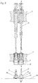
- Figure 8 shows a bushing 16 with the respective case 2 inserted, housed in a corresponding seat 12 with a certain freedom of movement given by the difference between the outer diameter of the bushing d, measured at its annular groove 18, and the internal dimension D of the seat 12.
- a centering cylinder 8 is provided, supported by said second operating beam 7, coaxial to a working tool 6, provided even further above and supported by said first operating beam 5.
- Said centering cylinder 8 and said working tool 6 have their respective vertical axes y, z coinciding, while it is not yet strictly necessary for axis x of the case 2 underneath to do so.
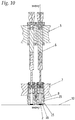
- Figure 9 shows the delicate phase of centering the case 2.
- Said second operating beam 5 controlled by the control unit and moved by the corresponding motor means, is vertically lowered until the centering cylinder 8 touches the bushing 16 underneath.
- the case 2 is ready to be filled with the internal accessories and/or processed by the corresponding working tool 6 above.
- the conveyor guide 11 can then translate horizontally to a position along the trajectory of the race 10, positioning the bushing 16 and the processed case 2 below another adjacent work station.
Landscapes
- Engineering & Computer Science (AREA)
- Manufacturing & Machinery (AREA)
- General Engineering & Computer Science (AREA)
- Automatic Assembly (AREA)
- Control And Other Processes For Unpacking Of Materials (AREA)
Claims (6)
- Eine Lademaschine (1) für Patronen mit einem Metallgehäuse (2), umfassend:- eine Rahmenstruktur (3);- Einspeisevorrichtungen (4) für eine Vielzahl von Gehäusen (2) mit einem gegebenen Kaliber (c) und einer sich in Längsrichtung erstreckenden Achse (x);- Einspeisevorrichtungen für eine Vielzahl von spitzbogenförmige Kugeln, die als Geschoss fungieren können;- Einspeisevorrichtungen für Schießpulver;- einen ersten Betriebsarm (5) mit einer abwechselnden vertikalen Verschiebungsbewegung, versehen mit Arbeitswerkzeugen (6) mit einer vertikalen Achse (y), die zum Laden der besagten Gehäuse (2) geeignet ist;- Einspeise- und Fördervorrichtungen der besagten Gehäuse (2) während des Ladevorgangs;- Vorrichtungen zum Auswerfen der geladenen Patronen;- Motorvorrichtungen (M) zur Aktivierung der kinematischen Mechanismen;- eine Steuereinheit (24);wobei die besagten Einspeisevorrichtungen der besagten Gehäuse (2) Folgendes umfassen:- eine Laufbahn (10), die geeignet ist, um die besagten Gehäuse (2) in einer gegebenen Richtung zu befördern und die Einspeisung zuzulassen;- eine Förderbandführung (11), die parallel zu der besagten Laufbahn (10) angeordnet und kammartig geformt ist, um eine Vielzahl von Sitzen (12) zu definieren, geeignet, die besagten Gehäuse (2) aufzunehmen und sie entlang der besagten Laufbahn (10) zu transportieren, um sie entsprechend den verschiedenen Füllschritten unter entsprechenden Arbeitswerkzeugen (6) zu positionieren,dadurch gekennzeichnet, dass:- die besagte Förderbandführung (11) eine Vielzahl von Buchsen (16) umfasst, wobei jede Buchse (16) mindestens eine erste konische Oberfläche (21) und ein Loch (17) umfasst, das zur Aufnahme eines der besagten Gehäuse (2) geeignet ist und in einem der besagten Sitze (12) untergebracht ist, wobei der Außendurchmesser (D) der besagten Buchse (16) kleiner ist als die Innenabmessung (d) der besagten Sitze (12), um eine minimale Bewegungsfreiheit zwischen Buchse (16) und jeweiligem Sitz (12) zu gewährleisten;- die besagte Maschine (1) einen zweiten Betriebsarm (7) mit einer alternierenden vertikalen Translationsbewegung aufweist, die mit der alternierenden vertikalen Translationsbewegung des besagten ersten Betriebsarm (5) koordiniert ist, wobei der besagte zweite Betriebsarm (7) mit einer Vielzahl von hohlen Zentrierzylindern (8) mit einer vertikalen Achse (z) und einer zweiten konischen Oberfläche (23) in ihrem Inneren versehen ist, wobei jeder Zentrierzylinder (8) so angeordnet ist, dass seine vertikale Achse (z) mit der vertikalen Achse (y) eines der besagten Werkzeuge (6) übereinstimmt,wobei die Kopplung zwischen der ersten konischen Oberfläche (21) jeder Buchse (16) und der zweiten konischen Oberfläche (23) eines entsprechenden Zentrierzylinders (8) eine Verschiebung der besagten Buchse (16) in dem besagten Sitz (12) und damit eine Verschiebung des in der besagten Buchse (16) aufgenommenen Gehäuses (2) bewirkt, um eine Koaxialität zwischen der Längsachse (x) des besagten Gehäuses (2) und der vertikalen Achse (z) des besagten Zentrierzylinders (8) zu erhalten.
- Eine Lademaschine (1) gemäß Anspruch 1, dadurch gekennzeichnet, dass die besagten Buchsen (16) mindestens einen radialen Schnitt (22) aufweisen, der geeignet ist, um ihre elastische Verformung während des Einsetzens des Gehäuses (2) in ihr Loch (17) zu ermöglichen.
- Eine Lademaschine (1) gemäß Anspruch 1, dadurch gekennzeichnet, dass die besagte Förderbandführung (11) Mittel zum reversiblen Halten der besagten Buchsen (16) in den besagten Sitzen (12) umfasst, so dass sie in Abhängigkeit vom Kaliber (c) der zu ladenden Gehäuse (2) entfernt und ausgetauscht werden können.
- Eine Lademaschine (1) gemäß Anspruch 3, dadurch gekennzeichnet, dass jeder Sitz (12) U-förmig ist und die besagten Haltemittel Bolzen (19) aufweisen, deren Kopf (19') zumindest teilweise in den Raum (d) eingreift, der sich zwischen den Armen (14) jedes U-förmigen Sitzes (12) befindet.
- Eine Lademaschine (1) gemäß Anspruch 4, dadurch gekennzeichnet, dass die besagte Buchse (16) eine ringförmige Nut (18) umfasst, die auf ihrer Außenfläche erzielt wurde, und die Arme (14) des besagten U-förmigen Sitzes (12) geeignet sind, dass sie in die besagte Nut (18) eingreifen, um die besagte Buchse (16) zu halten.
- Eine Lademaschine (1) gemäß Anspruch 1, dadurch gekennzeichnet, dass die besagte Rahmenstruktur (3) vertikale Führungen (9) umfasst, die gleichzeitig von dem besagten ersten (5) und dem besagten zweiten (7) Betriebsarm in Anspruch genommen werden, so dass die Ebenen, zu denen die besagten Arme gehören, während der Translationsbewegung vollkommen parallel zueinander bleiben.
Applications Claiming Priority (2)
| Application Number | Priority Date | Filing Date | Title |
|---|---|---|---|
| ITUB2015A005750A ITUB20155750A1 (it) | 2015-11-19 | 2015-11-19 | Macchina caricatrice per cartucce a bossolo metallico |
| PCT/IT2016/000273 WO2017085751A1 (en) | 2015-11-19 | 2016-11-18 | Loading machine for cartridges with a metal case |
Publications (2)
| Publication Number | Publication Date |
|---|---|
| EP3377845A1 EP3377845A1 (de) | 2018-09-26 |
| EP3377845B1 true EP3377845B1 (de) | 2019-12-18 |
Family
ID=55485133
Family Applications (1)
| Application Number | Title | Priority Date | Filing Date |
|---|---|---|---|
| EP16836117.8A Active EP3377845B1 (de) | 2015-11-19 | 2016-11-18 | Beladungsmaschine für patronen mit einem metallgehäuse |
Country Status (4)
| Country | Link |
|---|---|
| US (1) | US10443994B2 (de) |
| EP (1) | EP3377845B1 (de) |
| IT (1) | ITUB20155750A1 (de) |
| WO (1) | WO2017085751A1 (de) |
Families Citing this family (8)
| Publication number | Priority date | Publication date | Assignee | Title |
|---|---|---|---|---|
| US11085746B2 (en) | 2018-05-30 | 2021-08-10 | Dillon Precision Products, Inc. | Rotary-drive ammunition reloading systems with discontinuous stroke speed |
| US12228385B2 (en) | 2014-09-22 | 2025-02-18 | Dillon Precision Products, Inc. | Ammunition reloading systems and methods |
| US11085747B2 (en) | 2014-09-22 | 2021-08-10 | Dillon Precision Products, Inc. | Ammunition reloading systems and methods |
| KR20180125152A (ko) * | 2016-03-03 | 2018-11-22 | 프리츠 베르너 인더스트리에-아우스뤼스툰겐 게엠바하 | 피드백 조립 제어부를 이용한 자동화된 점진적 탄약, 특히 카트리지, 조립 장치 및 방법 |
| WO2018173087A1 (en) * | 2017-03-22 | 2018-09-27 | E.M.G. S.R.L. | Loading machine for cartridges with a metal case |
| US11768064B2 (en) * | 2020-01-15 | 2023-09-26 | Bitterroot Tool & Machine, Inc. | Table top priming machine for small caliber ammunition |
| DE102022119665A1 (de) | 2022-08-04 | 2024-02-15 | Ruag Ammotec Ag | Werkstückträger für eine automatisierte Fertigungslinie für Munition mit wenigstens zwei Munitionsteilen |
| CN116379848A (zh) * | 2022-12-15 | 2023-07-04 | 合肥海得智能科技有限公司 | 一种射孔弹本质安全智能制造系统 |
Family Cites Families (55)
| Publication number | Priority date | Publication date | Assignee | Title |
|---|---|---|---|---|
| US2371126A (en) * | 1945-03-13 | Apparatus for feeding-articles from | ||
| US454578A (en) * | 1891-06-23 | Cartridge-loader | ||
| US2350181A (en) * | 1942-03-30 | 1944-05-30 | Triumph Explosives Inc | Loading apparatus |
| US2376293A (en) * | 1943-01-21 | 1945-05-15 | Pneumatic Scale Corp | Bullet handling apparatus |
| US2818964A (en) * | 1955-05-31 | 1958-01-07 | Canadian Arsenals Ltd | Apparatus for the controlled feeding of cartridge cases and other articles |
| US3153976A (en) * | 1961-10-17 | 1964-10-27 | Lowell E Linder | Ammunition reloading apparatus |
| US3450000A (en) * | 1968-03-15 | 1969-06-17 | Ponsness Warren Inc | Apparatus for reconditioning and reloading shotgun shells |
| US3580127A (en) * | 1968-08-19 | 1971-05-25 | Richard J Lee | Cartridge case reloading |
| US3610090A (en) * | 1969-10-27 | 1971-10-05 | Lyle S Corcoran | Casing feeding apparatus for ammunition reloading |
| US3602084A (en) * | 1970-01-26 | 1971-08-31 | Lyle S Corcoran | Bullet feed mechanism with automatically released holding collet |
| US3732774A (en) * | 1971-05-05 | 1973-05-15 | T Griffin | Automatic reloading apparatus and shotgun shell drive means therefor |
| US3788035A (en) * | 1972-06-21 | 1974-01-29 | Container Corp | Caulking cartridge filling and seaming machine |
| US3771411A (en) * | 1972-07-03 | 1973-11-13 | Ponsness Warren | Shotgun cartridge loading machine |
| US3796127A (en) * | 1972-11-01 | 1974-03-12 | Pacific Gun Sight Co | Shell reloader with improved sizing die |
| US3857319A (en) * | 1973-05-29 | 1974-12-31 | A Welch | Small arms cartridge reloader press |
| US3916758A (en) * | 1973-06-15 | 1975-11-04 | Clifford L Ashbrook | Universal cartridge holder |
| US4020737A (en) * | 1973-07-26 | 1977-05-03 | Ranson Charles R | Cartridge loading machine |
| US4078472A (en) * | 1976-04-12 | 1978-03-14 | Simpson Frank H | Shotgun shell reloading tool |
| US4292877A (en) * | 1976-10-21 | 1981-10-06 | Lee Richard J | Ammunition loader with improved charge bar |
| US4312438A (en) * | 1978-03-27 | 1982-01-26 | Vatsvog Marlo K | Bullet alignment apparatus |
| US4328735A (en) * | 1979-01-31 | 1982-05-11 | Allen Johnnie D | Progressive shotshell reloading |
| US4331063A (en) * | 1980-06-02 | 1982-05-25 | Schaenzer Gordon N | Cartridge reloading press |
| US4425833A (en) * | 1982-08-27 | 1984-01-17 | Gopher Shooter's Supply Company, Incorporated | Cartridge case holder apparatus |
| US4475435A (en) * | 1983-02-25 | 1984-10-09 | Mantel Machine Products, Inc. | In line bullet feeder |
| US4522102A (en) * | 1983-06-27 | 1985-06-11 | Pickens Ralph D | Semi-automatic cartridge reloading machine |
| US4573392A (en) * | 1984-09-10 | 1986-03-04 | Mantel Machine Products, Inc. | In-line bullet feeder |
| DE3536672A1 (de) * | 1985-10-15 | 1987-04-16 | Krauss Maffei Ag | Vorrichtung zur zentrierenden halterung von munition in einem munitionsaufnehmer |
| US4852451A (en) * | 1988-11-02 | 1989-08-01 | Rogers Ronald O | Powder level sensing device |
| DE3939295A1 (de) * | 1989-11-28 | 1991-05-29 | Rheinmetall Gmbh | Verfahren und vorrichtung zur herstellung von grosskalibriger munition |
| US5024135A (en) * | 1989-12-15 | 1991-06-18 | Blount, Inc. | Multi-station cartridge reloading press with controlled powder dispensing |
| US5177315A (en) * | 1992-03-02 | 1993-01-05 | Terry Burgess | Replacement primer feeder for shell reloading machines |
| US5179243A (en) * | 1992-06-04 | 1993-01-12 | George Schroeder | Ammunition assembly device |
| US5335578A (en) * | 1993-07-13 | 1994-08-09 | Lorden Paul R | Automatic shell feeding attachment for a reloading machine |
| US5507132A (en) * | 1993-12-10 | 1996-04-16 | General Mills, Inc. | Apparatus for opening microwave popcorn bags |
| US5719348A (en) * | 1996-01-16 | 1998-02-17 | Blount, Inc. | Component holder for cartridge reloading |
| US5763810A (en) * | 1996-07-17 | 1998-06-09 | Lee Precision, Inc. | Automatic bullet feeder |
| US5900574A (en) * | 1997-09-19 | 1999-05-04 | Hart; Larry L. | Reloading apparatus which automatically sets a bullet into the mouth of a casing |
| US6041687A (en) * | 1998-05-05 | 2000-03-28 | Fowler; Malcolm | Automated bullet feeding mechanism for use with a shell reloader |
| US20020121184A1 (en) * | 2001-03-02 | 2002-09-05 | Fowler Malcolm R. | Automatic bullet feeding mechanism |
| US6739111B2 (en) * | 2001-09-06 | 2004-05-25 | The Boeing Company | Automated filling machine and associated method |
| US6772668B2 (en) * | 2002-08-07 | 2004-08-10 | Alliant Techsystems, Inc. | Ammunition reloading apparatus with feed mechanism |
| ITMI20022565A1 (it) * | 2002-12-04 | 2004-06-05 | Amut Spa | Macchina per la disposizione ordinata di articoli impilabili |
| ITBO20040008U1 (it) * | 2004-02-03 | 2004-05-03 | Tonazzi S R L | Macchina per il riempimento e la chiusura di tubetti |
| US7549364B2 (en) * | 2006-08-29 | 2009-06-23 | Koskela Richard A | Shell loading system |
| US7694618B1 (en) * | 2006-10-30 | 2010-04-13 | Lee Precision, Inc. | Ammunition primer installation device |
| US7552668B1 (en) * | 2007-02-05 | 2009-06-30 | Gonzalez Xavier G | Rotary bullet feeder and toolhead assemblies for use with progressive cartridge reloading machines |
| US7743692B2 (en) * | 2008-01-02 | 2010-06-29 | Jackson Jason S | Shell case length limit alarm |
| US8276494B2 (en) * | 2009-10-08 | 2012-10-02 | Hornady Manufacturing Company | Bullet feed die assembly |
| US8820206B2 (en) * | 2011-05-09 | 2014-09-02 | Victor Javier Coma Asensio | Bullet projectile and case feeding device |
| US8683906B2 (en) * | 2011-12-06 | 2014-04-01 | Dixon Automatic Tool, Inc. | Ammunition loader |
| US10907943B2 (en) * | 2013-03-15 | 2021-02-02 | Cybernet Systems Corp. | Integrated polymer and metal case ammunition manufacturing system and method |
| US9360284B1 (en) * | 2013-03-15 | 2016-06-07 | Vista Outdoor Operations Llc | Manufacturing process to produce metalurgically programmed terminal performance projectiles |
| ITCR20130018A1 (it) * | 2013-07-19 | 2015-01-20 | E M G Srl | Macchina caricatrice per cartucce con sistema rapido di cambio calibro |
| EP3032215B1 (de) * | 2014-12-12 | 2017-04-26 | Mark 7 Reloading LLC | Verbesserungen beim Aufladen von Kartuschen |
| US9846018B1 (en) * | 2016-11-04 | 2017-12-19 | Mayville Engineering Company Inc. | Self-adjusting shell holder for metallic cartridge reloading presses |
-
2015
- 2015-11-19 IT ITUB2015A005750A patent/ITUB20155750A1/it unknown
-
2016
- 2016-11-18 WO PCT/IT2016/000273 patent/WO2017085751A1/en not_active Ceased
- 2016-11-18 EP EP16836117.8A patent/EP3377845B1/de active Active
- 2016-11-18 US US15/776,740 patent/US10443994B2/en active Active
Non-Patent Citations (1)
| Title |
|---|
| None * |
Also Published As
| Publication number | Publication date |
|---|---|
| ITUB20155750A1 (it) | 2017-05-19 |
| US10443994B2 (en) | 2019-10-15 |
| EP3377845A1 (de) | 2018-09-26 |
| US20180335286A1 (en) | 2018-11-22 |
| WO2017085751A1 (en) | 2017-05-26 |
Similar Documents
| Publication | Publication Date | Title |
|---|---|---|
| US10443994B2 (en) | Loading machine for cartridges with a metal case | |
| EP2437913B1 (de) | Vereinzelungsführung für eine zufuhrvorrichtung für ein verbindungselement | |
| EP2864072B1 (de) | Vorrichtung zum zuführen von stangen zu einer werkzeugmaschine | |
| US5366334A (en) | Loading device for sequential loading of bars in machine tools | |
| CN101817054B (zh) | 一种凹模回转镦锻机及工作方法 | |
| US10393458B2 (en) | Axially relieved bolt face for blowback bolt firearms | |
| RU2730350C2 (ru) | Устройство и способ извлечения и выгрузки обрезных концов прутков из механического станка | |
| CN103273366A (zh) | 轴类全自动数控机床 | |
| CN105371708A (zh) | 烟花内筒生产线 | |
| CN104741965B (zh) | 小直径管坯自动上下料装置 | |
| US20040025677A1 (en) | Ammunition reloading apparatus with case holder and resizing die | |
| EP2827092B1 (de) | Vorrichtung zum Laden einer Hulse mit schnellen Anpassung des Kalibers | |
| EP3404353B1 (de) | Vorrichtung und methode zum entfernen von zündhütchens aus patronenhülsen | |
| CN112158581A (zh) | 一种打火机自动插盘、装盘装置 | |
| CN210997372U (zh) | 一种接杆钢珠弹簧全自动铆合机 | |
| US3239079A (en) | Work feeder for machine tool | |
| US2821886A (en) | Feeding mechanism for automatic firearm | |
| US10228203B2 (en) | Case discharge device | |
| CN112894312A (zh) | 一种接杆钢珠弹簧全自动铆合机 | |
| US10809046B2 (en) | Loading machine for cartridges with a metal case | |
| US351747A (en) | dimon | |
| CN108672723B (zh) | 齿圈类零件自动加工设备及方法 | |
| RU85627U1 (ru) | Устройство для снятия медного ведущего пояска с корпусов снарядов | |
| US20260138191A1 (en) | Turning machine tool | |
| US2242169A (en) | Automatic machine tool |
Legal Events
| Date | Code | Title | Description |
|---|---|---|---|
| STAA | Information on the status of an ep patent application or granted ep patent |
Free format text: STATUS: UNKNOWN |
|
| STAA | Information on the status of an ep patent application or granted ep patent |
Free format text: STATUS: THE INTERNATIONAL PUBLICATION HAS BEEN MADE |
|
| PUAI | Public reference made under article 153(3) epc to a published international application that has entered the european phase |
Free format text: ORIGINAL CODE: 0009012 |
|
| STAA | Information on the status of an ep patent application or granted ep patent |
Free format text: STATUS: REQUEST FOR EXAMINATION WAS MADE |
|
| 17P | Request for examination filed |
Effective date: 20180606 |
|
| AK | Designated contracting states |
Kind code of ref document: A1 Designated state(s): AL AT BE BG CH CY CZ DE DK EE ES FI FR GB GR HR HU IE IS IT LI LT LU LV MC MK MT NL NO PL PT RO RS SE SI SK SM TR |
|
| AX | Request for extension of the european patent |
Extension state: BA ME |
|
| DAV | Request for validation of the european patent (deleted) | ||
| DAX | Request for extension of the european patent (deleted) | ||
| GRAP | Despatch of communication of intention to grant a patent |
Free format text: ORIGINAL CODE: EPIDOSNIGR1 |
|
| STAA | Information on the status of an ep patent application or granted ep patent |
Free format text: STATUS: GRANT OF PATENT IS INTENDED |
|
| INTG | Intention to grant announced |
Effective date: 20190702 |
|
| GRAS | Grant fee paid |
Free format text: ORIGINAL CODE: EPIDOSNIGR3 |
|
| GRAA | (expected) grant |
Free format text: ORIGINAL CODE: 0009210 |
|
| STAA | Information on the status of an ep patent application or granted ep patent |
Free format text: STATUS: THE PATENT HAS BEEN GRANTED |
|
| AK | Designated contracting states |
Kind code of ref document: B1 Designated state(s): AL AT BE BG CH CY CZ DE DK EE ES FI FR GB GR HR HU IE IS IT LI LT LU LV MC MK MT NL NO PL PT RO RS SE SI SK SM TR |
|
| REG | Reference to a national code |
Ref country code: CH Ref legal event code: EP |
|
| REG | Reference to a national code |
Ref country code: IE Ref legal event code: FG4D |
|
| REG | Reference to a national code |
Ref country code: DE Ref legal event code: R096 Ref document number: 602016026614 Country of ref document: DE |
|
| REG | Reference to a national code |
Ref country code: AT Ref legal event code: REF Ref document number: 1215079 Country of ref document: AT Kind code of ref document: T Effective date: 20200115 |
|
| REG | Reference to a national code |
Ref country code: NL Ref legal event code: MP Effective date: 20191218 |
|
| PG25 | Lapsed in a contracting state [announced via postgrant information from national office to epo] |
Ref country code: BG Free format text: LAPSE BECAUSE OF FAILURE TO SUBMIT A TRANSLATION OF THE DESCRIPTION OR TO PAY THE FEE WITHIN THE PRESCRIBED TIME-LIMIT Effective date: 20200318 Ref country code: FI Free format text: LAPSE BECAUSE OF FAILURE TO SUBMIT A TRANSLATION OF THE DESCRIPTION OR TO PAY THE FEE WITHIN THE PRESCRIBED TIME-LIMIT Effective date: 20191218 Ref country code: GR Free format text: LAPSE BECAUSE OF FAILURE TO SUBMIT A TRANSLATION OF THE DESCRIPTION OR TO PAY THE FEE WITHIN THE PRESCRIBED TIME-LIMIT Effective date: 20200319 Ref country code: NO Free format text: LAPSE BECAUSE OF FAILURE TO SUBMIT A TRANSLATION OF THE DESCRIPTION OR TO PAY THE FEE WITHIN THE PRESCRIBED TIME-LIMIT Effective date: 20200318 Ref country code: LV Free format text: LAPSE BECAUSE OF FAILURE TO SUBMIT A TRANSLATION OF THE DESCRIPTION OR TO PAY THE FEE WITHIN THE PRESCRIBED TIME-LIMIT Effective date: 20191218 Ref country code: SE Free format text: LAPSE BECAUSE OF FAILURE TO SUBMIT A TRANSLATION OF THE DESCRIPTION OR TO PAY THE FEE WITHIN THE PRESCRIBED TIME-LIMIT Effective date: 20191218 Ref country code: LT Free format text: LAPSE BECAUSE OF FAILURE TO SUBMIT A TRANSLATION OF THE DESCRIPTION OR TO PAY THE FEE WITHIN THE PRESCRIBED TIME-LIMIT Effective date: 20191218 |
|
| REG | Reference to a national code |
Ref country code: LT Ref legal event code: MG4D |
|
| PG25 | Lapsed in a contracting state [announced via postgrant information from national office to epo] |
Ref country code: HR Free format text: LAPSE BECAUSE OF FAILURE TO SUBMIT A TRANSLATION OF THE DESCRIPTION OR TO PAY THE FEE WITHIN THE PRESCRIBED TIME-LIMIT Effective date: 20191218 Ref country code: RS Free format text: LAPSE BECAUSE OF FAILURE TO SUBMIT A TRANSLATION OF THE DESCRIPTION OR TO PAY THE FEE WITHIN THE PRESCRIBED TIME-LIMIT Effective date: 20191218 |
|
| PG25 | Lapsed in a contracting state [announced via postgrant information from national office to epo] |
Ref country code: AL Free format text: LAPSE BECAUSE OF FAILURE TO SUBMIT A TRANSLATION OF THE DESCRIPTION OR TO PAY THE FEE WITHIN THE PRESCRIBED TIME-LIMIT Effective date: 20191218 |
|
| PG25 | Lapsed in a contracting state [announced via postgrant information from national office to epo] |
Ref country code: NL Free format text: LAPSE BECAUSE OF FAILURE TO SUBMIT A TRANSLATION OF THE DESCRIPTION OR TO PAY THE FEE WITHIN THE PRESCRIBED TIME-LIMIT Effective date: 20191218 Ref country code: EE Free format text: LAPSE BECAUSE OF FAILURE TO SUBMIT A TRANSLATION OF THE DESCRIPTION OR TO PAY THE FEE WITHIN THE PRESCRIBED TIME-LIMIT Effective date: 20191218 Ref country code: CZ Free format text: LAPSE BECAUSE OF FAILURE TO SUBMIT A TRANSLATION OF THE DESCRIPTION OR TO PAY THE FEE WITHIN THE PRESCRIBED TIME-LIMIT Effective date: 20191218 Ref country code: PT Free format text: LAPSE BECAUSE OF FAILURE TO SUBMIT A TRANSLATION OF THE DESCRIPTION OR TO PAY THE FEE WITHIN THE PRESCRIBED TIME-LIMIT Effective date: 20200513 Ref country code: RO Free format text: LAPSE BECAUSE OF FAILURE TO SUBMIT A TRANSLATION OF THE DESCRIPTION OR TO PAY THE FEE WITHIN THE PRESCRIBED TIME-LIMIT Effective date: 20191218 |
|
| PG25 | Lapsed in a contracting state [announced via postgrant information from national office to epo] |
Ref country code: SM Free format text: LAPSE BECAUSE OF FAILURE TO SUBMIT A TRANSLATION OF THE DESCRIPTION OR TO PAY THE FEE WITHIN THE PRESCRIBED TIME-LIMIT Effective date: 20191218 Ref country code: IS Free format text: LAPSE BECAUSE OF FAILURE TO SUBMIT A TRANSLATION OF THE DESCRIPTION OR TO PAY THE FEE WITHIN THE PRESCRIBED TIME-LIMIT Effective date: 20200418 Ref country code: SK Free format text: LAPSE BECAUSE OF FAILURE TO SUBMIT A TRANSLATION OF THE DESCRIPTION OR TO PAY THE FEE WITHIN THE PRESCRIBED TIME-LIMIT Effective date: 20191218 |
|
| REG | Reference to a national code |
Ref country code: DE Ref legal event code: R097 Ref document number: 602016026614 Country of ref document: DE |
|
| REG | Reference to a national code |
Ref country code: AT Ref legal event code: MK05 Ref document number: 1215079 Country of ref document: AT Kind code of ref document: T Effective date: 20191218 |
|
| PLBE | No opposition filed within time limit |
Free format text: ORIGINAL CODE: 0009261 |
|
| STAA | Information on the status of an ep patent application or granted ep patent |
Free format text: STATUS: NO OPPOSITION FILED WITHIN TIME LIMIT |
|
| PG25 | Lapsed in a contracting state [announced via postgrant information from national office to epo] |
Ref country code: DK Free format text: LAPSE BECAUSE OF FAILURE TO SUBMIT A TRANSLATION OF THE DESCRIPTION OR TO PAY THE FEE WITHIN THE PRESCRIBED TIME-LIMIT Effective date: 20191218 Ref country code: ES Free format text: LAPSE BECAUSE OF FAILURE TO SUBMIT A TRANSLATION OF THE DESCRIPTION OR TO PAY THE FEE WITHIN THE PRESCRIBED TIME-LIMIT Effective date: 20191218 |
|
| 26N | No opposition filed |
Effective date: 20200921 |
|
| PG25 | Lapsed in a contracting state [announced via postgrant information from national office to epo] |
Ref country code: AT Free format text: LAPSE BECAUSE OF FAILURE TO SUBMIT A TRANSLATION OF THE DESCRIPTION OR TO PAY THE FEE WITHIN THE PRESCRIBED TIME-LIMIT Effective date: 20191218 Ref country code: SI Free format text: LAPSE BECAUSE OF FAILURE TO SUBMIT A TRANSLATION OF THE DESCRIPTION OR TO PAY THE FEE WITHIN THE PRESCRIBED TIME-LIMIT Effective date: 20191218 |
|
| PG25 | Lapsed in a contracting state [announced via postgrant information from national office to epo] |
Ref country code: IT Free format text: LAPSE BECAUSE OF FAILURE TO SUBMIT A TRANSLATION OF THE DESCRIPTION OR TO PAY THE FEE WITHIN THE PRESCRIBED TIME-LIMIT Effective date: 20191218 |
|
| PG25 | Lapsed in a contracting state [announced via postgrant information from national office to epo] |
Ref country code: PL Free format text: LAPSE BECAUSE OF FAILURE TO SUBMIT A TRANSLATION OF THE DESCRIPTION OR TO PAY THE FEE WITHIN THE PRESCRIBED TIME-LIMIT Effective date: 20191218 |
|
| REG | Reference to a national code |
Ref country code: DE Ref legal event code: R119 Ref document number: 602016026614 Country of ref document: DE |
|
| PG25 | Lapsed in a contracting state [announced via postgrant information from national office to epo] |
Ref country code: MC Free format text: LAPSE BECAUSE OF FAILURE TO SUBMIT A TRANSLATION OF THE DESCRIPTION OR TO PAY THE FEE WITHIN THE PRESCRIBED TIME-LIMIT Effective date: 20191218 |
|
| REG | Reference to a national code |
Ref country code: CH Ref legal event code: PL |
|
| GBPC | Gb: european patent ceased through non-payment of renewal fee |
Effective date: 20201118 |
|
| PG25 | Lapsed in a contracting state [announced via postgrant information from national office to epo] |
Ref country code: LU Free format text: LAPSE BECAUSE OF NON-PAYMENT OF DUE FEES Effective date: 20201118 |
|
| PG25 | Lapsed in a contracting state [announced via postgrant information from national office to epo] |
Ref country code: LI Free format text: LAPSE BECAUSE OF NON-PAYMENT OF DUE FEES Effective date: 20201130 Ref country code: CH Free format text: LAPSE BECAUSE OF NON-PAYMENT OF DUE FEES Effective date: 20201130 |
|
| PG25 | Lapsed in a contracting state [announced via postgrant information from national office to epo] |
Ref country code: IE Free format text: LAPSE BECAUSE OF NON-PAYMENT OF DUE FEES Effective date: 20201118 Ref country code: FR Free format text: LAPSE BECAUSE OF NON-PAYMENT OF DUE FEES Effective date: 20201130 |
|
| PG25 | Lapsed in a contracting state [announced via postgrant information from national office to epo] |
Ref country code: GB Free format text: LAPSE BECAUSE OF NON-PAYMENT OF DUE FEES Effective date: 20201118 Ref country code: DE Free format text: LAPSE BECAUSE OF NON-PAYMENT OF DUE FEES Effective date: 20210601 |
|
| PG25 | Lapsed in a contracting state [announced via postgrant information from national office to epo] |
Ref country code: MT Free format text: LAPSE BECAUSE OF FAILURE TO SUBMIT A TRANSLATION OF THE DESCRIPTION OR TO PAY THE FEE WITHIN THE PRESCRIBED TIME-LIMIT Effective date: 20191218 Ref country code: CY Free format text: LAPSE BECAUSE OF FAILURE TO SUBMIT A TRANSLATION OF THE DESCRIPTION OR TO PAY THE FEE WITHIN THE PRESCRIBED TIME-LIMIT Effective date: 20191218 |
|
| PG25 | Lapsed in a contracting state [announced via postgrant information from national office to epo] |
Ref country code: MK Free format text: LAPSE BECAUSE OF FAILURE TO SUBMIT A TRANSLATION OF THE DESCRIPTION OR TO PAY THE FEE WITHIN THE PRESCRIBED TIME-LIMIT Effective date: 20191218 |
|
| P01 | Opt-out of the competence of the unified patent court (upc) registered |
Effective date: 20231213 |
|
| PGFP | Annual fee paid to national office [announced via postgrant information from national office to epo] |
Ref country code: TR Payment date: 20251104 Year of fee payment: 10 Ref country code: BE Payment date: 20251127 Year of fee payment: 10 |