EP2827092B1 - Vorrichtung zum Laden einer Hulse mit schnellen Anpassung des Kalibers - Google Patents
Vorrichtung zum Laden einer Hulse mit schnellen Anpassung des Kalibers Download PDFInfo
- Publication number
- EP2827092B1 EP2827092B1 EP14177140.2A EP14177140A EP2827092B1 EP 2827092 B1 EP2827092 B1 EP 2827092B1 EP 14177140 A EP14177140 A EP 14177140A EP 2827092 B1 EP2827092 B1 EP 2827092B1
- Authority
- EP
- European Patent Office
- Prior art keywords
- cartridges
- race
- bar
- loading machine
- machine
- Prior art date
- Legal status (The legal status is an assumption and is not a legal conclusion. Google has not performed a legal analysis and makes no representation as to the accuracy of the status listed.)
- Active
Links
- 230000008859 change Effects 0.000 title claims description 15
- 125000006850 spacer group Chemical group 0.000 claims description 22
- 238000004519 manufacturing process Methods 0.000 claims description 16
- 230000001105 regulatory effect Effects 0.000 claims description 9
- 230000007246 mechanism Effects 0.000 claims description 5
- 230000000284 resting effect Effects 0.000 claims description 4
- 230000004913 activation Effects 0.000 claims description 3
- 230000002441 reversible effect Effects 0.000 claims description 3
- 230000008901 benefit Effects 0.000 description 4
- 230000009471 action Effects 0.000 description 2
- 238000002360 preparation method Methods 0.000 description 2
- 238000012545 processing Methods 0.000 description 2
- 241000272201 Columbiformes Species 0.000 description 1
- 239000004927 clay Substances 0.000 description 1
- 238000005516 engineering process Methods 0.000 description 1
- 231100001261 hazardous Toxicity 0.000 description 1
- 238000012423 maintenance Methods 0.000 description 1
- 230000007257 malfunction Effects 0.000 description 1
- 238000005259 measurement Methods 0.000 description 1
- 238000000034 method Methods 0.000 description 1
- 230000009467 reduction Effects 0.000 description 1
- 238000012795 verification Methods 0.000 description 1
Images



Classifications
-
- F—MECHANICAL ENGINEERING; LIGHTING; HEATING; WEAPONS; BLASTING
- F42—AMMUNITION; BLASTING
- F42B—EXPLOSIVE CHARGES, e.g. FOR BLASTING, FIREWORKS, AMMUNITION
- F42B33/00—Manufacture of ammunition; Dismantling of ammunition; Apparatus therefor
- F42B33/002—Orienting or guiding means for cartridges or cartridge parts during the manufacturing or packaging process; Feeding cartridge elements to automatic machines
-
- F—MECHANICAL ENGINEERING; LIGHTING; HEATING; WEAPONS; BLASTING
- F42—AMMUNITION; BLASTING
- F42B—EXPLOSIVE CHARGES, e.g. FOR BLASTING, FIREWORKS, AMMUNITION
- F42B33/00—Manufacture of ammunition; Dismantling of ammunition; Apparatus therefor
- F42B33/02—Filling cartridges, missiles, or fuzes; Inserting propellant or explosive charges
Definitions
- the invention concerns the field of cartridge production and loading lines, in particular for cartridges used in the sporting, civil and military sector.
- the invention relates to a cartridge loading machine with quick caliber change system, equipped to receive empty cartridges, fill them with the necessary inner components, seal them and manufacture them.
- cartridge loading machines substantially comprise a frame structure, feed means for empty cartridges, an operating beam that supports ancillary means responsible for loading and in-line processing of said cartridges, feed and conveying means of the cartridges during loading thereof, ejection means for the loaded cartridges.
- cartridge feed and conveying means generally comprise:
- said abutment bar is stably and permanently fastened to said loading machine.
- the geometry of the machine and in particular the mutual distances between the race on which the cartridges travel, the conveyor guide and the abutment bar, are in fact defined with extreme precision and essentially depend on the caliber of the cartridges being produced.
- a same machine can however be designed to produce cartridges of different calibers, for example cal. 12, cal. 16, cal. 20, and therefore, when changing from one caliber to another, it is necessary to vary the positions of the aforesaid components by millimeters, to maintain the axis of the cartridge unchanged with respect to the operating devices and allow correct operation of the machine and kinematic coordination of all the moving parts, thereby preventing undesirable misalignment, above all between empty cartridges and ancillary loading means.
- the invention intends to overcome these limits by producing a loading machine provided with feed and conveying means of the cartridges that speed up and simplify operations to prepare the machine during caliber changes of the cartridges to be manufactured.
- a further aim of the invention is to produce a loading machine that is safe for operators, efficient and productive.
- said shifting means of said abutment bar are automatic.
- said shifting means of said abutment bar comprise a pair of pneumatic cylinders.
- said interchangeable regulating means comprise a plurality of spacers, acting as abutment surface for said bar and having a thickness adequate for the distance to be maintained between said bar and said race.
- said spacers are stably associable with said frame structure by means of reversible fastening means.
- said loading machine comprises housings adapted to receive and retain said spacers in stable position.
- each spacer comprises a foot having dimensions corresponding to the dimensions of said housings, and a body adapted to act as support for said abutment bar, wherein said body has a different thickness with respect to the foot, and said thickness is selected as a function of the distance to be maintained between said bar and said race.
- said conveyor guide comprises a first and a second element, wherein said first element moves with translational motion in transverse direction to the direction of movement of said cartridges and is adapted to act, in cooperation with said abutment bar, as stopping and contact element for said cartridges during loading, and said second element moves with translational and rotational motion and is adapted to shift said cartridges from one operating position to the other, at said ancillary means.
- said first and second element are both provided with a comb-shaped edge facing the cartridges.
- the main advantage of the invention consists in the fact that the shifting means of the conveyor bar and the interchangeable regulating means allow quick and accurate preparation of the machine at each caliber change of the cartridges in production and ensure maximum safety for operators working under the operating beam and for the machine itself and its components.
- a further advantage consists in the possibility of easy access to the inside of the loading machine, in particular in proximity of the feed and conveying means of the cartridges.
- Automation of the shifting means of the abutment bar further simplifies the step to replace the regulating means.
- the structure of the spacers in cooperation with the specific housings provided on the frame and into which they can be inserted, makes them self-centering, stable and acting as perfect support and stop surface for the abutment bar, which thus always remains perfectly aligned with the race of the cartridges and at the correct distance therefrom to take account of the caliber of the cartridges being filled.
- the conveyor guide provided with two superimposed elements with differentiated movement is very advantageous.
- the first element provided with translational motion allows the cartridges to remain even more stable during the loading steps, coming into contact against the abutment bar while the cartridges are stopped, and retracting while the second element translates along the race.
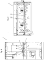
- a loading machine 1 for cartridges 2 generally used for hunting or in the sporting sector, for example for clay pigeon shooting.
- Said machine 1 essentially comprises a frame structure 3 on which there are provided feed means 4 for said empty cartridges 2 having a given caliber c, an operating beam 5 provided with ancillary devices adapted to load said cartridges 2, feed and conveying means 100 of said cartridges 2 during loading thereof, ejection means for the loaded cartridges, motor means 6 for activation of all the kinematic mechanisms and a control unit 7 adapted to monitor all the functions of the machine 1.
- said feed and conveying means 100 of said cartridges 2 comprise:
- said conveyor guide 9 comprises a first 19 and a second 29 element, both having a comb-shaped edge facing the cartridges and at least partly superimposed on one another.
- Said second element 29 instead, moves with translational and rotational motion and is adapted to shift said cartridges 2 on the race from one operating position to the other at the ancillary devices of the operating beam 5, when passing from one filling step to the other of these cartridges, making use of the concave housings arranged along the comb-shaped edge thereof.
- said first 19 and said second 29 element are reversibly associated with the kinematic mechanisms of said loading machine 1, so that, simply by loosening the respective fastening means 16, 17 thereof, it is possible to move said elements 19, 29 away from said race 8, during ordinary maintenance and each caliber change of the cartridges 2 in production.
- said conveyor guide 9 can comprise only the rotating and translating element 29, without the use of the element 19 for stopping the cartridges during the loading steps.
- said feed and conveying means 100 of said cartridges 2 also comprise:
- said shifting means 11 of said abutment bar 10 are automated and can comprise, as for example in the variant shown, a pair of pneumatic cylinders 13, distributed along said bar 10 and operable by means of the control unit 7 provided on the machine 1.
- Said interchangeable regulating means 12 comprise a plurality of pairs of spacers 14 adapted to be inserted between said abutment bar 10 and said race 8, to maintain an appropriate distance therebetween, defined on the basis of the caliber c of the cartridges 2 in production.
- the spacers 14 of each pair in fact, have a suitable thickness s to define the distance to be imposed between said bar 10 and said race 8: at each caliber change of the cartridges 2, this distance must be changed and consequently a further pair of spacers 14 with appropriate thicknesses s is selected.
- Said loading machine 1 comprises housings 15 adapted to retain said spacers 14 in a stable position and, to increase the stability and safety of the feed and conveying means 100 of said cartridges 2, said spacers 14 are also associated with the frame structure 3 of said machine 1 by means of reversible fastening means, for example screws.
- each spacer 14 comprises a foot 14' having dimensions corresponding to the dimensions of said housings 15, and a body 14", against which said abutment bar 10 rests and abuts, having a different thickness s with respect to the foot 14', and said thickness s is selected adequately as a function of the distance to be maintained between said bar 10 and said race 8.
- Figs. 8 and 9 shows, with intentionally deformed proportions, some components of the quick caliber change system, in two possible operating conditions, in particular for cartridges 2 of two different calibers c1, c2.
- the cartridge 2 in production has a smaller caliber c1, for example cal. 12, and consequently, in order for the abutment bar 10 to rest against the cartridge 2, the space between this bar and the race 8 of the cartridges 2 must be minimized and therefore a spacer 14 having a body 14" of limited thickness s1 is used.
- the cartridge 2 in production has a larger caliber c2, for example cal. 20, and therefore the abutment bar 10 must be positioned slightly retracted with respect to the front of the machine 1 and in the condition shown in Fig. 8 : in this case a spacer 14 having a body 14" with increased thickness s2 must be used in order to move the abutment bar 10 slightly farther from the race 8 of the cartridges 2 and offset the increase in caliber c2 of the new cartridge 2 to be manufactured.
- Operation of the loading machine 1 and, in particular, the method of preparing the machine 1 during each caliber change of the cartridges 2 is as follows.
- the operator After stopping the machine, the operator must move the conveyor guide 9 away from the race 8 of the cartridges: standing in front of the machine 1 and loosening the respective fastening means 16, 17, with a simple movement the operator slides the conveyor guide 9 towards him/her, releasing the race 8 from any obstructions.
- the operator selects a pair of spacers 14, evaluating the thicknesses s, s1, s2 of the respective bodies 14" based on the caliber c, c1, c2 of the cartridges 2 to be processed subsequently, and positions them in the housings 15 produced in the frame 3 of the loading machine 1 parallel to the race 8 of the cartridges.
- the operator After fastening the feet 14' of the spacers 14 stably by means of screws, the operator once again operates the pneumatic cylinders 13 so that they push the abutment bar 10 forward, until it rests and abuts against the body 14" of the spacers.
- these operations to prepare the loading machine 1 can be carried out in very short times, in the order of a few minutes, without the requiring verification and alignment instruments, speeding up and considerably simplifying operations that with conventional technologies require hours, as well as skilled personnel and appropriate instruments.
Landscapes
- Engineering & Computer Science (AREA)
- Manufacturing & Machinery (AREA)
- General Engineering & Computer Science (AREA)
- Gear Transmission (AREA)
- Special Conveying (AREA)
- Tyre Moulding (AREA)
Claims (9)
- Eine Lademaschine (1) für Patronen (2) mit schnellem Kaliberwechsel-System, wobei besagte Maschine (1) Folgendes umfasst:- eine Rahmenstruktur (3);- eine Zufuhreinrichtung (4) für eine Vielzahl von leeren Patronen (2), die ein bestimmtes Kaliber (c, c1, c2) besitzen;- einen Betriebsbalken (5) mit Hilfsvorrichtungen, eingerichtet zum Laden und Herstellen von besagten Patronen (2);- eine Vorschub- und Beförderungsvorrichtung (100) für besagte Patronen (2) während ihres Aufladens;- eine Auswurfvorrichtung für die aufgeladenen Patronen;- eine Motorvorrichtung (6) zur Aktivierung der kinematischen Mechanismen;- eine Steuereinheit (7);wobei besagte Vorschub- und Beförderungsvorrichtung (100) von besagten Patronen (2) Folgendes umfasst:- einen Lauf (8), eingerichtet, um die Zufuhr besagter Patronen (2) in eine bestimmte Richtung gemäß einer geradlinigen Bahn zu unterstützen und zu erlauben;- eine Beförderungsführung (9), angeordnet parallel zu besagtem Lauf (8) längs der Seite von diesem, die der Vorderseite der Maschine (1) gegenüberliegt, dazu eingerichtet, besagte Patronen (2) entlang besagtem Lauf (8) zu befördern;- eine Anlagestange (10), parallel zu besagtem Lauf (8) angeordnet, symmetrisch bezüglich besagter Beförderungsführung (9), dazu eingerichtet, als vertikale Stütz- und Anschlagfläche für besagte Patronen (2) in der Produktion zu wirken, dadurch gekennzeichnet, dass besagte Vorschub- und Beförderungsvorrichtung (100) von besagten Patronen (2) auch Folgendes umfasst:- Verlagerungsvorrichtungen (11) von besagter Anlagestange (10) in Querrichtung zur Richtung des Vorschubs besagter Patronen (2);- auswechselbare Regulierungsvorrichtungen (12), so eingerichtet, dass sie dazu beitragen, an besagter Anlagestange (10) anzuliegen, um selektiv einen angemessenen Abstand zwischen besagter Stange (10) und besagtem Lauf (8) als eine Funktion vom Kaliber (c, c1, c2) besagter Patronen (2) zu definieren.
- Die Lademaschine (1) für Patronen (2) gemäß Anspruch 1, gekennzeichnet dadurch, dass besagte Verlagerungsvorrichtungen (11) von besagter Anlagestange (10) automatisch sind.
- Die Lademaschine (1) für Patronen (2) gemäß Anspruch 2, gekennzeichnet dadurch, dass besagte Verlagerungsvorrichtungen (11) von besagter Anlagestange (10) ein Paar pneumatischer Zylinder (13) umfassen.
- Die Lademaschine (1) für Patronen (2) gemäß Anspruch 1, gekennzeichnet dadurch, dass besagte auswechselbare Regulierungsvorrichtungen (12) eine Vielzahl von Abstandhaltern (14) umfassen, die als Anlagefläche besagter Stange (10) dienen und eine Dicke (s, s1, s2) besitzen, die angemessen ist für den Abstand, der zwischen besagter Stange (10) und besagtem Lauf (8) zu bewahren ist.
- Die Lademaschine (1) für Patronen (2) gemäß Anspruch 4, gekennzeichnet dadurch, dass besagte Abstandhalter (14) mit besagter Rahmenstruktur (3) durch reversible Befestigungsvorrichtungen stabil verbunden sind.
- Die Lademaschine (1) für Patronen (2) gemäß den Ansprüchen 4 oder 5, gekennzeichnet dadurch, dass sie Gehäuse (15) umfasst, so eingerichtet, dass sie besagte Abstandhalter (14) in einer stabilen Position aufnehmen und festhalten.
- Die Lademaschine (1) für Patronen (2) gemäß Anspruch 6, gekennzeichnet dadurch, dass jeder Abstandhalter (14) einen Fuß (14'), dessen Maße den Größen besagter Gehäuse (15) entsprechen, und einen Körper (14") umfasst, dazu eingerichtet, als Stütze für besagte Anlagestange (10) zu dienen, wobei besagter Körper (14") eine unterschiedliche Dicke (s, s1, s2) als die des Fußes (14') besitzt, und besagte Dicke (s, s1, s2) als eine Funktion des Abstands, der zwischen besagter Stange (10) und besagtem Lauf (8) bestehen muss, gewählt wird.
- Die Lademaschine (1) für Patronen (2) gemäß Anspruch 1, gekennzeichnet dadurch, dass besagte Beförderungsführung (9) ein erstes (19) und ein zweites (29) Element umfasst, wobei sich besagtes erstes Element (19) mit translatorischer Bewegung quer zur Bewegungsrichtung besagter Patronen (2) bewegt und eingerichtet ist, um zusammen mit besagter Anlagestange (10) als Anschlag- und Kontaktelement für besagte Patronen (2) während der Ladung zu dienen, und sich besagtes zweites Element (29) mit translatorischer und rotierender Bewegung bewegt und eingerichtet ist, um besagte Patronen (2) von einer Betriebsposition zur anderen an besagte Hilfsvorrichtungen zu versetzen.
- Die Lademaschine (1) für Patronen (2) gemäß Anspruch 8, gekennzeichnet dadurch, dass besagtes erstes (19) und zweites (29) Element mit einer den Patronen zugewandten kammartigen Kante versehen sind.
Applications Claiming Priority (1)
| Application Number | Priority Date | Filing Date | Title |
|---|---|---|---|
| IT000018A ITCR20130018A1 (it) | 2013-07-19 | 2013-07-19 | Macchina caricatrice per cartucce con sistema rapido di cambio calibro |
Publications (2)
| Publication Number | Publication Date |
|---|---|
| EP2827092A1 EP2827092A1 (de) | 2015-01-21 |
| EP2827092B1 true EP2827092B1 (de) | 2016-03-23 |
Family
ID=49226294
Family Applications (1)
| Application Number | Title | Priority Date | Filing Date |
|---|---|---|---|
| EP14177140.2A Active EP2827092B1 (de) | 2013-07-19 | 2014-07-15 | Vorrichtung zum Laden einer Hulse mit schnellen Anpassung des Kalibers |
Country Status (2)
| Country | Link |
|---|---|
| EP (1) | EP2827092B1 (de) |
| IT (1) | ITCR20130018A1 (de) |
Families Citing this family (4)
| Publication number | Priority date | Publication date | Assignee | Title |
|---|---|---|---|---|
| ITUB20155750A1 (it) * | 2015-11-19 | 2017-05-19 | E M G Srl | Macchina caricatrice per cartucce a bossolo metallico |
| IT201800003209A1 (it) * | 2018-03-02 | 2019-09-02 | S E P A Snc Di A Ing Mestriner E C | Unità di azionamento di una macchina transfer lineare e macchina transfer lineare per l’assemblaggio di cartucce comprendente tale unità di azionamento |
| CN109596015B (zh) * | 2018-11-26 | 2021-03-02 | 四川石油射孔器材有限责任公司 | 一种可调定量装粘结造粒炸药装置 |
| CN109855484B (zh) * | 2018-11-26 | 2021-07-30 | 四川石油射孔器材有限责任公司 | 一种可调定量装粘结造粒炸药装置、控制系统及控制方法 |
Family Cites Families (3)
| Publication number | Priority date | Publication date | Assignee | Title |
|---|---|---|---|---|
| FR950182A (fr) * | 1947-07-26 | 1949-09-20 | Chargeuse à cartouches de chasse à réglage instantané | |
| US4020737A (en) * | 1973-07-26 | 1977-05-03 | Ranson Charles R | Cartridge loading machine |
| US8683906B2 (en) * | 2011-12-06 | 2014-04-01 | Dixon Automatic Tool, Inc. | Ammunition loader |
-
2013
- 2013-07-19 IT IT000018A patent/ITCR20130018A1/it unknown
-
2014
- 2014-07-15 EP EP14177140.2A patent/EP2827092B1/de active Active
Also Published As
| Publication number | Publication date |
|---|---|
| ITCR20130018A1 (it) | 2015-01-20 |
| EP2827092A1 (de) | 2015-01-21 |
Similar Documents
| Publication | Publication Date | Title |
|---|---|---|
| EP2827092A1 (de) | Vorrichtung zum Laden einer Hulse mit schnellen Anpassung des Kalibers | |
| US12138677B2 (en) | Bending machine for metal sheets | |
| DK3104990T3 (en) | MACHINE FOR BENDING METAL PLATES | |
| KR101576948B1 (ko) | 스트레치 벤딩기용 금형유닛 | |
| EP3603844B1 (de) | Automatische domer-positionierung in einer dosenkörper herstellungsmaschine | |
| CN106180865B (zh) | 一种工件快速切割落料装置 | |
| RU2594571C2 (ru) | Люнет | |
| EP3479943B1 (de) | Trennmaschine zum trennen von profilstangen, insbesondere aus aluminium, leichtmetall, pvc oder dergleichen | |
| EP3377845B1 (de) | Beladungsmaschine für patronen mit einem metallgehäuse | |
| CN102126135A (zh) | 一种金属风扇叶轮自动成型机 | |
| CN108515121A (zh) | 一种全自动弯刀机及其平行双丝杆循环送料机构 | |
| EP2594358B1 (de) | Bearbeitungszentrum mit festem Portal zur Bearbeitung von Holzbalken | |
| KR20180018476A (ko) | 리본 시트 상에서 정밀한 레이저 커팅을 수행하기 위한 방법 및 상기 방법을 수행하기 위한 장치 | |
| CN103009171B (zh) | 一种全自动数控眼镜镜框加工机的送料器 | |
| KR101770569B1 (ko) | 모터 샤프트 이송장치 | |
| WO2017158090A1 (en) | Cartesian machine tool with horizontal slide and cantilevered machining head, and slide carriage for such machine tool | |
| EP4105158B1 (de) | Faltvorrichtung | |
| CN210061294U (zh) | 一种用于半切裁断的冲头、及一种移动式半切裁断机 | |
| CN201950461U (zh) | 一种金属风扇叶轮自动成型机 | |
| CN209156256U (zh) | 一种led管脚自动点胶装置 | |
| CN208600828U (zh) | 一种可移动的双头锯 | |
| EP3308944A1 (de) | Vorrichtung zum thermoformen mit einem längenmesssensor | |
| CN114148010B (zh) | 一种带束层供料架 | |
| EP2998908B1 (de) | Fütterungs- und zählstation für schrot für mit bleitschrot geladen jagdpatronen | |
| US46448A (en) | clarke |
Legal Events
| Date | Code | Title | Description |
|---|---|---|---|
| 17P | Request for examination filed |
Effective date: 20140715 |
|
| AK | Designated contracting states |
Kind code of ref document: A1 Designated state(s): AL AT BE BG CH CY CZ DE DK EE ES FI FR GB GR HR HU IE IS IT LI LT LU LV MC MK MT NL NO PL PT RO RS SE SI SK SM TR |
|
| AX | Request for extension of the european patent |
Extension state: BA ME |
|
| PUAI | Public reference made under article 153(3) epc to a published international application that has entered the european phase |
Free format text: ORIGINAL CODE: 0009012 |
|
| R17P | Request for examination filed (corrected) |
Effective date: 20150715 |
|
| RAX | Requested extension states of the european patent have changed |
Extension state: ME Extension state: BA Payment date: 20150715 |
|
| RBV | Designated contracting states (corrected) |
Designated state(s): AL AT BE BG CH CY CZ DE DK EE ES FI FR GB GR HR HU IE IS IT LI LT LU LV MC MK MT NL NO PL PT RO RS SE SI SK SM TR |
|
| RIC1 | Information provided on ipc code assigned before grant |
Ipc: F42B 33/00 20060101AFI20150803BHEP Ipc: F42B 33/02 20060101ALI20150803BHEP |
|
| GRAP | Despatch of communication of intention to grant a patent |
Free format text: ORIGINAL CODE: EPIDOSNIGR1 |
|
| INTG | Intention to grant announced |
Effective date: 20150925 |
|
| GRAS | Grant fee paid |
Free format text: ORIGINAL CODE: EPIDOSNIGR3 |
|
| GRAA | (expected) grant |
Free format text: ORIGINAL CODE: 0009210 |
|
| AK | Designated contracting states |
Kind code of ref document: B1 Designated state(s): AL AT BE BG CH CY CZ DE DK EE ES FI FR GB GR HR HU IE IS IT LI LT LU LV MC MK MT NL NO PL PT RO RS SE SI SK SM TR |
|
| AX | Request for extension of the european patent |
Extension state: BA |
|
| REG | Reference to a national code |
Ref country code: GB Ref legal event code: FG4D |
|
| REG | Reference to a national code |
Ref country code: CH Ref legal event code: EP |
|
| REG | Reference to a national code |
Ref country code: AT Ref legal event code: REF Ref document number: 783586 Country of ref document: AT Kind code of ref document: T Effective date: 20160415 |
|
| REG | Reference to a national code |
Ref country code: IE Ref legal event code: FG4D |
|
| REG | Reference to a national code |
Ref country code: DE Ref legal event code: R096 Ref document number: 602014001185 Country of ref document: DE |
|
| REG | Reference to a national code |
Ref country code: LT Ref legal event code: MG4D |
|
| REG | Reference to a national code |
Ref country code: NL Ref legal event code: MP Effective date: 20160323 |
|
| PG25 | Lapsed in a contracting state [announced via postgrant information from national office to epo] |
Ref country code: HR Free format text: LAPSE BECAUSE OF FAILURE TO SUBMIT A TRANSLATION OF THE DESCRIPTION OR TO PAY THE FEE WITHIN THE PRESCRIBED TIME-LIMIT Effective date: 20160323 Ref country code: GR Free format text: LAPSE BECAUSE OF FAILURE TO SUBMIT A TRANSLATION OF THE DESCRIPTION OR TO PAY THE FEE WITHIN THE PRESCRIBED TIME-LIMIT Effective date: 20160624 Ref country code: FI Free format text: LAPSE BECAUSE OF FAILURE TO SUBMIT A TRANSLATION OF THE DESCRIPTION OR TO PAY THE FEE WITHIN THE PRESCRIBED TIME-LIMIT Effective date: 20160323 Ref country code: NO Free format text: LAPSE BECAUSE OF FAILURE TO SUBMIT A TRANSLATION OF THE DESCRIPTION OR TO PAY THE FEE WITHIN THE PRESCRIBED TIME-LIMIT Effective date: 20160623 |
|
| REG | Reference to a national code |
Ref country code: AT Ref legal event code: MK05 Ref document number: 783586 Country of ref document: AT Kind code of ref document: T Effective date: 20160323 |
|
| PG25 | Lapsed in a contracting state [announced via postgrant information from national office to epo] |
Ref country code: SE Free format text: LAPSE BECAUSE OF FAILURE TO SUBMIT A TRANSLATION OF THE DESCRIPTION OR TO PAY THE FEE WITHIN THE PRESCRIBED TIME-LIMIT Effective date: 20160323 Ref country code: NL Free format text: LAPSE BECAUSE OF FAILURE TO SUBMIT A TRANSLATION OF THE DESCRIPTION OR TO PAY THE FEE WITHIN THE PRESCRIBED TIME-LIMIT Effective date: 20160323 Ref country code: LT Free format text: LAPSE BECAUSE OF FAILURE TO SUBMIT A TRANSLATION OF THE DESCRIPTION OR TO PAY THE FEE WITHIN THE PRESCRIBED TIME-LIMIT Effective date: 20160323 Ref country code: RS Free format text: LAPSE BECAUSE OF FAILURE TO SUBMIT A TRANSLATION OF THE DESCRIPTION OR TO PAY THE FEE WITHIN THE PRESCRIBED TIME-LIMIT Effective date: 20160323 Ref country code: LV Free format text: LAPSE BECAUSE OF FAILURE TO SUBMIT A TRANSLATION OF THE DESCRIPTION OR TO PAY THE FEE WITHIN THE PRESCRIBED TIME-LIMIT Effective date: 20160323 |
|
| PG25 | Lapsed in a contracting state [announced via postgrant information from national office to epo] |
Ref country code: PL Free format text: LAPSE BECAUSE OF FAILURE TO SUBMIT A TRANSLATION OF THE DESCRIPTION OR TO PAY THE FEE WITHIN THE PRESCRIBED TIME-LIMIT Effective date: 20160323 Ref country code: IS Free format text: LAPSE BECAUSE OF FAILURE TO SUBMIT A TRANSLATION OF THE DESCRIPTION OR TO PAY THE FEE WITHIN THE PRESCRIBED TIME-LIMIT Effective date: 20160723 Ref country code: EE Free format text: LAPSE BECAUSE OF FAILURE TO SUBMIT A TRANSLATION OF THE DESCRIPTION OR TO PAY THE FEE WITHIN THE PRESCRIBED TIME-LIMIT Effective date: 20160323 |
|
| PG25 | Lapsed in a contracting state [announced via postgrant information from national office to epo] |
Ref country code: ES Free format text: LAPSE BECAUSE OF FAILURE TO SUBMIT A TRANSLATION OF THE DESCRIPTION OR TO PAY THE FEE WITHIN THE PRESCRIBED TIME-LIMIT Effective date: 20160323 Ref country code: CZ Free format text: LAPSE BECAUSE OF FAILURE TO SUBMIT A TRANSLATION OF THE DESCRIPTION OR TO PAY THE FEE WITHIN THE PRESCRIBED TIME-LIMIT Effective date: 20160323 Ref country code: SM Free format text: LAPSE BECAUSE OF FAILURE TO SUBMIT A TRANSLATION OF THE DESCRIPTION OR TO PAY THE FEE WITHIN THE PRESCRIBED TIME-LIMIT Effective date: 20160323 Ref country code: PT Free format text: LAPSE BECAUSE OF FAILURE TO SUBMIT A TRANSLATION OF THE DESCRIPTION OR TO PAY THE FEE WITHIN THE PRESCRIBED TIME-LIMIT Effective date: 20160725 Ref country code: RO Free format text: LAPSE BECAUSE OF FAILURE TO SUBMIT A TRANSLATION OF THE DESCRIPTION OR TO PAY THE FEE WITHIN THE PRESCRIBED TIME-LIMIT Effective date: 20160323 Ref country code: AT Free format text: LAPSE BECAUSE OF FAILURE TO SUBMIT A TRANSLATION OF THE DESCRIPTION OR TO PAY THE FEE WITHIN THE PRESCRIBED TIME-LIMIT Effective date: 20160323 Ref country code: SK Free format text: LAPSE BECAUSE OF FAILURE TO SUBMIT A TRANSLATION OF THE DESCRIPTION OR TO PAY THE FEE WITHIN THE PRESCRIBED TIME-LIMIT Effective date: 20160323 |
|
| REG | Reference to a national code |
Ref country code: DE Ref legal event code: R097 Ref document number: 602014001185 Country of ref document: DE |
|
| PLBE | No opposition filed within time limit |
Free format text: ORIGINAL CODE: 0009261 |
|
| STAA | Information on the status of an ep patent application or granted ep patent |
Free format text: STATUS: NO OPPOSITION FILED WITHIN TIME LIMIT |
|
| PG25 | Lapsed in a contracting state [announced via postgrant information from national office to epo] |
Ref country code: DK Free format text: LAPSE BECAUSE OF FAILURE TO SUBMIT A TRANSLATION OF THE DESCRIPTION OR TO PAY THE FEE WITHIN THE PRESCRIBED TIME-LIMIT Effective date: 20160323 |
|
| REG | Reference to a national code |
Ref country code: DE Ref legal event code: R119 Ref document number: 602014001185 Country of ref document: DE |
|
| PG25 | Lapsed in a contracting state [announced via postgrant information from national office to epo] |
Ref country code: BG Free format text: LAPSE BECAUSE OF FAILURE TO SUBMIT A TRANSLATION OF THE DESCRIPTION OR TO PAY THE FEE WITHIN THE PRESCRIBED TIME-LIMIT Effective date: 20160623 |
|
| 26N | No opposition filed |
Effective date: 20170102 |
|
| PG25 | Lapsed in a contracting state [announced via postgrant information from national office to epo] |
Ref country code: MC Free format text: LAPSE BECAUSE OF FAILURE TO SUBMIT A TRANSLATION OF THE DESCRIPTION OR TO PAY THE FEE WITHIN THE PRESCRIBED TIME-LIMIT Effective date: 20160323 |
|
| PG25 | Lapsed in a contracting state [announced via postgrant information from national office to epo] |
Ref country code: DE Free format text: LAPSE BECAUSE OF NON-PAYMENT OF DUE FEES Effective date: 20170201 Ref country code: FR Free format text: LAPSE BECAUSE OF NON-PAYMENT OF DUE FEES Effective date: 20160801 |
|
| REG | Reference to a national code |
Ref country code: FR Ref legal event code: ST Effective date: 20170331 |
|
| REG | Reference to a national code |
Ref country code: IE Ref legal event code: MM4A |
|
| PG25 | Lapsed in a contracting state [announced via postgrant information from national office to epo] |
Ref country code: SI Free format text: LAPSE BECAUSE OF FAILURE TO SUBMIT A TRANSLATION OF THE DESCRIPTION OR TO PAY THE FEE WITHIN THE PRESCRIBED TIME-LIMIT Effective date: 20160323 |
|
| PG25 | Lapsed in a contracting state [announced via postgrant information from national office to epo] |
Ref country code: IE Free format text: LAPSE BECAUSE OF NON-PAYMENT OF DUE FEES Effective date: 20160715 |
|
| PG25 | Lapsed in a contracting state [announced via postgrant information from national office to epo] |
Ref country code: LU Free format text: LAPSE BECAUSE OF NON-PAYMENT OF DUE FEES Effective date: 20160715 |
|
| REG | Reference to a national code |
Ref country code: CH Ref legal event code: PL |
|
| PG25 | Lapsed in a contracting state [announced via postgrant information from national office to epo] |
Ref country code: CH Free format text: LAPSE BECAUSE OF NON-PAYMENT OF DUE FEES Effective date: 20170731 Ref country code: LI Free format text: LAPSE BECAUSE OF NON-PAYMENT OF DUE FEES Effective date: 20170731 |
|
| PG25 | Lapsed in a contracting state [announced via postgrant information from national office to epo] |
Ref country code: HU Free format text: LAPSE BECAUSE OF FAILURE TO SUBMIT A TRANSLATION OF THE DESCRIPTION OR TO PAY THE FEE WITHIN THE PRESCRIBED TIME-LIMIT; INVALID AB INITIO Effective date: 20140715 |
|
| PG25 | Lapsed in a contracting state [announced via postgrant information from national office to epo] |
Ref country code: MT Free format text: LAPSE BECAUSE OF NON-PAYMENT OF DUE FEES Effective date: 20160731 Ref country code: MK Free format text: LAPSE BECAUSE OF FAILURE TO SUBMIT A TRANSLATION OF THE DESCRIPTION OR TO PAY THE FEE WITHIN THE PRESCRIBED TIME-LIMIT Effective date: 20160323 Ref country code: CY Free format text: LAPSE BECAUSE OF FAILURE TO SUBMIT A TRANSLATION OF THE DESCRIPTION OR TO PAY THE FEE WITHIN THE PRESCRIBED TIME-LIMIT Effective date: 20160323 |
|
| PG25 | Lapsed in a contracting state [announced via postgrant information from national office to epo] |
Ref country code: AL Free format text: LAPSE BECAUSE OF FAILURE TO SUBMIT A TRANSLATION OF THE DESCRIPTION OR TO PAY THE FEE WITHIN THE PRESCRIBED TIME-LIMIT Effective date: 20160323 |
|
| GBPC | Gb: european patent ceased through non-payment of renewal fee |
Effective date: 20180715 |
|
| PG25 | Lapsed in a contracting state [announced via postgrant information from national office to epo] |
Ref country code: GB Free format text: LAPSE BECAUSE OF NON-PAYMENT OF DUE FEES Effective date: 20180715 |
|
| PGFP | Annual fee paid to national office [announced via postgrant information from national office to epo] |
Ref country code: TR Payment date: 20220704 Year of fee payment: 9 Ref country code: IT Payment date: 20220701 Year of fee payment: 9 |
|
| PGFP | Annual fee paid to national office [announced via postgrant information from national office to epo] |
Ref country code: BE Payment date: 20220727 Year of fee payment: 9 |
|
| REG | Reference to a national code |
Ref country code: BE Ref legal event code: MM Effective date: 20230731 |
|
| PG25 | Lapsed in a contracting state [announced via postgrant information from national office to epo] |
Ref country code: BE Free format text: LAPSE BECAUSE OF NON-PAYMENT OF DUE FEES Effective date: 20230731 |
|
| PG25 | Lapsed in a contracting state [announced via postgrant information from national office to epo] |
Ref country code: IT Free format text: LAPSE BECAUSE OF NON-PAYMENT OF DUE FEES Effective date: 20230715 |