EP3377370B1 - Dispositif d'éclairage pour un véhicule automobile - Google Patents
Dispositif d'éclairage pour un véhicule automobile Download PDFInfo
- Publication number
- EP3377370B1 EP3377370B1 EP16785467.8A EP16785467A EP3377370B1 EP 3377370 B1 EP3377370 B1 EP 3377370B1 EP 16785467 A EP16785467 A EP 16785467A EP 3377370 B1 EP3377370 B1 EP 3377370B1
- Authority
- EP
- European Patent Office
- Prior art keywords
- light
- lighting apparatus
- diffuser
- led
- led units
- Prior art date
- Legal status (The legal status is an assumption and is not a legal conclusion. Google has not performed a legal analysis and makes no representation as to the accuracy of the status listed.)
- Active
Links
- 238000005286 illumination Methods 0.000 title 1
- 238000012545 processing Methods 0.000 claims description 14
- 230000003287 optical effect Effects 0.000 claims description 13
- 239000004020 conductor Substances 0.000 claims description 10
- 239000000463 material Substances 0.000 claims description 10
- 238000000149 argon plasma sintering Methods 0.000 claims description 6
- 238000009826 distribution Methods 0.000 description 8
- 230000008878 coupling Effects 0.000 description 7
- 238000010168 coupling process Methods 0.000 description 7
- 238000005859 coupling reaction Methods 0.000 description 7
- 238000011161 development Methods 0.000 description 4
- 230000018109 developmental process Effects 0.000 description 4
- 230000017525 heat dissipation Effects 0.000 description 4
- 238000009434 installation Methods 0.000 description 4
- 238000012856 packing Methods 0.000 description 3
- 239000003086 colorant Substances 0.000 description 2
- 238000001816 cooling Methods 0.000 description 2
- 239000011888 foil Substances 0.000 description 2
- 230000001795 light effect Effects 0.000 description 2
- 239000004033 plastic Substances 0.000 description 2
- 229920003023 plastic Polymers 0.000 description 2
- 239000004952 Polyamide Substances 0.000 description 1
- 238000010276 construction Methods 0.000 description 1
- 230000001419 dependent effect Effects 0.000 description 1
- 238000013461 design Methods 0.000 description 1
- 239000005338 frosted glass Substances 0.000 description 1
- 230000003760 hair shine Effects 0.000 description 1
- 238000000034 method Methods 0.000 description 1
- 239000011022 opal Substances 0.000 description 1
- 239000013307 optical fiber Substances 0.000 description 1
- 229920003229 poly(methyl methacrylate) Polymers 0.000 description 1
- 229920002647 polyamide Polymers 0.000 description 1
- 239000004417 polycarbonate Substances 0.000 description 1
- 229920000515 polycarbonate Polymers 0.000 description 1
- 239000004926 polymethyl methacrylate Substances 0.000 description 1
- 230000003595 spectral effect Effects 0.000 description 1
Images


Classifications
-
- B—PERFORMING OPERATIONS; TRANSPORTING
- B60—VEHICLES IN GENERAL
- B60Q—ARRANGEMENT OF SIGNALLING OR LIGHTING DEVICES, THE MOUNTING OR SUPPORTING THEREOF OR CIRCUITS THEREFOR, FOR VEHICLES IN GENERAL
- B60Q3/00—Arrangement of lighting devices for vehicle interiors; Lighting devices specially adapted for vehicle interiors
- B60Q3/60—Arrangement of lighting devices for vehicle interiors; Lighting devices specially adapted for vehicle interiors characterised by optical aspects
- B60Q3/62—Arrangement of lighting devices for vehicle interiors; Lighting devices specially adapted for vehicle interiors characterised by optical aspects using light guides
- B60Q3/64—Arrangement of lighting devices for vehicle interiors; Lighting devices specially adapted for vehicle interiors characterised by optical aspects using light guides for a single lighting device
-
- B—PERFORMING OPERATIONS; TRANSPORTING
- B60—VEHICLES IN GENERAL
- B60Q—ARRANGEMENT OF SIGNALLING OR LIGHTING DEVICES, THE MOUNTING OR SUPPORTING THEREOF OR CIRCUITS THEREFOR, FOR VEHICLES IN GENERAL
- B60Q3/00—Arrangement of lighting devices for vehicle interiors; Lighting devices specially adapted for vehicle interiors
- B60Q3/50—Mounting arrangements
- B60Q3/54—Lighting devices embedded in interior trim, e.g. in roof liners
-
- B—PERFORMING OPERATIONS; TRANSPORTING
- B60—VEHICLES IN GENERAL
- B60Q—ARRANGEMENT OF SIGNALLING OR LIGHTING DEVICES, THE MOUNTING OR SUPPORTING THEREOF OR CIRCUITS THEREFOR, FOR VEHICLES IN GENERAL
- B60Q3/00—Arrangement of lighting devices for vehicle interiors; Lighting devices specially adapted for vehicle interiors
- B60Q3/70—Arrangement of lighting devices for vehicle interiors; Lighting devices specially adapted for vehicle interiors characterised by the purpose
- B60Q3/74—Arrangement of lighting devices for vehicle interiors; Lighting devices specially adapted for vehicle interiors characterised by the purpose for overall compartment lighting; for overall compartment lighting in combination with specific lighting, e.g. room lamps with reading lamps
- B60Q3/745—Arrangement of lighting devices for vehicle interiors; Lighting devices specially adapted for vehicle interiors characterised by the purpose for overall compartment lighting; for overall compartment lighting in combination with specific lighting, e.g. room lamps with reading lamps using lighting panels or mats, e.g. electro-luminescent panels, LED mats
-
- F—MECHANICAL ENGINEERING; LIGHTING; HEATING; WEAPONS; BLASTING
- F21—LIGHTING
- F21S—NON-PORTABLE LIGHTING DEVICES; SYSTEMS THEREOF; VEHICLE LIGHTING DEVICES SPECIALLY ADAPTED FOR VEHICLE EXTERIORS
- F21S43/00—Signalling devices specially adapted for vehicle exteriors, e.g. brake lamps, direction indicator lights or reversing lights
- F21S43/10—Signalling devices specially adapted for vehicle exteriors, e.g. brake lamps, direction indicator lights or reversing lights characterised by the light source
- F21S43/13—Signalling devices specially adapted for vehicle exteriors, e.g. brake lamps, direction indicator lights or reversing lights characterised by the light source characterised by the type of light source
- F21S43/14—Light emitting diodes [LED]
-
- F—MECHANICAL ENGINEERING; LIGHTING; HEATING; WEAPONS; BLASTING
- F21—LIGHTING
- F21S—NON-PORTABLE LIGHTING DEVICES; SYSTEMS THEREOF; VEHICLE LIGHTING DEVICES SPECIALLY ADAPTED FOR VEHICLE EXTERIORS
- F21S43/00—Signalling devices specially adapted for vehicle exteriors, e.g. brake lamps, direction indicator lights or reversing lights
- F21S43/20—Signalling devices specially adapted for vehicle exteriors, e.g. brake lamps, direction indicator lights or reversing lights characterised by refractors, transparent cover plates, light guides or filters
- F21S43/235—Light guides
- F21S43/236—Light guides characterised by the shape of the light guide
- F21S43/237—Light guides characterised by the shape of the light guide rod-shaped
-
- F—MECHANICAL ENGINEERING; LIGHTING; HEATING; WEAPONS; BLASTING
- F21—LIGHTING
- F21S—NON-PORTABLE LIGHTING DEVICES; SYSTEMS THEREOF; VEHICLE LIGHTING DEVICES SPECIALLY ADAPTED FOR VEHICLE EXTERIORS
- F21S43/00—Signalling devices specially adapted for vehicle exteriors, e.g. brake lamps, direction indicator lights or reversing lights
- F21S43/20—Signalling devices specially adapted for vehicle exteriors, e.g. brake lamps, direction indicator lights or reversing lights characterised by refractors, transparent cover plates, light guides or filters
- F21S43/235—Light guides
- F21S43/236—Light guides characterised by the shape of the light guide
- F21S43/239—Light guides characterised by the shape of the light guide plate-shaped
-
- F—MECHANICAL ENGINEERING; LIGHTING; HEATING; WEAPONS; BLASTING
- F21—LIGHTING
- F21S—NON-PORTABLE LIGHTING DEVICES; SYSTEMS THEREOF; VEHICLE LIGHTING DEVICES SPECIALLY ADAPTED FOR VEHICLE EXTERIORS
- F21S43/00—Signalling devices specially adapted for vehicle exteriors, e.g. brake lamps, direction indicator lights or reversing lights
- F21S43/20—Signalling devices specially adapted for vehicle exteriors, e.g. brake lamps, direction indicator lights or reversing lights characterised by refractors, transparent cover plates, light guides or filters
- F21S43/235—Light guides
- F21S43/242—Light guides characterised by the emission area
- F21S43/243—Light guides characterised by the emission area emitting light from one or more of its extremities
-
- F—MECHANICAL ENGINEERING; LIGHTING; HEATING; WEAPONS; BLASTING
- F21—LIGHTING
- F21S—NON-PORTABLE LIGHTING DEVICES; SYSTEMS THEREOF; VEHICLE LIGHTING DEVICES SPECIALLY ADAPTED FOR VEHICLE EXTERIORS
- F21S43/00—Signalling devices specially adapted for vehicle exteriors, e.g. brake lamps, direction indicator lights or reversing lights
- F21S43/20—Signalling devices specially adapted for vehicle exteriors, e.g. brake lamps, direction indicator lights or reversing lights characterised by refractors, transparent cover plates, light guides or filters
- F21S43/235—Light guides
- F21S43/249—Light guides with two or more light sources being coupled into the light guide
-
- F—MECHANICAL ENGINEERING; LIGHTING; HEATING; WEAPONS; BLASTING
- F21—LIGHTING
- F21S—NON-PORTABLE LIGHTING DEVICES; SYSTEMS THEREOF; VEHICLE LIGHTING DEVICES SPECIALLY ADAPTED FOR VEHICLE EXTERIORS
- F21S43/00—Signalling devices specially adapted for vehicle exteriors, e.g. brake lamps, direction indicator lights or reversing lights
- F21S43/20—Signalling devices specially adapted for vehicle exteriors, e.g. brake lamps, direction indicator lights or reversing lights characterised by refractors, transparent cover plates, light guides or filters
- F21S43/26—Refractors, transparent cover plates, light guides or filters not provided in groups F21S43/235 - F21S43/255
Definitions
- the invention relates to a lighting device for a motor vehicle.
- Lighting devices for motor vehicles are known from the prior art, which can generate different types of light distributions in the interior as well as outside of the vehicle by means of LED units.
- plate-shaped diffusers made of light-scattering material are often used in such lighting devices, with the light from the LED units passing through the diffuser in the direction of its thickness.
- a sufficient distance between the diffuser and the LED units must be maintained, otherwise the individual light points of the LED units will become visible, which means that the appearance of the generated light distribution will be inhomogeneous. Due to the distance to be provided between diffuser and LED units, which should be at least 50% of the distance between adjacent LED units, a lot of installation space is required for the lighting device, so that it can be used for many applications in motor vehicles, such as ambient or lighting Contour lighting, which cannot be used or is very difficult to use due to the lack of space.
- the pamphlet EP 2 407 709 A2 discloses a lighting device for a motor vehicle with light guides. The light from an LED is radiated in via a boundary surface of a respective light guide and emerges again via an end face of the respective light guide.
- the pamphlets DE 10 2012 109 898 A1 and DE 10 2011 016 402 A1 disclose lighting devices for motor vehicles that use light-diffusing materials.
- the pamphlet EP 2 816 276 A2 discloses a motor vehicle with a lighting device that includes a light guide with a coupling-in surface and a coupling-out surface.
- the decoupling surface is provided on an end face of the light guide and contains light-scattering plastic.
- the object of the invention is to create a lighting device for a motor vehicle with small dimensions.
- the lighting device is provided for a motor vehicle, such as a passenger car or possibly also a truck or a motorcycle. It comprises one or more LED units, with each LED unit comprising one or more LEDs.
- the LED units can be RGB LED units with a red, green, and blue LED and/or RGBW LED units with a red, green, blue, and white LED, and optionally also white light LED units with a single LED white LED or single color LED units with a single colored LED.
- LED units are of the type APA10x or WS281x and their further technical developments are used. However, other LEDs can also be used if necessary.
- a plate-shaped diffuser with a first and a second boundary surface is also provided in the lighting device according to the invention.
- a light-scattering material with a predetermined thickness is located between these boundary surfaces.
- the first and second delimiting surfaces are therefore in the two-dimensional extent of the diffuser.
- the concept of the plate-shaped diffuser is to be understood broadly, i.e. the diffuser does not necessarily have to comprise a flat plate, but it can also be designed as any curved or corrugated plate.
- the predetermined thickness is in the range between 1 mm and 5 mm.
- the lighting device has a plate-shaped diffuser made of light-scattering material with a first and second boundary surface and an end face of the diffuser.
- the front surface of the diffuser which is provided between the first and second boundary surfaces, forms the light exit surface visible to an observer and in particular the only visible light exit surface of the lighting device.
- the LED unit or the LED units are/are arranged adjacent to the first boundary surface and, during operation, emit light in the direction of the first boundary surface. This light enters the diffuser via the first boundary surface.
- the light from the LED unit or LED units preferably shines directly onto the first boundary surface, i.e. the light does not pass through any optical components between the LED unit or LED units and the first boundary surface.
- the LED unit or LED units are at a distance of 10 mm or less from the first boundary surface.
- the LED unit or the LED units are preferably in contact with the first boundary surface.
- the diffuser of the lighting device according to the invention is designed and arranged in such a way that at least part of the light entering via the first boundary surface of the LED unit or LED units is guided in the diffuser to the light exit surface and exits the lighting device there.
- the light is guided in the diffuser via reflections on the first and second boundary surfaces.
- the lighting device according to the invention has the advantage that a very compact design of the lighting device is achieved by light exiting at an end face of the diffuser and thus in a different direction than the light entry.
- the lighting device can thus also be installed in areas of the motor vehicle where space is limited, such as in door panels, instrument panels, center consoles and the like. Furthermore, the generation of a homogeneous light distribution is achieved by the light distribution in the diffuser.
- a main beam direction is specified for the LED unit or LED units, based on which the respective LED unit emits light symmetrically.
- the main beam direction of a respective LED unit is preferably essentially perpendicular to the first delimiting surface at the point at which the light of the respective LED unit enters the first delimiting surface.
- the plate-shaped diffuser comprises a further end face which is arranged at an end of the diffuser remote from the light exit surface, the LED unit or LED units being arranged adjacent to the further end face. This ensures that the light travels a long way in the diffuser, so that the light distribution generated on the light exit surface is particularly homogeneous.
- the diffuser represents a strip and the light exit surface is a longitudinal edge of the strip, the lighting device preferably comprising a plurality of LED units which are arranged next to one another in the direction of the longitudinal direction of the strip.
- the LED units can be positioned along the strip with different packing densities and thus different distances from one another.
- packing densities of, for example, 144-367 LED units per meter can be achieved, which corresponds to a distance between the LED units of around 7 mm and less.
- the packing densities can also be lower and can be, for example, 72 or 60 or 30 LED units per meter.
- the width of the diffuser designed as a strip is between 40% and 250%, in particular between 50% and 200%, of the (constant) distance between adjacent LEDs. The greater the width of the strip, the more homogeneous the light distribution generated.
- an optical reflector is arranged on the second boundary surface of the diffuser, at least in the area which is opposite the LED unit or units. In this way, the light losses in the diffuser are kept low.
- the optical reflector can optionally be part of a paneling of the motor vehicle. Furthermore, the reflector can optionally also cover the entire second boundary surface.
- the lighting device according to the invention can be an interior light in the motor vehicle or also an external light on the outside of the motor vehicle. Accordingly, the reflector just described can be part of an interior paneling of the motor vehicle, for example.
- the LED unit or LED units are arranged on a heat sink, e.g. This ensures efficient dissipation of the heat generated by the LED units, even with a small installation space.
- the lighting device according to the invention comprises a number of LED units which are arranged on a common printed circuit board or conductor track. If a heat dissipation is provided, this can be formed, for example, on one side of the common conductor track.
- the lighting device according to the invention also comprises a rod-shaped light guide, for example a cylindrical light guide.
- one or more light sources for example LEDs
- the rod-shaped light guide for feeding light into the rod-shaped light guide.
- the light fed in emerges from the rod-shaped light guide along the longitudinal direction thereof and the rod-shaped light guide is arranged on the diffuser in such a way that the light emerging from it Light enters the diffuser and is directed there to the light exit surface.
- This variant of the invention enables additional generation of light by means of a rod-shaped light guide. Many different light effects can be produced with such a lighting device.
- white light can be generated via the rod-shaped light guide, which is then overlaid with suitable colored animations that are generated with the LED units adjacent to the first boundary surface.
- At least one light source which feeds light at one end of the rod-shaped light guide, is connected to a motor vehicle data bus via an interface module, with a processing module also being located at the location of the interface module, which which or the LED units is electrically connected and is also connected to the motor vehicle data bus.
- the LED unit or LED units each comprise an integrated circuit for driving the LED or LEDs of the respective LED unit.
- the LEDs and the integrated circuit are preferably housed in a common housing, so that the LED units are very compact.
- the LED units can correspond to the types APA10x or WS281x mentioned above and their further technical developments.
- the lighting device comprises a plurality of LED units which are coupled to a common processing module via an internal data bus, the processing module being set up for coupling to a motor vehicle data bus and in particular to a LIN data bus in order to transmit first digital control commands for To receive operation of the lighting device from the motor vehicle data bus and to give second digital control commands to the internal data bus, and the LED units are set up to their LEDs supply current from a voltage supply based on the second digital control commands on the internal data bus by means of the integrated circuits.
- the processing module can be designed in such a way that the first digital control signals are sent to the SPI bus by means of software SPI and/or hardware SPI.
- the software SPI method is known per se from the prior art and enables an executable program to be generated on the corresponding processing module using a program library, with which each pin of the processing module can be configured as an SPI pin for connection to lines of the SPI bus can.
- software SPI traditional I/O pins are configured as SPI pins.
- dedicated processing module pins are provided for connection to the SPI bus.
- a differential data bus can also be used as the internal data bus, a differential data bus being characterized in that digital data is encoded via a voltage difference between two lines.
- APIX Automotive Pixel Link
- the LED units are each set up to supply current from the voltage supply via PWM modulation to the LED or LEDs of the respective LED unit. If necessary, the current from the power supply can also be supplied by setting variable current levels.
- the invention relates to a motor vehicle, in particular a passenger car or possibly also a truck or a motorcycle, which includes one or more of the lighting devices according to the invention or preferred variants of these lighting devices.
- the lighting device 1 shows a sectional view of a motor vehicle lighting device known per se, which can be used, for example, as interior lighting.
- the lighting device 1 which is shown only in part, comprises a multiplicity of LED units 1, which are arranged in the form of strips next to one another on a conductor track 2 and emit upwards. In 1 only two of the LED units are shown.
- Integrated circuits 3, which are used to control the individual LED units, are located between adjacent LED units.
- the LED units are designed as RGB LEDs with a red, green and blue LED.
- the known RGB strip of the LPD-8806 type can be used as a conductor track with LEDs arranged on it. The distance d LED between adjacent LED units is around 25 mm.
- a plate-shaped diffuser 4 In front of the LED units 1, a plate-shaped diffuser 4 is arranged, which scatters the light from the LED units.
- the thickness of the diffuser is denoted by d.
- Light-scattering material known per se such as opal, frosted glass or plastic (polyamide, polycarbonate, polymethyl methacrylate and the like) can be used as the material for the diffuser.
- the plate-shaped diffuser 4 comprises an underside 401 and an upper side 402. The areal extent of the diffuser runs perpendicularly to the main jet directions HS of the LED units 1.
- the respective LED units radiate symmetrically in relation to these main beam directions.
- the distance d DI of the underside of the diffuser from the top of the LED units should be twice the distance d LED between the LEDs. If optimized, doped diffuser material is used, this distance can optionally be reduced to 50% of the distance d LED . It must therefore always be ensured that there is a sufficient distance d DI between the LED units and the diffuser. This, in turn, has the disadvantage that a large installation space is required for the lighting device, which is often not available in a motor vehicle. In particular, depths in the range of 50 mm, as in the lighting device 1 may occur, for ambient or contour lighting in the vehicle interior is not available.
- a lighting device in which—in contrast to conventional lighting devices—the light enters the diffuser in a different direction than the light exits.
- 2 shows in section a variant of the lighting device according to the invention.
- a multiplicity of LED units 1 are arranged next to one another on a conductor track 2 .
- RGB LED units of the APA10x type or of the WS281x type or their technical developments are used, which are very compact.
- Each of these units includes an integrated circuit for driving the LEDs provided therein, which is now arranged together with the LEDs in a housing. There are thus no integrated circuits provided outside the LED units, as is the case in the prior art 1 the case is. As a result, the distance d LED between the individual LEDs can be significantly reduced. This distance is in the embodiment of 2 at about 7 mm.
- the diffuser 4 In contrast to 1 lies in the embodiment of the 2 the diffuser 4 on top of the individual LED units 1.
- the distance d' between the underside of the diffuser 4 and the conductor track 2 is only about 2.5 mm.
- an optical reflector 5 is attached to the top of the diffuser 4, which can optionally be omitted.
- the light entering the diffuser via the underside 401 is guided to its end face via reflections in the diffuser, with the light losses being low due to the use of the optical reflector 5 .
- a heat dissipation 6 is also attached under the conductor track 2, which ensures sufficient cooling of the individual LED units.
- the heat dissipation can be implemented as a suitable heat sink.
- the dimensions of the diffuser 4 and the arrangement of the LED units 1 are shown in the plan view of FIG 3 visible, the other components and in particular the optical reflector 5 have been omitted in this figure for reasons of clarity.
- the lighting device 3 is installed in the motor vehicle in such a way that the only light exit surface visible to the viewer is the end face 403 of the plate-shaped diffuser, ie the light exits the lighting device via a gap corresponding to the thickness d of the diffuser.
- the individual LED units are arranged at a distance from the end face 403 on the opposite end face 404 of the diffuser 4, so that the distance d DI 'between the LED units 1 and the light exit surface 403 becomes large. This ensures that the light emerges homogeneously at the end face 403 without the individual light points of the LED units being able to be resolved by the viewer's eye.
- the distance d DI ' is approximately twice as large as the distance d LED between the individual LED units, ie it is approximately 14 mm.
- the length d DI 'can also be chosen to be smaller.
- d DI 'can also be 3.5 mm (ie half the distance between the LEDs) if optimized diffuser material is used.
- the thickness d of the plate-shaped diffuser can be selected differently depending on the variant and is, for example, between 1 mm and 5 mm.
- the dimensions of the lighting device can be significantly reduced, thereby making it possible to use it is made possible even with limited installation space in the motor vehicle, such as in the case of interior lighting.
- the optical reflector 5 shown does not necessarily have to be in direct contact with the diffuser 4, but it can also be part of the motor vehicle paneling in which the diffuser is installed.
- the optical reflector can be designed as a thin foil, with different brightnesses and spectral shifts of the color point of the LED units being able to be achieved with different foil materials. If the optical reflector is part of the panel, it can be matched to different panel colors and thus to the overall appearance of the motor vehicle.
- FIG. 4 1 shows a perspective view of a motor vehicle lighting device which is known per se and comprises a cylindrical light rod 7 .
- Light from an LED (not shown) is fed into the rod via a coupling point 701 and optionally via the further coupling point 702 .
- the light rod is located in a receptacle or groove 8 which in turn is connected to a plate-shaped diffuser 4 .
- the light from the light rod, which enters the diffuser 4 from the side, is guided through the diffuser via reflections and finally exits at the end face 403 thereof.
- the end face 403 forms the only light exit surface of the lighting device.
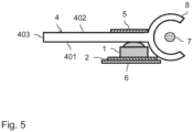
- FIG figure 5 shows a second variant of a lighting device according to the invention.
- the lighting device is shown in section and includes a variety of LED units 1, analogous to the lighting device 2 .
- the LED units are shown in the sectional view of the figure 5 arranged one behind the other perpendicular to the direction of the sheet.
- the individual LED units are in turn in direct contact with the underside 401 of the diffuser 4 .
- the light entering the diffuser via the LED units is as in the embodiment described above 2 directed to the light exit surface 403.
- a receptacle 8 is provided for a rod-shaped light guide 7, which is supplied with light via LEDs (not shown) at at least one coupling point.
- an optical reflector 5 is provided on the upper side 402 of the diffuser 4 .
- this reflector now extends only in an area above the individual LED units 1.
- a heat pipe 6 is in turn attached to the underside of the conductor track 2 for cooling the LED units 1. If necessary, the LED units can also be connected to one another discretely with lines.
- the corresponding light source (not shown) is coupled to a LIN bus in the motor vehicle at the coupling point 701 of the light rod 7 via a LIN module.
- a common processing module for all LED units 1 is preferably also located at this point, this processing module being connected via an electrical line to the conductor track 2 for data exchange with the LED units 1 and also being coupled to the LIN data bus.
- the coupling to the LIN data bus can take place at a single point, which ensures a simple construction of the lighting device.
- Control commands for controlling the LED units 1 and the light sources on the light rod 7 are transmitted from a control unit of the motor vehicle to the lighting device via the LIN bus.
- the data exchange between said processing module and the LED units takes place via an internal data bus in the form of an SPI bus, as has already been described above.
- a lighting device for a motor vehicle is created with a compact structure, since a corresponding diffuser can be placed directly in front of LED units or at a small distance.
- Light animations can also be generated in different configurations by appropriately controlling the LED units.
- a light rod can be provided in the lighting device as a further light source, with which light is also guided into the diffuser. In this way, further light effects can be achieved.
- a uniform light distribution for example in the color white, or a basic light animation can be generated by the light rod, where necessary, for example Depending on the operation or linked to certain events in the vehicle, a light animation can be switched on using different colors via appropriate control of the LED units.
Landscapes
- Engineering & Computer Science (AREA)
- General Engineering & Computer Science (AREA)
- Mechanical Engineering (AREA)
- Physics & Mathematics (AREA)
- Microelectronics & Electronic Packaging (AREA)
- Optics & Photonics (AREA)
- Arrangements Of Lighting Devices For Vehicle Interiors, Mounting And Supporting Thereof, Circuits Therefore (AREA)
- Non-Portable Lighting Devices Or Systems Thereof (AREA)
- Lighting Device Outwards From Vehicle And Optical Signal (AREA)
Claims (16)
- Dispositif d'éclairage pour un véhicule automobile, comprenantune ou plusieurs unités à LED (1), dans lequel chaque unité à LED (1) comprend une ou plusieurs LED ;un diffuseur en forme de plaque (4), constitué d'un matériau diffusant la lumière avec une première et une deuxième surface de délimitation (401, 402) ;dans lequelune face frontale du diffuseur (4), qui est disposée entre les première et deuxième surfaces de délimitation (401, 402), qui constitue la surface de sortie de lumière (403) du dispositif d'éclairage visible par un observateur ;l'unité à LED (1) ou les unités à LED (1) sont adjacentes à la première surface de délimitation (401) et émettent, lors du fonctionnement, en direction de la première surface de délimitation (401), une lumière qui entre dans le diffuseur (4) par l'intermédiaire de la première surface de délimitation (401) ;le diffuseur (4) est conçu et disposé de façon à ce qu'au moins une partie de la lumière de l'unité à LED (1) ou des unités à LED (1), qui entre par l'intermédiaire de la première surface de délimitation (401), soit guidée dans le diffuseur (4) jusqu'à la surface de sortie de lumière (403) et sorte du dispositif d'éclairage par l'intermédiaire de celle-ci.
- Dispositif d'éclairage selon la revendication 1, caractérisé en ce que l'unité à LED (1) ou les unités à LED (1) présentent une distance de 10 mm ou moins par rapport à la première surface de délimitation (401) et, plus particulièrement, s'appuient contre la première surface de délimitation (401).
- Dispositif d'éclairage selon l'une des revendications précédentes, caractérisé en ce que, pour l'unité à LED (1) ou les unités à LED (1), une direction de rayonnement principale (HS) est prédéfinie, selon laquelle l'unité à LED (1) respective émet symétriquement de la lumière, dans lequel la direction de rayonnement principale (HS) d'une unité à LED (1) respective est de préférence globalement perpendiculaire à la première surface de délimitation (401) à l'endroit de l'entrée de la lumière de l'unité à LED (1) respective dans la première surface de délimitation (401).
- Dispositif d'éclairage selon l'une des revendications précédentes, caractérisé en ce que le diffuseur (4) comprend une face frontale supplémentaire (404) qui est disposée sur une extrémité du diffuseur (4) éloignée de la surface de sortie de lumière (403), dans lequel l'unité à LED (1) ou les unités à LED (1) sont disposées de manière adjacente à la face frontale supplémentaire (404) .
- Dispositif d'éclairage selon l'une des revendications précédentes, caractérisé en ce que le diffuseur (4) représente une bande et la surface de sortie de lumière (403) est une arête longitudinale de la bande, dans lequel le dispositif d'éclairage comprend de préférence plusieurs unités à LED (1) qui sont disposées les unes à côté des autres dans la direction longitudinale de la bande.
- Dispositif d'éclairage selon la revendication 5, caractérisé en ce que la largeur de la bande représente entre 40 % et 250 %, plus particulièrement entre 50 % et 200 % de la distance entre des unités à LED (1) adjacentes.
- Dispositif d'éclairage selon l'une des revendications précédentes, caractérisé en ce que, sur la deuxième surface de délimitation (402) du diffuseur (4), est disposé, au moins dans la zone en face de l'unité ou des unités à LED (1), un réflecteur optique (5).
- Dispositif d'éclairage selon la revendication 7, caractérisé en ce que le réflecteur optique (5) est une partie d'un carénage du véhicule automobile.
- Dispositif d'éclairage selon l'une des revendications précédentes, caractérisé en ce que le dispositif d'éclairage est un éclairage intérieur dans le véhicule automobile ou un éclairage extérieur à l'extérieur du véhicule automobile.
- Dispositif d'éclairage selon l'une des revendications précédentes, caractérisé en ce que l'unité à LED (1) ou les unités à LED (1) sont disposées sur un dispositif de dissipation de chaleur (6).
- Dispositif d'éclairage selon l'une des revendications précédentes, caractérisé en ce que le dispositif d'éclairage comprend plusieurs unités à LED (1) qui sont disposées sur une bande conductrice commune (2) .
- Dispositif d'éclairage selon l'une des revendications précédentes, caractérisé en ce que le dispositif d'éclairage comprend en outre une fibre optique en forme de tige (7), dans lequel, à une ou aux deux extrémités (701, 702) de la fibre optique en forme de tige (7), sont disposées une ou plusieurs sources de lumière permettant d'introduire de la lumière dans la fibre optique en forme de tige (7), dans lequel la lumière introduite sort de la fibre optique en forme de tige (7) le long de la direction longitudinale de celle-ci et la fibre optique en forme de tige (7) est disposée sur le diffuseur (4) de façon à ce que la lumière qui en sort entre dans le diffuseur (4) et y soit guidé vers la surface de sortie de lumière (403).
- Dispositif d'éclairage selon la revendication 12, caractérisé en ce qu'au moins une source de lumière, qui introduit de la lumière à une extrémité de la fibre optique en forme de tige (7), peut être connectée, par l'intermédiaire d'un module d'interface, à un bus de données du véhicule automobile, dans lequel, à l'endroit du module d'interface, se trouve en outre un module de traitement qui est relié électriquement à l'unité ou les unités à LED (1) et qui peut également être connecté au bus de données du véhicule automobile.
- Dispositif d'éclairage selon l'une des revendications précédentes, caractérisé en ce que l'unité à LED (1) ou les unités à LED (1) comprennent chacune un circuit intégré pour le contrôle de la ou des LED de chaque unité à LED (1).
- Dispositif d'éclairage selon la revendication 14, caractérisé en ce que le dispositif d'éclairage comprend plusieurs unités à LED (1) qui sont couplées, par l'intermédiaire d'un bus de données interne, à un module de traitement commun, dans lequel le module de traitement est conçu pour être couplé à un bus de données du véhicule automobile, afin de recevoir des premières instructions de commande numériques pour le fonctionnement du dispositif d'éclairage, en provenance du bus de données du véhicule automobile et pour les envoyer, en tant que deuxièmes instructions de commande numériques, au bus interne, et dans lequel les unités à LED (1) sont conçues pour alimenter leurs LED en courant à l'aide d'une alimentation en tension sur la base des deuxièmes instructions de commande numériques sur le bus de données interne au moyen des circuits intégrés, dans lequel le bus de données interne est de préférence un bus SPI ou un bus de données différentiel.
- Véhicule automobile, comprenant un ou plusieurs dispositifs d'éclairage selon l'une des revendications précédentes.
Applications Claiming Priority (2)
| Application Number | Priority Date | Filing Date | Title |
|---|---|---|---|
| DE102015222505.4A DE102015222505A1 (de) | 2015-11-16 | 2015-11-16 | Beleuchtungsvorrichtung für ein Kraftfahrzeug |
| PCT/EP2016/075494 WO2017084836A1 (fr) | 2015-11-16 | 2016-10-24 | Dispositif d'éclairage pour un véhicule automobile |
Publications (2)
| Publication Number | Publication Date |
|---|---|
| EP3377370A1 EP3377370A1 (fr) | 2018-09-26 |
| EP3377370B1 true EP3377370B1 (fr) | 2023-07-05 |
Family
ID=57200003
Family Applications (1)
| Application Number | Title | Priority Date | Filing Date |
|---|---|---|---|
| EP16785467.8A Active EP3377370B1 (fr) | 2015-11-16 | 2016-10-24 | Dispositif d'éclairage pour un véhicule automobile |
Country Status (5)
| Country | Link |
|---|---|
| US (1) | US11447069B2 (fr) |
| EP (1) | EP3377370B1 (fr) |
| CN (1) | CN107921908B (fr) |
| DE (1) | DE102015222505A1 (fr) |
| WO (1) | WO2017084836A1 (fr) |
Families Citing this family (7)
| Publication number | Priority date | Publication date | Assignee | Title |
|---|---|---|---|---|
| EP3559549A4 (fr) * | 2016-12-22 | 2020-08-12 | Flex-N-gate Advanced Product Development, LLC | Lampe de véhicule à del homogène |
| DE102018202127A1 (de) | 2017-04-11 | 2018-10-11 | Volkswagen Aktiengesellschaft | Beleuchtungsvorrichtung zur Erzeugung eines Ambientelichts im Innenraum eines Kraftfahrzeugs |
| DE102017107969A1 (de) | 2017-04-12 | 2018-10-18 | Lisa Dräxlmaier GmbH | Beleuchtungsvorrichtung für ein Innenausstattungsteil eines Kraftfahrzeuges |
| DE102017211659A1 (de) * | 2017-07-07 | 2019-01-10 | Bayerische Motoren Werke Aktiengesellschaft | Beleuchtungseinheit für ein Fahrzeug und Verfahren zu dessen Herstellung |
| US10672327B1 (en) | 2019-01-02 | 2020-06-02 | Jvis-Usa, Llc | Low-profile display assembly for a vehicle and configured to display computer-generated imagery at the front of the assembly |
| US11766972B2 (en) | 2019-01-02 | 2023-09-26 | Jvis-Usa, Llc | Low-profile, backlit, panel assembly for displaying images and/or data within a passenger compartment of a vehicle |
| DE102019203502A1 (de) * | 2019-03-14 | 2020-09-17 | Volkswagen Aktiengesellschaft | Beleuchtungseinheit für ein Kraftfahrzeug |
Citations (3)
| Publication number | Priority date | Publication date | Assignee | Title |
|---|---|---|---|---|
| DE102010030660A1 (de) * | 2010-06-29 | 2011-12-29 | Lisa Dräxlmaier GmbH | Beleuchtetes Fahrzeuginnenausstattungsteil |
| WO2014179824A1 (fr) * | 2013-05-08 | 2014-11-13 | Zizala Lichtsysteme Gmbh | Dispositif d'éclairage pour véhicules à moteur |
| US20150198319A1 (en) * | 2013-11-21 | 2015-07-16 | Ford Glaobal Technologies, LLC | Photoluminescent dynamic lighting |
Family Cites Families (32)
| Publication number | Priority date | Publication date | Assignee | Title |
|---|---|---|---|---|
| US5197792A (en) * | 1992-04-21 | 1993-03-30 | General Motors Corporation | Illuminator device for a display panel |
| DE102004015544B4 (de) * | 2003-03-31 | 2009-05-07 | Toyoda Gosei Co., Ltd. | LED-Leuchte und Seitenspiegelvorrichtung |
| DE102005003132B8 (de) * | 2004-08-13 | 2010-07-22 | F.S. Fehrer Automotive Gmbh | Bauteil mit Hartschaumkörper und elektrischem und/oder elektronischem Funktionselement |
| DE202007016755U1 (de) * | 2006-05-11 | 2008-02-14 | Schefenacker Patents S.à.r.l. | Außenspiegel mit einer Leuchteneinheit |
| FR2916257B1 (fr) * | 2007-05-15 | 2012-12-14 | Valeo Vision | Dispositif de signalisation ou d'eclairage pour vehicule automobile |
| FR2928110B1 (fr) * | 2008-03-03 | 2010-06-11 | Valeo Vision | Systeme optique avec fonction principale pour vehicule automobile |
| US8258702B2 (en) * | 2008-05-21 | 2012-09-04 | Ford Global Technologies, Llc | Ambient LED lighting system and method |
| US8162519B2 (en) * | 2009-02-22 | 2012-04-24 | Ford Global Technologies, Llc | Concealed interior lighting for automobiles |
| FR2962704B1 (fr) * | 2010-07-16 | 2013-05-17 | Valeo Vision | Dispositif d'eclairage et/ou de signalisation d'un vehicule automobile |
| FR2967235B1 (fr) * | 2010-11-05 | 2014-10-31 | Valeo Vision | Dispositif d'eclairage ou de signalisation, pour vehicule automobile, comportant une nappe de guidage de lumiere. |
| DE102011016402A1 (de) * | 2011-04-08 | 2012-10-11 | GM Global Technology Operations LLC (n. d. Gesetzen des Staates Delaware) | Fahrzeugrückleuchte für ein Kraftfahrzeug |
| US8746939B2 (en) * | 2011-11-07 | 2014-06-10 | Ford Global Technologies, Llc | Crystal off-axis LED headlamp |
| DE102011089481A1 (de) * | 2011-12-21 | 2013-06-27 | Automotive Lighting Reutlingen Gmbh | Kraftfahrzeugbeleuchtungseinrichtung mit einer langen und flachen leuchtenden Fläche |
| DE102012005399A1 (de) * | 2012-03-16 | 2013-09-19 | Audi Ag | Beleuchtungseinrichtung, insbesondere Konturbeleuchtung für ein Kraftfahrzeug |
| DE102012107437B4 (de) * | 2012-08-14 | 2022-04-28 | HELLA GmbH & Co. KGaA | Leuchtvorrichtung |
| EP2902694B1 (fr) * | 2012-09-27 | 2020-11-04 | LG Innotek Co., Ltd. | Dispositif d'éclairage et lampe de véhicule le comprenant |
| DE102012109898A1 (de) * | 2012-10-17 | 2014-04-17 | Webasto SE | Verglasungskomponente, Beleuchtungssystem und Verfahren zur Herstellung einer Verglasungskomponente |
| FR2998678B1 (fr) * | 2012-11-29 | 2016-01-08 | Valeo Vision | Guide de lumiere pour un dispositif optique, notamment d'eclairage et/ou de signalisation |
| DE102012112152A1 (de) * | 2012-12-12 | 2014-06-12 | Dr. Ing. H.C. F. Porsche Aktiengesellschaft | Kraftfahrzeugrückleuchte |
| CN104995452B (zh) * | 2012-12-17 | 2018-07-20 | Lg伊诺特有限公司 | 用于车辆的照明单元 |
| WO2014123939A1 (fr) * | 2013-02-06 | 2014-08-14 | Innotec, Corp. | Plafonnier de pare-soleil de véhicule et système d'actionnement |
| DE102013202282A1 (de) * | 2013-02-13 | 2014-08-14 | Continental Automotive Gmbh | Lichtquelle und Verfahren zur Herstellung der Lichtquelle |
| ITPD20130075A1 (it) * | 2013-03-25 | 2014-09-26 | Automotive Lighting Italia Spa | Dispositivo di illuminazione e/o segnalazione per veicoli e relativo metodo di realizzazione |
| DE102013007938B4 (de) * | 2013-05-07 | 2019-05-23 | Motherson Innovations Lights GmbH & Co. KG | Flexibler Lichtleiter und Verfahren zur Herstellung eines flexiblen Lichtleiters |
| DE102014206238A1 (de) * | 2013-06-22 | 2014-12-24 | Volkswagen Aktiengesellschaft | Kraftfahrzeug mit einer Leuchtvorrichtung |
| JP5968276B2 (ja) * | 2013-07-30 | 2016-08-10 | 株式会社東海理化電機製作所 | 車両用ミラー装置 |
| ITTV20130134A1 (it) * | 2013-08-19 | 2015-02-20 | Automotive Lighting Italia Spa | Fanale automobilistico |
| JP5726973B2 (ja) * | 2013-09-27 | 2015-06-03 | 本田技研工業株式会社 | 灯火装置 |
| JP6249556B2 (ja) * | 2013-10-23 | 2017-12-20 | 株式会社小糸製作所 | 車輌用灯具 |
| CN104235726A (zh) * | 2014-08-28 | 2014-12-24 | 马瑞利汽车零部件(芜湖)有限公司 | 一种led汽车信号灯 |
| US9651211B2 (en) * | 2014-10-16 | 2017-05-16 | Valeo North America, Inc. | Multi-function optical system with shared exit optic |
| US10018325B2 (en) * | 2015-03-31 | 2018-07-10 | Seoul Semiconductor Co., Ltd. | Light device of vehicle |
-
2015
- 2015-11-16 DE DE102015222505.4A patent/DE102015222505A1/de active Pending
-
2016
- 2016-10-24 EP EP16785467.8A patent/EP3377370B1/fr active Active
- 2016-10-24 CN CN201680046951.XA patent/CN107921908B/zh active Active
- 2016-10-24 WO PCT/EP2016/075494 patent/WO2017084836A1/fr active Application Filing
-
2018
- 2018-05-15 US US15/980,443 patent/US11447069B2/en active Active
Patent Citations (3)
| Publication number | Priority date | Publication date | Assignee | Title |
|---|---|---|---|---|
| DE102010030660A1 (de) * | 2010-06-29 | 2011-12-29 | Lisa Dräxlmaier GmbH | Beleuchtetes Fahrzeuginnenausstattungsteil |
| WO2014179824A1 (fr) * | 2013-05-08 | 2014-11-13 | Zizala Lichtsysteme Gmbh | Dispositif d'éclairage pour véhicules à moteur |
| US20150198319A1 (en) * | 2013-11-21 | 2015-07-16 | Ford Glaobal Technologies, LLC | Photoluminescent dynamic lighting |
Also Published As
| Publication number | Publication date |
|---|---|
| WO2017084836A1 (fr) | 2017-05-26 |
| EP3377370A1 (fr) | 2018-09-26 |
| CN107921908B (zh) | 2021-11-09 |
| US11447069B2 (en) | 2022-09-20 |
| US20180257557A1 (en) | 2018-09-13 |
| CN107921908A (zh) | 2018-04-17 |
| DE102015222505A1 (de) | 2017-05-18 |
Similar Documents
| Publication | Publication Date | Title |
|---|---|---|
| EP3377370B1 (fr) | Dispositif d'éclairage pour un véhicule automobile | |
| DE102018119334B4 (de) | Beleuchtungsvorrichtung und/oder signalisierungsvorrichtung für ein kraftfahrzeug | |
| EP3538812B1 (fr) | Dispositif d'éclairage, notamment pour véhicule automobile | |
| EP2444283B1 (fr) | Module d'éclairage | |
| DE102007043903A1 (de) | Leucht-Vorrichtung | |
| DE102016121047A1 (de) | Beleuchtungseinrichtung für ein fahrzeug sowie herstellungsverfahren für eine beleuchtungseinrichtung | |
| EP3825601A1 (fr) | Élément lumineux pour un véhicule automobile et véhicule automobile | |
| EP2986902B1 (fr) | Éclairage intérieur pour véhicule automobile | |
| DE102010054929A1 (de) | Leuchteinrichtung für ein Fahrzeug mit einem lichtleitenden Optikelement | |
| EP4041599B1 (fr) | Dispositif de signalisation lumineuse pour un système de transport sans conducteur | |
| WO2015154939A1 (fr) | Dispositif d'affichage d'un symbole et procédé de production d'un dispositif d'affichage d'un symbole | |
| DE102016200393B4 (de) | Beleuchtungseinrichtung für Fahrzeuge, insbesondere zur Integration in Fahrzeugtüren | |
| DE102013101198B4 (de) | Beleuchtungsvorrichtung für Fahrzeuge sowie Verfahren | |
| DE102015007610B4 (de) | Beleuchtungseinrichtung zur segmentierten Beleuchtung, insbesondere zur Ambiente-Beleuchtung im Innenraum eines Fahrzeuges | |
| EP1767402B1 (fr) | Dispositif d'affichage | |
| EP3853518A1 (fr) | Module d'éclairage, notamment destiné à être utilisé dans un dispositif d'éclairage pour véhicule automobile | |
| WO2022238111A1 (fr) | Dispositif d'éclairage pour l'intérieur d'un véhicule automobile | |
| DE202021003965U1 (de) | Beleuchtungsvorrichtung | |
| EP3954581A1 (fr) | Dispositif d'éclairage pour véhicules | |
| DE102020128555A1 (de) | Beleuchtungsvorrichtung für ein Kraftfahrzeug | |
| WO2022218602A1 (fr) | Dispositif lumineux de communication pour habitacle de véhicule et véhicule automobile équipé d'un dispositif lumineux de communication | |
| EP3954582A1 (fr) | Dispositif d'éclairage pour véhicules | |
| EP3814172B1 (fr) | Procédé de fabrication d'un module de clignotant ainsi que module de clignotant, système de rétroviseur et véhicule automobile | |
| DE102014010310B3 (de) | Beleuchtetes Zeigerinstrument für ein Kraftfahrzeug | |
| DE102020204906A1 (de) | Heckklappe eines Fahrzeugs mit einer Beleuchtungsanordnung an einteiligem Außenblech |
Legal Events
| Date | Code | Title | Description |
|---|---|---|---|
| STAA | Information on the status of an ep patent application or granted ep patent |
Free format text: STATUS: UNKNOWN |
|
| STAA | Information on the status of an ep patent application or granted ep patent |
Free format text: STATUS: THE INTERNATIONAL PUBLICATION HAS BEEN MADE |
|
| PUAI | Public reference made under article 153(3) epc to a published international application that has entered the european phase |
Free format text: ORIGINAL CODE: 0009012 |
|
| STAA | Information on the status of an ep patent application or granted ep patent |
Free format text: STATUS: REQUEST FOR EXAMINATION WAS MADE |
|
| 17P | Request for examination filed |
Effective date: 20180611 |
|
| AK | Designated contracting states |
Kind code of ref document: A1 Designated state(s): AL AT BE BG CH CY CZ DE DK EE ES FI FR GB GR HR HU IE IS IT LI LT LU LV MC MK MT NL NO PL PT RO RS SE SI SK SM TR |
|
| AX | Request for extension of the european patent |
Extension state: BA ME |
|
| DAV | Request for validation of the european patent (deleted) | ||
| DAX | Request for extension of the european patent (deleted) | ||
| STAA | Information on the status of an ep patent application or granted ep patent |
Free format text: STATUS: EXAMINATION IS IN PROGRESS |
|
| STAA | Information on the status of an ep patent application or granted ep patent |
Free format text: STATUS: EXAMINATION IS IN PROGRESS |
|
| 17Q | First examination report despatched |
Effective date: 20211117 |
|
| REG | Reference to a national code |
Ref country code: DE Ref legal event code: R079 Ref document number: 502016015927 Country of ref document: DE Free format text: PREVIOUS MAIN CLASS: B60Q0003000000 Ipc: B60Q0003640000 Ref country code: DE Ref legal event code: R079 Free format text: PREVIOUS MAIN CLASS: B60Q0003000000 Ipc: B60Q0003640000 |
|
| GRAP | Despatch of communication of intention to grant a patent |
Free format text: ORIGINAL CODE: EPIDOSNIGR1 |
|
| STAA | Information on the status of an ep patent application or granted ep patent |
Free format text: STATUS: GRANT OF PATENT IS INTENDED |
|
| RIC1 | Information provided on ipc code assigned before grant |
Ipc: B60Q 3/54 20170101ALI20230220BHEP Ipc: F21S 43/20 20180101ALI20230220BHEP Ipc: F21S 43/249 20180101ALI20230220BHEP Ipc: F21S 43/243 20180101ALI20230220BHEP Ipc: F21S 43/239 20180101ALI20230220BHEP Ipc: F21S 43/237 20180101ALI20230220BHEP Ipc: F21S 43/14 20180101ALI20230220BHEP Ipc: B60Q 3/74 20170101ALI20230220BHEP Ipc: B60Q 3/64 20170101AFI20230220BHEP |
|
| INTG | Intention to grant announced |
Effective date: 20230329 |
|
| GRAS | Grant fee paid |
Free format text: ORIGINAL CODE: EPIDOSNIGR3 |
|
| GRAA | (expected) grant |
Free format text: ORIGINAL CODE: 0009210 |
|
| STAA | Information on the status of an ep patent application or granted ep patent |
Free format text: STATUS: THE PATENT HAS BEEN GRANTED |
|
| P01 | Opt-out of the competence of the unified patent court (upc) registered |
Effective date: 20230503 |
|
| AK | Designated contracting states |
Kind code of ref document: B1 Designated state(s): AL AT BE BG CH CY CZ DE DK EE ES FI FR GB GR HR HU IE IS IT LI LT LU LV MC MK MT NL NO PL PT RO RS SE SI SK SM TR |
|
| REG | Reference to a national code |
Ref country code: CH Ref legal event code: EP |
|
| REG | Reference to a national code |
Ref country code: AT Ref legal event code: REF Ref document number: 1584573 Country of ref document: AT Kind code of ref document: T Effective date: 20230715 |
|
| REG | Reference to a national code |
Ref country code: DE Ref legal event code: R096 Ref document number: 502016015927 Country of ref document: DE |
|
| REG | Reference to a national code |
Ref country code: IE Ref legal event code: FG4D Free format text: LANGUAGE OF EP DOCUMENT: GERMAN |
|
| P02 | Opt-out of the competence of the unified patent court (upc) changed |
Effective date: 20230801 |
|
| REG | Reference to a national code |
Ref country code: LT Ref legal event code: MG9D |
|
| REG | Reference to a national code |
Ref country code: NL Ref legal event code: MP Effective date: 20230705 |
|
| PG25 | Lapsed in a contracting state [announced via postgrant information from national office to epo] |
Ref country code: NL Free format text: LAPSE BECAUSE OF FAILURE TO SUBMIT A TRANSLATION OF THE DESCRIPTION OR TO PAY THE FEE WITHIN THE PRESCRIBED TIME-LIMIT Effective date: 20230705 |
|
| PG25 | Lapsed in a contracting state [announced via postgrant information from national office to epo] |
Ref country code: GR Free format text: LAPSE BECAUSE OF FAILURE TO SUBMIT A TRANSLATION OF THE DESCRIPTION OR TO PAY THE FEE WITHIN THE PRESCRIBED TIME-LIMIT Effective date: 20231006 |
|
| PGFP | Annual fee paid to national office [announced via postgrant information from national office to epo] |
Ref country code: GB Payment date: 20231025 Year of fee payment: 8 |
|
| PG25 | Lapsed in a contracting state [announced via postgrant information from national office to epo] |
Ref country code: ES Free format text: LAPSE BECAUSE OF FAILURE TO SUBMIT A TRANSLATION OF THE DESCRIPTION OR TO PAY THE FEE WITHIN THE PRESCRIBED TIME-LIMIT Effective date: 20230705 |
|
| PG25 | Lapsed in a contracting state [announced via postgrant information from national office to epo] |
Ref country code: IS Free format text: LAPSE BECAUSE OF FAILURE TO SUBMIT A TRANSLATION OF THE DESCRIPTION OR TO PAY THE FEE WITHIN THE PRESCRIBED TIME-LIMIT Effective date: 20231105 |
|
| PG25 | Lapsed in a contracting state [announced via postgrant information from national office to epo] |
Ref country code: SE Free format text: LAPSE BECAUSE OF FAILURE TO SUBMIT A TRANSLATION OF THE DESCRIPTION OR TO PAY THE FEE WITHIN THE PRESCRIBED TIME-LIMIT Effective date: 20230705 Ref country code: RS Free format text: LAPSE BECAUSE OF FAILURE TO SUBMIT A TRANSLATION OF THE DESCRIPTION OR TO PAY THE FEE WITHIN THE PRESCRIBED TIME-LIMIT Effective date: 20230705 Ref country code: PT Free format text: LAPSE BECAUSE OF FAILURE TO SUBMIT A TRANSLATION OF THE DESCRIPTION OR TO PAY THE FEE WITHIN THE PRESCRIBED TIME-LIMIT Effective date: 20231106 Ref country code: NO Free format text: LAPSE BECAUSE OF FAILURE TO SUBMIT A TRANSLATION OF THE DESCRIPTION OR TO PAY THE FEE WITHIN THE PRESCRIBED TIME-LIMIT Effective date: 20231005 Ref country code: LV Free format text: LAPSE BECAUSE OF FAILURE TO SUBMIT A TRANSLATION OF THE DESCRIPTION OR TO PAY THE FEE WITHIN THE PRESCRIBED TIME-LIMIT Effective date: 20230705 Ref country code: LT Free format text: LAPSE BECAUSE OF FAILURE TO SUBMIT A TRANSLATION OF THE DESCRIPTION OR TO PAY THE FEE WITHIN THE PRESCRIBED TIME-LIMIT Effective date: 20230705 Ref country code: IS Free format text: LAPSE BECAUSE OF FAILURE TO SUBMIT A TRANSLATION OF THE DESCRIPTION OR TO PAY THE FEE WITHIN THE PRESCRIBED TIME-LIMIT Effective date: 20231105 Ref country code: HR Free format text: LAPSE BECAUSE OF FAILURE TO SUBMIT A TRANSLATION OF THE DESCRIPTION OR TO PAY THE FEE WITHIN THE PRESCRIBED TIME-LIMIT Effective date: 20230705 Ref country code: GR Free format text: LAPSE BECAUSE OF FAILURE TO SUBMIT A TRANSLATION OF THE DESCRIPTION OR TO PAY THE FEE WITHIN THE PRESCRIBED TIME-LIMIT Effective date: 20231006 Ref country code: FI Free format text: LAPSE BECAUSE OF FAILURE TO SUBMIT A TRANSLATION OF THE DESCRIPTION OR TO PAY THE FEE WITHIN THE PRESCRIBED TIME-LIMIT Effective date: 20230705 Ref country code: ES Free format text: LAPSE BECAUSE OF FAILURE TO SUBMIT A TRANSLATION OF THE DESCRIPTION OR TO PAY THE FEE WITHIN THE PRESCRIBED TIME-LIMIT Effective date: 20230705 |
|
| PGFP | Annual fee paid to national office [announced via postgrant information from national office to epo] |
Ref country code: FR Payment date: 20231023 Year of fee payment: 8 Ref country code: DE Payment date: 20231017 Year of fee payment: 8 |
|
| PG25 | Lapsed in a contracting state [announced via postgrant information from national office to epo] |
Ref country code: PL Free format text: LAPSE BECAUSE OF FAILURE TO SUBMIT A TRANSLATION OF THE DESCRIPTION OR TO PAY THE FEE WITHIN THE PRESCRIBED TIME-LIMIT Effective date: 20230705 |
|
| REG | Reference to a national code |
Ref country code: DE Ref legal event code: R097 Ref document number: 502016015927 Country of ref document: DE |
|
| PG25 | Lapsed in a contracting state [announced via postgrant information from national office to epo] |
Ref country code: SM Free format text: LAPSE BECAUSE OF FAILURE TO SUBMIT A TRANSLATION OF THE DESCRIPTION OR TO PAY THE FEE WITHIN THE PRESCRIBED TIME-LIMIT Effective date: 20230705 Ref country code: RO Free format text: LAPSE BECAUSE OF FAILURE TO SUBMIT A TRANSLATION OF THE DESCRIPTION OR TO PAY THE FEE WITHIN THE PRESCRIBED TIME-LIMIT Effective date: 20230705 Ref country code: EE Free format text: LAPSE BECAUSE OF FAILURE TO SUBMIT A TRANSLATION OF THE DESCRIPTION OR TO PAY THE FEE WITHIN THE PRESCRIBED TIME-LIMIT Effective date: 20230705 Ref country code: DK Free format text: LAPSE BECAUSE OF FAILURE TO SUBMIT A TRANSLATION OF THE DESCRIPTION OR TO PAY THE FEE WITHIN THE PRESCRIBED TIME-LIMIT Effective date: 20230705 Ref country code: CZ Free format text: LAPSE BECAUSE OF FAILURE TO SUBMIT A TRANSLATION OF THE DESCRIPTION OR TO PAY THE FEE WITHIN THE PRESCRIBED TIME-LIMIT Effective date: 20230705 Ref country code: SK Free format text: LAPSE BECAUSE OF FAILURE TO SUBMIT A TRANSLATION OF THE DESCRIPTION OR TO PAY THE FEE WITHIN THE PRESCRIBED TIME-LIMIT Effective date: 20230705 |
|
| PLBE | No opposition filed within time limit |
Free format text: ORIGINAL CODE: 0009261 |
|
| STAA | Information on the status of an ep patent application or granted ep patent |
Free format text: STATUS: NO OPPOSITION FILED WITHIN TIME LIMIT |
|
| PG25 | Lapsed in a contracting state [announced via postgrant information from national office to epo] |
Ref country code: IT Free format text: LAPSE BECAUSE OF FAILURE TO SUBMIT A TRANSLATION OF THE DESCRIPTION OR TO PAY THE FEE WITHIN THE PRESCRIBED TIME-LIMIT Effective date: 20230705 Ref country code: MC Free format text: LAPSE BECAUSE OF FAILURE TO SUBMIT A TRANSLATION OF THE DESCRIPTION OR TO PAY THE FEE WITHIN THE PRESCRIBED TIME-LIMIT Effective date: 20230705 |
|
| REG | Reference to a national code |
Ref country code: CH Ref legal event code: PL |
|
| 26N | No opposition filed |
Effective date: 20240408 |
|
| REG | Reference to a national code |
Ref country code: BE Ref legal event code: MM Effective date: 20231031 |
|
| PG25 | Lapsed in a contracting state [announced via postgrant information from national office to epo] |
Ref country code: LU Free format text: LAPSE BECAUSE OF NON-PAYMENT OF DUE FEES Effective date: 20231024 |
|
| PG25 | Lapsed in a contracting state [announced via postgrant information from national office to epo] |
Ref country code: LU Free format text: LAPSE BECAUSE OF NON-PAYMENT OF DUE FEES Effective date: 20231024 |
|
| PG25 | Lapsed in a contracting state [announced via postgrant information from national office to epo] |
Ref country code: CH Free format text: LAPSE BECAUSE OF NON-PAYMENT OF DUE FEES Effective date: 20231031 |
|
| PG25 | Lapsed in a contracting state [announced via postgrant information from national office to epo] |
Ref country code: CH Free format text: LAPSE BECAUSE OF NON-PAYMENT OF DUE FEES Effective date: 20231031 Ref country code: SI Free format text: LAPSE BECAUSE OF FAILURE TO SUBMIT A TRANSLATION OF THE DESCRIPTION OR TO PAY THE FEE WITHIN THE PRESCRIBED TIME-LIMIT Effective date: 20230705 |
|
| PG25 | Lapsed in a contracting state [announced via postgrant information from national office to epo] |
Ref country code: BE Free format text: LAPSE BECAUSE OF NON-PAYMENT OF DUE FEES Effective date: 20231031 |