EP3377370B1 - Illumination device for a motor vehicle - Google Patents
Illumination device for a motor vehicle Download PDFInfo
- Publication number
- EP3377370B1 EP3377370B1 EP16785467.8A EP16785467A EP3377370B1 EP 3377370 B1 EP3377370 B1 EP 3377370B1 EP 16785467 A EP16785467 A EP 16785467A EP 3377370 B1 EP3377370 B1 EP 3377370B1
- Authority
- EP
- European Patent Office
- Prior art keywords
- light
- lighting apparatus
- diffuser
- led
- led units
- Prior art date
- Legal status (The legal status is an assumption and is not a legal conclusion. Google has not performed a legal analysis and makes no representation as to the accuracy of the status listed.)
- Active
Links
- 238000005286 illumination Methods 0.000 title 1
- 238000012545 processing Methods 0.000 claims description 14
- 230000003287 optical effect Effects 0.000 claims description 13
- 239000004020 conductor Substances 0.000 claims description 10
- 239000000463 material Substances 0.000 claims description 10
- 238000000149 argon plasma sintering Methods 0.000 claims description 6
- 238000009826 distribution Methods 0.000 description 8
- 230000008878 coupling Effects 0.000 description 7
- 238000010168 coupling process Methods 0.000 description 7
- 238000005859 coupling reaction Methods 0.000 description 7
- 238000011161 development Methods 0.000 description 4
- 230000018109 developmental process Effects 0.000 description 4
- 230000017525 heat dissipation Effects 0.000 description 4
- 238000009434 installation Methods 0.000 description 4
- 238000012856 packing Methods 0.000 description 3
- 239000003086 colorant Substances 0.000 description 2
- 238000001816 cooling Methods 0.000 description 2
- 239000011888 foil Substances 0.000 description 2
- 230000001795 light effect Effects 0.000 description 2
- 239000004033 plastic Substances 0.000 description 2
- 229920003023 plastic Polymers 0.000 description 2
- 239000004952 Polyamide Substances 0.000 description 1
- 238000010276 construction Methods 0.000 description 1
- 230000001419 dependent effect Effects 0.000 description 1
- 238000013461 design Methods 0.000 description 1
- 239000005338 frosted glass Substances 0.000 description 1
- 230000003760 hair shine Effects 0.000 description 1
- 238000000034 method Methods 0.000 description 1
- 239000011022 opal Substances 0.000 description 1
- 239000013307 optical fiber Substances 0.000 description 1
- 229920003229 poly(methyl methacrylate) Polymers 0.000 description 1
- 229920002647 polyamide Polymers 0.000 description 1
- 239000004417 polycarbonate Substances 0.000 description 1
- 229920000515 polycarbonate Polymers 0.000 description 1
- 239000004926 polymethyl methacrylate Substances 0.000 description 1
- 230000003595 spectral effect Effects 0.000 description 1
Images


Classifications
-
- B—PERFORMING OPERATIONS; TRANSPORTING
- B60—VEHICLES IN GENERAL
- B60Q—ARRANGEMENT OF SIGNALLING OR LIGHTING DEVICES, THE MOUNTING OR SUPPORTING THEREOF OR CIRCUITS THEREFOR, FOR VEHICLES IN GENERAL
- B60Q3/00—Arrangement of lighting devices for vehicle interiors; Lighting devices specially adapted for vehicle interiors
- B60Q3/60—Arrangement of lighting devices for vehicle interiors; Lighting devices specially adapted for vehicle interiors characterised by optical aspects
- B60Q3/62—Arrangement of lighting devices for vehicle interiors; Lighting devices specially adapted for vehicle interiors characterised by optical aspects using light guides
- B60Q3/64—Arrangement of lighting devices for vehicle interiors; Lighting devices specially adapted for vehicle interiors characterised by optical aspects using light guides for a single lighting device
-
- B—PERFORMING OPERATIONS; TRANSPORTING
- B60—VEHICLES IN GENERAL
- B60Q—ARRANGEMENT OF SIGNALLING OR LIGHTING DEVICES, THE MOUNTING OR SUPPORTING THEREOF OR CIRCUITS THEREFOR, FOR VEHICLES IN GENERAL
- B60Q3/00—Arrangement of lighting devices for vehicle interiors; Lighting devices specially adapted for vehicle interiors
- B60Q3/50—Mounting arrangements
- B60Q3/54—Lighting devices embedded in interior trim, e.g. in roof liners
-
- B—PERFORMING OPERATIONS; TRANSPORTING
- B60—VEHICLES IN GENERAL
- B60Q—ARRANGEMENT OF SIGNALLING OR LIGHTING DEVICES, THE MOUNTING OR SUPPORTING THEREOF OR CIRCUITS THEREFOR, FOR VEHICLES IN GENERAL
- B60Q3/00—Arrangement of lighting devices for vehicle interiors; Lighting devices specially adapted for vehicle interiors
- B60Q3/70—Arrangement of lighting devices for vehicle interiors; Lighting devices specially adapted for vehicle interiors characterised by the purpose
- B60Q3/74—Arrangement of lighting devices for vehicle interiors; Lighting devices specially adapted for vehicle interiors characterised by the purpose for overall compartment lighting; for overall compartment lighting in combination with specific lighting, e.g. room lamps with reading lamps
- B60Q3/745—Arrangement of lighting devices for vehicle interiors; Lighting devices specially adapted for vehicle interiors characterised by the purpose for overall compartment lighting; for overall compartment lighting in combination with specific lighting, e.g. room lamps with reading lamps using lighting panels or mats, e.g. electro-luminescent panels, LED mats
-
- F—MECHANICAL ENGINEERING; LIGHTING; HEATING; WEAPONS; BLASTING
- F21—LIGHTING
- F21S—NON-PORTABLE LIGHTING DEVICES; SYSTEMS THEREOF; VEHICLE LIGHTING DEVICES SPECIALLY ADAPTED FOR VEHICLE EXTERIORS
- F21S43/00—Signalling devices specially adapted for vehicle exteriors, e.g. brake lamps, direction indicator lights or reversing lights
- F21S43/10—Signalling devices specially adapted for vehicle exteriors, e.g. brake lamps, direction indicator lights or reversing lights characterised by the light source
- F21S43/13—Signalling devices specially adapted for vehicle exteriors, e.g. brake lamps, direction indicator lights or reversing lights characterised by the light source characterised by the type of light source
- F21S43/14—Light emitting diodes [LED]
-
- F—MECHANICAL ENGINEERING; LIGHTING; HEATING; WEAPONS; BLASTING
- F21—LIGHTING
- F21S—NON-PORTABLE LIGHTING DEVICES; SYSTEMS THEREOF; VEHICLE LIGHTING DEVICES SPECIALLY ADAPTED FOR VEHICLE EXTERIORS
- F21S43/00—Signalling devices specially adapted for vehicle exteriors, e.g. brake lamps, direction indicator lights or reversing lights
- F21S43/20—Signalling devices specially adapted for vehicle exteriors, e.g. brake lamps, direction indicator lights or reversing lights characterised by refractors, transparent cover plates, light guides or filters
- F21S43/235—Light guides
- F21S43/236—Light guides characterised by the shape of the light guide
- F21S43/237—Light guides characterised by the shape of the light guide rod-shaped
-
- F—MECHANICAL ENGINEERING; LIGHTING; HEATING; WEAPONS; BLASTING
- F21—LIGHTING
- F21S—NON-PORTABLE LIGHTING DEVICES; SYSTEMS THEREOF; VEHICLE LIGHTING DEVICES SPECIALLY ADAPTED FOR VEHICLE EXTERIORS
- F21S43/00—Signalling devices specially adapted for vehicle exteriors, e.g. brake lamps, direction indicator lights or reversing lights
- F21S43/20—Signalling devices specially adapted for vehicle exteriors, e.g. brake lamps, direction indicator lights or reversing lights characterised by refractors, transparent cover plates, light guides or filters
- F21S43/235—Light guides
- F21S43/236—Light guides characterised by the shape of the light guide
- F21S43/239—Light guides characterised by the shape of the light guide plate-shaped
-
- F—MECHANICAL ENGINEERING; LIGHTING; HEATING; WEAPONS; BLASTING
- F21—LIGHTING
- F21S—NON-PORTABLE LIGHTING DEVICES; SYSTEMS THEREOF; VEHICLE LIGHTING DEVICES SPECIALLY ADAPTED FOR VEHICLE EXTERIORS
- F21S43/00—Signalling devices specially adapted for vehicle exteriors, e.g. brake lamps, direction indicator lights or reversing lights
- F21S43/20—Signalling devices specially adapted for vehicle exteriors, e.g. brake lamps, direction indicator lights or reversing lights characterised by refractors, transparent cover plates, light guides or filters
- F21S43/235—Light guides
- F21S43/242—Light guides characterised by the emission area
- F21S43/243—Light guides characterised by the emission area emitting light from one or more of its extremities
-
- F—MECHANICAL ENGINEERING; LIGHTING; HEATING; WEAPONS; BLASTING
- F21—LIGHTING
- F21S—NON-PORTABLE LIGHTING DEVICES; SYSTEMS THEREOF; VEHICLE LIGHTING DEVICES SPECIALLY ADAPTED FOR VEHICLE EXTERIORS
- F21S43/00—Signalling devices specially adapted for vehicle exteriors, e.g. brake lamps, direction indicator lights or reversing lights
- F21S43/20—Signalling devices specially adapted for vehicle exteriors, e.g. brake lamps, direction indicator lights or reversing lights characterised by refractors, transparent cover plates, light guides or filters
- F21S43/235—Light guides
- F21S43/249—Light guides with two or more light sources being coupled into the light guide
-
- F—MECHANICAL ENGINEERING; LIGHTING; HEATING; WEAPONS; BLASTING
- F21—LIGHTING
- F21S—NON-PORTABLE LIGHTING DEVICES; SYSTEMS THEREOF; VEHICLE LIGHTING DEVICES SPECIALLY ADAPTED FOR VEHICLE EXTERIORS
- F21S43/00—Signalling devices specially adapted for vehicle exteriors, e.g. brake lamps, direction indicator lights or reversing lights
- F21S43/20—Signalling devices specially adapted for vehicle exteriors, e.g. brake lamps, direction indicator lights or reversing lights characterised by refractors, transparent cover plates, light guides or filters
- F21S43/26—Refractors, transparent cover plates, light guides or filters not provided in groups F21S43/235 - F21S43/255
Definitions
- the invention relates to a lighting device for a motor vehicle.
- Lighting devices for motor vehicles are known from the prior art, which can generate different types of light distributions in the interior as well as outside of the vehicle by means of LED units.
- plate-shaped diffusers made of light-scattering material are often used in such lighting devices, with the light from the LED units passing through the diffuser in the direction of its thickness.
- a sufficient distance between the diffuser and the LED units must be maintained, otherwise the individual light points of the LED units will become visible, which means that the appearance of the generated light distribution will be inhomogeneous. Due to the distance to be provided between diffuser and LED units, which should be at least 50% of the distance between adjacent LED units, a lot of installation space is required for the lighting device, so that it can be used for many applications in motor vehicles, such as ambient or lighting Contour lighting, which cannot be used or is very difficult to use due to the lack of space.
- the pamphlet EP 2 407 709 A2 discloses a lighting device for a motor vehicle with light guides. The light from an LED is radiated in via a boundary surface of a respective light guide and emerges again via an end face of the respective light guide.
- the pamphlets DE 10 2012 109 898 A1 and DE 10 2011 016 402 A1 disclose lighting devices for motor vehicles that use light-diffusing materials.
- the pamphlet EP 2 816 276 A2 discloses a motor vehicle with a lighting device that includes a light guide with a coupling-in surface and a coupling-out surface.
- the decoupling surface is provided on an end face of the light guide and contains light-scattering plastic.
- the object of the invention is to create a lighting device for a motor vehicle with small dimensions.
- the lighting device is provided for a motor vehicle, such as a passenger car or possibly also a truck or a motorcycle. It comprises one or more LED units, with each LED unit comprising one or more LEDs.
- the LED units can be RGB LED units with a red, green, and blue LED and/or RGBW LED units with a red, green, blue, and white LED, and optionally also white light LED units with a single LED white LED or single color LED units with a single colored LED.
- LED units are of the type APA10x or WS281x and their further technical developments are used. However, other LEDs can also be used if necessary.
- a plate-shaped diffuser with a first and a second boundary surface is also provided in the lighting device according to the invention.
- a light-scattering material with a predetermined thickness is located between these boundary surfaces.
- the first and second delimiting surfaces are therefore in the two-dimensional extent of the diffuser.
- the concept of the plate-shaped diffuser is to be understood broadly, i.e. the diffuser does not necessarily have to comprise a flat plate, but it can also be designed as any curved or corrugated plate.
- the predetermined thickness is in the range between 1 mm and 5 mm.
- the lighting device has a plate-shaped diffuser made of light-scattering material with a first and second boundary surface and an end face of the diffuser.
- the front surface of the diffuser which is provided between the first and second boundary surfaces, forms the light exit surface visible to an observer and in particular the only visible light exit surface of the lighting device.
- the LED unit or the LED units are/are arranged adjacent to the first boundary surface and, during operation, emit light in the direction of the first boundary surface. This light enters the diffuser via the first boundary surface.
- the light from the LED unit or LED units preferably shines directly onto the first boundary surface, i.e. the light does not pass through any optical components between the LED unit or LED units and the first boundary surface.
- the LED unit or LED units are at a distance of 10 mm or less from the first boundary surface.
- the LED unit or the LED units are preferably in contact with the first boundary surface.
- the diffuser of the lighting device according to the invention is designed and arranged in such a way that at least part of the light entering via the first boundary surface of the LED unit or LED units is guided in the diffuser to the light exit surface and exits the lighting device there.
- the light is guided in the diffuser via reflections on the first and second boundary surfaces.
- the lighting device according to the invention has the advantage that a very compact design of the lighting device is achieved by light exiting at an end face of the diffuser and thus in a different direction than the light entry.
- the lighting device can thus also be installed in areas of the motor vehicle where space is limited, such as in door panels, instrument panels, center consoles and the like. Furthermore, the generation of a homogeneous light distribution is achieved by the light distribution in the diffuser.
- a main beam direction is specified for the LED unit or LED units, based on which the respective LED unit emits light symmetrically.
- the main beam direction of a respective LED unit is preferably essentially perpendicular to the first delimiting surface at the point at which the light of the respective LED unit enters the first delimiting surface.
- the plate-shaped diffuser comprises a further end face which is arranged at an end of the diffuser remote from the light exit surface, the LED unit or LED units being arranged adjacent to the further end face. This ensures that the light travels a long way in the diffuser, so that the light distribution generated on the light exit surface is particularly homogeneous.
- the diffuser represents a strip and the light exit surface is a longitudinal edge of the strip, the lighting device preferably comprising a plurality of LED units which are arranged next to one another in the direction of the longitudinal direction of the strip.
- the LED units can be positioned along the strip with different packing densities and thus different distances from one another.
- packing densities of, for example, 144-367 LED units per meter can be achieved, which corresponds to a distance between the LED units of around 7 mm and less.
- the packing densities can also be lower and can be, for example, 72 or 60 or 30 LED units per meter.
- the width of the diffuser designed as a strip is between 40% and 250%, in particular between 50% and 200%, of the (constant) distance between adjacent LEDs. The greater the width of the strip, the more homogeneous the light distribution generated.
- an optical reflector is arranged on the second boundary surface of the diffuser, at least in the area which is opposite the LED unit or units. In this way, the light losses in the diffuser are kept low.
- the optical reflector can optionally be part of a paneling of the motor vehicle. Furthermore, the reflector can optionally also cover the entire second boundary surface.
- the lighting device according to the invention can be an interior light in the motor vehicle or also an external light on the outside of the motor vehicle. Accordingly, the reflector just described can be part of an interior paneling of the motor vehicle, for example.
- the LED unit or LED units are arranged on a heat sink, e.g. This ensures efficient dissipation of the heat generated by the LED units, even with a small installation space.
- the lighting device according to the invention comprises a number of LED units which are arranged on a common printed circuit board or conductor track. If a heat dissipation is provided, this can be formed, for example, on one side of the common conductor track.
- the lighting device according to the invention also comprises a rod-shaped light guide, for example a cylindrical light guide.
- one or more light sources for example LEDs
- the rod-shaped light guide for feeding light into the rod-shaped light guide.
- the light fed in emerges from the rod-shaped light guide along the longitudinal direction thereof and the rod-shaped light guide is arranged on the diffuser in such a way that the light emerging from it Light enters the diffuser and is directed there to the light exit surface.
- This variant of the invention enables additional generation of light by means of a rod-shaped light guide. Many different light effects can be produced with such a lighting device.
- white light can be generated via the rod-shaped light guide, which is then overlaid with suitable colored animations that are generated with the LED units adjacent to the first boundary surface.
- At least one light source which feeds light at one end of the rod-shaped light guide, is connected to a motor vehicle data bus via an interface module, with a processing module also being located at the location of the interface module, which which or the LED units is electrically connected and is also connected to the motor vehicle data bus.
- the LED unit or LED units each comprise an integrated circuit for driving the LED or LEDs of the respective LED unit.
- the LEDs and the integrated circuit are preferably housed in a common housing, so that the LED units are very compact.
- the LED units can correspond to the types APA10x or WS281x mentioned above and their further technical developments.
- the lighting device comprises a plurality of LED units which are coupled to a common processing module via an internal data bus, the processing module being set up for coupling to a motor vehicle data bus and in particular to a LIN data bus in order to transmit first digital control commands for To receive operation of the lighting device from the motor vehicle data bus and to give second digital control commands to the internal data bus, and the LED units are set up to their LEDs supply current from a voltage supply based on the second digital control commands on the internal data bus by means of the integrated circuits.
- the processing module can be designed in such a way that the first digital control signals are sent to the SPI bus by means of software SPI and/or hardware SPI.
- the software SPI method is known per se from the prior art and enables an executable program to be generated on the corresponding processing module using a program library, with which each pin of the processing module can be configured as an SPI pin for connection to lines of the SPI bus can.
- software SPI traditional I/O pins are configured as SPI pins.
- dedicated processing module pins are provided for connection to the SPI bus.
- a differential data bus can also be used as the internal data bus, a differential data bus being characterized in that digital data is encoded via a voltage difference between two lines.
- APIX Automotive Pixel Link
- the LED units are each set up to supply current from the voltage supply via PWM modulation to the LED or LEDs of the respective LED unit. If necessary, the current from the power supply can also be supplied by setting variable current levels.
- the invention relates to a motor vehicle, in particular a passenger car or possibly also a truck or a motorcycle, which includes one or more of the lighting devices according to the invention or preferred variants of these lighting devices.
- the lighting device 1 shows a sectional view of a motor vehicle lighting device known per se, which can be used, for example, as interior lighting.
- the lighting device 1 which is shown only in part, comprises a multiplicity of LED units 1, which are arranged in the form of strips next to one another on a conductor track 2 and emit upwards. In 1 only two of the LED units are shown.
- Integrated circuits 3, which are used to control the individual LED units, are located between adjacent LED units.
- the LED units are designed as RGB LEDs with a red, green and blue LED.
- the known RGB strip of the LPD-8806 type can be used as a conductor track with LEDs arranged on it. The distance d LED between adjacent LED units is around 25 mm.
- a plate-shaped diffuser 4 In front of the LED units 1, a plate-shaped diffuser 4 is arranged, which scatters the light from the LED units.
- the thickness of the diffuser is denoted by d.
- Light-scattering material known per se such as opal, frosted glass or plastic (polyamide, polycarbonate, polymethyl methacrylate and the like) can be used as the material for the diffuser.
- the plate-shaped diffuser 4 comprises an underside 401 and an upper side 402. The areal extent of the diffuser runs perpendicularly to the main jet directions HS of the LED units 1.
- the respective LED units radiate symmetrically in relation to these main beam directions.
- the distance d DI of the underside of the diffuser from the top of the LED units should be twice the distance d LED between the LEDs. If optimized, doped diffuser material is used, this distance can optionally be reduced to 50% of the distance d LED . It must therefore always be ensured that there is a sufficient distance d DI between the LED units and the diffuser. This, in turn, has the disadvantage that a large installation space is required for the lighting device, which is often not available in a motor vehicle. In particular, depths in the range of 50 mm, as in the lighting device 1 may occur, for ambient or contour lighting in the vehicle interior is not available.
- a lighting device in which—in contrast to conventional lighting devices—the light enters the diffuser in a different direction than the light exits.
- 2 shows in section a variant of the lighting device according to the invention.
- a multiplicity of LED units 1 are arranged next to one another on a conductor track 2 .
- RGB LED units of the APA10x type or of the WS281x type or their technical developments are used, which are very compact.
- Each of these units includes an integrated circuit for driving the LEDs provided therein, which is now arranged together with the LEDs in a housing. There are thus no integrated circuits provided outside the LED units, as is the case in the prior art 1 the case is. As a result, the distance d LED between the individual LEDs can be significantly reduced. This distance is in the embodiment of 2 at about 7 mm.
- the diffuser 4 In contrast to 1 lies in the embodiment of the 2 the diffuser 4 on top of the individual LED units 1.
- the distance d' between the underside of the diffuser 4 and the conductor track 2 is only about 2.5 mm.
- an optical reflector 5 is attached to the top of the diffuser 4, which can optionally be omitted.
- the light entering the diffuser via the underside 401 is guided to its end face via reflections in the diffuser, with the light losses being low due to the use of the optical reflector 5 .
- a heat dissipation 6 is also attached under the conductor track 2, which ensures sufficient cooling of the individual LED units.
- the heat dissipation can be implemented as a suitable heat sink.
- the dimensions of the diffuser 4 and the arrangement of the LED units 1 are shown in the plan view of FIG 3 visible, the other components and in particular the optical reflector 5 have been omitted in this figure for reasons of clarity.
- the lighting device 3 is installed in the motor vehicle in such a way that the only light exit surface visible to the viewer is the end face 403 of the plate-shaped diffuser, ie the light exits the lighting device via a gap corresponding to the thickness d of the diffuser.
- the individual LED units are arranged at a distance from the end face 403 on the opposite end face 404 of the diffuser 4, so that the distance d DI 'between the LED units 1 and the light exit surface 403 becomes large. This ensures that the light emerges homogeneously at the end face 403 without the individual light points of the LED units being able to be resolved by the viewer's eye.
- the distance d DI ' is approximately twice as large as the distance d LED between the individual LED units, ie it is approximately 14 mm.
- the length d DI 'can also be chosen to be smaller.
- d DI 'can also be 3.5 mm (ie half the distance between the LEDs) if optimized diffuser material is used.
- the thickness d of the plate-shaped diffuser can be selected differently depending on the variant and is, for example, between 1 mm and 5 mm.
- the dimensions of the lighting device can be significantly reduced, thereby making it possible to use it is made possible even with limited installation space in the motor vehicle, such as in the case of interior lighting.
- the optical reflector 5 shown does not necessarily have to be in direct contact with the diffuser 4, but it can also be part of the motor vehicle paneling in which the diffuser is installed.
- the optical reflector can be designed as a thin foil, with different brightnesses and spectral shifts of the color point of the LED units being able to be achieved with different foil materials. If the optical reflector is part of the panel, it can be matched to different panel colors and thus to the overall appearance of the motor vehicle.
- FIG. 4 1 shows a perspective view of a motor vehicle lighting device which is known per se and comprises a cylindrical light rod 7 .
- Light from an LED (not shown) is fed into the rod via a coupling point 701 and optionally via the further coupling point 702 .
- the light rod is located in a receptacle or groove 8 which in turn is connected to a plate-shaped diffuser 4 .
- the light from the light rod, which enters the diffuser 4 from the side, is guided through the diffuser via reflections and finally exits at the end face 403 thereof.
- the end face 403 forms the only light exit surface of the lighting device.
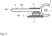
- FIG figure 5 shows a second variant of a lighting device according to the invention.
- the lighting device is shown in section and includes a variety of LED units 1, analogous to the lighting device 2 .
- the LED units are shown in the sectional view of the figure 5 arranged one behind the other perpendicular to the direction of the sheet.
- the individual LED units are in turn in direct contact with the underside 401 of the diffuser 4 .
- the light entering the diffuser via the LED units is as in the embodiment described above 2 directed to the light exit surface 403.
- a receptacle 8 is provided for a rod-shaped light guide 7, which is supplied with light via LEDs (not shown) at at least one coupling point.
- an optical reflector 5 is provided on the upper side 402 of the diffuser 4 .
- this reflector now extends only in an area above the individual LED units 1.
- a heat pipe 6 is in turn attached to the underside of the conductor track 2 for cooling the LED units 1. If necessary, the LED units can also be connected to one another discretely with lines.
- the corresponding light source (not shown) is coupled to a LIN bus in the motor vehicle at the coupling point 701 of the light rod 7 via a LIN module.
- a common processing module for all LED units 1 is preferably also located at this point, this processing module being connected via an electrical line to the conductor track 2 for data exchange with the LED units 1 and also being coupled to the LIN data bus.
- the coupling to the LIN data bus can take place at a single point, which ensures a simple construction of the lighting device.
- Control commands for controlling the LED units 1 and the light sources on the light rod 7 are transmitted from a control unit of the motor vehicle to the lighting device via the LIN bus.
- the data exchange between said processing module and the LED units takes place via an internal data bus in the form of an SPI bus, as has already been described above.
- a lighting device for a motor vehicle is created with a compact structure, since a corresponding diffuser can be placed directly in front of LED units or at a small distance.
- Light animations can also be generated in different configurations by appropriately controlling the LED units.
- a light rod can be provided in the lighting device as a further light source, with which light is also guided into the diffuser. In this way, further light effects can be achieved.
- a uniform light distribution for example in the color white, or a basic light animation can be generated by the light rod, where necessary, for example Depending on the operation or linked to certain events in the vehicle, a light animation can be switched on using different colors via appropriate control of the LED units.
Description
Die Erfindung betrifft eine Beleuchtungsvorrichtung für ein Kraftfahrzeug.The invention relates to a lighting device for a motor vehicle.
Aus dem Stand der Technik sind Beleuchtungsvorrichtungen für Kraftfahrzeuge bekannt, welche mittels LED-Einheiten verschiedene Arten von Lichtverteilungen im Innenraum sowie auch außerhalb des Fahrzeugs generieren können.Lighting devices for motor vehicles are known from the prior art, which can generate different types of light distributions in the interior as well as outside of the vehicle by means of LED units.
Um eine gleichmäßige Lichtabstrahlung zu erreichen, werden in solchen Beleuchtungsvorrichtungen häufig plattenförmige Diffusoren aus lichtstreuendem Material eingesetzt, wobei das Licht der LED-Einheiten in Richtung der Dicke des Diffusors durch diesen hindurchgeht. Dabei ist jedoch zu beachten, dass ein ausreichender Abstand zwischen dem Diffusor und den LED-Einheiten einzuhalten ist, da ansonsten die einzelnen Leuchtpunkte der LED-Einheiten sichtbar werden, wodurch das Erscheinungsbild der generierten Lichtverteilung inhomogen wird. Aufgrund des vorzusehenden Abstands zwischen Diffusor und LED-Einheiten, der mindestens bei 50% des Abstands zwischen benachbarten LED-Einheiten liegen sollte, wird sehr viel Bauraum für die Beleuchtungsvorrichtung benötigt, so dass diese für viele Anwendungen im Kraftfahrzeug, wie z.B. als Ambiente- oder Kontur-Beleuchtung, wegen beengter Platzverhältnisse nicht bzw. sehr schwer einsetzbar ist.In order to achieve uniform light emission, plate-shaped diffusers made of light-scattering material are often used in such lighting devices, with the light from the LED units passing through the diffuser in the direction of its thickness. However, it should be noted that a sufficient distance between the diffuser and the LED units must be maintained, otherwise the individual light points of the LED units will become visible, which means that the appearance of the generated light distribution will be inhomogeneous. Due to the distance to be provided between diffuser and LED units, which should be at least 50% of the distance between adjacent LED units, a lot of installation space is required for the lighting device, so that it can be used for many applications in motor vehicles, such as ambient or lighting Contour lighting, which cannot be used or is very difficult to use due to the lack of space.
Die Druckschrift
Die Druckschriften
Die Druckschrift
Aufgabe der Erfindung ist es, eine Beleuchtungsvorrichtung für ein Kraftfahrzeug mit geringen Abmessungen zu schaffen.The object of the invention is to create a lighting device for a motor vehicle with small dimensions.
Diese Aufgabe wird durch die Beleuchtungsvorrichtung gemäß Patentanspruch 1 gelöst. Weiterbildungen der Erfindung sind in den abhängigen Ansprüchen definiert.This object is achieved by the lighting device according to
Die erfindungsgemäße Beleuchtungsvorrichtung ist für ein Kraftfahrzeug, wie z.B. einen PKW oder gegebenenfalls auch einen LKW oder ein Motorrad, vorgesehen. Sie umfasst eine oder mehrere LED-Einheiten, wobei eine jeweilige LED-Einheit ein oder mehrere LEDs umfasst. Je nach Ausführungsform können die LED-Einheiten RGB-LED-Einheiten mit einer roten, grünen und blauen LED und/oder RGBW-LED-Einheiten mit einer roten, grünen, blauen und weißen LED sowie gegebenenfalls auch Weißlicht-LED-Einheiten mit einer einzelnen weißen LED oder Einfarb-LED-Einheiten mit einer einzelnen farbigen LED umfassen. In einer bevorzugten Ausführungsform kommen LED-Einheiten vom Typ APA10x bzw. WS281x und deren technische Weiterentwickungen zum Einsatz. Jedoch können ggf. auch andere LEDs verwendet werden.The lighting device according to the invention is provided for a motor vehicle, such as a passenger car or possibly also a truck or a motorcycle. It comprises one or more LED units, with each LED unit comprising one or more LEDs. Depending on the embodiment, the LED units can be RGB LED units with a red, green, and blue LED and/or RGBW LED units with a red, green, blue, and white LED, and optionally also white light LED units with a single LED white LED or single color LED units with a single colored LED. In a preferred embodiment, LED units are of the type APA10x or WS281x and their further technical developments are used. However, other LEDs can also be used if necessary.
In der erfindungsgemäßen Beleuchtungsvorrichtung ist ferner ein plattenförmiger Diffusor mit einer ersten und einer zweiten Begrenzungsfläche vorgesehen. Zwischen diesen Begrenzungsflächen befindet sich ein lichtstreuendes Material mit einer vorgegebenen Dicke. Die erste und zweite Begrenzungsfläche liegen somit in der flächigen Ausdehnung des Diffusors. Der Begriff des plattenförmigen Diffusors ist dabei weit zu verstehen, d.h. der Diffusor muss nicht zwangsläufig eine ebene Platte umfassen, sondern er kann auch als eine beliebig gebogene oder gewellte Platte ausgestaltet sein. In einer bevorzugten Variante liegt die vorgegebene Dicke im Bereich zwischen 1 mm und 5 mm.A plate-shaped diffuser with a first and a second boundary surface is also provided in the lighting device according to the invention. A light-scattering material with a predetermined thickness is located between these boundary surfaces. The first and second delimiting surfaces are therefore in the two-dimensional extent of the diffuser. The concept of the plate-shaped diffuser is to be understood broadly, i.e. the diffuser does not necessarily have to comprise a flat plate, but it can also be designed as any curved or corrugated plate. In a preferred variant, the predetermined thickness is in the range between 1 mm and 5 mm.
Die erfindungsgemäße Beleuchtungsvorrichtung weist einen plattenförmigen Diffusor aus lichtstreuendem Material mit einer ersten und zweiten Begrenzungsfläche und einer Stirnfläche des Diffusors auf. Die Stirnfläche des Diffusors, die zwischen der ersten und zweiten Begrenzungsfläche vorgesehen ist, die für einen Betrachter sichtbare Lichtaustrittsfläche und insbesondere die einzige sichtbare Lichtaustrittsfläche der Beleuchtungsvorrichtung bildet. Darüber hinaus ist die LED-Einheit bzw. sind die LED-Einheiten benachbart zur ersten Begrenzungsfläche angeordnet und strahlen im Betrieb Licht in Richtung hin zu der ersten Begrenzungsfläche ab. Dieses Licht tritt über die erste Begrenzungsfläche in den Diffusor ein. Das Licht der LED-Einheit bzw. der LED-Einheiten strahlt vorzugsweise direkt auf die erste Begrenzungsfläche, d.h. das Licht passiert keine optischen Bauteile zwischen der LED-Einheit bzw. den LED-Einheiten und der ersten Begrenzungsfläche. In einer besonders bevorzugten Variante haben die LED-Einheit oder LED-Einheiten einen Abstand von 10 mm oder weniger von der ersten Begrenzungsfläche. Vorzugsweise liegen die LED-Einheit bzw. die LED-Einheiten an der ersten Begrenzungsfläche an.The lighting device according to the invention has a plate-shaped diffuser made of light-scattering material with a first and second boundary surface and an end face of the diffuser. The front surface of the diffuser, which is provided between the first and second boundary surfaces, forms the light exit surface visible to an observer and in particular the only visible light exit surface of the lighting device. In addition, the LED unit or the LED units are/are arranged adjacent to the first boundary surface and, during operation, emit light in the direction of the first boundary surface. This light enters the diffuser via the first boundary surface. The light from the LED unit or LED units preferably shines directly onto the first boundary surface, i.e. the light does not pass through any optical components between the LED unit or LED units and the first boundary surface. In a particularly preferred variant, the LED unit or LED units are at a distance of 10 mm or less from the first boundary surface. The LED unit or the LED units are preferably in contact with the first boundary surface.
Der Diffusor der erfindungsgemäßen Beleuchtungsvorrichtung ist derart ausgestaltet und angeordnet, dass zumindest ein Teil des über die erste Begrenzungsfläche eintretenden Lichts der LED-Einheit oder LED-Einheiten im Diffusor bis zu der Lichtaustrittsfläche geleitet wird und dort aus der Beleuchtungsvorrichtung austritt. Die Lichtleitung im Diffusor erfolgt dabei über Reflexionen an der ersten und zweiten Begrenzungsfläche.The diffuser of the lighting device according to the invention is designed and arranged in such a way that at least part of the light entering via the first boundary surface of the LED unit or LED units is guided in the diffuser to the light exit surface and exits the lighting device there. The light is guided in the diffuser via reflections on the first and second boundary surfaces.
Die erfindungsgemäße Beleuchtungsvorrichtung weist den Vorteil auf, dass durch einen Lichtaustritt an einer Stirnfläche des Diffusors und damit in anderer Richtung als der Lichteintritt eine sehr kompakte Bauweise der Beleuchtungsvorrichtung erreicht wird. Die Beleuchtungsvorrichtung kann somit auch in Bereichen des Kraftfahrzeugs verbaut werden, in denen beengte Platzverhältnisse vorliegen, wie z.B. in Türverkleidungen, Instrumententafeln, Mittelkonsolen und dergleichen. Durch die Lichtverteilung im Diffusor wird ferner die Generierung einer homogenen Lichtverteilung erreicht.The lighting device according to the invention has the advantage that a very compact design of the lighting device is achieved by light exiting at an end face of the diffuser and thus in a different direction than the light entry. The lighting device can thus also be installed in areas of the motor vehicle where space is limited, such as in door panels, instrument panels, center consoles and the like. Furthermore, the generation of a homogeneous light distribution is achieved by the light distribution in the diffuser.
In einer besonders bevorzugten Ausführungsform sind für die LED-Einheit bzw. LED-Einheiten eine Hauptstrahlrichtung vorgegeben, bezogen auf welche die jeweilige LED-Einheit symmetrisch Licht abstrahlt. Vorzugsweise ist die Hauptstrahlrichtung einer jeweiligen LED-Einheit im Wesentlichen senkrecht zur ersten Begrenzungsfläche am Ort des Eintritts des Lichts der jeweiligen LED-Einheit in die erste Begrenzungsfläche.In a particularly preferred embodiment, a main beam direction is specified for the LED unit or LED units, based on which the respective LED unit emits light symmetrically. The main beam direction of a respective LED unit is preferably essentially perpendicular to the first delimiting surface at the point at which the light of the respective LED unit enters the first delimiting surface.
In einer weiteren Variante der erfindungsgemäßen Beleuchtungsvorrichtung umfasst der plattenförmige Diffusor eine weitere Stirnfläche, welche an einem entfernt zu der Lichtaustrittsfläche liegenden Ende des Diffusors angeordnet ist, wobei die LED-Einheit oder LED-Einheiten benachbart zu der weiteren Stirnfläche angeordnet sind. Auf diese Weise wird sichergestellt, dass das Licht im Diffusor einen langen Weg zurücklegt, so dass die generierte Lichtverteilung an der Lichtaustrittsfläche besonders homogen ist.In a further variant of the lighting device according to the invention, the plate-shaped diffuser comprises a further end face which is arranged at an end of the diffuser remote from the light exit surface, the LED unit or LED units being arranged adjacent to the further end face. This ensures that the light travels a long way in the diffuser, so that the light distribution generated on the light exit surface is particularly homogeneous.
In einer weiteren, besonders bevorzugten Variante der erfindungsgemäßen Beleuchtungsvorrichtung stellt der Diffusor einen Streifen dar und die Lichtaustrittsfläche ist eine Längskante des Streifens, wobei die Beleuchtungsvorrichtung vorzugsweise mehrere LED-Einheiten umfasst, welche in Richtung der Längsrichtung des Streifens nebeneinander angeordnet sind. Je nach verwendeten LED-Einheiten können diese mit unterschiedlicher Packungsdichte und damit unterschiedlichem Abstand zueinander entlang des Streifens positioniert sein. Insbesondere können Packungsdichten je nach LED-Baugröße von z.B. 144 - 367 LED-Einheiten pro Meter erreicht werden, was einem Abstand der LED-Einheiten von etwa 7 mm und weniger entspricht. Die Packungsdichten können jedoch auch geringer sein und beispielsweise bei 72 oder 60 oder 30 LED-Einheiten pro Meter liegen.In a further, particularly preferred variant of the lighting device according to the invention, the diffuser represents a strip and the light exit surface is a longitudinal edge of the strip, the lighting device preferably comprising a plurality of LED units which are arranged next to one another in the direction of the longitudinal direction of the strip. Depending on the LED units used, they can be positioned along the strip with different packing densities and thus different distances from one another. In particular, depending on the size of the LED, packing densities of, for example, 144-367 LED units per meter can be achieved, which corresponds to a distance between the LED units of around 7 mm and less. However, the packing densities can also be lower and can be, for example, 72 or 60 or 30 LED units per meter.
In einer besonders bevorzugten Variante der soeben beschriebenen Ausführungsform liegt die Breite des als Streifen ausgebildeten Diffusors zwischen 40% und 250%, insbesondere zwischen 50% und 200%, des (konstanten) Abstands zwischen benachbarten LEDs. Je größer die Breite des Streifens ist, desto homogener ist die erzeugte Lichtverteilung.In a particularly preferred variant of the embodiment just described, the width of the diffuser designed as a strip is between 40% and 250%, in particular between 50% and 200%, of the (constant) distance between adjacent LEDs. The greater the width of the strip, the more homogeneous the light distribution generated.
In einer weiteren Ausgestaltung der erfindungsgemäßen Beleuchtungsvorrichtung ist an der zweiten Begrenzungsfläche des Diffusors zumindest in dem Bereich, welcher der oder den LED-Einheiten gegenüberliegt, ein optischer Reflektor angeordnet. Auf diese Weise werden die Lichtverluste im Diffusor gering gehalten. Der optische Reflektor kann gegebenenfalls ein Teil einer Verkleidung des Kraftfahrzeugs sein. Ferner kann der Reflektor gegebenenfalls auch die gesamte zweite Begrenzungsfläche abdecken.In a further embodiment of the lighting device according to the invention, an optical reflector is arranged on the second boundary surface of the diffuser, at least in the area which is opposite the LED unit or units. In this way, the light losses in the diffuser are kept low. The optical reflector can optionally be part of a paneling of the motor vehicle. Furthermore, the reflector can optionally also cover the entire second boundary surface.
Die erfindungsgemäße Beleuchtungsvorrichtung kann je nach Ausgestaltung eine Innenraumbeleuchtung im Kraftfahrzeug oder auch eine Außenbeleuchtung an der Außenseite des Kraftfahrzeugs sein. Demzufolge kann der soeben beschriebene Reflektor beispielsweise Teil einer Innenraumverkleidung des Kraftfahrzeugs sein.Depending on the configuration, the lighting device according to the invention can be an interior light in the motor vehicle or also an external light on the outside of the motor vehicle. Accordingly, the reflector just described can be part of an interior paneling of the motor vehicle, for example.
In einer weiteren Variante der Erfindung sind die LED-Einheit oder LED-Einheiten auf einer Wärmeableitung, z.B. einem Kühlkörper, angeordnet. Hierdurch wird eine effiziente Abfuhr der durch die LED-Einheiten erzeugten Wärme auch bei kleinem Bauraum gewährleistet.In a further variant of the invention, the LED unit or LED units are arranged on a heat sink, e.g. This ensures efficient dissipation of the heat generated by the LED units, even with a small installation space.
In einer weiteren Variante umfasst die erfindungsgemäße Beleuchtungsvorrichtung mehrere LED-Einheiten, welche auf einer gemeinsamen Leiterplatte bzw. Leiterbahn angeordnet sind. Im Falle, dass eine Wärmeableitung vorgesehen ist, kann diese beispielsweise auf einer Seite der gemeinsamen Leiterbahn ausgebildet sein.In a further variant, the lighting device according to the invention comprises a number of LED units which are arranged on a common printed circuit board or conductor track. If a heat dissipation is provided, this can be formed, for example, on one side of the common conductor track.
In einer weiteren Variante umfasst die erfindungsgemäße Beleuchtungsvorrichtung ferner einen stabförmigen Lichtleiter, z.B. einen zylindrischen Lichtleiter. Dabei sind an einem oder beiden Enden des stabförmigen Lichtleiters eine oder mehrere Lichtquellen, z.B. LEDs, zur Einspeisung von Licht in den stabförmigen Lichtleiter vorgesehen. Das eingespeiste Licht tritt entlang der Längsrichtung des stabförmigen Lichtleiters aus diesem aus und der stabförmige Lichtleiter ist derart am Diffusor angeordnet, dass das aus ihm austretende Licht in den Diffusor eintritt und dort zur Lichtaustrittsfläche geleitet wird. Diese Variante der Erfindung ermöglicht eine zusätzliche Generierung von Licht mittels eines stabförmigen Lichtleiters. Mit einer derartigen Beleuchtungsvorrichtung können viele unterschiedliche Lichteffekte erzeugt werden. Insbesondere kann über den stabförmigen Lichtleiter Weißlicht generiert werden, welches dann mit geeigneten farbigen Animationen überlagert wird, die mit den LED-Einheiten benachbart zur ersten Begrenzungsfläche generiert werden.In a further variant, the lighting device according to the invention also comprises a rod-shaped light guide, for example a cylindrical light guide. In this case, one or more light sources, for example LEDs, are provided at one or both ends of the rod-shaped light guide for feeding light into the rod-shaped light guide. The light fed in emerges from the rod-shaped light guide along the longitudinal direction thereof and the rod-shaped light guide is arranged on the diffuser in such a way that the light emerging from it Light enters the diffuser and is directed there to the light exit surface. This variant of the invention enables additional generation of light by means of a rod-shaped light guide. Many different light effects can be produced with such a lighting device. In particular, white light can be generated via the rod-shaped light guide, which is then overlaid with suitable colored animations that are generated with the LED units adjacent to the first boundary surface.
In einer bevorzugten Variante der soeben beschriebenen Ausführungsform ist zumindest eine Lichtquelle, welche an einem Ende des stabförmigen Lichtleiters Licht einspeist, über ein Schnittstellen-Modul an einen Kraftfahrzeug-Datenbus angebunden, wobei sich am Ort des Schnittstellen-Moduls ferner ein Verarbeitungsmodul befindet, welches mit der oder den LED-Einheiten elektrisch verbunden ist und ebenfalls an den Kraftfahrzeug-Datenbus angebunden ist. Hierdurch wird der Aufbau der erfindungsgemäßen Beleuchtungsvorrichtung stark vereinfacht. Der Kraftfahrzeug-Datenbus ist vorzugsweise ein LIN-Bus (LIN = Local Interconnect Network). Gegebenenfalls kann der Kraftfahrzeug-Datenbus auch ein CAN-Bus (CAN = Controller Area Network) oder ein anderer Datenbus sein.In a preferred variant of the embodiment just described, at least one light source, which feeds light at one end of the rod-shaped light guide, is connected to a motor vehicle data bus via an interface module, with a processing module also being located at the location of the interface module, which which or the LED units is electrically connected and is also connected to the motor vehicle data bus. This greatly simplifies the structure of the lighting device according to the invention. The motor vehicle data bus is preferably a LIN bus (LIN=Local Interconnect Network). If necessary, the motor vehicle data bus can also be a CAN bus (CAN=Controller Area Network) or another data bus.
In einer weiteren Variante der erfindungsgemäßen Beleuchtungsvorrichtung umfassen die LED-Einheit oder LED-Einheiten jeweils eine integrierte Schaltung zur Ansteuerung des oder der LEDs der jeweiligen LED-Einheit. Vorzugsweise sind die LEDs und die integrierte Schaltung dabei in einem gemeinsamen Gehäuse untergebracht, so dass die LED-Einheiten sehr kompakt sind. Insbesondere können die LED-Einheiten den oben genannten Typen APA10x bzw. WS281x und deren technischen Weiterentwickungen entsprechen.In a further variant of the lighting device according to the invention, the LED unit or LED units each comprise an integrated circuit for driving the LED or LEDs of the respective LED unit. The LEDs and the integrated circuit are preferably housed in a common housing, so that the LED units are very compact. In particular, the LED units can correspond to the types APA10x or WS281x mentioned above and their further technical developments.
In einer weiteren Variante umfasst die erfindungsgemäße Beleuchtungsvorrichtung mehrere LED-Einheiten, welche über einen internen Datenbus mit einem gemeinsamen Verarbeitungsmodul gekoppelt sind, wobei das Verarbeitungsmodul zur Kopplung an einen Kraftfahrzeug-Datenbus und insbesondere an einen LIN-Datenbus eingerichtet ist, um erste digitale Steuerbefehle zum Betrieb der Beleuchtungsvorrichtung von dem Kraftfahrzeug-Datenbus zu empfangen und als zweite digitale Steuerbefehle auf den internen Datenbus zu geben, und wobei die LED-Einheiten dazu eingerichtet sind, ihren LEDs Strom aus einer Spannungsversorgung basierend auf den zweiten digitalen Steuerbefehlen auf dem internen Datenbus mittels der integrierten Schaltungen zuzuführen.In a further variant, the lighting device according to the invention comprises a plurality of LED units which are coupled to a common processing module via an internal data bus, the processing module being set up for coupling to a motor vehicle data bus and in particular to a LIN data bus in order to transmit first digital control commands for To receive operation of the lighting device from the motor vehicle data bus and to give second digital control commands to the internal data bus, and the LED units are set up to their LEDs supply current from a voltage supply based on the second digital control commands on the internal data bus by means of the integrated circuits.
In einer bevorzugten Variante der soeben beschriebenen Ausführungsform ist der interne Datenbus ein SPI-Datenbus (SPI = Serial Protocol Interface). Das Verarbeitungsmodul kann dabei derart ausgestaltet sein, dass die ersten digitalen Steuersignale mittels Software-SPI und/oder Hardware-SPI auf den SPI-Bus gegeben werden. Die Software-SPI-Methode ist an sich aus dem Stand der Technik bekannt und ermöglicht mittels einer Programmbibliothek ein ausführbares Programm auf dem entsprechenden Verarbeitungsmodul zu erzeugen, mit dem jedes Pin des Verarbeitungsmoduls als SPI-Pin zur Verbindung mit Leitungen des SPI-Busses konfiguriert werden kann. Mit anderen Worten werden bei der Verwendung von Software-SPI herkömmliche I/O-Pins als SPI-Pins konfiguriert. Im Gegensatz dazu sind bei der Verwendung von Hardware-SPI dedizierte PINs des Verarbeitungsmoduls zur Anbindung an den SPI-Bus vorgesehen.In a preferred variant of the embodiment just described, the internal data bus is an SPI data bus (SPI=Serial Protocol Interface). The processing module can be designed in such a way that the first digital control signals are sent to the SPI bus by means of software SPI and/or hardware SPI. The software SPI method is known per se from the prior art and enables an executable program to be generated on the corresponding processing module using a program library, with which each pin of the processing module can be configured as an SPI pin for connection to lines of the SPI bus can. In other words, when using software SPI, traditional I/O pins are configured as SPI pins. In contrast, when using hardware SPI, dedicated processing module pins are provided for connection to the SPI bus.
Anstatt eines SPI-Datenbusses kann als interner Datenbus auch ein differentieller Datenbus verwendet werden, wobei sich ein differentieller Datenbus dadurch auszeichnet, dass digitale Daten über eine Spannungsdifferenz zwischen zwei Leitungen codiert werden. In einer Variante wird als differentieller Datenbus der an sich bekannte APIX-Bus (APIX = Automotive Pixel Link) verwendet.Instead of an SPI data bus, a differential data bus can also be used as the internal data bus, a differential data bus being characterized in that digital data is encoded via a voltage difference between two lines. In one variant, the APIX bus (APIX=Automotive Pixel Link), which is known per se, is used as the differential data bus.
In einer weiteren Variante der obigen Ausführungsform sind die LED-Einheiten jeweils dazu eingerichtet, der oder den LEDs der jeweiligen LED-Einheit Strom aus der Spannungsversorgung über PWM-Modulation zuzuführen. Gegebenenfalls kann der Strom aus der Spannungsversorgung auch über die Einstellung variabler Strompegel zugeführt werden.In a further variant of the above embodiment, the LED units are each set up to supply current from the voltage supply via PWM modulation to the LED or LEDs of the respective LED unit. If necessary, the current from the power supply can also be supplied by setting variable current levels.
Neben der soeben beschriebenen Beleuchtungsvorrichtung betrifft die Erfindung ein Kraftfahrzeug, insbesondere einen PKW oder gegebenenfalls auch einen LKW oder ein Motorrad, das eine oder mehrere der erfindungsgemäßen Beleuchtungsvorrichtungen bzw. bevorzugter Varianten dieser Beleuchtungsvorrichtungen umfasst.In addition to the lighting device just described, the invention relates to a motor vehicle, in particular a passenger car or possibly also a truck or a motorcycle, which includes one or more of the lighting devices according to the invention or preferred variants of these lighting devices.
Ausführungsbeispiele der Erfindung werden nachfolgend anhand der beigefügten Figuren detailliert beschrieben.Exemplary embodiments of the invention are described in detail below with reference to the accompanying figures.
Es zeigen:
- Fig. 1
- eine Schnittansicht einer Beleuchtungsvorrichtung gemäß dem Stand der Technik;
- Fig. 2
- eine Schnittansicht einer Ausführungsform einer erfindungsgemäßen Beleuchtungsvorrichtung;
- Fig. 3
- eine Draufsicht auf die Beleuchtungsvorrichtung der
Fig. 2 ; - Fig. 4
- eine perspektivische Ansicht einer Beleuchtungsvorrichtung nach dem Stand der Technik mit Lichtleiter-Einspeisung; und
- Fig. 5
- eine Schnittansicht einer weiteren Ausführungsform einer erfindungsgemäßen Beleuchtungsvorrichtung, welche die Lichtleiter-Einspeisung gemäß
Fig. 4 enthält.
- 1
- a sectional view of a lighting device according to the prior art;
- 2
- a sectional view of an embodiment of a lighting device according to the invention;
- 3
- a plan view of the lighting device of FIG
2 ; - 4
- a perspective view of a lighting device according to the prior art with optical fiber feed; and
- figure 5
- a sectional view of a further embodiment of a lighting device according to the invention, which the light guide feed according to
4 contains.
Vor den LED-Einheiten 1 ist ein plattenförmiger Diffusor 4 angeordnet, der das Licht der LED-Einheiten streut. Die Dicke des Diffusors ist mit d bezeichnet. Als Material für den Diffusor kann an sich bekanntes lichtstreuendes Material, wie Opal, Milchglas oder Kunststoff (Polyamid, Polycarbonat, Polymethylmethacrylat und dergleichen), eingesetzt werden. Der plattenförmige Diffusor 4 umfasst eine Unterseite 401 und eine Oberseite 402. Die flächige Ausdehnung des Diffusors verläuft dabei senkrecht zu den Hauptstrahlrichtungen HS der LED-Einheiten 1. Bezogen auf diese Hauptstrahlrichtungen strahlen die jeweiligen LED-Einheiten symmetrisch ab.In front of the
In der Anordnung der
Zur Lösung dieser Problematik wird eine Beleuchtungsvorrichtung verwendet, bei der - im Gegensatz zu herkömmlichen Beleuchtungsvorrichtungen - der Lichteintritt in den Diffusor in eine andere Richtung als der Lichtaustritt erfolgt.
Im Unterschied zu
Die Abmessungen des Diffusors 4 und die Anordnung der LED-Einheiten 1 werden aus der Draufsicht der
In der Ausführungsform der
Der in
Die bekannte Beleuchtungsvorrichtung aus
Zur Verminderung von Lichtverlusten ist in der Ausführungsform der
In einer bevorzugten Variante der Ausführungsform der
Die im Vorangegangenen beschriebenen Ausführungsformen der Erfindung weisen eine Reihe von Vorteilen auf. Insbesondere wird eine Beleuchtungsvorrichtung für ein Kraftfahrzeug mit einem kompakten Aufbau geschaffen, da ein entsprechender Diffusor direkt bzw. mit geringem Abstand vor LED-Einheiten platziert werden kann. Über die entsprechende Ansteuerung der LED-Einheiten können ferner Lichtanimationen in unterschiedlicher Ausgestaltung erzeugt werden. Gegebenenfalls kann in der Beleuchtungsvorrichtung als weiteres Leuchtmittel ein Lichtstab vorgesehen sein, mit dem ebenfalls Licht in den Diffusor geleitet wird. Auf diese Weise können weitere Lichteffekte erreicht werden. Insbesondere kann durch den Lichtstab eine gleichmäßige Lichtverteilung, z.B. in der Farbe Weiß, oder eine Basis-Lichtanimation erzeugt werden, wobei bedarfsweise, beispielsweise je nach Bedienung bzw. gekoppelt an bestimmte Ereignisse im Fahrzeug, eine Lichtanimation mittels unterschiedlicher Farben über entsprechende Ansteuerung der LED-Einheiten hinzugeschaltet werden kann.The embodiments of the invention described above have a number of advantages. In particular, a lighting device for a motor vehicle is created with a compact structure, since a corresponding diffuser can be placed directly in front of LED units or at a small distance. Light animations can also be generated in different configurations by appropriately controlling the LED units. If necessary, a light rod can be provided in the lighting device as a further light source, with which light is also guided into the diffuser. In this way, further light effects can be achieved. In particular, a uniform light distribution, for example in the color white, or a basic light animation can be generated by the light rod, where necessary, for example Depending on the operation or linked to certain events in the vehicle, a light animation can be switched on using different colors via appropriate control of the LED units.
- 11
- LED-EinheitLED unit
- 22
- Leiterbahntrace
- 33
- integrierte Schaltungintegrated circuit
- 44
- Diffusordiffuser
- 401401
- Unterseite des Diffusorsunderside of the diffuser
- 402402
- Oberseite des Diffusorstop of the diffuser
- 403, 404403, 404
- Stirnflächen des Diffusorsfaces of the diffuser
- 55
- optischer Reflektoroptical reflector
- 66
- Wärmeableitungheat dissipation
- 77
- Lichtstablightstick
- 701, 702701, 702
- Einkoppelstellen des LichtstabsCoupling points of the light rod
- 88th
- AufnahmeRecording
- di.e
- Dicke des Diffusorsthickness of the diffuser
- dDIdDI
- Abstand zwischen LED-Einheiten und Unterseite des DiffusorsDistance between LED units and bottom of diffuser
- d'd'
- Abstand zwischen Leiterbahn und Unterseite des DiffusorsDistance between trace and underside of diffuser
- dDI'dDI'
- Abstand zwischen LED-Einheiten und Stirnfläche des DiffusorsDistance between LED units and the face of the diffuser
- dLEDdLED
- Abstand zwischen den LED-EinheitenDistance between the LED units
- HSHS
- Hauptstrahlrichtung der LED-EinheitenMain beam direction of the LED units
Claims (16)
- Lighting apparatus for a motor vehicle, comprising one or more LED units (1), wherein a respective LED unit (1) comprises one or more LEDs;a plate-shaped diffuser (4) consisting of light-scattering material and having a first and second delimiting face (401, 402);whereinan end face of the diffuser (4) which is provided between the first delimiting face (401) and the second delimiting face (402) forms the light emergence face (403) of the lighting apparatus that is visible to a user;the LED unit (1) or LED units (1) are arranged adjacent to the first delimiting face (401) and, during operation, emit light in the direction of the first delimiting face (401), said light entering into the diffuser (4) via the first delimiting face (401);the diffuser (4) is configured and arranged in such a way that at least some of the light of the LED unit (1) or LED units (1) entering via the first delimiting face (401) is guided in the diffuser (4) to the light emergence face (403) and it emerges from the lighting apparatus there.
- Lighting apparatus according to Claim 1, characterized in that the LED unit (1) or LED units (1) have a distance of 10 mm or less from the first delimiting face (401) and, in particular, abut against the first delimiting face (401).
- Lighting apparatus according to either of the preceding claims, characterized in that a principal emission direction (HS) is predetermined for the LED unit (1) or LED units (1), the respective LED unit (1) emitting light symmetrically in respect of said principal emission direction, wherein the principal emission direction (HS) of a respective LED unit (1) is preferably substantially perpendicular to the first delimiting face (401) at the location where the light of the respective LED unit (1) enters into the first delimiting face (401).
- Lighting apparatus according to any one of the preceding claims, characterized in that the diffuser (4) has a further end face (404) which is arranged at an end of the diffuser (4) that is distant from the light emergence face (403), wherein the LED unit (1) or LED units (1) are arranged adjacent to the further end face (404).
- Lighting apparatus according to any one of the preceding claims, characterized in that the diffuser (4) represents a strip and the light emergence face (403) is a longitudinal edge of the strip, wherein the lighting apparatus preferably comprises a plurality of LED units (1) that are arranged next to one another in the direction of the longitudinal edge of the strip.
- Lighting apparatus according to Claim 5, characterized in that the width of the strip lies between 40% and 250%, in particular between 50% and 200%, of the distance between adjacent LED units (1) .
- Lighting apparatus according to any one of the preceding claims, characterized in that an optical reflector (5) is arranged at the second delimiting face (402) of the diffuser (4), at least in the region which lies opposite the LED unit or units (1) .
- Lighting apparatus according to Claim 7, characterized in that the optical reflector (5) is part of a trim of the motor vehicle.
- Lighting apparatus according to any one of the preceding claims, characterized in that the lighting apparatus is an interior lighting in the motor vehicle or an exterior lighting on the outside of the motor vehicle.
- Lighting apparatus according to any one of the preceding claims, characterized in that the LED unit (1) or LED units (1) are arranged on a heatsink (6).
- Lighting apparatus according to any one of the preceding claims, characterized in that the lighting apparatus comprises a plurality of LED units (1) which are arranged on a common conductor track (2).
- Lighting apparatus according to any one of the preceding claims, characterized in that the lighting apparatus further comprises a rod-shaped light guide (7), wherein provision is made at one or both ends (701, 702) of the rod-shaped light guide (7) for one or more light sources for feeding light into the rod-shaped light guide (7), wherein the fed light emerges from the rod-shaped light guide (7) along the longitudinal direction of same and the rod-shaped light guide (7) is arranged on the diffuser (4) in such a way that the light emerging from said rod-shaped light guide enters into the diffuser (4) and it is guided there to the light emergence face (403) .
- Lighting apparatus according to Claim 12, characterized in that at least one light source, which feeds light at one end of the rod-shaped light guide (7), is able to be connected to a motor vehicle data bus via an interface module, wherein, further, a processing module is situated at the location of the interface module, said processing module being electrically connected to the LED unit or units (1) and likewise being able to be connected to the motor vehicle data bus.
- Lighting apparatus according to any one of the preceding claims, characterized in that the LED unit (1) or LED units (1) each comprise an integrated circuit for actuating the LED or LEDs of the respective LED unit (1).
- Lighting apparatus according to Claim 14, characterized in that the lighting apparatus comprises a plurality of LED units (1) which are coupled to a common processing module by way of an internal data bus, wherein the processing module is configured to be coupled to a motor vehicle data bus in order to receive first digital control commands for operating the lighting apparatus from the motor vehicle data bus and to forward these to the internal data bus as second digital control commands, and wherein the LED units (1) are configured to feed power from a voltage supply to their LEDs on the basis of the second digital control commands on the internal data bus by means of the integrated circuits, wherein the internal data bus is preferably an SPI bus or a differential data bus.
- Motor vehicle, comprising one or more lighting apparatuses according to any one of the preceding claims.
Applications Claiming Priority (2)
| Application Number | Priority Date | Filing Date | Title |
|---|---|---|---|
| DE102015222505.4A DE102015222505A1 (en) | 2015-11-16 | 2015-11-16 | Lighting device for a motor vehicle |
| PCT/EP2016/075494 WO2017084836A1 (en) | 2015-11-16 | 2016-10-24 | Illumination device for a motor vehicle |
Publications (2)
| Publication Number | Publication Date |
|---|---|
| EP3377370A1 EP3377370A1 (en) | 2018-09-26 |
| EP3377370B1 true EP3377370B1 (en) | 2023-07-05 |
Family
ID=57200003
Family Applications (1)
| Application Number | Title | Priority Date | Filing Date |
|---|---|---|---|
| EP16785467.8A Active EP3377370B1 (en) | 2015-11-16 | 2016-10-24 | Illumination device for a motor vehicle |
Country Status (5)
| Country | Link |
|---|---|
| US (1) | US11447069B2 (en) |
| EP (1) | EP3377370B1 (en) |
| CN (1) | CN107921908B (en) |
| DE (1) | DE102015222505A1 (en) |
| WO (1) | WO2017084836A1 (en) |
Families Citing this family (6)
| Publication number | Priority date | Publication date | Assignee | Title |
|---|---|---|---|---|
| WO2018119344A1 (en) * | 2016-12-22 | 2018-06-28 | Flex-N-Gate Advanced Product Development, Llc | Homogenous led vehicle lamp |
| DE102018202127A1 (en) | 2017-04-11 | 2018-10-11 | Volkswagen Aktiengesellschaft | Lighting device for generating an ambient light in the interior of a motor vehicle |
| DE102017107969A1 (en) * | 2017-04-12 | 2018-10-18 | Lisa Dräxlmaier GmbH | Lighting device for an interior trim part of a motor vehicle |
| DE102017211659A1 (en) | 2017-07-07 | 2019-01-10 | Bayerische Motoren Werke Aktiengesellschaft | Lighting unit for a vehicle and method for its manufacture |
| US10672327B1 (en) | 2019-01-02 | 2020-06-02 | Jvis-Usa, Llc | Low-profile display assembly for a vehicle and configured to display computer-generated imagery at the front of the assembly |
| US11766972B2 (en) | 2019-01-02 | 2023-09-26 | Jvis-Usa, Llc | Low-profile, backlit, panel assembly for displaying images and/or data within a passenger compartment of a vehicle |
Citations (3)
| Publication number | Priority date | Publication date | Assignee | Title |
|---|---|---|---|---|
| DE102010030660A1 (en) * | 2010-06-29 | 2011-12-29 | Lisa Dräxlmaier GmbH | Illuminated vehicle interior part |
| WO2014179824A1 (en) * | 2013-05-08 | 2014-11-13 | Zizala Lichtsysteme Gmbh | Lighting system for motor vehicles |
| US20150198319A1 (en) * | 2013-11-21 | 2015-07-16 | Ford Glaobal Technologies, LLC | Photoluminescent dynamic lighting |
Family Cites Families (32)
| Publication number | Priority date | Publication date | Assignee | Title |
|---|---|---|---|---|
| US5197792A (en) * | 1992-04-21 | 1993-03-30 | General Motors Corporation | Illuminator device for a display panel |
| DE102004015544B4 (en) * | 2003-03-31 | 2009-05-07 | Toyoda Gosei Co., Ltd. | LED light and side mirror device |
| DE102005003132B8 (en) * | 2004-08-13 | 2010-07-22 | F.S. Fehrer Automotive Gmbh | Component with hard foam body and electrical and / or electronic functional element |
| DE202007016755U1 (en) * | 2006-05-11 | 2008-02-14 | Schefenacker Patents S.à.r.l. | Exterior mirror with a light unit |
| FR2916257B1 (en) * | 2007-05-15 | 2012-12-14 | Valeo Vision | SIGNALING OR LIGHTING DEVICE FOR MOTOR VEHICLE |
| FR2928110B1 (en) * | 2008-03-03 | 2010-06-11 | Valeo Vision | OPTICAL SYSTEM WITH MAIN FUNCTION FOR MOTOR VEHICLE |
| US8258702B2 (en) * | 2008-05-21 | 2012-09-04 | Ford Global Technologies, Llc | Ambient LED lighting system and method |
| US8162519B2 (en) * | 2009-02-22 | 2012-04-24 | Ford Global Technologies, Llc | Concealed interior lighting for automobiles |
| FR2962704B1 (en) * | 2010-07-16 | 2013-05-17 | Valeo Vision | DEVICE FOR LIGHTING AND / OR SIGNALING A MOTOR VEHICLE |
| FR2967235B1 (en) * | 2010-11-05 | 2014-10-31 | Valeo Vision | LIGHTING OR SIGNALING DEVICE FOR A MOTOR VEHICLE HAVING A LIGHT GUIDE RAIL. |
| DE102011016402A1 (en) * | 2011-04-08 | 2012-10-11 | GM Global Technology Operations LLC (n. d. Gesetzen des Staates Delaware) | Vehicle taillight for motor vehicle e.g. motor car, has illumination unit that is linked to edge surface of layers of fiber optic material having volume distributed diffusing nanoparticles |
| US8746939B2 (en) * | 2011-11-07 | 2014-06-10 | Ford Global Technologies, Llc | Crystal off-axis LED headlamp |
| DE102011089481A1 (en) * | 2011-12-21 | 2013-06-27 | Automotive Lighting Reutlingen Gmbh | Automotive lighting device with a long and flat luminous surface |
| DE102012005399A1 (en) * | 2012-03-16 | 2013-09-19 | Audi Ag | Lighting device, in particular contour lighting for a motor vehicle |
| DE102012107437B4 (en) * | 2012-08-14 | 2022-04-28 | HELLA GmbH & Co. KGaA | lighting device |
| EP2902694B1 (en) * | 2012-09-27 | 2020-11-04 | LG Innotek Co., Ltd. | Illuminating device and vehicle lamp comprising same |
| DE102012109898A1 (en) * | 2012-10-17 | 2014-04-17 | Webasto SE | Glazing component for illumination system, has flat plate for illuminating inner space, where light is coupled to front side of plate with two planar regions connected to each other, which are provided with light-conducting materials |
| FR2998678B1 (en) * | 2012-11-29 | 2016-01-08 | Valeo Vision | LIGHT GUIDE FOR AN OPTICAL DEVICE, IN PARTICULAR LIGHTING AND / OR SIGNALING |
| DE102012112152A1 (en) * | 2012-12-12 | 2014-06-12 | Dr. Ing. H.C. F. Porsche Aktiengesellschaft | Motor vehicle tail lamp for use with multiple light functions, has light guides with legs, on which output couplers are formed, where light emission segments are protruded in output couplers |
| WO2014098436A1 (en) * | 2012-12-17 | 2014-06-26 | 엘지이노텍 주식회사 | Lighting unit for vehicle |
| DE112014000694T5 (en) * | 2013-02-06 | 2015-10-22 | Innotec, Corp. | Make-up lighting and actuation arrangement for sun visors of vehicles |
| DE102013202282A1 (en) * | 2013-02-13 | 2014-08-14 | Continental Automotive Gmbh | Light source and method for producing the light source |
| ITPD20130075A1 (en) * | 2013-03-25 | 2014-09-26 | Automotive Lighting Italia Spa | LIGHTING AND / OR SIGNALING DEVICE FOR VEHICLES AND ITS CONSTRUCTION METHOD |
| DE102013007938B4 (en) * | 2013-05-07 | 2019-05-23 | Motherson Innovations Lights GmbH & Co. KG | Flexible light guide and method of making a flexible light guide |
| DE102014206238A1 (en) * | 2013-06-22 | 2014-12-24 | Volkswagen Aktiengesellschaft | Motor vehicle with a lighting device |
| JP5968276B2 (en) * | 2013-07-30 | 2016-08-10 | 株式会社東海理化電機製作所 | Mirror device for vehicle |
| ITTV20130134A1 (en) * | 2013-08-19 | 2015-02-20 | Automotive Lighting Italia Spa | AUTOMOTIVE HEADLIGHT |
| JP5726973B2 (en) * | 2013-09-27 | 2015-06-03 | 本田技研工業株式会社 | Lighting equipment |
| JP6249556B2 (en) * | 2013-10-23 | 2017-12-20 | 株式会社小糸製作所 | Vehicle lamp |
| CN104235726A (en) * | 2014-08-28 | 2014-12-24 | 马瑞利汽车零部件(芜湖)有限公司 | LED (light emitting diode) automobile signal lamp |
| US9651211B2 (en) * | 2014-10-16 | 2017-05-16 | Valeo North America, Inc. | Multi-function optical system with shared exit optic |
| EP3076069B1 (en) * | 2015-03-31 | 2020-03-11 | Seoul Semiconductor Co., Ltd. | Light device of vehicle |
-
2015
- 2015-11-16 DE DE102015222505.4A patent/DE102015222505A1/en active Pending
-
2016
- 2016-10-24 EP EP16785467.8A patent/EP3377370B1/en active Active
- 2016-10-24 WO PCT/EP2016/075494 patent/WO2017084836A1/en active Application Filing
- 2016-10-24 CN CN201680046951.XA patent/CN107921908B/en active Active
-
2018
- 2018-05-15 US US15/980,443 patent/US11447069B2/en active Active
Patent Citations (3)
| Publication number | Priority date | Publication date | Assignee | Title |
|---|---|---|---|---|
| DE102010030660A1 (en) * | 2010-06-29 | 2011-12-29 | Lisa Dräxlmaier GmbH | Illuminated vehicle interior part |
| WO2014179824A1 (en) * | 2013-05-08 | 2014-11-13 | Zizala Lichtsysteme Gmbh | Lighting system for motor vehicles |
| US20150198319A1 (en) * | 2013-11-21 | 2015-07-16 | Ford Glaobal Technologies, LLC | Photoluminescent dynamic lighting |
Also Published As
| Publication number | Publication date |
|---|---|
| CN107921908A (en) | 2018-04-17 |
| DE102015222505A1 (en) | 2017-05-18 |
| EP3377370A1 (en) | 2018-09-26 |
| CN107921908B (en) | 2021-11-09 |
| US20180257557A1 (en) | 2018-09-13 |
| WO2017084836A1 (en) | 2017-05-26 |
| US11447069B2 (en) | 2022-09-20 |
Similar Documents
| Publication | Publication Date | Title |
|---|---|---|
| EP3377370B1 (en) | Illumination device for a motor vehicle | |
| EP3538812B1 (en) | Illumination device, in particular for a motor vehicle | |
| DE102018119334B4 (en) | LIGHTING DEVICE AND/OR SIGNALING DEVICE FOR A MOTOR VEHICLE | |
| EP2444283B1 (en) | Light module | |
| DE102007043903A1 (en) | Luminous device | |
| EP2986902B1 (en) | Motor vehicle interior lighting system | |
| EP3450834B1 (en) | Lighting and/or signalling device for a motor vehicle | |
| WO2015154939A1 (en) | Device for displaying a symbol and method for producing a device for displaying a symbol | |
| DE202018104105U1 (en) | Vehicle light assembly with improved heat dissipation | |
| DE102016200393B4 (en) | Lighting device for vehicles, in particular for integration in vehicle doors | |
| DE102013101198B4 (en) | Lighting device for vehicles and method | |
| EP3825601A1 (en) | Light element for a motor vehicle and motor vehicle | |
| DE102010054929A1 (en) | Lighting device for vehicle, has two light sources and light-conducting optical element, where optical element has section, which is light-conducting and to which only light beam injected by former light source is partially supplied | |
| DE102015007610B4 (en) | Lighting device for segmented lighting, in particular for ambient lighting in the interior of a vehicle | |
| EP1767402B1 (en) | Indicator device | |
| EP4041599B1 (en) | Light signaling device for a driverless transport system | |
| DE102020128555A1 (en) | Lighting device for a motor vehicle | |
| EP3954582A1 (en) | Illumination device for vehicles | |
| EP3814172B1 (en) | Method for producing a blinker module, blinker module, rear-view device, and motor vehicle | |
| DE102014010310B3 (en) | Illuminated pointer instrument for a motor vehicle | |
| DE102020204906A1 (en) | Tailgate of a vehicle with a lighting arrangement on a one-piece outer panel | |
| DE102016220069B4 (en) | Illuminatable paneling device for an interior of a motor vehicle | |
| DE102017208589B4 (en) | Light guide and lighting system for a vehicle | |
| DE102008004483A1 (en) | Light e.g. front light, for motor vehicle, has illuminants i.e. LED, connected to array by flexible sheet flat conductor, inserted into light emitting openings from side of carrier part and fixed by fixing unit | |
| WO2020058236A1 (en) | Light module, in particular for use in a lighting device for a motor vehicle |
Legal Events
| Date | Code | Title | Description |
|---|---|---|---|
| STAA | Information on the status of an ep patent application or granted ep patent |
Free format text: STATUS: UNKNOWN |
|
| STAA | Information on the status of an ep patent application or granted ep patent |
Free format text: STATUS: THE INTERNATIONAL PUBLICATION HAS BEEN MADE |
|
| PUAI | Public reference made under article 153(3) epc to a published international application that has entered the european phase |
Free format text: ORIGINAL CODE: 0009012 |
|
| STAA | Information on the status of an ep patent application or granted ep patent |
Free format text: STATUS: REQUEST FOR EXAMINATION WAS MADE |
|
| 17P | Request for examination filed |
Effective date: 20180611 |
|
| AK | Designated contracting states |
Kind code of ref document: A1 Designated state(s): AL AT BE BG CH CY CZ DE DK EE ES FI FR GB GR HR HU IE IS IT LI LT LU LV MC MK MT NL NO PL PT RO RS SE SI SK SM TR |
|
| AX | Request for extension of the european patent |
Extension state: BA ME |
|
| DAV | Request for validation of the european patent (deleted) | ||
| DAX | Request for extension of the european patent (deleted) | ||
| STAA | Information on the status of an ep patent application or granted ep patent |
Free format text: STATUS: EXAMINATION IS IN PROGRESS |
|
| STAA | Information on the status of an ep patent application or granted ep patent |
Free format text: STATUS: EXAMINATION IS IN PROGRESS |
|
| 17Q | First examination report despatched |
Effective date: 20211117 |
|
| REG | Reference to a national code |
Ref country code: DE Ref legal event code: R079 Ref document number: 502016015927 Country of ref document: DE Free format text: PREVIOUS MAIN CLASS: B60Q0003000000 Ipc: B60Q0003640000 Ref country code: DE Ref legal event code: R079 Free format text: PREVIOUS MAIN CLASS: B60Q0003000000 Ipc: B60Q0003640000 |
|
| GRAP | Despatch of communication of intention to grant a patent |
Free format text: ORIGINAL CODE: EPIDOSNIGR1 |
|
| STAA | Information on the status of an ep patent application or granted ep patent |
Free format text: STATUS: GRANT OF PATENT IS INTENDED |
|
| RIC1 | Information provided on ipc code assigned before grant |
Ipc: B60Q 3/54 20170101ALI20230220BHEP Ipc: F21S 43/20 20180101ALI20230220BHEP Ipc: F21S 43/249 20180101ALI20230220BHEP Ipc: F21S 43/243 20180101ALI20230220BHEP Ipc: F21S 43/239 20180101ALI20230220BHEP Ipc: F21S 43/237 20180101ALI20230220BHEP Ipc: F21S 43/14 20180101ALI20230220BHEP Ipc: B60Q 3/74 20170101ALI20230220BHEP Ipc: B60Q 3/64 20170101AFI20230220BHEP |
|
| INTG | Intention to grant announced |
Effective date: 20230329 |
|
| GRAS | Grant fee paid |
Free format text: ORIGINAL CODE: EPIDOSNIGR3 |
|
| GRAA | (expected) grant |
Free format text: ORIGINAL CODE: 0009210 |
|
| STAA | Information on the status of an ep patent application or granted ep patent |
Free format text: STATUS: THE PATENT HAS BEEN GRANTED |
|
| P01 | Opt-out of the competence of the unified patent court (upc) registered |
Effective date: 20230503 |
|
| AK | Designated contracting states |
Kind code of ref document: B1 Designated state(s): AL AT BE BG CH CY CZ DE DK EE ES FI FR GB GR HR HU IE IS IT LI LT LU LV MC MK MT NL NO PL PT RO RS SE SI SK SM TR |
|
| REG | Reference to a national code |
Ref country code: CH Ref legal event code: EP |
|
| REG | Reference to a national code |
Ref country code: AT Ref legal event code: REF Ref document number: 1584573 Country of ref document: AT Kind code of ref document: T Effective date: 20230715 |
|
| REG | Reference to a national code |
Ref country code: DE Ref legal event code: R096 Ref document number: 502016015927 Country of ref document: DE |
|
| REG | Reference to a national code |
Ref country code: IE Ref legal event code: FG4D Free format text: LANGUAGE OF EP DOCUMENT: GERMAN |
|
| P02 | Opt-out of the competence of the unified patent court (upc) changed |
Effective date: 20230801 |
|
| REG | Reference to a national code |
Ref country code: LT Ref legal event code: MG9D |
|
| REG | Reference to a national code |
Ref country code: NL Ref legal event code: MP Effective date: 20230705 |
|
| PG25 | Lapsed in a contracting state [announced via postgrant information from national office to epo] |
Ref country code: NL Free format text: LAPSE BECAUSE OF FAILURE TO SUBMIT A TRANSLATION OF THE DESCRIPTION OR TO PAY THE FEE WITHIN THE PRESCRIBED TIME-LIMIT Effective date: 20230705 |
|
| PG25 | Lapsed in a contracting state [announced via postgrant information from national office to epo] |
Ref country code: GR Free format text: LAPSE BECAUSE OF FAILURE TO SUBMIT A TRANSLATION OF THE DESCRIPTION OR TO PAY THE FEE WITHIN THE PRESCRIBED TIME-LIMIT Effective date: 20231006 |
|
| PGFP | Annual fee paid to national office [announced via postgrant information from national office to epo] |
Ref country code: GB Payment date: 20231025 Year of fee payment: 8 |
|
| PG25 | Lapsed in a contracting state [announced via postgrant information from national office to epo] |
Ref country code: ES Free format text: LAPSE BECAUSE OF FAILURE TO SUBMIT A TRANSLATION OF THE DESCRIPTION OR TO PAY THE FEE WITHIN THE PRESCRIBED TIME-LIMIT Effective date: 20230705 |
|
| PG25 | Lapsed in a contracting state [announced via postgrant information from national office to epo] |
Ref country code: IS Free format text: LAPSE BECAUSE OF FAILURE TO SUBMIT A TRANSLATION OF THE DESCRIPTION OR TO PAY THE FEE WITHIN THE PRESCRIBED TIME-LIMIT Effective date: 20231105 |
|
| PG25 | Lapsed in a contracting state [announced via postgrant information from national office to epo] |
Ref country code: SE Free format text: LAPSE BECAUSE OF FAILURE TO SUBMIT A TRANSLATION OF THE DESCRIPTION OR TO PAY THE FEE WITHIN THE PRESCRIBED TIME-LIMIT Effective date: 20230705 Ref country code: RS Free format text: LAPSE BECAUSE OF FAILURE TO SUBMIT A TRANSLATION OF THE DESCRIPTION OR TO PAY THE FEE WITHIN THE PRESCRIBED TIME-LIMIT Effective date: 20230705 Ref country code: PT Free format text: LAPSE BECAUSE OF FAILURE TO SUBMIT A TRANSLATION OF THE DESCRIPTION OR TO PAY THE FEE WITHIN THE PRESCRIBED TIME-LIMIT Effective date: 20231106 Ref country code: NO Free format text: LAPSE BECAUSE OF FAILURE TO SUBMIT A TRANSLATION OF THE DESCRIPTION OR TO PAY THE FEE WITHIN THE PRESCRIBED TIME-LIMIT Effective date: 20231005 Ref country code: LV Free format text: LAPSE BECAUSE OF FAILURE TO SUBMIT A TRANSLATION OF THE DESCRIPTION OR TO PAY THE FEE WITHIN THE PRESCRIBED TIME-LIMIT Effective date: 20230705 Ref country code: LT Free format text: LAPSE BECAUSE OF FAILURE TO SUBMIT A TRANSLATION OF THE DESCRIPTION OR TO PAY THE FEE WITHIN THE PRESCRIBED TIME-LIMIT Effective date: 20230705 Ref country code: IS Free format text: LAPSE BECAUSE OF FAILURE TO SUBMIT A TRANSLATION OF THE DESCRIPTION OR TO PAY THE FEE WITHIN THE PRESCRIBED TIME-LIMIT Effective date: 20231105 Ref country code: HR Free format text: LAPSE BECAUSE OF FAILURE TO SUBMIT A TRANSLATION OF THE DESCRIPTION OR TO PAY THE FEE WITHIN THE PRESCRIBED TIME-LIMIT Effective date: 20230705 Ref country code: GR Free format text: LAPSE BECAUSE OF FAILURE TO SUBMIT A TRANSLATION OF THE DESCRIPTION OR TO PAY THE FEE WITHIN THE PRESCRIBED TIME-LIMIT Effective date: 20231006 Ref country code: FI Free format text: LAPSE BECAUSE OF FAILURE TO SUBMIT A TRANSLATION OF THE DESCRIPTION OR TO PAY THE FEE WITHIN THE PRESCRIBED TIME-LIMIT Effective date: 20230705 Ref country code: ES Free format text: LAPSE BECAUSE OF FAILURE TO SUBMIT A TRANSLATION OF THE DESCRIPTION OR TO PAY THE FEE WITHIN THE PRESCRIBED TIME-LIMIT Effective date: 20230705 |
|
| PGFP | Annual fee paid to national office [announced via postgrant information from national office to epo] |
Ref country code: FR Payment date: 20231023 Year of fee payment: 8 Ref country code: DE Payment date: 20231017 Year of fee payment: 8 |
|
| PG25 | Lapsed in a contracting state [announced via postgrant information from national office to epo] |
Ref country code: PL Free format text: LAPSE BECAUSE OF FAILURE TO SUBMIT A TRANSLATION OF THE DESCRIPTION OR TO PAY THE FEE WITHIN THE PRESCRIBED TIME-LIMIT Effective date: 20230705 |