EP3376521B1 - Dispositif de déclenchement magnétique de disjoncteur - Google Patents
Dispositif de déclenchement magnétique de disjoncteur Download PDFInfo
- Publication number
- EP3376521B1 EP3376521B1 EP17206203.6A EP17206203A EP3376521B1 EP 3376521 B1 EP3376521 B1 EP 3376521B1 EP 17206203 A EP17206203 A EP 17206203A EP 3376521 B1 EP3376521 B1 EP 3376521B1
- Authority
- EP
- European Patent Office
- Prior art keywords
- driving lever
- lever
- switch
- circuit breaker
- switch driving
- Prior art date
- Legal status (The legal status is an assumption and is not a legal conclusion. Google has not performed a legal analysis and makes no representation as to the accuracy of the status listed.)
- Active
Links
- 230000007246 mechanism Effects 0.000 claims description 74
- 239000000872 buffer Substances 0.000 claims description 24
- 230000008878 coupling Effects 0.000 claims description 12
- 238000010168 coupling process Methods 0.000 claims description 12
- 238000005859 coupling reaction Methods 0.000 claims description 12
- 230000005415 magnetization Effects 0.000 claims description 5
- 230000000452 restraining effect Effects 0.000 claims description 3
- 230000005347 demagnetization Effects 0.000 claims description 2
- 238000007599 discharging Methods 0.000 claims 1
- 230000000694 effects Effects 0.000 description 9
- 230000006835 compression Effects 0.000 description 3
- 238000007906 compression Methods 0.000 description 3
- 230000003014 reinforcing effect Effects 0.000 description 3
- 238000005516 engineering process Methods 0.000 description 2
- 238000000034 method Methods 0.000 description 2
- 230000001131 transforming effect Effects 0.000 description 2
- 230000009286 beneficial effect Effects 0.000 description 1
- 230000005540 biological transmission Effects 0.000 description 1
- 230000003139 buffering effect Effects 0.000 description 1
- 239000000470 constituent Substances 0.000 description 1
- 230000001934 delay Effects 0.000 description 1
- 230000001419 dependent effect Effects 0.000 description 1
- 238000006073 displacement reaction Methods 0.000 description 1
- 238000010292 electrical insulation Methods 0.000 description 1
- 239000000463 material Substances 0.000 description 1
- 238000000465 moulding Methods 0.000 description 1
- 230000008054 signal transmission Effects 0.000 description 1
- 229920003002 synthetic resin Polymers 0.000 description 1
- 239000000057 synthetic resin Substances 0.000 description 1
- 230000001960 triggered effect Effects 0.000 description 1
- 238000003466 welding Methods 0.000 description 1
- 230000003245 working effect Effects 0.000 description 1
Images


Classifications
-
- H—ELECTRICITY
- H01—ELECTRIC ELEMENTS
- H01H—ELECTRIC SWITCHES; RELAYS; SELECTORS; EMERGENCY PROTECTIVE DEVICES
- H01H71/00—Details of the protective switches or relays covered by groups H01H73/00 - H01H83/00
- H01H71/04—Means for indicating condition of the switching device
-
- H—ELECTRICITY
- H01—ELECTRIC ELEMENTS
- H01H—ELECTRIC SWITCHES; RELAYS; SELECTORS; EMERGENCY PROTECTIVE DEVICES
- H01H71/00—Details of the protective switches or relays covered by groups H01H73/00 - H01H83/00
- H01H71/10—Operating or release mechanisms
- H01H71/12—Automatic release mechanisms with or without manual release
- H01H71/24—Electromagnetic mechanisms
- H01H71/2463—Electromagnetic mechanisms with plunger type armatures
-
- H—ELECTRICITY
- H01—ELECTRIC ELEMENTS
- H01H—ELECTRIC SWITCHES; RELAYS; SELECTORS; EMERGENCY PROTECTIVE DEVICES
- H01H21/00—Switches operated by an operating part in the form of a pivotable member acted upon directly by a solid body, e.g. by a hand
- H01H21/02—Details
- H01H21/18—Movable parts; Contacts mounted thereon
- H01H21/36—Driving mechanisms
-
- H—ELECTRICITY
- H01—ELECTRIC ELEMENTS
- H01H—ELECTRIC SWITCHES; RELAYS; SELECTORS; EMERGENCY PROTECTIVE DEVICES
- H01H71/00—Details of the protective switches or relays covered by groups H01H73/00 - H01H83/00
- H01H71/10—Operating or release mechanisms
- H01H71/12—Automatic release mechanisms with or without manual release
- H01H71/24—Electromagnetic mechanisms
- H01H71/2472—Electromagnetic mechanisms with rotatable armatures
-
- H—ELECTRICITY
- H01—ELECTRIC ELEMENTS
- H01H—ELECTRIC SWITCHES; RELAYS; SELECTORS; EMERGENCY PROTECTIVE DEVICES
- H01H71/00—Details of the protective switches or relays covered by groups H01H73/00 - H01H83/00
- H01H71/10—Operating or release mechanisms
- H01H71/12—Automatic release mechanisms with or without manual release
- H01H71/46—Automatic release mechanisms with or without manual release having means for operating auxiliary contacts additional to the main contacts
- H01H71/465—Self-contained, easily replaceable microswitches
-
- H—ELECTRICITY
- H01—ELECTRIC ELEMENTS
- H01H—ELECTRIC SWITCHES; RELAYS; SELECTORS; EMERGENCY PROTECTIVE DEVICES
- H01H71/00—Details of the protective switches or relays covered by groups H01H73/00 - H01H83/00
- H01H71/10—Operating or release mechanisms
- H01H71/50—Manual reset mechanisms which may be also used for manual release
- H01H71/505—Latching devices between operating and release mechanism
-
- H—ELECTRICITY
- H01—ELECTRIC ELEMENTS
- H01H—ELECTRIC SWITCHES; RELAYS; SELECTORS; EMERGENCY PROTECTIVE DEVICES
- H01H71/00—Details of the protective switches or relays covered by groups H01H73/00 - H01H83/00
- H01H71/10—Operating or release mechanisms
- H01H71/50—Manual reset mechanisms which may be also used for manual release
- H01H71/52—Manual reset mechanisms which may be also used for manual release actuated by lever
-
- H—ELECTRICITY
- H01—ELECTRIC ELEMENTS
- H01H—ELECTRIC SWITCHES; RELAYS; SELECTORS; EMERGENCY PROTECTIVE DEVICES
- H01H71/00—Details of the protective switches or relays covered by groups H01H73/00 - H01H83/00
- H01H71/10—Operating or release mechanisms
- H01H71/66—Power reset mechanisms
-
- H—ELECTRICITY
- H01—ELECTRIC ELEMENTS
- H01H—ELECTRIC SWITCHES; RELAYS; SELECTORS; EMERGENCY PROTECTIVE DEVICES
- H01H73/00—Protective overload circuit-breaking switches in which excess current opens the contacts by automatic release of mechanical energy stored by previous operation of a hand reset mechanism
- H01H73/02—Details
- H01H73/12—Means for indicating condition of the switch
-
- H—ELECTRICITY
- H01—ELECTRIC ELEMENTS
- H01H—ELECTRIC SWITCHES; RELAYS; SELECTORS; EMERGENCY PROTECTIVE DEVICES
- H01H89/00—Combinations of two or more different basic types of electric switches, relays, selectors and emergency protective devices, not covered by any single one of the other main groups of this subclass
-
- H—ELECTRICITY
- H01—ELECTRIC ELEMENTS
- H01H—ELECTRIC SWITCHES; RELAYS; SELECTORS; EMERGENCY PROTECTIVE DEVICES
- H01H71/00—Details of the protective switches or relays covered by groups H01H73/00 - H01H83/00
- H01H71/04—Means for indicating condition of the switching device
- H01H2071/042—Means for indicating condition of the switching device with different indications for different conditions, e.g. contact position, overload, short circuit or earth leakage
-
- H—ELECTRICITY
- H01—ELECTRIC ELEMENTS
- H01H—ELECTRIC SWITCHES; RELAYS; SELECTORS; EMERGENCY PROTECTIVE DEVICES
- H01H71/00—Details of the protective switches or relays covered by groups H01H73/00 - H01H83/00
- H01H71/10—Operating or release mechanisms
- H01H71/12—Automatic release mechanisms with or without manual release
- H01H71/46—Automatic release mechanisms with or without manual release having means for operating auxiliary contacts additional to the main contacts
- H01H2071/467—Automatic release mechanisms with or without manual release having means for operating auxiliary contacts additional to the main contacts with history indication, e.g. of trip and/or kind of trip, number of short circuits etc.
-
- H—ELECTRICITY
- H01—ELECTRIC ELEMENTS
- H01H—ELECTRIC SWITCHES; RELAYS; SELECTORS; EMERGENCY PROTECTIVE DEVICES
- H01H2235/00—Springs
- H01H2235/01—Spiral spring
-
- H—ELECTRICITY
- H01—ELECTRIC ELEMENTS
- H01H—ELECTRIC SWITCHES; RELAYS; SELECTORS; EMERGENCY PROTECTIVE DEVICES
- H01H9/00—Details of switching devices, not covered by groups H01H1/00 - H01H7/00
- H01H9/16—Indicators for switching condition, e.g. "on" or "off"
- H01H9/167—Circuits for remote indication
Definitions
- the present disclosure relates to a circuit breaker, and more particularly to, a magnetic trip device for a circuit breaker.
- the present disclosure may be applicable to an air circuit breaker, particularly a small air circuit breaker, but may not be necessarily applicable to only a small air circuit breaker, and may be also applicable to various circuit breakers having a magnetic trip device.
- a magnetic trip device of a conventional circuit breaker including the related art according to the foregoing patent documents has a problem in which there is no means capable of maintaining fault information indicating until a user removes the cause of an accident subsequent to a trip operation and stops fault information indicating.
- a magnetic trip device of a circuit breaker in the related art including conventional technologies according to the foregoing patent documents has a problem in which there is no automatic reset means capable of automatically initializing a position of an actuator coil part in conjunction with a main switching shaft during a trip operation to prepare for a next trip operation.
- a magnetic trip device of a circuit breaker in the related art including conventional technologies according to the foregoing patent documents has a problem in which there is no means capable of maintaining fault information indicating independently of a return operation of the magnetic trip device until a manual initialization operation.
- the present disclosure is to solve the foregoing problems in the related art, and an objective of the present disclosure is to provide a magnetic trip device for a circuit breaker capable of maintaining fault information indicating until a user removes the cause of an accident subsequent to a trip operation and stops fault information indicating, provided with an automatic reset means automatically initializing a position of an actuator coil part in conjunction with a main switching shaft during a trip operation to prepare for a next trip operation, and provided with a means capable of maintaining fault information indicating independently of an operation of the automatic reset means until a manual initialization operation.
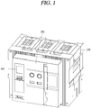
- a circuit breaker for example, an air circuit breaker, on which a magnetic trip device for a circuit breaker according to a preferred embodiment of the present disclosure is mountable (applicable), may be configured with reference to FIG. 1 .
- the air circuit breaker includes a main body 100 having a switching mechanism and an arc extinguishing mechanism, and a front panel part 200 having an operation and display unit, and an over current relay 300 as a controller of the air circuit breaker is provided at one side of the front panel part 200.
- FIG. 1 is an external perspective view illustrating only the external shapes of the constituent parts.
- a magnetic trip device 20 for a circuit breaker comprises an actuator coil part 21, an output plate 22, a micro switch 28, a switch driving lever mechanism 26, 27, a driving lever bias spring 32, an automatic reset mechanism 23, a driving lever latch 29, and an avoiding portion 22d, 22e.
- reference numeral 10 designates a switching mechanism of the circuit breaker, and the switching mechanism 10 may comprises a trip spring as an energy source for a trip operation (automatic circuit breaking operation), and a closing spring as an energy source for a closing operation (a so-called ON operation), a power transmission mechanism, a movable contact arm, a stationary contact arm, and the like.
- reference numeral 11 designates a main switching shaft commonly connected to a plurality of movable contact arms for each phase for a closing operation for simultaneously bringing a plurality of movable contact arms for each phase (pole) into contact with the corresponding stationary contact arm, and an opening operation for opening (tripping) the plurality of movable contact arms from the stationary contact arms.
- the actuator coil part 21 includes a coil (not shown) magnetized or demagnetized according to whether or not a magnetization control signal is received from the over current relay 300, and plunger 21a configured to move an advanced position or retracted position according to the magnetization or demagnetization of the coil.
- a buffer spring 21b may be additionally provided around an axis of the plunger 21a to buffer an impact when the plunger 21a collides with the output plate 22.
- the over current relay 300 outputs the magnetization control signal only when the circuit breaker is to be tripped.
- the output plate 22 serves as an output portion of the magnetic trip device 20 of the present disclosure, and referring to FIG. 2 , the output plate 22 presses a trip lever 10a of the switching mechanism 10 to trigger the switching mechanism 10 to perform a trip operation.
- the output plate 22 may be provided with a lever pressing portion 22a on one side as an operating portion for pressing the trip lever 10a.
- the lever pressing portion 22a is provided to protrude upward from the other plate surfaces of the output plate 22 so as to provide a space for an end portion of the trip lever 10a to be located immediately therebelow.
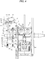
- a central portion of the output plate 22 is provided with a through hole (refer to FIG. 4 , reference number is not given) for allowing a pressing rod 23f as an upper end portion of a lower automatic reset mechanism 23 to pass therethrough.
- the triggered switching mechanism 10 discharges elastic energy charged in the trip spring as well known to separate the movable contact arm from the corresponding stationary contact arm by interlocking mechanical components included in the switching mechanism 10, thereby completing a trip operation for automatically breaking the circuit.
- the output plate 22 is rotatably provided on a movement path of the plunger 21a, and rotates in a first direction (clockwise direction in FIG. 3 ) by the pressing of the plunger 21a.
- An output plate rotating shaft 22b may be provided to rotatably support the output plate 22, and both end portions of the output plate rotating shaft 22b can be supported by both side plates of an enclosure of the magnetic trip device 20.
- the magnetic trip device 20 further comprises a return spring 22c for applying an elastic force to return the output plate 22 to an initial position.
- the output plate 22 returns to the initial position while rotating in a second direction (counter-clockwise in FIG. 3 ) due to a resilient force imposed by the return spring 22c.
- an elastic modulus of the return spring 22c may be configured to be greater than that (elastic modulus) of the driving lever bias spring 32.
- the micro switch 28 is a means for outputting an electrical signal or not according to whether or not a mechanical pressure is received, and has an operation lever portion (refer to 28a in FIG.
- the switch driving lever mechanism 26, 27 is a means (unit) rotatable to a first position for pressing the operation lever portion 28a and a second position for releasing the operation lever portion 28a so as to open or close the micro switch 26.
- the switch driving lever mechanism 26, 27 may include a switch driving lever 26 and an arm 27.
- the switch driving lever 26 is provided as a means (unit) capable of rotating the arm 27.
- the switch driving lever 26 includes a rotating shaft portion 26a, a first lever portion 26e, an arm contact surface portion 26b, and a third lever portion 26c.
- the rotating shaft portion 26a is a portion that provides a rotational center axis to allow the switch driving lever 26 to rotate.
- the first lever portion 26e extends from the rotating shaft portion 26a toward the output plate 22 (extends downward in the drawing), and contacts with an upper surface of the output plate 22 to be pressed by the output plate 22. Furthermore, the first lever portion 26e is rotatable along the output plate 22.
- the third lever portion 26c as an upper portion of the switch driving lever 26 receives an elastic force from the driving lever bias spring 32 to rotate in a clockwise direction in FIG. 3 .
- the output plate 22 is separated from the first lever portion 26e to eliminate a pressure that has been pressed while rotating in a clockwise direction due to the pressing of the plunger 21a, the first lever portion 26e rotates in a clockwise direction due to an elastic force imposed from the driving lever bias spring 32.
- the arm contact surface portion 26b is a portion that brings into contact with the arm 27 of the switch driving lever 26 to transmit a driving force to the arm 27 such that the arm 27 rotates to the first position or the second position.
- the arm contact surface portion 26b is located at a longitudinal center portion of the switch driving lever 26, and extends in a horizontal direction from the rotating shaft portion 26a to be located below a power receiving end portion 27a of the arm 27.
- a reinforcing thick portion 26d for reinforcing a strength of a third lever portion 26c and the arm the contact surface portion 26b which will be described later may be provided between the arm contact surface portion 26b and the third lever portion 26c.
- the reinforcing thick portion 26d may be formed to have a substantially triangular side shape as illustrated in FIG. 3 .
- the third lever portion 26c is a portion of the switch driving lever 26 that extends upward from the rotating shaft portion 26a to be restrained (locked) or released by the driving lever latch 29.
- a front end portion of the third lever portion 26c, which faces the driving lever latch 29, is formed to have an inclined surface or a curved surface so as to allow a hook portion 29b of the driving lever latch 29 which will be described later to ride over easily while being in contact therewith.
- a rear surface of the third lever portion 26c is formed with a flat surface, and thus the third lever portion 26c is configured not to be easily released from the hook portion 29b of the driving lever latch 29 after the hook portion 29b rides over the front end portion of the third lever portion 26c.
- a spring supporting seat portion may be provided as a protruding portion inserted into the driving lever bias spring 32 on a rear surface of the third lever portion 26c to support one end portion of the driving lever bias spring 32.
- the arm 27 extends toward the operation lever portion 28a of the micro switch 28 to rotate to a first portion for pressing the operation lever portion 28a of the micro switch 28 and a second position for releasing the operation lever portion 28a.
- one end portion of the arm 27 may be supported by a hinge and a hinge supporting bracket provided at one side of an upper surface of the actuator coil part 21.
- the switch driving lever mechanism may be configured with only the switch driving lever 26.
- Such another embodiment is characterized in that the switch driving lever 26 includes a component portion that performs a function of the arm 27.
- the switch driving lever 26 may include a rotating shaft portion 26a, a first lever portion 26e, a second lever portion, and a third lever portion 26c.
- the first lever portion 26e extends from the rotating shaft portion 26a toward the output plate 22 to be rotatable along the output plate 22.
- the second lever portion is a portion of the switch lever 26 that performs a function of the arm 27, and can be provided by forming the arm contact surface portion 26b of the embodiment to extend toward the operation lever portion 28a of the micro switch 28.
- the second lever portion is a portion of the switch driving lever 26 that extends from the rotating shaft portion 26a toward the operation lever portion 28a of the micro switch 28 to be rotatable to a first position for pressing the operation lever portion 28a and a second position for releasing the operation lever portion 28a.
- the third lever portion 26c extends upward from the rotating shaft portion 26a to be restrained (locked) or released by the driving lever latch 29.
- the driving lever bias spring 32 included in the magnetic trip device 20 is provided at a predetermined position to elastically press the switch driving lever mechanism to rotate to the second position.
- the driving lever bias spring 32 may be configured with a compression spring according to a preferred embodiment, and an end portion of the driving lever bias spring 32 can be supported by the spring supporting seat portion provided on a rear surface of the third lever portion 26c, and the other end thereof can be supported by a spring support member (reference number is not given) provided to face the third lever portion 26c and is fixed.
- the automatic reset mechanism 23 included in the magnetic trip device 20 is a means (unit) that drives the plunger 21a of the actuator coil part 21 to the retracted position in interlocking with the main switching shaft 11 of the circuit breaker subsequent to a trip operation.
- the automatic reset mechanism 23 comprises a rotation shaft 23a, a rotating plate 23b, a cylinder 23c, a bushing 23d, a pressing rod 23f, a driving lever 11a, and a power receiving portion 23i.
- the automatic reset mechanism 23 may further comprise a first buffer spring 23e, a return spring 24, and a spring support member 25.
- the automatic reset mechanism 23 may further comprise a lower rod 23g and a second buffer spring 23h.
- the rotation shaft 23a is fixedly provided to support the rotating plate 23b so as to be rotatable.
- the rotation shaft 23a can be configured with a pair of protruding shaft portions formed to protrude from a wall surface of the enclosure (not shown) of the magnetic trip device 20 according to the present disclosure.
- the rotating plate 23b is rotatable around the rotation shaft 23a, and provided at a position facing the driving lever 11a to be brought into contact with the driving lever 11a coupled to the rotating plate 23b to rotate together with the main switching shaft 11 at a side of the main switching shaft 11 of the circuit breaker.
- the rotating plate 23b may be made of a metallic plate having a substantially U-shape, and includes both leg portions supported by the rotation shaft 23a, a spring seat portion 23b1 provided between the both leg portions as a portion for supporting one end portion of the first buffer spring 23e and a pair of leg portions 23a, and a power receiving portion 23i extended to be contactable with the driving lever 11a as illustrated in FIG. 3 or 5 .
- the spring seat portion 23b1 of the rotating plate 23b is provided with a through hole (not shown) for allowing the cylinder 23c to pass therethrough in a vertical direction.
- a lower portion of the cylinder 23c may be placed through the through hole of the rotating plate 23b, and a coupling pin (not shown) may be connected to an upper portion of the cylinder 23c, and the cylinder 23c can be coupled to the bushing 23d by inserting the coupling pin into a long hole (not shown) provided vertically on the bushing 23d.
- a long hole (not shown) in a vertical direction may be also provided at a lower portion of the cylinder 23c, and the cylinder 23c can be coupled to the lower rod 23g by inserting a coupling pin (not shown) connected to the lower rod 23g into the long hole.
- the bushing 23d is integrally (in a single body) coupled to the pressing rod 23f to be movable up and down together.
- a diameter of the bushing 23d is larger than that of the cylinder 23c and that of the first buffer spring 23e to support the other end of the first buffer spring 23e not to be detached therefrom.
- the bushing 23d may be provided with a vertical long hole and coupled to the cylinder 23c by the coupling pin.
- the function of the bushing 23d is to support the other end of the first buffer spring 23e not to be detached therefrom as described above, and at the same time, to connect the pressing rod 23f and the cylinder 23c in the middle.
- the pressing rod 23f as an output portion of the automatic reset mechanism 23 is capable of directly contacting and pressing the plunger 21a of the actuator coil part 21, and is installed in an upright posture in a vertical direction.
- the pressing rod 23f can be coupled to the bushing 23d in various methods such as welding, screw coupling, connection pin coupling, and the like.
- a driving lever 11a which is rotatable in the same direction along with the main switching shaft 11 is provided at a position facing the automatic reset mechanism 23 of the main switching shaft 11 to interlock the main switching shaft 11 with the automatic reset mechanism 23.
- the driving lever 11a has a cam surface portion 11a1 whose radius of curvature changes in order to interlock the automatic reset mechanism 23 to operate.
- the cam surface portion 11a1 may be formed on at least a part of an outer circumferential surface of the driving lever 11a.
- the power receiving portion 23i is in a state of being separated from the driving lever 11a of the main switching shaft 11.
- the rotating plate 23b also rotates in a counter-clockwise direction by the counter-clockwise rotation of the power receiving portion 23i.
- the bushing 23d connected to the rotating plate 23b via the first buffer spring 23e, the pressing rod 23f and the cylinder 23c coupled to the bushing 23d, the lower rod 23g connected to the cylinder 23c by the coupling pin, and the second buffer spring 23h provided around the lower rod 23g move upward.
- a spring support (not shown) for hanging and supporting one end portion of the return spring 24 may be provided at one side of the power receiving portion 23i, and through hole portions (not shown) may be provided at a left and a right side of the relevant spring support to allow one end portion (hook type end portion) of the return spring 24 to pass therethrough.
- the first buffer spring 23e can be configured with a compression spring and provided between the bushing 23d and the spring seat portion 23b1 of the rotating plate 23b.
- the return spring 24 can be configured with a tension spring whose one end is supported by the power receiving portion 23i and the other end is supported by the spring support member 25.
- the return spring 24 When the main switching shaft 11 is at a trip position, the return spring 24 is extended by pulling of the rotating plate 23b and the power receiving portion 23i that rotate in a counter-clockwise direction to charge elastic energy as illustrated in FIG. 7 . And when the main switching shaft 11 is at a closing position of the circuit breaker, the return spring 24 discharges the charged elastic energy to rotate the rotating plate 23b and the power receiving portion 23i in a clockwise direction as illustrated in FIG 3 .
- the spring support member 25 is fixed in position and may support the other end portion of the return spring 24.
- the spring support member 25 may be integrally formed with the enclosure of the magnetic trip device 20 according to the present disclosure (preferably, the enclosure formed by molding a synthetic resin material having electrical insulation properties) or configured with a separate body from the enclosure and fixed to the enclosure by a fixing means such as a screw.
- the spring support member 25 may have a hook supporting portion and a hook receiving groove portion to hang and support the other end of the return spring 24.
- the lower rod 23g can be coupled to the cylinder 23c to move up or down together with the cylinder 23c according to the rotation of the rotating plate 23b.
- the second buffer spring 23h is configured with a compression spring according to a preferred embodiment and provided around the lower rod 23g.
- a flange portion larger than a diameter of the second buffer spring 23h is provided at a lower end portion of the lower rod 23g to prevent the second buffer springs 23h from detaching downward.
- the second buffer spring 23h absorbs an impact from a lower side applied to the lower rod 23g.
- the driving lever latch 29 can rotate to a restraining position for preventing the switch driving lever 26 of the switch driving lever mechanism 26, 27 from rotating to the first position so as to maintain a trip indication state of the micro switch 28 subsequent to a trip operation. Or the driving lever latch 29 can rotate to a releasing position for allowing the rotation of the switch driving lever 26 to rotate to the first position.
- the driving lever latch 29 is provided adjacent to the switch driving lever mechanism.
- the driving lever latch 29 comprises a rotating shaft portion 29a, a hook portion 29b and a release drive force receiving portion 29c.
- the rotating shaft portion 29a is a portion that provides a central axis portion to allow the switch driving lever 29 to rotate.
- the rotating shaft portion 29a may be formed integrally with the driving lever latch 29 such that both end portions of the rotating shaft portion 29a are inserted into and supported by a pair of shaft support groove portions provided on a side wall of the enclosure of the magnetic trip device 20 or may be configured separately from the driving lever latch 29 such that the both end portions are inserted into and supported by the shaft support groove portions.
- the hook portion 29b is extended toward the switch driving lever 26 of the switch driving lever mechanisms 26, 27 from the rotating shaft portion 29a to restrain (lock) the switch driving lever 26 of the switch driving lever mechanisms 26, 27.
- the hook portion 29b is rotatable around the rotating shaft portion 29a to a position for locking the third lever portion 26c of the switch driving lever 26 and a position for releasing the third lever portion 26c.
- the position (state) of locking the third lever portion 26c of the switch driving lever 26 can be voluntarily implemented by the third lever portion 26c when the third lever portion 26c rotates in a clockwise direction in the drawing by the elastic pressing of the driving lever bias spring 32 in a state of alarming that the circuit breaker is in a trip state.
- the hook portion 29b rides over a front end portion of the third lever portion 26c formed on a inclined surface or a curved surface to restrain (lock) the third lever portion 26c.
- the manual reset lever 31 includes a pressing protrusion portion 31a that presses the driving lever latch 29 in order to drive the driving lever latch 29 to the release position.
- the release drive force receiving portion 29c is extended from the rotating shaft portion 29a to an opposite side of the hook portion 29b and contacts with the manual reset lever 31.
- a surface facing the pressing protrusion portion 31a is configured with an inclined surface 29c1 according to a preferred embodiment.
- a surface of the release driving force receiving portion 29c facing the pressing protrusion portion 31a may be configured with the inclined surface 29c1, thereby obtaining an effect capable of effectively transforming a pressing force exerted from the manual reset lever 31 into a rotational force of the driving lever latch 31.
- the magnetic trip device 20 further comprises a bias spring 30 which applies an elastic force to the driving lever latch 31 in one direction.
- one direction is a counter-clockwise direction in the drawing as a direction of rotation of the hook portion 29b of the driving lever latch 29 to a position where the third lever portion 26c of the switch driving lever 26 is restrained.
- the bias spring 30 is configured with a torsion spring.
- the avoiding portions 22d, 22e are formed on the output plate 22 to avoid contacting with the switch driving lever mechanisms 26, 27 for a mutual independent operation between the switch driving lever mechanisms 26, 27 and the output plate 22.
- the avoiding portion can be configured with a concave groove portion 22d formed concavely from an upper surface of the output plate 22 to a lower portion thereof as illustrated in FIGS 5 and 7 on the output plate 22 for the switch driving lever mechanism to avoid the output plate without being interfered with the output plate rotating to an initial position.
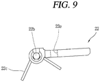
- the avoiding portion can be configured with a through hole portion 22e formed to pass through the output plate 22 as illustrated in FIG. 9 for the switch driving lever mechanisms 26, 27 to avoid the output plate 22 without being interfered with the output plate 22.
- the magnetic trip device 20 further comprises a manual reset lever 31 as illustrated in FIGS. 3 , 5 , 7 through 9 .
- the manual reset lever 31 is provided at a position capable of pressing the driving lever latch 29 to press the driving lever latch 29 to rotate to the release position while being moved by a manual operation force.
- the manual reset lever 31 is configured with a substantially elongated rod-shaped member, and most of the length thereof is located inside the magnetic trip device 20, but a part thereof may be exposed to the outside through the front plate portion 200 of the circuit breaker. A marking may be provided at a portion of the front plate portion 200 where the manual reset lever 31 is exposed to inform the user that reset of the driving lever latch 29 can be achieved by pressing the exposed portion of the manual reset lever 31.
- the magnetic trip device 20 may further comprise a pair of guide members 34 formed in a protruding manner on an inner wall surface of the enclosure of the magnetic trip device 20 and formed in a predetermined length to be higher and lower than the manual reset lever 31 so as to guide the manual reset lever 31 to horizontally move due to a manual operation force as illustrated in FIG. 8 .
- the manual reset lever 31 has a pressing protrusion portion 31a for pressing the release driving force receiving portion 29c of the driving lever latch 29 to rotate the driving lever latch 29 to the release position.
- the magnetic trip device 20 further comprises a lever return spring 33 for returning the manual reset lever 31 to its original position (a position that the exposed portion of the manual reset lever 31 is protruded from the front plate portion 200 outwardly) when there is no external force (for instance, a force pressed by a user's hand) pressing the manual reset lever 31.
- the lever return spring 33 can be configured with a tension spring, one end of the lever return spring 33 may be connected to the manual reset lever 31 and the other end of the lever return spring 33 may be fixed to a rear surface of the front plate portion 200 directly or through another member.
- the operation into an alarm indicating state is first carried out before the circuit breaker operates from a closing state to a trip state.
- the over current relay 300 of FIG. 1 senses the occurrence of a fault current such as an over current or a short-circuit current on a circuit to output a trip control signal for breaking the circuit to the magnetic trip device 20 according to a preferred embodiment of the present disclosure.
- the trip control signal is transmitted to the actuator coil part 21 of the magnetic trip device 20 through an unillustrated signal line which is wired as a signal transmission path between the over current relay 300 and the magnetic trip device 20 to magnetize the coil (not shown) of the actuator coil part 21.
- the plunger 21a presses the lower output plate 22 while advancing according to the magnetization of the coil.
- the lower output plate 22 overcomes an elastic force of the return spring 22c from a substantially horizontal state as illustrated in FIGS. 2 and 3 and rotates in a clockwise direction as illustrated in FIGS. 4 and 5 to become a state in which one side thereof is inclined downward.
- the lever pressing portion 22a presses the trip lever 10a located just below. Therefore, the switching mechanism 10 operates to a trip position due to the displacement of the trip lever 10a.
- the output plate 22 is rotated in a clockwise direction as illustrated in FIGS. 4 and 5 to release the first lever portion 26e of the switch driving lever 26.
- the driving lever bias spring 32 which elastically biases the third lever portion 26c of the switch driving lever 26 to rotate in a clockwise direction in the drawing is extended while pushing the third lever portion 26c, and thus the switch driving lever 26 is rotated in a clockwise direction as illustrated in FIG. 5 .
- the third lever portion 26c of the switch driving lever 26 is restrained (locked) by the driving lever latch 29 in a state of rotating in a clockwise direction.
- the arm contact surface portion 26b of the switch driving lever 26 is also disengaged from the power receiving end portion 27a of the arm 27 while also rotating in a clockwise direction, and as a result, the arm 27 is rotated from a position illustrated in FIG. 2 to a position illustrated in FIG. 4 in a counter-clockwise direction by its own weight. Therefore, the operation lever portion 28a of the micro switch 28 which has been pressed by the arm 27 in FIG. 2 is released.
- a circuit from an electric power source to an output terminal of the micro switch 28 may be connected while an internal contact interlocked with the operation lever portion 28a is closed to output an electric signal of a predetermined voltage indicating that the circuit breaker is in a trip operation state from the micro switch 28.
- the electric signal of the predetermined voltage may operate an outside of the circuit breaker, that is, for instance, an alarm lamp, a buzzer, and the like of a front display and operation panel of a switchgear accommodating the circuit breaker, thereby alarming that the circuit breaker is in a trip operation state in which a fault current is currently broken.
- a trip indicating state can be maintained after the trip operation, thereby preventing the occurrence of an electrical safety accident that may occur by operating the circuit breaker to a closed position (i.e., an ON position).
- the main switching shaft 11 rotates in a counter-clockwise direction from a state illustrated in FIG. 3 to a state illustrated in FIG. 7 .
- the driving lever 11a coupled to the main switching shaft 11 to rotate together also rotates in a counter-clockwise direction.
- the rotating plate 23b also rotates in a counter-clockwise direction due to a counter-clockwise rotation of the power receiving portion 23i, and as a result, the bushing 23d connected to the rotating plate 23b via the first buffer spring 23e, the pressing rod 23f and the cylinder 23c coupled to the bushing 23d, the lower rod 23g connected to the cylinder 23c by the coupling pin, and the second buffer spring 23h provided around the lower rod 23g move upward.
- the third lever portion 26c of the switch driving lever 26 maintains a state of being restrained by the driving lever latch 29 to allow the micro switch 28 to maintain a trip indicating state subsequent to a trip operation, thereby preventing the occurrence of an electrical safety accident that may occur by operating the circuit breaker to a closed position (i.e., an ON position) in a state where the cause of the trip is not removed.
- the circuit breaker can be operated again to a closing state (an ON state), and maintaining the alarm indicating of the switch driving lever 26 by the driving lever latch 29 to alarm that it is in a trip sate is no longer necessary.
- the driving lever latch 29 rotates in a clockwise direction around the rotating shaft portion 29a, and accordingly, the hook portion 29b is disengaged (detached) from the third lever portion 26c of the switch driving lever 26.
- the first lever portion 26e which is a lower portion of the switch driving lever 26, is pressed upward by the output plate 22 in the state as illustrated in FIGS. 6 and 7 , and is rotated in a counter-clockwise direction around the rotating shaft portion 26a to become the state as illustrated in FIG. 3 .
- the arm contact surface portion 26b of the switch driving lever 26 rotating in a counter-clockwise direction presses the arm 27 while moving upward, and as a result, the arm 27 rotates in a clockwise direction to press the operation lever portion 28a of the micro switch 28.
- the circuit from the electric power source to the output terminal of the micro switch 28 is broken while an internal contact interlocking with the operation lever portion 28a is open, the electric signal of the predetermined voltage indicating that the circuit breaker is in a trip operation state is not outputted from the micro switch 28.
- the driving lever bias spring 32 returns to a compressed state in which elastic energy is charged as illustrated in FIG. 3 by a counter-clockwise rotation of the switch driving lever 26.
- a magnetic trip device of a circuit breaker includes the driving lever latch so as to lock the micro switch to maintain a trip indicating state subsequent to a trip operation, and includes the automatic reset mechanism so as to automatically initialize the plunger of the actuator coil part to a retracted position which is an initial position in interlocking with the main switching shaft, and include the avoiding portion so as to independently perform a trip operation without being affected by an initial position returning operation of the output plate due to the return spring of the output plate and then restrain the micro switch to maintain the trip indicating state.
- a magnetic trip device of a circuit breaker according to the present disclosure further comprises a manual reset lever, and thus the driving lever latch can be forcibly rotated to the release position by manually operating the manual reset lever after removing the cause of a fault, thereby having an effect capable of operating the magnetic trip device to stop a trip indicating state.
- the driving lever latch comprises a rotating shaft portion, a hook portion and a release driving force receiving portion brought into contact with the manual reset lever, and the manual reset lever is provided with a pressing protrusion portion, and thus the driving lever latch can be rotatable around the rotating shaft portion, and restrain the switch driving lever mechanism by the hook portion, and receive a driving force transmitted from the pressing protrusion portion of the manual reset lever to the release driving force receiving portion, thereby having an effect capable of allowing the driving lever latch to rotate to a release position.
- a surface facing the pressing protrusion portion is configured with an inclined surface, thereby having an advantage capable of effectively transforming a pressing force from the manual reset lever into a rotational force of the driving lever latch.
- the automatic reset mechanism comprises the rotating shaft, the rotating plate, the cylinder, the bushing, the pressing rod, the driving lever having the cam surface portion and the power receiving portion, and thus the power receiving portion and the rotating plate can rotate together due to bringing into contact with the cam surface portion of the driving lever when the driving lever rotating together with the main switching shaft of the circuit breaker is moved to a trip position, and the rotation of the rotating plate may cause the cylinder, the bushing and the pressing rod to rise, thereby having an effect capable of allowing the pressing rod to press the plunger of the actuator coil part so as to automatically initialize the position to a retracted position.
- the automatic reset mechanism further comprises a first buffer spring thereby buffering an impact when the pressing rod moving upward pushes up the plunger to a retracted position, and further comprises a return spring connected to the rotating plate thereby being extended when the main switching shaft is in a trip position so as to charge elastic energy, and the charged elastic energy can be discharged when the main switching shaft is in a closing position, thereby having an effect capable of rotating the rotating plate and the power receiving portion in a first direction to return to an initial position.
- the switch driving lever mechanism comprises the arm and the switch driving lever, and the switch driving lever comprises the rotating shaft portion, the first lever portion, the arm coupling portion and the third lever portion, thereby having an effect capable of switching the micro switch through the arm contact surface portion and the arm, rotating the first lever portion around the rotating shaft portion according to the output plate, and restraining or releasing the switch driving lever via the third lever portion due to the driving lever latch.
- the avoiding portion is configured with an avoiding groove portion formed concavely on the output plate, and thus the switch driving lever mechanism can be avoided from the output plate rotating to an initial position without being interfered therewith, thereby having an effect capable of maintaining the switch driving lever mechanism in a trip indicating state regardless of a returning operation of the output plate.
- the avoiding portion is configured with a through hole portion formed to pass through the output plate, and thus the switch driving lever mechanism may be avoided from the output plate without being interfered therewith, thereby having an effect capable of maintaining the switch driving lever mechanism in a trip indicating state regardless of a returning operation of the output plate.
Claims (7)
- Dispositif de déclenchement magnétique pour un disjoncteur, comprenant :une partie de bobine d'actionneur (21) qui possède un piston (21a) conçu pour se déplacer jusqu'à une position avancée ou une position rétractée selon la magnétisation ou la démagnétisation d'une bobine ;une plaque de sortie (22) qui est prévue de manière rotative sur un trajet de déplacement du piston (21a) pour tourner dans un premier sens par la pression du piston (21a) ;un micro-commutateur (28) qui possède une portion de levier d'actionnement (28a) en saillie vers l'extérieur et est conçu pour délivrer en sortie un signal électrique indiquant un état du disjoncteur selon qu'une pression est exercée ou non sur la portion de levier d'actionnement (28a) ;un mécanisme de levier d'entraînement de commutateur (26, 27) qui est conçu pour tourner jusqu'à une première position pour exercer une pression sur la portion de levier d'actionnement (28a) et une seconde position pour libérer la portion de levier d'actionnement (28a) de façon à ouvrir le micro-commutateur (28) ;un ressort de sollicitation de levier d'entraînement (32) qui est prévu à une position prédéterminée pour exercer une pression élastique sur le mécanisme de levier d'entraînement de commutateur (26, 27) afin de le faire tourner jusqu'à la seconde position ;un mécanisme de réinitialisation automatique (23) qui est conçu pour exercer une pression sur le piston (21a) de la partie de bobine d'actionneur (21) jusqu'à la position rétractée en verrouillage avec un arbre de commutation principal (11) du disjoncteur consécutivement à une opération de déclenchement ;un loquet de levier d'entraînement (29) qui est conçu pour tourner jusqu'à une position de limitation destinée à empêcher le mécanisme de levier d'entraînement de commutateur (26, 27) de tourner jusqu'à la première position, même lorsque le piston (21a) est déplacé jusqu'à la position rétractée par le mécanisme de réinitialisation automatique (23) de façon à permettre au micro-commutateur (28) de conserver un état d'indication de déclenchement consécutivement à une opération de déclenchement, et une position de libération destinée à permettre au mécanisme de levier d'entraînement de commutateur (26, 27) de tourner jusqu'à la première position, et prévu à côté du mécanisme de levier d'entraînement de commutateur (26, 27) ;une portion d'évitement (22d, 22e) qui est formée sur la plaque de sortie (22) pour éviter une mise en contact avec le mécanisme de levier d'entraînement de commutateur (26, 27) pour un fonctionnement mutuellement indépendant entre le mécanisme de levier d'entraînement de commutateur (26, 27) et la plaque de sortie (22), etun levier de réinitialisation manuelle (31) qui est prévu à une position capable d'exercer une pression sur le mécanisme de levier d'entraînement de commutateur (26, 27) et le loquet de levier d'entraînement (29) afin d'exercer une pression sur le mécanisme de levier d'entraînement de commutateur (26, 27) devant se situer à une première position, et d'exercer une pression sur le loquet de levier d'entraînement (29) afin de le faire tourner jusqu'à la position de libération tout en étant déplacé par une force de fonctionnement manuelle,dans lequel le loquet de levier d'entraînement (29) comprend :une portion d'arbre rotatif (29a) ;une portion de crochet (29b) qui est étendue depuis la portion d'arbre rotatif (29a) vers le mécanisme de levier d'entraînement de commutateur (26, 27) pour limiter le mécanisme de levier d'entraînement de commutateur (26, 27) ; etune portion de réception de force d'entraînement de libération (29c) qui est étendue depuis la portion d'arbre rotatif (29a) vers un côté opposé de la portion de crochet (29b) pour être en contact avec le levier de réinitialisation manuelle (31),dans lequel le levier de réinitialisation manuelle (31) comprend une portion de saillie de pression (31a) qui est conçue pour exercer une pression sur la portion de réception de force d'entraînement de libération (29c) afin de faire tourner le loquet de levier d'entraînement (29) jusqu'à la position de libération.
- Dispositif de déclenchement magnétique selon la revendication 1, dans lequel la portion de réception de force d'entraînement de libération (29c) est conçue de sorte qu'une surface tournée vers la portion de saillie de pression (31a) soit une surface inclinée (29c1).
- Dispositif de déclenchement magnétique selon la revendication 1, dans lequel le mécanisme de réinitialisation automatique (23) comprend :un arbre rotatif (23a) ;une plaque rotative (23b) qui est supportée en rotation par l'arbre rotatif (23a) ;un cylindre (23c) qui possède une portion inférieure située pour passer à travers un trou traversant de la plaque rotative (23b) ;une rondelle (23d) qui est munie d'un long trou vertical pour être couplée au cylindre (23c) par une goupille de couplage insérée dans le long trou ;une tige de pression (23f) qui est couplée à la rondelle (23d) pour exercer une pression en contact direct avec le piston (21a) de la partie de bobine d'actionneur (21) en tant que portion de sortie du mécanisme de réinitialisation automatique (23) ;un levier d'entraînement (11a) qui est couplé à l'arbre de commutation principal (11) du disjoncteur pour qu'ils puissent tourner ensemble, le levier d'entraînement (11a) ayant une portion de surface de came (11a1) ; etune portion de réception d'énergie (23i) qui est prévue pour s'étendre depuis la plaque rotative (23b) vers le levier d'entraînement (11a) afin de mettre en contact la portion de surface de came (11a1) du levier d'entraînement (11a) pour recevoir de l'énergie pendant une opération de déclenchement.
- Dispositif de déclenchement magnétique selon la revendication 3, dans lequel le mécanisme de réinitialisation automatique (23) comprend en outre :un premier ressort d'amortissement (23e) qui est prévu entre la rondelle (23d) et la plaque rotative (23b) pour amortir un impact lorsque la tige de pression (23f) pousse vers le haut le piston (21a) jusqu'à la position rétractée ; etun ressort de rappel (24) qui est raccordé à la plaque rotative (23b), et mis sous tension lorsque l'arbre de commutation principal (11) se trouve dans une position de déclenchement pour charger de l'énergie élastique, et lorsque l'arbre de commutation principal (11) se trouve dans une position de fermeture pour faire tourner la plaque rotative (23b) et la portion de réception d'énergie (23i) dans un premier sens par décharge de l'énergie élastique chargée.
- Dispositif de déclenchement magnétique selon la revendication 1, dans lequel le mécanisme de levier d'entraînement de commutateur (26, 27) comprend :un bras (27) qui s'étend vers la portion de levier d'actionnement (28a) du micro-commutateur (28) et capable de tourner jusqu'à une première position destinée à exercer une pression sur la portion de levier d'actionnement (28a) du micro-commutateur (28) et une seconde position destinée à libérer la portion de levier d'actionnement (28a) ; etun levier d'entraînement de commutateur (26) qui est capable de faire tourner le bras (27),dans lequel le levier d'entraînement de commutateur (26) comprend :une portion d'arbre rotatif (26a) ;une première portion de levier (26e) qui s'étend depuis la portion d'arbre rotatif (26a) vers la plaque de sortie (22) pour tourner le long de la plaque de sortie (22) ;une portion de surface de contact de bras (26b) qui est contact avec le bras (27) pour transmettre une force d'entraînement au bras (27) de façon à faire tourner le bras (27) jusqu'à la première position et la seconde position ; etune troisième portion de levier (26c) qui s'étend vers le haut depuis la portion d'arbre rotatif (26a).
- Dispositif de déclenchement magnétique selon la revendication 1, dans lequel la portion d'évitement (22d, 22e) est formée sur la plaque de sortie (22), et conçue avec une portion de rainure concave (22d) formée en une forme concave pour empêcher le mécanisme de levier d'entraînement de commutateur (26, 27) de subir l'interférence de la plaque de sortie (22) en rotation jusqu'à une position initiale.
- Dispositif de déclenchement magnétique selon la revendication 1, dans lequel la portion d'évitement (22d, 22e) est conçue avec une portion de trou traversant (22e) formée pour passer à travers la plaque de sortie (22) de sorte que le mécanisme de levier de commutation (26, 27) est évité sans subir l'interférence de la plaque de sortie (22).
Applications Claiming Priority (1)
| Application Number | Priority Date | Filing Date | Title |
|---|---|---|---|
| KR1020170032645A KR102299858B1 (ko) | 2017-03-15 | 2017-03-15 | 회로차단기의 전자 트립 장치 |
Publications (2)
| Publication Number | Publication Date |
|---|---|
| EP3376521A1 EP3376521A1 (fr) | 2018-09-19 |
| EP3376521B1 true EP3376521B1 (fr) | 2020-01-29 |
Family
ID=60629589
Family Applications (1)
| Application Number | Title | Priority Date | Filing Date |
|---|---|---|---|
| EP17206203.6A Active EP3376521B1 (fr) | 2017-03-15 | 2017-12-08 | Dispositif de déclenchement magnétique de disjoncteur |
Country Status (5)
| Country | Link |
|---|---|
| US (1) | US10522314B2 (fr) |
| EP (1) | EP3376521B1 (fr) |
| KR (1) | KR102299858B1 (fr) |
| CN (1) | CN108630503B (fr) |
| ES (1) | ES2784431T3 (fr) |
Families Citing this family (2)
| Publication number | Priority date | Publication date | Assignee | Title |
|---|---|---|---|---|
| CN109712832B (zh) * | 2019-03-06 | 2023-11-03 | 鼎圣集团有限公司 | 一种防误操作系统及插接箱 |
| CN113871270A (zh) * | 2021-11-03 | 2021-12-31 | 慧泽电气有限公司 | 一种户内断路器弹簧操作机构 |
Family Cites Families (175)
| Publication number | Priority date | Publication date | Assignee | Title |
|---|---|---|---|---|
| US1834550A (en) * | 1928-11-15 | 1931-12-01 | Lyman C Reed | Circuit-breaker |
| US1976934A (en) * | 1932-10-11 | 1934-10-16 | Ite Circuit Breaker Ltd | Circuit controlling device |
| US2723326A (en) * | 1954-09-22 | 1955-11-08 | Allis Chalmers Mfg Co | Multiphase trip indicator means with common reset |
| US3182151A (en) * | 1962-03-28 | 1965-05-04 | Airpax Electronics | Remote indicating circuit breakers |
| GB1082897A (en) * | 1964-08-31 | 1967-09-13 | Teizo Fujita | An electromagnetic switch device |
| US3443258A (en) * | 1966-11-10 | 1969-05-06 | Square D Co | Circuit breaker with trip indicator |
| US3401363A (en) * | 1966-11-10 | 1968-09-10 | Square D Co | Multipole circuit breaker with trip indicator |
| US3622923A (en) * | 1968-07-11 | 1971-11-23 | Ite Imperial Corp | Electromagnetic device for circuit breaker trip assembly unit |
| US3683350A (en) * | 1969-11-06 | 1972-08-08 | Square D Co | Electrical circuit breaker with illuminated trip indicator |
| US3596218A (en) * | 1969-11-14 | 1971-07-27 | Square D Co | Circuit breaker with trip indicator |
| US3596219A (en) * | 1969-11-25 | 1971-07-27 | Square D Co | Circuit breaker with trip indicator |
| US3742402A (en) * | 1970-10-01 | 1973-06-26 | Heinemann Electric Co | Circuit breaker with on off and trip indication |
| US3973230A (en) * | 1974-04-25 | 1976-08-03 | General Electric Company | Circuit breaker accessories incorporating improved auxiliary switch |
| US3970975A (en) * | 1975-05-05 | 1976-07-20 | I-T-E Imperial Corporation | Ground fault circuit breaker with ground fault trip indicator |
| US4001739A (en) * | 1975-10-30 | 1977-01-04 | General Electric Company | Circuit breaker with bell alarm and breaker lockout accessory |
| US4037185A (en) * | 1976-03-11 | 1977-07-19 | General Electric Company | Ground fault circuit breaker with trip indication |
| JPS52116875A (en) * | 1976-03-26 | 1977-09-30 | Tokyo Kinzoku Kk | Circuit switch |
| US4042896A (en) * | 1976-04-01 | 1977-08-16 | General Electric Company | Manual and motor operated circuit breaker |
| US4056816A (en) * | 1976-10-05 | 1977-11-01 | Guim R | Light emitting diode blown circuit breaker indicator |
| US4121077A (en) * | 1977-06-29 | 1978-10-17 | Westinghouse Electric Corp. | Circuit breaker having improved movable contact position indicator |
| US4166989A (en) * | 1978-04-19 | 1979-09-04 | General Electric Company | Circuit breaker remote close and charged signalling apparatus |
| US4242551A (en) * | 1979-05-14 | 1980-12-30 | Carlingswitch, Inc. | Environmentally sealed rocker switch |
| US4250476A (en) * | 1979-11-13 | 1981-02-10 | S & C Electric Company | Auxiliary switch for indicating the condition of a circuit-interrupting device |
| US4308511A (en) * | 1980-01-10 | 1981-12-29 | Westinghouse Electric Corp. | Load management circuit breaker |
| DE3021867A1 (de) * | 1980-06-11 | 1981-12-17 | Brown, Boveri & Cie Ag, 6800 Mannheim | Selbstschalter |
| US4301433A (en) * | 1980-06-23 | 1981-11-17 | General Electric Company | Circuit breaker electrical closure control apparatus |
| US4301342A (en) * | 1980-06-23 | 1981-11-17 | General Electric Company | Circuit breaker condition indicator apparatus |
| US4347488A (en) * | 1980-11-21 | 1982-08-31 | Carlingswitch, Inc. | Multi-pole circuit breaker |
| US4382270A (en) * | 1981-04-07 | 1983-05-03 | Westinghouse Electric Corp. | Ground fault circuit breaker with mechanical indicator for ground fault trips |
| US4506246A (en) * | 1983-05-09 | 1985-03-19 | Square D Company | Interlock scheme for high amperage molded case circuit breaker |
| US4491709A (en) * | 1983-05-09 | 1985-01-01 | Square D Company | Motor and blade control for high amperage molded case circuit breakers |
| US4554524A (en) * | 1984-08-23 | 1985-11-19 | Westinghouse Electric Corp. | Secondary circuit breaker for distribution transformer with indicator light switch mechanism |
| US4652867A (en) * | 1984-09-25 | 1987-03-24 | Masot Oscar V | Circuit breaker indicator |
| US4768025A (en) * | 1984-09-25 | 1988-08-30 | Vila Masot Oscar | Circuit breaker indicator |
| US4760384A (en) * | 1984-09-25 | 1988-07-26 | Vila Masot Oscar | Light-emitting diode indicator circuit |
| US4623859A (en) * | 1985-08-13 | 1986-11-18 | Square D Company | Remote control circuit breaker |
| US4623861A (en) * | 1985-10-01 | 1986-11-18 | Carlingswitch, Inc. | Rocker actuator bracket assembly for a split case circuit breaker |
| US4801906A (en) * | 1987-10-19 | 1989-01-31 | General Electric Company | Molded case circuit breaker trip indicator unit |
| US5041805A (en) * | 1988-10-06 | 1991-08-20 | Mitsubishi Denki Kabushiki Kaisha | Remote-controlled circuit breaker |
| US4951021A (en) * | 1988-10-28 | 1990-08-21 | Eaton Corporation | Electromagnetic switching apparatus having dynamically balanced latch trip |
| US4900275A (en) * | 1989-05-18 | 1990-02-13 | Carlingswitch, Inc. | DIN rail mountable circuit breaker |
| US4968863A (en) * | 1989-06-29 | 1990-11-06 | Square D Company | Unitary breaker assembly for a circuit breaker |
| GB2246909B (en) * | 1990-07-16 | 1995-02-22 | Terasaki Denki Sangyo Kk | Circuit breaker including forced contact parting mechanism capable of self-retaining under short circuit condition |
| US5258732A (en) * | 1990-08-02 | 1993-11-02 | Furlas Electric Co. | Overload relay |
| US5089796A (en) * | 1990-09-19 | 1992-02-18 | Square D Company | Earth leakage trip indicator |
| US5095293A (en) * | 1990-11-30 | 1992-03-10 | Westinghouse Electric Corp. | Circuit breaker contact wipe indicator |
| US5113043A (en) * | 1991-02-25 | 1992-05-12 | General Electric Company | Circuit breaker safety interlock unit |
| US5140115A (en) * | 1991-02-25 | 1992-08-18 | General Electric Company | Circuit breaker contacts condition indicator |
| US5192941A (en) * | 1991-05-29 | 1993-03-09 | Westinghouse Electric Corp. | Overcurrent trip switch |
| US5223681A (en) * | 1991-10-18 | 1993-06-29 | Square D Company | Current limiting circuit breaker with over-molded magnet and metal plates |
| DE4233918B4 (de) * | 1992-10-08 | 2004-02-26 | Schulte-Elektrotechnik Gmbh & Co Kg | Elektrischer Schalter mit Stromüberwachung |
| EP0622821B1 (fr) * | 1993-04-28 | 1997-12-10 | Circuit Breaker Industries Limited | Boîtier pour disjoncteur |
| JP3141973B2 (ja) | 1993-09-27 | 2001-03-07 | 三菱電機株式会社 | 回路遮断器 |
| US5424701A (en) * | 1994-02-25 | 1995-06-13 | General Electric | Operating mechanism for high ampere-rated circuit breakers |
| US5453724A (en) * | 1994-05-27 | 1995-09-26 | General Electric | Flux shifter assembly for circuit breaker accessories |
| US5486660A (en) * | 1994-06-15 | 1996-01-23 | Carlingswitch, Inc. | Reset only rocker guard for split case circuit breaker |
| US5541800A (en) * | 1995-03-22 | 1996-07-30 | Hubbell Incorporated | Reverse wiring indicator for GFCI receptacles |
| US5657002A (en) * | 1995-12-27 | 1997-08-12 | Electrodynamics, Inc. | Resettable latching indicator |
| JP3246322B2 (ja) | 1996-03-29 | 2002-01-15 | 富士電機株式会社 | 回路遮断器の警報装置 |
| US5701110A (en) * | 1996-04-09 | 1997-12-23 | Square D Company | Circuit breaker accessory module |
| US5773778A (en) * | 1996-04-24 | 1998-06-30 | General Electric Company | Modular isolation block for circuit breaker contact arms |
| US5723832A (en) * | 1996-07-11 | 1998-03-03 | Hall; James K. | Switch guard for electric switch assembly |
| US5861784A (en) * | 1996-08-23 | 1999-01-19 | Square D Company | Manual override mechanism for a remote controlled circuit breaker |
| US5831500A (en) * | 1996-08-23 | 1998-11-03 | Square D Company | Trip flag guide for a circuit breaker |
| US5714940A (en) * | 1996-09-26 | 1998-02-03 | Eaton Corporation | Bell alarm for system power breaker |
| US5794759A (en) * | 1996-12-19 | 1998-08-18 | Mci Corporation | Protective cover for switches |
| US6130390A (en) * | 1997-06-19 | 2000-10-10 | General Electric Company | Contact position indicator for an industrial-rated circuit breaker |
| US5923261A (en) * | 1997-07-31 | 1999-07-13 | General Electric Company | Circuit breaker bell alarm accessory with automatic reset |
| US5920451A (en) * | 1997-09-05 | 1999-07-06 | Carlingswitch, Inc. | Earth leakage circuit breaker assembly |
| US5907140A (en) * | 1997-09-29 | 1999-05-25 | Eaton Corporation | Circuit breaker having a snap-in attachable collar |
| FR2774806B1 (fr) | 1998-02-09 | 2000-03-17 | Schneider Electric Ind Sa | Dispositif de declenchement pour un disjoncteur equipe d'une signalisation de defaut electrique |
| US6104265A (en) * | 1998-02-19 | 2000-08-15 | Eaton Corporation | Miniature circuit breaker with multipurpose auxiliary member |
| US5917391A (en) * | 1998-03-23 | 1999-06-29 | Pass & Seymour, Inc. | Transient voltage surge suppressor having a switch with overtravel protection |
| US5936535A (en) * | 1998-05-29 | 1999-08-10 | General Electric Company | Circuit breaker bell alarm accessory |
| US7098761B2 (en) * | 1998-08-24 | 2006-08-29 | Leviton Manufacturing Co., Inc. | Reset lockout mechanism and independent trip mechanism for center latch circuit interrupting device |
| US6107902A (en) * | 1998-11-19 | 2000-08-22 | General Electric Company | Circuit breaker with visible trip indicator |
| US6062914A (en) * | 1999-03-17 | 2000-05-16 | Carlingswitch, Inc. | Circuit breaker plug in bracket and auxiliary/alarm switch connector for use therewith |
| US6246304B1 (en) * | 1999-03-26 | 2001-06-12 | Airpax Corporation, Llc | Trip indicating circuit breaker |
| US6104266A (en) * | 1999-06-02 | 2000-08-15 | General Electric Company | Circuit breaker with trip indication arrangement |
| US6144271A (en) * | 1999-08-18 | 2000-11-07 | Eaton Corporation | Circuit breaker with easily installed removable trip unit |
| US6140897A (en) * | 1999-08-18 | 2000-10-31 | Eaton Corporation | Circuit breaker with externally lockable secondary cover latch |
| US6137385A (en) * | 1999-08-18 | 2000-10-24 | Eaton Corporation | Circuit breaker with side wall opening for a separate auxiliary device actuation lever |
| EP1098337A3 (fr) * | 1999-11-05 | 2002-08-07 | Siemens Energy & Automation, Inc. | Module accessoire de signalisation d'un disjoncteur à boítier moulé |
| JP2001160354A (ja) | 1999-12-02 | 2001-06-12 | Mitsubishi Electric Corp | 漏電警報機能付き配線用遮断器 |
| US6239677B1 (en) * | 2000-02-10 | 2001-05-29 | General Electric Company | Circuit breaker thermal magnetic trip unit |
| US7598828B1 (en) * | 2004-07-28 | 2009-10-06 | Pass & Seymour, Inc. | Protection device with a sandwiched cantilever breaker mechanism |
| US6528744B2 (en) * | 2000-06-16 | 2003-03-04 | Deere & Company | Cover for vehicle control switch |
| US6284991B1 (en) * | 2000-08-25 | 2001-09-04 | Carlingswitch, Inc. | Front mounting circuit breaker bracket assembly |
| US6710688B2 (en) * | 2001-04-30 | 2004-03-23 | Eaton Corporation | Circuit breaker |
| US6522228B2 (en) * | 2001-04-30 | 2003-02-18 | Eaton Corporation | Circuit breaker including an arc fault trip actuator having an indicator latch and a trip latch |
| US6542056B2 (en) * | 2001-04-30 | 2003-04-01 | Eaton Corporation | Circuit breaker having a movable and illuminable arc fault indicator |
| US6650515B2 (en) * | 2001-08-27 | 2003-11-18 | Eaton Corporation | Circuit breaker including power supply monitor circuit to disable a trip mechanism |
| US6897747B2 (en) * | 2002-05-10 | 2005-05-24 | Joseph T. Brandon | Circuit breaker |
| US6809282B2 (en) * | 2002-09-12 | 2004-10-26 | Carling Technologies, Inc. | D.C. circuit breaker with magnets for reducing contact arcing |
| US6954125B2 (en) * | 2002-10-09 | 2005-10-11 | Zhejiang Dongzheng Electrical Co., Ltd. | Ground fault circuit interrupter with reverse wiring protection |
| US6867670B2 (en) * | 2002-11-05 | 2005-03-15 | Eaton Corporation | Circuit breaker with auxiliary switches and mechanisms for operating same |
| US7034644B2 (en) * | 2003-01-02 | 2006-04-25 | Eaton Corporation | Non-contact auxiliary switch and electric power apparatus incorporating same |
| US7012795B2 (en) * | 2003-01-28 | 2006-03-14 | Carling Technologies, Inc. | Electromagnetic circuit breaker assembly having reverse polarity protection |
| US6812815B2 (en) * | 2003-04-02 | 2004-11-02 | Eaton Corporation | Remotely controllable circuit breaker including bypass magnet circuit |
| US6903289B2 (en) * | 2003-08-28 | 2005-06-07 | Eaton Corporation | Circuit breaker employing an illuminated operating handle |
| US6864447B1 (en) * | 2003-08-28 | 2005-03-08 | Eaton Corporation | Circuit breaker empolying illuminating indicators for open and closed positions |
| US6803535B1 (en) * | 2004-02-19 | 2004-10-12 | Eaton Corporation | Circuit breaker with a visual indication of a trip |
| US7342474B2 (en) * | 2004-03-29 | 2008-03-11 | General Electric Company | Circuit breaker configured to be remotely operated |
| US7061349B2 (en) * | 2004-03-29 | 2006-06-13 | General Electric Company | Circuit breaker configured to be remotely operated |
| US7019606B2 (en) * | 2004-03-29 | 2006-03-28 | General Electric Company | Circuit breaker configured to be remotely operated |
| US6864450B1 (en) * | 2004-05-19 | 2005-03-08 | Eaton Corporation | Circuit breaker with delay mechanism |
| US7095302B2 (en) * | 2004-05-24 | 2006-08-22 | Eaton Corporation | Rotating display device and electrical apparatus employing the same |
| US7307821B2 (en) * | 2004-09-21 | 2007-12-11 | Wenzhou Sansheng Electrical Co., Ltd. | Ground fault circuit interrupter with reverse wiring and end-of-life protection |
| KR100574895B1 (ko) * | 2004-09-24 | 2006-04-27 | 엘에스산전 주식회사 | 배선용 차단기 |
| US7170376B2 (en) * | 2004-12-09 | 2007-01-30 | Eaton Corporation | Electrical switching apparatus including a housing and a trip circuit forming a composite structure |
| US7135945B2 (en) * | 2005-03-11 | 2006-11-14 | Eaton Corporation | Trip indicator and electrical switching apparatus employing the same |
| US7532096B2 (en) * | 2005-10-19 | 2009-05-12 | Eaton Corporation | Auxiliary switch including movable slider member and electric power apparatus employing same |
| CN100464389C (zh) * | 2006-02-15 | 2009-02-25 | 温州永泰电器有限公司 | 插座式接地故障断路器 |
| US7843291B2 (en) * | 2006-02-23 | 2010-11-30 | Siemens Industry, Inc. | Integrated maglatch accessory |
| US7358838B2 (en) * | 2006-02-24 | 2008-04-15 | Eaton Corporation | Electrical switching apparatus and trip indicator therefor |
| CN100477056C (zh) * | 2006-04-03 | 2009-04-08 | 温州三蒙科技电气有限公司 | 带指示灯和自动监测多重保护电路断路器装置 |
| US7595710B2 (en) * | 2006-07-13 | 2009-09-29 | Siemens Energy & Automation, Inc. | Maglatch mechanism for use in lighting control pod |
| US7679478B2 (en) * | 2006-07-13 | 2010-03-16 | Siemens Industry, Inc. | Lighting control module mechanical override |
| US7592888B2 (en) * | 2006-07-14 | 2009-09-22 | Jason Robert Colsch | Low cost user adjustment, resistance to straying between positions, increased resistance to ESD, and consistent feel |
| US7649433B2 (en) * | 2006-12-04 | 2010-01-19 | Abb Technology Ag | Circuit breaker with magnetically-coupled trip indicator |
| US7411766B1 (en) * | 2007-02-14 | 2008-08-12 | Huadao Huang | Circuit interrupting device with end of life testing functions |
| US7835120B2 (en) * | 2007-03-13 | 2010-11-16 | Carling Technologies, Inc. | Circuit breakers with ground fault and overcurrent trip |
| US8174804B2 (en) * | 2007-03-13 | 2012-05-08 | Carling Technologies, Inc. | Circuit breakers with ground fault and overcurrent trip |
| US7645953B2 (en) * | 2007-03-28 | 2010-01-12 | Eaton Corporation | Electrical switching apparatus, and accessory module and electrical conductor mount therefor |
| JP5070949B2 (ja) | 2007-06-19 | 2012-11-14 | 富士電機機器制御株式会社 | 漏電警報付き配線用遮断器 |
| KR100854387B1 (ko) * | 2007-07-12 | 2008-09-02 | 엘에스산전 주식회사 | 트립기구모듈 및 이를 구비한 차단기 |
| KR100876412B1 (ko) * | 2007-07-12 | 2008-12-31 | 엘에스산전 주식회사 | 차단기의 지연시간 출력장치 |
| KR100905019B1 (ko) | 2007-07-12 | 2009-06-30 | 엘에스산전 주식회사 | 트립신호 출력장치를 구비한 차단기 |
| US7488913B1 (en) * | 2008-02-19 | 2009-02-10 | Tyco Electronics Corporation | Mountable circuit breaker |
| US7906740B2 (en) * | 2008-04-15 | 2011-03-15 | General Electric Company | Readiness for closing indicator for circuit breakers |
| US8093966B2 (en) * | 2008-07-31 | 2012-01-10 | Hubbell Incorporated | Impact solenoid assembly for an electrical receptacle |
| US8159318B2 (en) * | 2008-09-22 | 2012-04-17 | Siemens Industry, Inc. | Electromagnet assembly directly driving latch of an electronic circuit breaker |
| US7986501B2 (en) * | 2009-03-05 | 2011-07-26 | Leviton Manufacturing Co., Inc. | Detecting and sensing actuation in a circuit interrupting device |
| US8053694B2 (en) | 2009-04-15 | 2011-11-08 | Eaton Corporation | Mechanism or resettable trip indicator mechanism for a circuit interrupter and circuit interrupter including the same |
| GB0915379D0 (en) * | 2009-09-03 | 2009-10-07 | Deepstream Technologies Ltd | Miniature circuit breaker |
| US9691565B2 (en) * | 2009-12-07 | 2017-06-27 | Eaton Corporation | Splatter resistance in circuit breakers |
| KR101082175B1 (ko) * | 2010-01-27 | 2011-11-09 | 엘에스산전 주식회사 | 트립 알람수단을 가진 회로차단기 |
| CN102667995B (zh) * | 2010-04-19 | 2015-07-01 | 嘉灵科技有限公司 | 具有增强熄弧能力的电路断流器 |
| KR101100709B1 (ko) | 2010-06-10 | 2011-12-30 | 엘에스산전 주식회사 | 고체절연 차단장치용 인터록 장치 |
| US8563882B2 (en) * | 2010-10-12 | 2013-10-22 | Siemens Industry, Inc. | Electronic circuit breaker having a locking and unlocking mechanism and methods of operating same |
| EP2661764B1 (fr) * | 2011-01-05 | 2016-04-20 | Carling Technologies Inc. | Conception de bascule ultra-fine |
| US8749329B2 (en) * | 2011-04-14 | 2014-06-10 | Carling Technologies, Inc. | Magnetic circuit interrupter with current limiting capability |
| US8973519B2 (en) * | 2011-08-12 | 2015-03-10 | Thomas & Betts International, Inc. | Recloser position indicator |
| JP5665716B2 (ja) * | 2011-09-30 | 2015-02-04 | 三菱電機株式会社 | 回路遮断器 |
| US8836453B2 (en) * | 2011-10-07 | 2014-09-16 | Siemens Industry, Inc. | Electronic circuit breaker, electronic circuit breaker subassembly, circuit breaker secondary electrical contact assembly, and powering methods |
| US8476992B2 (en) * | 2011-10-07 | 2013-07-02 | Siemens Industry, Inc. | Circuit breaker having an unlocking mechanism and methods of operating same |
| US9318284B2 (en) * | 2012-01-18 | 2016-04-19 | Carling Technologies, Inc. | Low-profile circuit breaker |
| US9455108B2 (en) * | 2012-02-29 | 2016-09-27 | Siemens Aktiengesellschaft | Short circuit indicating devices and methods for circuit breakers |
| IN2012CH00815A (fr) * | 2012-03-05 | 2015-08-21 | Gen Electric | |
| US8830015B2 (en) * | 2012-03-16 | 2014-09-09 | Hubbell Incorporated | Compact latching mechanism for switched electrical device |
| US9147548B2 (en) * | 2012-03-16 | 2015-09-29 | Hubbell Incorporated | Reinstallable circuit interrupting device with vibration resistant miswire protection |
| US8568152B1 (en) * | 2012-04-19 | 2013-10-29 | Pass & Seymour, Inc. | Shutter assembly for electrical devices |
| US8803640B2 (en) * | 2012-08-29 | 2014-08-12 | Carling Technologies, Inc. | Remote operated circuit breaker |
| US9263216B2 (en) * | 2012-09-14 | 2016-02-16 | Carling Technologies, Inc. | Circuit breaker with arc shield |
| FR2998415B1 (fr) * | 2012-11-19 | 2015-01-16 | Schneider Electric Ind Sas | Declencheur magnetothermique de declenchement d'un disjoncteur polyphase |
| US9029727B2 (en) * | 2013-01-24 | 2015-05-12 | Eaton Corporation | Arc runners suitable for DC molded case circuit breakers and related methods |
| CN105144327B (zh) * | 2013-03-07 | 2017-06-06 | 嘉灵科技有限公司 | 电弧防护装置 |
| US9230757B2 (en) * | 2013-03-18 | 2016-01-05 | American Tack & Hardware Co., Inc. | Switch guard for restricting the operation of a rocker type electric wall switch |
| CN103400726A (zh) | 2013-08-12 | 2013-11-20 | 乐清市国隆电气有限公司 | 一种可通过远程无线信号控制的断路器 |
| US9859084B2 (en) * | 2013-09-12 | 2018-01-02 | Carling Technologies, Inc. | Remote operated circuit breaker with manual reset |
| US10062535B2 (en) * | 2014-01-15 | 2018-08-28 | Hubbell Incorporated | Self-test GFCI device with dual solenoid coil electric control |
| US9412548B2 (en) * | 2014-08-13 | 2016-08-09 | Eaton Corporation | Circuit breakers with handle bearing sleeves |
| US9620303B2 (en) * | 2014-08-13 | 2017-04-11 | Eaton Corporation | Circuit breakers with handle bearing pins |
| US9554480B2 (en) * | 2014-11-06 | 2017-01-24 | Schneider Electric USA, Inc. | Electrical enclosure operating mechanism housing an external antenna |
| US9697975B2 (en) * | 2014-12-03 | 2017-07-04 | Eaton Corporation | Circuit breakers with moving contact arm with spaced apart contacts |
| CN107924794B (zh) * | 2015-06-25 | 2019-05-31 | 嘉灵科技有限公司 | 具有限流和高速故障能力的断路器 |
| US9761387B2 (en) * | 2015-07-29 | 2017-09-12 | Carling Technologies, Inc. | Double pole breaker with tandem arrangement |
| US9859081B2 (en) * | 2015-08-13 | 2018-01-02 | Carling Technologies, Inc. | Circuit breaker with movable terminal barrier |
| US9793068B2 (en) * | 2015-10-13 | 2017-10-17 | Schneider Electric USA, Inc. | Trip indication using adjacent circuit breakers |
| US10096978B2 (en) * | 2016-11-03 | 2018-10-09 | Eaton Intelligent Power Limited | Mountable electrical system |
| US10204750B2 (en) * | 2016-11-04 | 2019-02-12 | Carling Technologies, Inc. | Illuminated switch actuator further surrounded by an illumination structure |
| US9966210B1 (en) * | 2016-12-30 | 2018-05-08 | Carling Technologies, Inc. | Circuit breaker with integrated U-Link |
| US10276335B2 (en) * | 2017-01-27 | 2019-04-30 | Carling Technologies, Inc. | High voltage DC relay |
| US10229793B2 (en) * | 2017-07-12 | 2019-03-12 | Eaton Intelligent Power Limited | Circuit interrupters having metal arc chutes with arc quenching members and related arc chutes |
| US10468219B2 (en) * | 2017-09-07 | 2019-11-05 | Carling Technologies, Inc. | Circuit interrupter with status indication |
-
2017
- 2017-03-15 KR KR1020170032645A patent/KR102299858B1/ko active IP Right Grant
- 2017-12-08 ES ES17206203T patent/ES2784431T3/es active Active
- 2017-12-08 EP EP17206203.6A patent/EP3376521B1/fr active Active
- 2017-12-27 US US15/855,632 patent/US10522314B2/en active Active
-
2018
- 2018-01-30 CN CN201810089196.4A patent/CN108630503B/zh active Active
Non-Patent Citations (1)
| Title |
|---|
| None * |
Also Published As
| Publication number | Publication date |
|---|---|
| CN108630503A (zh) | 2018-10-09 |
| EP3376521A1 (fr) | 2018-09-19 |
| US10522314B2 (en) | 2019-12-31 |
| KR20180105507A (ko) | 2018-09-28 |
| CN108630503B (zh) | 2020-01-10 |
| US20180269021A1 (en) | 2018-09-20 |
| ES2784431T3 (es) | 2020-09-25 |
| KR102299858B1 (ko) | 2021-09-08 |
Similar Documents
| Publication | Publication Date | Title |
|---|---|---|
| KR100876408B1 (ko) | 기계적 트립 표시 기구를 갖는 기중 차단기 | |
| US7186937B1 (en) | Rotational backlash compensating cam for stored energy circuit breaker charging motor control | |
| US9431184B2 (en) | Circuit breaker | |
| US8173916B2 (en) | Move-out type interlock apparatus for circuit breaker | |
| JP2011091042A (ja) | 瞬時トリップメカニズムを有する配線用遮断器 | |
| JP3934696B2 (ja) | 遮断器 | |
| EP3376521B1 (fr) | Dispositif de déclenchement magnétique de disjoncteur | |
| US7064635B2 (en) | Circuit breaker including alarm interface lever | |
| CN114334525A (zh) | 旋转式隔离开关 | |
| KR101144585B1 (ko) | 소형 회로차단기의 트립 경보 장치 | |
| US3849619A (en) | Circuit breaker with reverse override device | |
| EP3346483B1 (fr) | Dispositif de déclenchement magnétique de disjoncteur | |
| JP5333253B2 (ja) | 回路遮断器 | |
| KR101297549B1 (ko) | 배선용 차단기의 부족 전압 트립 장치 | |
| US4295025A (en) | Circuit breaker with electromechanical trip means | |
| CN113823535A (zh) | 一种智能微型断路器 | |
| KR101728759B1 (ko) | 과전류 보호버튼이 구비된 소형 배선용 차단기 | |
| CN1189912C (zh) | 电路断路器 | |
| CN216250601U (zh) | 一种智能微型断路器 | |
| KR101522266B1 (ko) | 회로 차단기 | |
| SU1265883A1 (ru) | Автоматический выключатель | |
| CN113823536A (zh) | 一种智能微型断路器控制方法 |
Legal Events
| Date | Code | Title | Description |
|---|---|---|---|
| PUAI | Public reference made under article 153(3) epc to a published international application that has entered the european phase |
Free format text: ORIGINAL CODE: 0009012 |
|
| STAA | Information on the status of an ep patent application or granted ep patent |
Free format text: STATUS: THE APPLICATION HAS BEEN PUBLISHED |
|
| AK | Designated contracting states |
Kind code of ref document: A1 Designated state(s): AL AT BE BG CH CY CZ DE DK EE ES FI FR GB GR HR HU IE IS IT LI LT LU LV MC MK MT NL NO PL PT RO RS SE SI SK SM TR |
|
| AX | Request for extension of the european patent |
Extension state: BA ME |
|
| STAA | Information on the status of an ep patent application or granted ep patent |
Free format text: STATUS: REQUEST FOR EXAMINATION WAS MADE |
|
| 17P | Request for examination filed |
Effective date: 20190314 |
|
| RBV | Designated contracting states (corrected) |
Designated state(s): AL AT BE BG CH CY CZ DE DK EE ES FI FR GB GR HR HU IE IS IT LI LT LU LV MC MK MT NL NO PL PT RO RS SE SI SK SM TR |
|
| GRAP | Despatch of communication of intention to grant a patent |
Free format text: ORIGINAL CODE: EPIDOSNIGR1 |
|
| STAA | Information on the status of an ep patent application or granted ep patent |
Free format text: STATUS: GRANT OF PATENT IS INTENDED |
|
| RIC1 | Information provided on ipc code assigned before grant |
Ipc: H01H 73/12 20060101ALI20190829BHEP Ipc: H01H 71/46 20060101AFI20190829BHEP Ipc: H01H 71/04 20060101ALN20190829BHEP Ipc: H01H 9/16 20060101ALN20190829BHEP |
|
| INTG | Intention to grant announced |
Effective date: 20190913 |
|
| RIC1 | Information provided on ipc code assigned before grant |
Ipc: H01H 9/16 20060101ALN20190902BHEP Ipc: H01H 71/04 20060101ALN20190902BHEP Ipc: H01H 73/12 20060101ALI20190902BHEP Ipc: H01H 71/46 20060101AFI20190902BHEP |
|
| GRAS | Grant fee paid |
Free format text: ORIGINAL CODE: EPIDOSNIGR3 |
|
| GRAA | (expected) grant |
Free format text: ORIGINAL CODE: 0009210 |
|
| STAA | Information on the status of an ep patent application or granted ep patent |
Free format text: STATUS: THE PATENT HAS BEEN GRANTED |
|
| AK | Designated contracting states |
Kind code of ref document: B1 Designated state(s): AL AT BE BG CH CY CZ DE DK EE ES FI FR GB GR HR HU IE IS IT LI LT LU LV MC MK MT NL NO PL PT RO RS SE SI SK SM TR |
|
| REG | Reference to a national code |
Ref country code: GB Ref legal event code: FG4D |
|
| REG | Reference to a national code |
Ref country code: CH Ref legal event code: EP |
|
| REG | Reference to a national code |
Ref country code: AT Ref legal event code: REF Ref document number: 1229039 Country of ref document: AT Kind code of ref document: T Effective date: 20200215 |
|
| REG | Reference to a national code |
Ref country code: IE Ref legal event code: FG4D |
|
| REG | Reference to a national code |
Ref country code: DE Ref legal event code: R096 Ref document number: 602017011168 Country of ref document: DE |
|
| REG | Reference to a national code |
Ref country code: NL Ref legal event code: MP Effective date: 20200129 |
|
| PG25 | Lapsed in a contracting state [announced via postgrant information from national office to epo] |
Ref country code: NO Free format text: LAPSE BECAUSE OF FAILURE TO SUBMIT A TRANSLATION OF THE DESCRIPTION OR TO PAY THE FEE WITHIN THE PRESCRIBED TIME-LIMIT Effective date: 20200429 Ref country code: FI Free format text: LAPSE BECAUSE OF FAILURE TO SUBMIT A TRANSLATION OF THE DESCRIPTION OR TO PAY THE FEE WITHIN THE PRESCRIBED TIME-LIMIT Effective date: 20200129 Ref country code: RS Free format text: LAPSE BECAUSE OF FAILURE TO SUBMIT A TRANSLATION OF THE DESCRIPTION OR TO PAY THE FEE WITHIN THE PRESCRIBED TIME-LIMIT Effective date: 20200129 Ref country code: PT Free format text: LAPSE BECAUSE OF FAILURE TO SUBMIT A TRANSLATION OF THE DESCRIPTION OR TO PAY THE FEE WITHIN THE PRESCRIBED TIME-LIMIT Effective date: 20200621 |
|
| REG | Reference to a national code |
Ref country code: LT Ref legal event code: MG4D |
|
| PG25 | Lapsed in a contracting state [announced via postgrant information from national office to epo] |
Ref country code: LV Free format text: LAPSE BECAUSE OF FAILURE TO SUBMIT A TRANSLATION OF THE DESCRIPTION OR TO PAY THE FEE WITHIN THE PRESCRIBED TIME-LIMIT Effective date: 20200129 Ref country code: SE Free format text: LAPSE BECAUSE OF FAILURE TO SUBMIT A TRANSLATION OF THE DESCRIPTION OR TO PAY THE FEE WITHIN THE PRESCRIBED TIME-LIMIT Effective date: 20200129 Ref country code: HR Free format text: LAPSE BECAUSE OF FAILURE TO SUBMIT A TRANSLATION OF THE DESCRIPTION OR TO PAY THE FEE WITHIN THE PRESCRIBED TIME-LIMIT Effective date: 20200129 Ref country code: BG Free format text: LAPSE BECAUSE OF FAILURE TO SUBMIT A TRANSLATION OF THE DESCRIPTION OR TO PAY THE FEE WITHIN THE PRESCRIBED TIME-LIMIT Effective date: 20200429 Ref country code: GR Free format text: LAPSE BECAUSE OF FAILURE TO SUBMIT A TRANSLATION OF THE DESCRIPTION OR TO PAY THE FEE WITHIN THE PRESCRIBED TIME-LIMIT Effective date: 20200430 Ref country code: IS Free format text: LAPSE BECAUSE OF FAILURE TO SUBMIT A TRANSLATION OF THE DESCRIPTION OR TO PAY THE FEE WITHIN THE PRESCRIBED TIME-LIMIT Effective date: 20200529 |
|
| REG | Reference to a national code |
Ref country code: ES Ref legal event code: FG2A Ref document number: 2784431 Country of ref document: ES Kind code of ref document: T3 Effective date: 20200925 |
|
| PG25 | Lapsed in a contracting state [announced via postgrant information from national office to epo] |
Ref country code: NL Free format text: LAPSE BECAUSE OF FAILURE TO SUBMIT A TRANSLATION OF THE DESCRIPTION OR TO PAY THE FEE WITHIN THE PRESCRIBED TIME-LIMIT Effective date: 20200129 |
|
| PG25 | Lapsed in a contracting state [announced via postgrant information from national office to epo] |
Ref country code: EE Free format text: LAPSE BECAUSE OF FAILURE TO SUBMIT A TRANSLATION OF THE DESCRIPTION OR TO PAY THE FEE WITHIN THE PRESCRIBED TIME-LIMIT Effective date: 20200129 Ref country code: SM Free format text: LAPSE BECAUSE OF FAILURE TO SUBMIT A TRANSLATION OF THE DESCRIPTION OR TO PAY THE FEE WITHIN THE PRESCRIBED TIME-LIMIT Effective date: 20200129 Ref country code: RO Free format text: LAPSE BECAUSE OF FAILURE TO SUBMIT A TRANSLATION OF THE DESCRIPTION OR TO PAY THE FEE WITHIN THE PRESCRIBED TIME-LIMIT Effective date: 20200129 Ref country code: CZ Free format text: LAPSE BECAUSE OF FAILURE TO SUBMIT A TRANSLATION OF THE DESCRIPTION OR TO PAY THE FEE WITHIN THE PRESCRIBED TIME-LIMIT Effective date: 20200129 Ref country code: SK Free format text: LAPSE BECAUSE OF FAILURE TO SUBMIT A TRANSLATION OF THE DESCRIPTION OR TO PAY THE FEE WITHIN THE PRESCRIBED TIME-LIMIT Effective date: 20200129 Ref country code: LT Free format text: LAPSE BECAUSE OF FAILURE TO SUBMIT A TRANSLATION OF THE DESCRIPTION OR TO PAY THE FEE WITHIN THE PRESCRIBED TIME-LIMIT Effective date: 20200129 Ref country code: DK Free format text: LAPSE BECAUSE OF FAILURE TO SUBMIT A TRANSLATION OF THE DESCRIPTION OR TO PAY THE FEE WITHIN THE PRESCRIBED TIME-LIMIT Effective date: 20200129 |
|
| REG | Reference to a national code |
Ref country code: DE Ref legal event code: R097 Ref document number: 602017011168 Country of ref document: DE |
|
| REG | Reference to a national code |
Ref country code: AT Ref legal event code: MK05 Ref document number: 1229039 Country of ref document: AT Kind code of ref document: T Effective date: 20200129 |
|
| PLBE | No opposition filed within time limit |
Free format text: ORIGINAL CODE: 0009261 |
|
| STAA | Information on the status of an ep patent application or granted ep patent |
Free format text: STATUS: NO OPPOSITION FILED WITHIN TIME LIMIT |
|
| 26N | No opposition filed |
Effective date: 20201030 |
|
| PG25 | Lapsed in a contracting state [announced via postgrant information from national office to epo] |
Ref country code: AT Free format text: LAPSE BECAUSE OF FAILURE TO SUBMIT A TRANSLATION OF THE DESCRIPTION OR TO PAY THE FEE WITHIN THE PRESCRIBED TIME-LIMIT Effective date: 20200129 |
|
| PG25 | Lapsed in a contracting state [announced via postgrant information from national office to epo] |
Ref country code: SI Free format text: LAPSE BECAUSE OF FAILURE TO SUBMIT A TRANSLATION OF THE DESCRIPTION OR TO PAY THE FEE WITHIN THE PRESCRIBED TIME-LIMIT Effective date: 20200129 Ref country code: PL Free format text: LAPSE BECAUSE OF FAILURE TO SUBMIT A TRANSLATION OF THE DESCRIPTION OR TO PAY THE FEE WITHIN THE PRESCRIBED TIME-LIMIT Effective date: 20200129 |
|
| REG | Reference to a national code |
Ref country code: CH Ref legal event code: PL |
|
| PG25 | Lapsed in a contracting state [announced via postgrant information from national office to epo] |
Ref country code: MC Free format text: LAPSE BECAUSE OF FAILURE TO SUBMIT A TRANSLATION OF THE DESCRIPTION OR TO PAY THE FEE WITHIN THE PRESCRIBED TIME-LIMIT Effective date: 20200129 |
|
| REG | Reference to a national code |
Ref country code: BE Ref legal event code: MM Effective date: 20201231 |
|
| PG25 | Lapsed in a contracting state [announced via postgrant information from national office to epo] |
Ref country code: IE Free format text: LAPSE BECAUSE OF NON-PAYMENT OF DUE FEES Effective date: 20201208 Ref country code: LU Free format text: LAPSE BECAUSE OF NON-PAYMENT OF DUE FEES Effective date: 20201208 |
|
| PG25 | Lapsed in a contracting state [announced via postgrant information from national office to epo] |
Ref country code: CH Free format text: LAPSE BECAUSE OF NON-PAYMENT OF DUE FEES Effective date: 20201231 Ref country code: LI Free format text: LAPSE BECAUSE OF NON-PAYMENT OF DUE FEES Effective date: 20201231 |
|
| PG25 | Lapsed in a contracting state [announced via postgrant information from national office to epo] |
Ref country code: TR Free format text: LAPSE BECAUSE OF FAILURE TO SUBMIT A TRANSLATION OF THE DESCRIPTION OR TO PAY THE FEE WITHIN THE PRESCRIBED TIME-LIMIT Effective date: 20200129 Ref country code: MT Free format text: LAPSE BECAUSE OF FAILURE TO SUBMIT A TRANSLATION OF THE DESCRIPTION OR TO PAY THE FEE WITHIN THE PRESCRIBED TIME-LIMIT Effective date: 20200129 Ref country code: CY Free format text: LAPSE BECAUSE OF FAILURE TO SUBMIT A TRANSLATION OF THE DESCRIPTION OR TO PAY THE FEE WITHIN THE PRESCRIBED TIME-LIMIT Effective date: 20200129 |
|
| PG25 | Lapsed in a contracting state [announced via postgrant information from national office to epo] |
Ref country code: MK Free format text: LAPSE BECAUSE OF FAILURE TO SUBMIT A TRANSLATION OF THE DESCRIPTION OR TO PAY THE FEE WITHIN THE PRESCRIBED TIME-LIMIT Effective date: 20200129 Ref country code: AL Free format text: LAPSE BECAUSE OF FAILURE TO SUBMIT A TRANSLATION OF THE DESCRIPTION OR TO PAY THE FEE WITHIN THE PRESCRIBED TIME-LIMIT Effective date: 20200129 |
|
| PG25 | Lapsed in a contracting state [announced via postgrant information from national office to epo] |
Ref country code: BE Free format text: LAPSE BECAUSE OF NON-PAYMENT OF DUE FEES Effective date: 20201231 |
|
| PGFP | Annual fee paid to national office [announced via postgrant information from national office to epo] |
Ref country code: ES Payment date: 20230113 Year of fee payment: 6 |
|
| P01 | Opt-out of the competence of the unified patent court (upc) registered |
Effective date: 20230625 |
|
| PGFP | Annual fee paid to national office [announced via postgrant information from national office to epo] |
Ref country code: IT Payment date: 20230906 Year of fee payment: 7 |
|
| PGFP | Annual fee paid to national office [announced via postgrant information from national office to epo] |
Ref country code: FR Payment date: 20230905 Year of fee payment: 7 |
|
| PGFP | Annual fee paid to national office [announced via postgrant information from national office to epo] |
Ref country code: GB Payment date: 20231006 Year of fee payment: 7 |
|
| PGFP | Annual fee paid to national office [announced via postgrant information from national office to epo] |
Ref country code: DE Payment date: 20230905 Year of fee payment: 7 |
|
| PGFP | Annual fee paid to national office [announced via postgrant information from national office to epo] |
Ref country code: ES Payment date: 20240118 Year of fee payment: 7 |