EP3376238A1 - Transducteur de courant électrique avec capteur de gradient de champ magnétique - Google Patents
Transducteur de courant électrique avec capteur de gradient de champ magnétique Download PDFInfo
- Publication number
- EP3376238A1 EP3376238A1 EP17161460.5A EP17161460A EP3376238A1 EP 3376238 A1 EP3376238 A1 EP 3376238A1 EP 17161460 A EP17161460 A EP 17161460A EP 3376238 A1 EP3376238 A1 EP 3376238A1
- Authority
- EP
- European Patent Office
- Prior art keywords
- magnetic field
- primary conductor
- magnetic
- primary
- current
- Prior art date
- Legal status (The legal status is an assumption and is not a legal conclusion. Google has not performed a legal analysis and makes no representation as to the accuracy of the status listed.)
- Withdrawn
Links
Images


Classifications
-
- G—PHYSICS
- G01—MEASURING; TESTING
- G01R—MEASURING ELECTRIC VARIABLES; MEASURING MAGNETIC VARIABLES
- G01R15/00—Details of measuring arrangements of the types provided for in groups G01R17/00 - G01R29/00, G01R33/00 - G01R33/26 or G01R35/00
- G01R15/14—Adaptations providing voltage or current isolation, e.g. for high-voltage or high-current networks
- G01R15/146—Measuring arrangements for current not covered by other subgroups of G01R15/14, e.g. using current dividers, shunts, or measuring a voltage drop
- G01R15/148—Measuring arrangements for current not covered by other subgroups of G01R15/14, e.g. using current dividers, shunts, or measuring a voltage drop involving the measuring of a magnetic field or electric field
-
- G—PHYSICS
- G01—MEASURING; TESTING
- G01R—MEASURING ELECTRIC VARIABLES; MEASURING MAGNETIC VARIABLES
- G01R15/00—Details of measuring arrangements of the types provided for in groups G01R17/00 - G01R29/00, G01R33/00 - G01R33/26 or G01R35/00
- G01R15/14—Adaptations providing voltage or current isolation, e.g. for high-voltage or high-current networks
- G01R15/18—Adaptations providing voltage or current isolation, e.g. for high-voltage or high-current networks using inductive devices, e.g. transformers
- G01R15/181—Adaptations providing voltage or current isolation, e.g. for high-voltage or high-current networks using inductive devices, e.g. transformers using coils without a magnetic core, e.g. Rogowski coils
-
- G—PHYSICS
- G01—MEASURING; TESTING
- G01R—MEASURING ELECTRIC VARIABLES; MEASURING MAGNETIC VARIABLES
- G01R33/00—Arrangements or instruments for measuring magnetic variables
- G01R33/0011—Arrangements or instruments for measuring magnetic variables comprising means, e.g. flux concentrators, flux guides, for guiding or concentrating the magnetic flux, e.g. to the magnetic sensor
-
- G—PHYSICS
- G01—MEASURING; TESTING
- G01R—MEASURING ELECTRIC VARIABLES; MEASURING MAGNETIC VARIABLES
- G01R33/00—Arrangements or instruments for measuring magnetic variables
- G01R33/02—Measuring direction or magnitude of magnetic fields or magnetic flux
- G01R33/022—Measuring gradient
Definitions
- the present invention relates to an electrical current transducer with a magnetic field gradient sensor for measuring an electrical current flowing in a conductor.
- the magnetic field produced in the gap 3 by the primary current I P to be measured has the property of being proportional to the primary current I P , but spatially inhomogeneous, with a substantially constant gradient along two orthogonal directions dBy / dx and dBx / dy, assuming current flows in a z direction.
- This gradient can be measured by two magnetic sensors 4a, 4b spaced some distance apart and with their respective axis of sensitivity X a , X b oriented in opposite directions, whose outputs, when added together by a summing amplifier, provide a signal proportional to the current to be measured.
- a first drawback of the above described known current transducer is its limited and variable frequency response and response time.
- the sensitivity of the known transducer depends on magnetic coupling of the primary current to the magnetic field sensors. As frequency increases, skin and proximity effect change the distribution of current in the primary conductor, resulting in a varying magnetic coupling and reduced sensitivity. This effect is dependent on the magnetic constant mu0, and on the bus bar resistivity. In the case of copper, the resistivity can vary by more than 40 % over the typical operating temperature range.
- the frequency response of the transducer will also vary accordingly with temperature, making it impractical to compensate such a frequency response variation through simple signal processing methods.
- a second drawback of the above described known current transducer is its sensitivity to external magnetic field gradients.
- an object of this invention to provide an electrical current transducer with a magnetic field gradient sensor for measuring an electrical current flowing in a conductor that is accurate, reliable and has a large measurement range.
- a current transducer comprising a section of a primary conductor and a magnetic field gradient sensor mounted in proximity to the primary conductor configured to measure a magnetic field gradient in a first direction ( Y, X ) transverse to a direction of flow ( Z ) of a primary current ( I P ) flowing in the primary conductor that enables measurement of said primary current ( I P ), wherein the current transducer further comprises a first lateral magnetic shim mounted adjacent a first outer side of the primary conductor, and a second lateral magnetic shim mounted adjacent a second outer side of the primary conductor, a major internal surface of the first and second magnetic shims facing the magnetic field gradient sensor and extending essentially parallel to the direction of flow ( Z ) of the primary current I P .
- the transducer may further comprise a Rogowski coil mounted adjacent an outer side of the section of primary conductor and extending between said magnetic shims.
- the transducer comprises two lateral magnetic shims and two branches of Rogowski coil extending between the two lateral magnetic shims on opposite sides of the primary conductor.
- a current transducer comprising a section of a primary conductor and a magnetic field gradient sensor mounted in a slot midway between two portions of said section of primary conductor, the magnetic field gradient sensor configured to measure a magnetic field gradient in a first direction ( Y , X ) transverse to a direction of flow ( Z ) of a primary current ( I P ) flowing in the primary conductor that enables measurement of said primary current in a lower frequency range, wherein the current transducer further comprises a Rogowski coil encircling said primary conductor configured for measuring said primary current in an upper frequency range having frequencies greater than the lower frequency range.
- the magnetic field gradient sensor comprises a first magnetic field detector oriented to sense magnetic flux in a first lateral direction ( Xa ) transverse to the direction of flow ( Z ) of the primary current I P , and a second magnetic field detector oriented to sense magnetic flux in a second lateral direction ( Xb ) parallel but opposite to the first lateral direction, the first and second magnetic field detectors separated by a non zero distance along the first direction ( Y ).
- the magnetic field gradient sensor is positioned in a slot midway between two portions of said section of primary conductor.
- At least first and second magnetic field detectors may be positioned on opposite sides of said section of primary conductor.
- the primary conductor section may be in the form of a section of solid bus bar incorporated in the electrical current transducer.
- an electrical current transducer 1 comprises a section of a primary conductor 2, for instance in the form of a bus bar, and a magnetic field gradient sensor 4, 4a, 4b mounted in proximity to the primary conductor.
- the magnetic field sensor is configured to measure a magnetic field gradient in a specific direction relative to the primary conductor that enables measurement of a primary current I P flowing in the primary conductor 2.
- a magnetic field gradient sensor comprises at least two magnetic field detectors in positions spaced apart in said specific direction for measuring a difference in the magnetic field between the two positions.
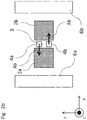
- FIG 1a One example of a known arrangement is illustrated in figure 1a , where two magnetic field detectors 4a, 4b are positioned in a slot 3 between two portions 2a, 2b of the primary conductor.
- figure 1b two magnetic field detectors 4a, 4b are positioned on opposite sides of the primary conductor 2.
- Other magnetic field sensor configurations able to measure a gradient are however also known. In the absence of external fields, the gradient of the magnetic field in the proximity of the primary conductor is proportional to the primary current I P (i.e. the current to be measured).
- the magnetic field gradient sensor comprises a first magnetic field detector 4a and a second magnetic field detector 4b positioned in a slot 3 midway between two preferably essentially identical portions 2a, 2b of a primary conductor 2 that is may for instance be in the form of a section of solid bus bar incorporated in the electrical current transducer.
- the respective sensitivity directions X a , X b of the magnetic field detectors 2a, 2b are both oriented along the X axis, but in opposite directions. They sense the X component of the magnetic flux density B .
- the two sensing elements are separated by a small distance along the Y direction. When the electric outputs of the sensors are added together, the result is proportional to dBx / dy.
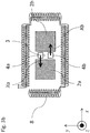
- the electrical current transducer further comprises magnetic shims 6 mounted on outer sides of the primary conductor 2.
- the magnetic shims include a first lateral magnetic shim 6a mounted adjacent an outer side of a first portion 2a of the primary conductor, and a second lateral magnetic shim 6b mounted adjacent an outer side of a second portion 2b of the primary conductor.
- a major internal surface 10 of the magnetic shims 6a, 6b, facing the magnetic field detectors 4a, 4b, extends essentially parallel to the portions 2a, 2b of a primary conductor 2 corresponding to a direction of flow of the primary current I P .
- the magnetic shims are made of a material with high magnetic permeability and low magnetic reluctance, for instance a high permeability soft magnetic material such as soft iron, ferrite or permalloy, configured to redirect external magnetic fields between the shims. Because the magnetic shims provide a path of low resistance for the external magnetic field, the external magnetic field redirected between the opposed pair of magnetic shims is homogenized as best illustrated in figures 8b and 8d . There is however an improved effect on the internal magnetic field generated by the primary conductor within the slot 3 between primary conductor portions 2a, 2b as best illustrated in figures 7a and 7b .
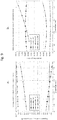
- FIG. 8a shows the field lines around the 2 square bus bar conductor portions each carrying the same current I P /2.
- the vertical line in the slot between the two conductor portions indicates the axis on which the magnetic field sensors forming the gradient sensor are located, and over which the values shown in the line plots of figures 8c and 8d are taken.
- Figure 8b shows the effect of adding the shims to the situation shown in figure 8a.
- Figure 8c shows the flux density x component along the y axis in the center of the slot, for both configurations.
- Figure 8d shows dBx / dy along the same axis. There is only a small difference in sensitivity between configurations of figure 8a and figure 8b .
- the magnetic field gradient is essentially position independent.
- the bus bar is shown carrying zero current, and a neighboring current carrying conductor is positioned at a distance of 15 mm from the center of the current transducer assembly, shown in 2 angular positions, at 0° in 11a and 11b, and at 90° in 11c and 11d.
- Figure 9a shows the X component of B along the slot axis.
- the common mode level is highest with shims and an external current neighbor at 90°, but in both cases with shims, the value of Bx along the axis is more constant than in the case without shims. This becomes clearly visible in figure 9b , which shows dBx / dy.
- rejection of inhomogeneous external fields can be improved in the order of about 5 to 10 times over conventional systems.
- the soft magnetic parts 6a, 6b thus have at their inner surface 10 an essentially magnetic equipotential, and the volume between the parallel, inside facing surfaces 10 is occupied by a substantially homogenous magnetic field.
- the dBx / dy gradient may be lower than in the absence of the soft magnetic flux shapers formed by the magnetic shims 6a, 6b, the value of Bx can be slightly higher than in the absence of the shims.
- the purpose of the soft magnetic shims in this embodiment is to shape the flux density distribution to make it more uniform, not shield or screen the magnetic sensors in the usual sense, where it is understood to result in the shielded volume having a lowered magnitude of flux density compared with the surroundings.
- the magnetic field gradient sensor comprises a first magnetic field detector 4a and a second magnetic field detector 4b positioned in a slot 3 midway between two essentially identical portions 2a, 2b of a primary conductor 2 that may for instance be in the form of a section of solid bus bar incorporated in the electrical current transducer.
- the respective sensitivity directions X a , X b of the magnetic field detectors 2a, 2b are both oriented along the X axis, but in opposite directions. They sense the X component of the magnetic flux density B .
- the two sensing elements are separated by a small distance along the Y direction.
- the electrical current transducer further comprises a Rogowski coil mounted around outer sides of the primary conductor 2.
- the magnetic field gradient sensor 4a, 4b measurement range is limited in its frequency response because the distribution of current density in a conductor bar varies with frequency (skin effect). The current distribution is dependent inter alia on conductor geometry, temperature and material properties, thus leading to a difficult to compensate behavior of the magnetic gradient measurement beyond a certain frequency.
- the Rogowski coil is however well adapted to measure the primary current I P flowing in the primary conductor 2a, 2b in a higher frequency range and complements well the magnetic field gradient sensors.
- the magnetic field gradient sensors 4a, 4b thus measure the primary current from DC up to a first threshold frequency beyond which accuracy is no longer acceptable, whereas the Rogowski coil is configured to measure the primary current with an acceptable sensitivity from a second threshold frequency up to the upper cut-off frequency of the transducer.
- the first threshold frequency of the gradient sensors is higher than the second threshold frequency where the Rogowski coil becomes usable. This allows for a transition between the two signal sources to take place at a transition frequency located in between.
- the measurement signal processing circuit may be configured to cut off the signal of the Rogowski coil below the transition frequency, respectively to cut off the signal of the magnetic field gradient sensors 4a, 4b above the transition frequency.
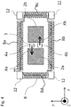
- soft magnetic corner elements 12 are provided at corners joining branches 8a, 8b, 8c, 8d of the Rogowski coil.
- the soft magnetic corner elements 12 magnetically short circuit discontinuities in the windings of the Rogowski coil formed by the corners that are present to adapt the path of the Rogowski coil to the outer profile of the primary conductor bus bar 2, 2a, 2b. This results in a better immunity to external fields.
- a primary conductor section 2, 2a, 2b, with slot 3, magnetic field gradient sensors 4a, 4b, and magnetic shims 6a, 6b are provided in a configuration similar to the embodiment of figures 2a , 2b .
- a Rogowski coil comprises two Rogowski coil branches 8a, 8b extending between the magnetic shims 6a, 6b.
- the Rogowski coil branches extend fully from the first magnetic shim 6a to the other lateral magnetic shim 6b so as to form a bridge between the shims with essentially no interruption.
- the magnetic shims 6a, 6b also serve to provide a magnetic short circuit for the Rogowski coil 8a, 8b, resulting in better immunity to external fields.
- the Rogowski coil 8 serves to measure the upper frequency range and the magnetic field gradient sensor serves to measure the lower frequency range in essentially the same manner as described above in relation to the figures 3a , 3b , whereas the effects of external fields are homogenized and attenuated by the magnetic shims 6a, 6b in essentially the same manner as described above in relation to figures 2a , 2b .
- a Rogowski coil comprises two Rogowski coil branches 8a, 8b extending between the magnetic shims 6a, 6b similar to the embodiment of figures 5a , 5b .
- the Rogowski coil branches extend fully from the first magnetic shim 6a to the other lateral magnetic shim 6b so as to form a bridge between the shims with essentially no interruption.
- the magnetic shims 6a, 6b also serve to provide a magnetic short circuit for the Rogowski coil 8a, 8b, resulting in better immunity to external fields, as described above in relation to the figures 5a , 5b .
- the Rogowski coil 8 serves to measure the upper frequency range and the magnetic field gradient sensor serves to measure the lower frequency range whereas the effects of external fields are homogenized and attenuated by the magnetic shims 6a, 6b, as described above in relation to the figures 5a , 5b .
- the transducer may therefore be alternatively or in addition configured to measure the magnetic field gradient dBy / dx. that is also transverse to the flow of the primary current
Landscapes
- Physics & Mathematics (AREA)
- General Physics & Mathematics (AREA)
- Condensed Matter Physics & Semiconductors (AREA)
- Engineering & Computer Science (AREA)
- Power Engineering (AREA)
- Measuring Instrument Details And Bridges, And Automatic Balancing Devices (AREA)
Priority Applications (8)
| Application Number | Priority Date | Filing Date | Title |
|---|---|---|---|
| EP17161460.5A EP3376238A1 (fr) | 2017-03-16 | 2017-03-16 | Transducteur de courant électrique avec capteur de gradient de champ magnétique |
| EP23168669.2A EP4235192B1 (fr) | 2017-03-16 | 2018-03-13 | Transducteur de courant électrique avec capteur de gradient de champ magnétique |
| PCT/EP2018/056131 WO2018166995A1 (fr) | 2017-03-16 | 2018-03-13 | Transducteur de courant électrique à capteur de gradient de champ magnétique |
| EP18709602.9A EP3596478B1 (fr) | 2017-03-16 | 2018-03-13 | Transducteur de courant électrique avec capteur de gradient de champ magnétique |
| JP2019550718A JP7039609B2 (ja) | 2017-03-16 | 2018-03-13 | 磁場勾配センサを備えた電流変換器 |
| CN201880018563.XA CN110431428B (zh) | 2017-03-16 | 2018-03-13 | 具有磁场梯度传感器的电流换能器 |
| US16/494,034 US11215644B2 (en) | 2017-03-16 | 2018-03-13 | Electrical current transducer with magnetic field gradient sensor |
| JP2022036193A JP7367100B2 (ja) | 2017-03-16 | 2022-03-09 | 磁場勾配センサを備えた電流変換器 |
Applications Claiming Priority (1)
| Application Number | Priority Date | Filing Date | Title |
|---|---|---|---|
| EP17161460.5A EP3376238A1 (fr) | 2017-03-16 | 2017-03-16 | Transducteur de courant électrique avec capteur de gradient de champ magnétique |
Publications (1)
| Publication Number | Publication Date |
|---|---|
| EP3376238A1 true EP3376238A1 (fr) | 2018-09-19 |
Family
ID=58358437
Family Applications (3)
| Application Number | Title | Priority Date | Filing Date |
|---|---|---|---|
| EP17161460.5A Withdrawn EP3376238A1 (fr) | 2017-03-16 | 2017-03-16 | Transducteur de courant électrique avec capteur de gradient de champ magnétique |
| EP18709602.9A Active EP3596478B1 (fr) | 2017-03-16 | 2018-03-13 | Transducteur de courant électrique avec capteur de gradient de champ magnétique |
| EP23168669.2A Active EP4235192B1 (fr) | 2017-03-16 | 2018-03-13 | Transducteur de courant électrique avec capteur de gradient de champ magnétique |
Family Applications After (2)
| Application Number | Title | Priority Date | Filing Date |
|---|---|---|---|
| EP18709602.9A Active EP3596478B1 (fr) | 2017-03-16 | 2018-03-13 | Transducteur de courant électrique avec capteur de gradient de champ magnétique |
| EP23168669.2A Active EP4235192B1 (fr) | 2017-03-16 | 2018-03-13 | Transducteur de courant électrique avec capteur de gradient de champ magnétique |
Country Status (5)
| Country | Link |
|---|---|
| US (1) | US11215644B2 (fr) |
| EP (3) | EP3376238A1 (fr) |
| JP (2) | JP7039609B2 (fr) |
| CN (1) | CN110431428B (fr) |
| WO (1) | WO2018166995A1 (fr) |
Cited By (2)
| Publication number | Priority date | Publication date | Assignee | Title |
|---|---|---|---|---|
| DE102019120666B3 (de) * | 2019-07-31 | 2020-10-29 | Dr. Ing. H.C. F. Porsche Aktiengesellschaft | Sensorvorrichtung zur breitbandigen Messung von elektrischen Strömen durch einen Leiter und Verfahren zur breitbandigen Messung |
| CN115963437A (zh) * | 2022-12-21 | 2023-04-14 | 南方电网数字电网研究院有限公司 | 多量程磁传感器、磁场测量方法及导体制备方法 |
Families Citing this family (4)
| Publication number | Priority date | Publication date | Assignee | Title |
|---|---|---|---|---|
| DE102019102567B3 (de) * | 2019-02-01 | 2020-03-05 | Dr. Ing. H.C. F. Porsche Aktiengesellschaft | Sensorvorrichtung zur Messung von Gleich- und Wechselströmen |
| EP3739345A1 (fr) | 2019-05-16 | 2020-11-18 | Siemens Aktiengesellschaft | Détection d'un courant électrique circulant dans une conduite électrique |
| EP3940396B1 (fr) * | 2020-07-16 | 2024-04-17 | Melexis Technologies SA | Capteur de courant et procédé |
| DE102021127855A1 (de) * | 2021-06-11 | 2022-12-22 | Methode Electronics Malta Ltd. | Stromsensor, der einen Magnetfeldsensor in einer V-förmigenAnordnung umfasst |
Citations (13)
| Publication number | Priority date | Publication date | Assignee | Title |
|---|---|---|---|---|
| US5621377A (en) * | 1993-01-13 | 1997-04-15 | Lust Electronic-Systeme Gmbh | Sensor assembly for measuring current as a function of magnetic field gradient |
| US6040690A (en) | 1995-01-18 | 2000-03-21 | Horstmann Timers & Controls Limited | Electricity measurement using two conductors |
| US6366076B1 (en) * | 1997-04-21 | 2002-04-02 | Liaisons Electroniques-Mecaniques Lem Sa | Device with wide passband for measuring electric current intensity in a conductor |
| US6636029B1 (en) | 1998-08-25 | 2003-10-21 | Lust Antriebstechnik Gmbh | Device and method for creating one or more magnetic field gradients through a straight conductor |
| US20040008022A1 (en) * | 2002-07-11 | 2004-01-15 | Viola Jeffrey L. | Current sensor |
| US20040201373A1 (en) * | 2003-02-26 | 2004-10-14 | Katsuhisa Kato | Current probe |
| US20050253573A1 (en) * | 2004-05-13 | 2005-11-17 | Gilles Budillon | Electric current measuring device, current sensor, electric trip unit and breaking device comprising such a measuring device |
| WO2008030129A2 (fr) * | 2006-09-06 | 2008-03-13 | Radivoje Popovic | Capteur permettant de mesurer le courant dans une barre omnibus avec correction de l'effet pelliculaire et procédé associé |
| US20090289694A1 (en) * | 2006-07-26 | 2009-11-26 | Gotthard Rieger | Current-Sensing Apparatus and Method for Current Sensing |
| WO2011097045A1 (fr) * | 2010-01-07 | 2011-08-11 | Pulse Electronics Corporation | Dispositifs détecteurs de courant et procédés associés |
| WO2013010599A1 (fr) * | 2011-07-16 | 2013-01-24 | Abb Ag | Dispositif électrique |
| EP2653876A1 (fr) * | 2012-04-20 | 2013-10-23 | ABB Technology AG | Agencement permettant de mesurer un courant avec un transducteur de courant du type Rogowski |
| WO2013181458A1 (fr) * | 2012-05-31 | 2013-12-05 | Pulse Electronics, Inc. | Dispositifs et procédés de détection de courant |
Family Cites Families (14)
| Publication number | Priority date | Publication date | Assignee | Title |
|---|---|---|---|---|
| FR2737922B1 (fr) * | 1995-08-14 | 1997-09-19 | Schneider Electric Sa | Capteur de courant et appareil electrique le comportant |
| GB9918539D0 (en) * | 1999-08-06 | 1999-10-06 | Sentec Ltd | Planar current transformer |
| EP1450176A1 (fr) * | 2003-02-21 | 2004-08-25 | Liaisons Electroniques-Mecaniques Lem S.A. | Capteur de champ magnétique et ampèremètre |
| CN1967266A (zh) * | 2006-10-29 | 2007-05-23 | 长沙同庆电气信息有限公司 | 螺旋管型空心线圈电流传感器 |
| CN201007728Y (zh) | 2007-03-06 | 2008-01-16 | 吉林大学 | 阵列式巨磁阻抗效应电流传感器 |
| US8575918B2 (en) * | 2010-03-12 | 2013-11-05 | Frank R. Stockum | Wideband transducer for measuring a broad range of currents in high voltage conductors |
| JP5616431B2 (ja) * | 2010-03-26 | 2014-10-29 | キヤノン電子株式会社 | 電流から発生する磁界を検知して電流量を推定する方法 |
| EP2423693B1 (fr) * | 2010-08-24 | 2020-02-26 | LEM International SA | Transducteur toroïdal de courant |
| IT1403434B1 (it) * | 2010-12-27 | 2013-10-17 | St Microelectronics Srl | Sensore di campo magnetico avente elementi magnetoresistivi anisotropi, con disposizione perfezionata di relativi elementi di magnetizzazione |
| KR101169301B1 (ko) * | 2011-03-04 | 2012-07-30 | 주식회사 셀픽 | 로고스키 코일을 이용한 전류센서 |
| US9310398B2 (en) * | 2011-11-29 | 2016-04-12 | Infineon Technologies Ag | Current sensor package, arrangement and system |
| JP2013148512A (ja) * | 2012-01-20 | 2013-08-01 | Aisin Seiki Co Ltd | 電流センサ |
| US9746500B2 (en) * | 2013-12-11 | 2017-08-29 | Eaton Corporation | Electrical current sensing apparatus |
| EP2921865A1 (fr) * | 2014-03-21 | 2015-09-23 | LEM Intellectual Property SA | Dispositif de détection de champ magnétique et transducteur de courant associé |
-
2017
- 2017-03-16 EP EP17161460.5A patent/EP3376238A1/fr not_active Withdrawn
-
2018
- 2018-03-13 JP JP2019550718A patent/JP7039609B2/ja active Active
- 2018-03-13 US US16/494,034 patent/US11215644B2/en active Active
- 2018-03-13 EP EP18709602.9A patent/EP3596478B1/fr active Active
- 2018-03-13 EP EP23168669.2A patent/EP4235192B1/fr active Active
- 2018-03-13 CN CN201880018563.XA patent/CN110431428B/zh active Active
- 2018-03-13 WO PCT/EP2018/056131 patent/WO2018166995A1/fr unknown
-
2022
- 2022-03-09 JP JP2022036193A patent/JP7367100B2/ja active Active
Patent Citations (13)
| Publication number | Priority date | Publication date | Assignee | Title |
|---|---|---|---|---|
| US5621377A (en) * | 1993-01-13 | 1997-04-15 | Lust Electronic-Systeme Gmbh | Sensor assembly for measuring current as a function of magnetic field gradient |
| US6040690A (en) | 1995-01-18 | 2000-03-21 | Horstmann Timers & Controls Limited | Electricity measurement using two conductors |
| US6366076B1 (en) * | 1997-04-21 | 2002-04-02 | Liaisons Electroniques-Mecaniques Lem Sa | Device with wide passband for measuring electric current intensity in a conductor |
| US6636029B1 (en) | 1998-08-25 | 2003-10-21 | Lust Antriebstechnik Gmbh | Device and method for creating one or more magnetic field gradients through a straight conductor |
| US20040008022A1 (en) * | 2002-07-11 | 2004-01-15 | Viola Jeffrey L. | Current sensor |
| US20040201373A1 (en) * | 2003-02-26 | 2004-10-14 | Katsuhisa Kato | Current probe |
| US20050253573A1 (en) * | 2004-05-13 | 2005-11-17 | Gilles Budillon | Electric current measuring device, current sensor, electric trip unit and breaking device comprising such a measuring device |
| US20090289694A1 (en) * | 2006-07-26 | 2009-11-26 | Gotthard Rieger | Current-Sensing Apparatus and Method for Current Sensing |
| WO2008030129A2 (fr) * | 2006-09-06 | 2008-03-13 | Radivoje Popovic | Capteur permettant de mesurer le courant dans une barre omnibus avec correction de l'effet pelliculaire et procédé associé |
| WO2011097045A1 (fr) * | 2010-01-07 | 2011-08-11 | Pulse Electronics Corporation | Dispositifs détecteurs de courant et procédés associés |
| WO2013010599A1 (fr) * | 2011-07-16 | 2013-01-24 | Abb Ag | Dispositif électrique |
| EP2653876A1 (fr) * | 2012-04-20 | 2013-10-23 | ABB Technology AG | Agencement permettant de mesurer un courant avec un transducteur de courant du type Rogowski |
| WO2013181458A1 (fr) * | 2012-05-31 | 2013-12-05 | Pulse Electronics, Inc. | Dispositifs et procédés de détection de courant |
Cited By (3)
| Publication number | Priority date | Publication date | Assignee | Title |
|---|---|---|---|---|
| DE102019120666B3 (de) * | 2019-07-31 | 2020-10-29 | Dr. Ing. H.C. F. Porsche Aktiengesellschaft | Sensorvorrichtung zur breitbandigen Messung von elektrischen Strömen durch einen Leiter und Verfahren zur breitbandigen Messung |
| CN115963437A (zh) * | 2022-12-21 | 2023-04-14 | 南方电网数字电网研究院有限公司 | 多量程磁传感器、磁场测量方法及导体制备方法 |
| CN115963437B (zh) * | 2022-12-21 | 2023-10-20 | 南方电网数字电网研究院有限公司 | 多量程磁传感器、磁场测量方法及导体制备方法 |
Also Published As
| Publication number | Publication date |
|---|---|
| JP2020510214A (ja) | 2020-04-02 |
| JP2022084728A (ja) | 2022-06-07 |
| JP7039609B2 (ja) | 2022-03-22 |
| EP4235192C0 (fr) | 2024-05-01 |
| EP3596478A1 (fr) | 2020-01-22 |
| EP3596478C0 (fr) | 2023-06-14 |
| CN110431428B (zh) | 2022-07-15 |
| US11215644B2 (en) | 2022-01-04 |
| WO2018166995A1 (fr) | 2018-09-20 |
| US20200088768A1 (en) | 2020-03-19 |
| CN110431428A (zh) | 2019-11-08 |
| EP4235192A3 (fr) | 2023-10-11 |
| EP4235192A2 (fr) | 2023-08-30 |
| EP4235192B1 (fr) | 2024-05-01 |
| JP7367100B2 (ja) | 2023-10-23 |
| EP3596478B1 (fr) | 2023-06-14 |
Similar Documents
| Publication | Publication Date | Title |
|---|---|---|
| EP3376238A1 (fr) | Transducteur de courant électrique avec capteur de gradient de champ magnétique | |
| US10488445B2 (en) | Current difference sensors, systems and methods | |
| KR102528062B1 (ko) | 오프셋 전류 센서 구조체 | |
| US10088505B2 (en) | Current sensor | |
| US10060953B2 (en) | Current sensor | |
| US10101413B2 (en) | Magnetic field detection device | |
| US20080106254A1 (en) | Split Rogowski coil current measuring device and methods | |
| US20200300894A1 (en) | Current sensor assembly | |
| US10545178B2 (en) | Current sensor for measuring an alternating current | |
| US20150204916A1 (en) | Electric current sensor | |
| JP6541962B2 (ja) | 電流センサおよび測定装置 | |
| US9513317B2 (en) | Current detection structure | |
| JP2021043091A (ja) | 電流センサ | |
| JP2006184269A (ja) | 電流センサ | |
| JP6582996B2 (ja) | 電流量検出器 | |
| US7911198B2 (en) | Arrangement and method for measuring a current flowing in an electrical conductor | |
| US10634703B2 (en) | Current sensor | |
| JP6671985B2 (ja) | 電流センサ | |
| JP6144597B2 (ja) | 電流センサ | |
| JP6304380B2 (ja) | 電流センサ | |
| JPH022544B2 (fr) | ||
| JP2023160700A (ja) | 電流検出器 | |
| JP2015225024A (ja) | 電流検出構造 |
Legal Events
| Date | Code | Title | Description |
|---|---|---|---|
| PUAI | Public reference made under article 153(3) epc to a published international application that has entered the european phase |
Free format text: ORIGINAL CODE: 0009012 |
|
| AK | Designated contracting states |
Kind code of ref document: A1 Designated state(s): AL AT BE BG CH CY CZ DE DK EE ES FI FR GB GR HR HU IE IS IT LI LT LU LV MC MK MT NL NO PL PT RO RS SE SI SK SM TR |
|
| AX | Request for extension of the european patent |
Extension state: BA ME |
|
| STAA | Information on the status of an ep patent application or granted ep patent |
Free format text: STATUS: THE APPLICATION IS DEEMED TO BE WITHDRAWN |
|
| 18D | Application deemed to be withdrawn |
Effective date: 20190320 |