EP3376232A1 - Kartusche - Google Patents
Kartusche Download PDFInfo
- Publication number
- EP3376232A1 EP3376232A1 EP16864156.1A EP16864156A EP3376232A1 EP 3376232 A1 EP3376232 A1 EP 3376232A1 EP 16864156 A EP16864156 A EP 16864156A EP 3376232 A1 EP3376232 A1 EP 3376232A1
- Authority
- EP
- European Patent Office
- Prior art keywords
- well
- wall surface
- sample
- cartridge
- planar portion
- Prior art date
- Legal status (The legal status is an assumption and is not a legal conclusion. Google has not performed a legal analysis and makes no representation as to the accuracy of the status listed.)
- Granted
Links
- 0 CC[C@@](C)CC*NC=* Chemical compound CC[C@@](C)CC*NC=* 0.000 description 1
Images


Classifications
-
- B—PERFORMING OPERATIONS; TRANSPORTING
- B01—PHYSICAL OR CHEMICAL PROCESSES OR APPARATUS IN GENERAL
- B01L—CHEMICAL OR PHYSICAL LABORATORY APPARATUS FOR GENERAL USE
- B01L3/00—Containers or dishes for laboratory use, e.g. laboratory glassware; Droppers
- B01L3/50—Containers for the purpose of retaining a material to be analysed, e.g. test tubes
- B01L3/508—Rigid containers without fluid transport within
- B01L3/5085—Rigid containers without fluid transport within for multiple samples, e.g. microtitration plates
- B01L3/50851—Rigid containers without fluid transport within for multiple samples, e.g. microtitration plates specially adapted for heating or cooling samples
-
- B—PERFORMING OPERATIONS; TRANSPORTING
- B01—PHYSICAL OR CHEMICAL PROCESSES OR APPARATUS IN GENERAL
- B01L—CHEMICAL OR PHYSICAL LABORATORY APPARATUS FOR GENERAL USE
- B01L3/00—Containers or dishes for laboratory use, e.g. laboratory glassware; Droppers
- B01L3/50—Containers for the purpose of retaining a material to be analysed, e.g. test tubes
- B01L3/502—Containers for the purpose of retaining a material to be analysed, e.g. test tubes with fluid transport, e.g. in multi-compartment structures
-
- B—PERFORMING OPERATIONS; TRANSPORTING
- B01—PHYSICAL OR CHEMICAL PROCESSES OR APPARATUS IN GENERAL
- B01L—CHEMICAL OR PHYSICAL LABORATORY APPARATUS FOR GENERAL USE
- B01L3/00—Containers or dishes for laboratory use, e.g. laboratory glassware; Droppers
-
- B—PERFORMING OPERATIONS; TRANSPORTING
- B01—PHYSICAL OR CHEMICAL PROCESSES OR APPARATUS IN GENERAL
- B01L—CHEMICAL OR PHYSICAL LABORATORY APPARATUS FOR GENERAL USE
- B01L3/00—Containers or dishes for laboratory use, e.g. laboratory glassware; Droppers
- B01L3/52—Containers specially adapted for storing or dispensing a reagent
- B01L3/527—Containers specially adapted for storing or dispensing a reagent for a plurality of reagents
-
- G—PHYSICS
- G01—MEASURING; TESTING
- G01N—INVESTIGATING OR ANALYSING MATERIALS BY DETERMINING THEIR CHEMICAL OR PHYSICAL PROPERTIES
- G01N35/00—Automatic analysis not limited to methods or materials provided for in any single one of groups G01N1/00 - G01N33/00; Handling materials therefor
- G01N35/02—Automatic analysis not limited to methods or materials provided for in any single one of groups G01N1/00 - G01N33/00; Handling materials therefor using a plurality of sample containers moved by a conveyor system past one or more treatment or analysis stations
- G01N35/026—Automatic analysis not limited to methods or materials provided for in any single one of groups G01N1/00 - G01N33/00; Handling materials therefor using a plurality of sample containers moved by a conveyor system past one or more treatment or analysis stations having blocks or racks of reaction cells or cuvettes
-
- G—PHYSICS
- G01—MEASURING; TESTING
- G01N—INVESTIGATING OR ANALYSING MATERIALS BY DETERMINING THEIR CHEMICAL OR PHYSICAL PROPERTIES
- G01N35/00—Automatic analysis not limited to methods or materials provided for in any single one of groups G01N1/00 - G01N33/00; Handling materials therefor
- G01N35/02—Automatic analysis not limited to methods or materials provided for in any single one of groups G01N1/00 - G01N33/00; Handling materials therefor using a plurality of sample containers moved by a conveyor system past one or more treatment or analysis stations
- G01N35/028—Automatic analysis not limited to methods or materials provided for in any single one of groups G01N1/00 - G01N33/00; Handling materials therefor using a plurality of sample containers moved by a conveyor system past one or more treatment or analysis stations having reaction cells in the form of microtitration plates
-
- B—PERFORMING OPERATIONS; TRANSPORTING
- B01—PHYSICAL OR CHEMICAL PROCESSES OR APPARATUS IN GENERAL
- B01L—CHEMICAL OR PHYSICAL LABORATORY APPARATUS FOR GENERAL USE
- B01L2200/00—Solutions for specific problems relating to chemical or physical laboratory apparatus
- B01L2200/06—Fluid handling related problems
- B01L2200/0605—Metering of fluids
-
- B—PERFORMING OPERATIONS; TRANSPORTING
- B01—PHYSICAL OR CHEMICAL PROCESSES OR APPARATUS IN GENERAL
- B01L—CHEMICAL OR PHYSICAL LABORATORY APPARATUS FOR GENERAL USE
- B01L2300/00—Additional constructional details
- B01L2300/02—Identification, exchange or storage of information
- B01L2300/025—Displaying results or values with integrated means
- B01L2300/028—Graduation
-
- B—PERFORMING OPERATIONS; TRANSPORTING
- B01—PHYSICAL OR CHEMICAL PROCESSES OR APPARATUS IN GENERAL
- B01L—CHEMICAL OR PHYSICAL LABORATORY APPARATUS FOR GENERAL USE
- B01L2300/00—Additional constructional details
- B01L2300/08—Geometry, shape and general structure
- B01L2300/0848—Specific forms of parts of containers
- B01L2300/0858—Side walls
-
- B—PERFORMING OPERATIONS; TRANSPORTING
- B01—PHYSICAL OR CHEMICAL PROCESSES OR APPARATUS IN GENERAL
- B01L—CHEMICAL OR PHYSICAL LABORATORY APPARATUS FOR GENERAL USE
- B01L2300/00—Additional constructional details
- B01L2300/08—Geometry, shape and general structure
- B01L2300/0861—Configuration of multiple channels and/or chambers in a single devices
-
- G—PHYSICS
- G01—MEASURING; TESTING
- G01N—INVESTIGATING OR ANALYSING MATERIALS BY DETERMINING THEIR CHEMICAL OR PHYSICAL PROPERTIES
- G01N35/00—Automatic analysis not limited to methods or materials provided for in any single one of groups G01N1/00 - G01N33/00; Handling materials therefor
- G01N35/02—Automatic analysis not limited to methods or materials provided for in any single one of groups G01N1/00 - G01N33/00; Handling materials therefor using a plurality of sample containers moved by a conveyor system past one or more treatment or analysis stations
- G01N35/04—Details of the conveyor system
- G01N2035/0401—Sample carriers, cuvettes or reaction vessels
- G01N2035/0412—Block or rack elements with a single row of samples
Definitions
- the present invention relates to a cartridge used when a component to be measured contained in a fluid is measured.
- Patent Literature 1 Japanese Unexamined Patent Application Publication No. 2009-150912
- a possible solution may be forming highly visible scale marks on the inner wall surface of a well.
- undercuts have to be made on the scale marks during injection molding, which makes it difficult to produce wells.
- an injected sample may adhere to the scale marks, with the result that a sample in an amount required for measurement cannot be taken.
- An object of the present invention is to provide a cartridge that prevents a fluid from overflowing from a well and exposing the user to a biohazard and that ensures that a required amount of fluid can be taken.
- a cartridge according to the present invention is:
- the cartridge according to the prevent invention can ensure that a fluid is prevented from overflowing from a well and exposing the user to a biohazard.
- the cartridge of the present invention includes the following:
- the cartridge of the present invention is:
- the user when a fluid is injected into the well, the user can visually recognize that a required amount of fluid has been injected into the well, and the user is prevented from being exposed to a biohazard attributable to a fluid overflowing from the well.
- the step includes a planar portion having a predetermined width and being formed along the inner wall surface of the well.
- the user can visually recognize that a required amount of fluid has been injected into the well because the area of the fluid surface abruptly extends at the planar portion, which serves as a marked line.
- the well's bottom end is a bottom face
- the planar portion is formed to be flat and all parts of the planar portion are formed at a certain height from the bottom face.
- an angle formed by a plumb line to the bottom face and a line perpendicular to the planar portion is in a range of 0° to 20°.
- the area of the fluid surface is allowed to abruptly extend when the level of the fluid surface reaches the planar portion.
- the step includes a rising wall surface that connects an outer perimeter of the planar portion and an inner perimeter of a bottom end of the upper space.
- an angle formed by the plumb line to the bottom face and a line perpendicular to the rising wall surface is in a range of 70° to 90°.
- the planar portion is colored or roughened.
- the position of the planar portion serving as a marked line can be made distinct.
- the rising wall surface is colored or roughened.
- the plumb line to the opening that is formed on the top end of the upper space is decentered with respect to the plumb line to the bottom face.
- the user can bring the tip of a syringe, a micropipettor, or any other injection tool closer to the inner wall surface side to inject a fluid while seeing the bottom face.
- an inclination angle formed by the inner wall surface of the upper space and the plumb line to the opening is an inclination angle between 0.5° and 70°.
- a gradient needed for injection-molding the well can be obtained.
- the obtained gradient does not prevent a fluid from flowing to the bottom face.
- surface roughness of at least one of the planar portion and the rising wall surface is between Ra 0.05 ⁇ m and Ra 5 ⁇ m.
- surface roughness can be obtained to the extent that the position of a marked line is clearly visible, as well as to the extent that a fluid is not prevented from flowing to the bottom face.
- a planar shape of the well seen from above the opening is any one of circular, oval, and substantially oval with both ends of a rectangular having arc-shaped ends.
- the fluid is a sample or a reagent.
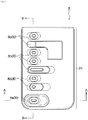
- FIG. 1 is a plan view illustrating a surface of the cartridge according to the embodiment
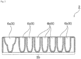
- Fig. 2 is a cross-sectional view of the cartridge according to the embodiment taken along B-B in Fig. 1 .
- the cartridge 2 which is formed of a resin material such as polypropylene, is a rectangular plate in plan view including a well forming portion 2b in which a plurality of recessed wells 6 are formed for storing samples to be used for an experiment.
- Each of the wells 6 has its opening that is formed to elongate from a region where the wells 6 are located on the well forming portion 2b of the cartridge 2 (the left-hand region in Fig. 1 ) to a region where none of the wells 6 are located (the right-hand region in Fig. 1 ).
- the wells 6 include a sample well 6a into which the user directly injects a sample, and a reagent well 6b into which a reagent is injected.
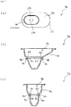
- Fig. 3 illustrates a structure of the sample well 6a.
- Fig. 3A is a top view of the sample well 6a
- Fig. 3B is a cross-sectional view of the sample well 6a taken along A-A in Fig. 1
- Fig. 3C is a cross-sectional view of the sample well 6a taken along B-B in Fig. 1 .
- the sample well 6a includes an upper barrel portion 8 in the shape of a substantially inverted cone, a step portion 9 in the shape of a ring integrally connected to the bottom end of the upper barrel portion 8, and a lower barrel portion 10 in the shape of an inverted cone integrally connected to the step portion 9.
- the sample well 6a is, at any height, in a substantially oval shape with arcs formed at both ends of a rectangular in cross section.
- the upper barrel portion 8 includes an upper peripheral wall 8a having a predetermined thickness, with an upper space 8b formed in a region surrounded by the upper peripheral wall 8a. On top of the upper space 8b, an opening 12 is formed for supplying a sample.
- the upper peripheral wall 8a is inwardly inclined from the opening 12 side toward a bottom face 10c located on the lower side, and thus the upper space 8b decreases in cross-sectional area as the area is closer to the bottom face 10c.
- the upper peripheral wall 8a is formed so that its inner wall surface forms an inclination angle of 0.5 to 70° with a plumb line X1 to the opening 12.
- a left side wall 11a in Fig. 3B and side walls 11b and 11c in Fig. 3C each form an inclination angle to make a steep slope
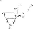
- a right side wall 11d in Fig. 3B forms an inclination angle ⁇ to make a gentle slope.
- the plumb line X1 to the opening 12 is shifted from the plump line X2 to the bottom face 10c (the plumb line X2 is parallel to the plumb line X1), and accordingly the sample well 6a is structured to be vertically eccentric.
- the sample well 6a is structured to be vertically eccentric in order to allow the user to bring the tip of the syringe closer to the right side wall 11d to inject a sample while seeing the bottom face 10c, as illustrated in Fig. 4 .
- the amount of eccentricity is preferably 1 mm or more because the tip of a syringe is usually ⁇ 1 mm in diameter.
- An inclination angle of 0.5° or more is preferable because of easier removal from the mold during injection molding, which makes the production easier.
- An inclination angle of 70° or less is preferable because a sample injected into the sample well 6a can flow to the bottom face 10c to reduce any sample adhering to the well, which makes it possible to take a predetermined amount of sample for detection. The aforementioned range was confirmed by the present inventors through experiments.
- the step portion 9 is L-shaped in cross section.
- the L shape includes a floor portion 9a on one part of the L shape and a rising wall portion 9b on the other part of the L shape, the rising wall portion 9b rising from the floor portion 9a toward the opening 12 side.
- a planar portion 9c having a predetermined width is formed on the inner wall side of the floor portion 9a.
- a rising wall surface 9d having a predetermined height is formed.
- a step made of the planar portion 9c and the rising wall portion 9b is formed between the upper space 8b and a lower space 10b (described later).
- the cross-sectional area on the top end of the lower space 10b is smaller than the cross-sectional area on the bottom end of the upper space 8b.
- the planar portion 9c is formed in the shape of a ring along the inner wall surface of the sample well 6a, and is continuously connected to the top end of the inner wall surface of a lower peripheral wall 10a, which is described later.
- the planar portion 9c is formed to be flat without being distorted up and down. That is, every part of the planar portion 9c is formed to be at a predetermined height from the bottom face 10c.
- the planar portion 9c is formed so that the angle formed by the plumb line X2 and a line (not illustrated) perpendicular to the planar portion 9c is between 0° and 20°. Nevertheless, it is preferable that the planar portion 9c is not inclined as illustrated in Figs. 3B and 3C , and thus the angle formed by the plumb line X2 and a line perpendicular to the planar portion 9c is desirably 0°.
- the width of the planar portion 9c is preferably between 0.4 mm and 0.7 mm.
- the planar portion 9c having a width of 0.4 mm or more as above is preferable because a situation, such as failure in forming the planar portion 9c caused by chamfering performed during mold production, can be prevented, and thus the planar portion 9c can be easily formed into an accurate shape.
- the planar portion 9c having a width of 0.7 mm or less is preferable because the amount of a sample adhering to the planar portion 9c can be reduced. More preferably, the planar portion 9c has a width of about 0.5 mm.
- the rising wall surface 9d is formed along the inner wall surface of the sample well 6a so as to continuously join the outer perimeter of the planar portion 9c and the inner wall surface of the bottom end of the upper space 8b. Concerning the inclination angle of the rising wall surface 9d, the rising wall surface 9d is formed so that the angle formed by the plumb line X2 and a line (not illustrated) perpendicular to the rising wall surface 9d is between 70° and 90°. Nevertheless, it is preferable that the rising wall surface 9d is not inclined, and thus the angle formed by the plumb line X2 and a line perpendicular to the rising wall surface 9d is desirably 90°.
- the height of the rising wall surface 9d is preferably between 0.3 mm and 1.0 mm.
- the rising wall surface 9d having a height of 0.3 mm or more as above is preferable because the rising wall surface 9d can be easily formed into an accurate shape.
- the rising wall surface 9d having a height of 1.0 mm or less is preferable because the amount of a sample adhering to a corner between the rising wall surface 9d and the planar portion 9c can be reduced.
- the lower barrel portion 10 includes a lower peripheral wall 10a having a predetermined thickness, with the lower space 10b formed in a region surrounded by the lower peripheral wall 10a.
- the bottom end of the lower space 10b is closed with the bottom face 10c.
- the lower peripheral wall 10a is also inwardly inclined from the opening 12 side toward the bottom face 10c located on the lower side, and thus the lower space 10b decreases in cross-sectional area as the area is closer to the bottom face 10c side.
- the cartridge 2 is prepared with the sample well 6a being empty as illustrated in Figs. 3A to 3C .
- the user prepares a syringe and injects a sample out of the syringe into the sample well 6a.
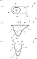
- Figs. 5A to 5C illustrate the state in which the sample has been injected into the sample well 6a to the extent that the fluid surface reaches the height of the planar portion 9c.
- the sample When the fluid surface exceeds the height of the planar portion 9c as illustrated in Figs. 6A to 6C , the sample enters the step space formed on the planar portion 9c and the area of the fluid surface suddenly extends. This enables the user to visually recognize that a required amount of sample has been injected into the sample well 6a.
- the planar portion 9c functions as a marked line for letting the user know that a required amount of sample has been injected into the sample well 6a.
- the rising wall surface 9d is not inclined, further injection of the sample makes the fluid surface keep rising without changing the area of the fluid surface for a while.
- the fluid surface keeps on rising without changing its area for a while after the fluid level of the sample reaches the planar portion 9c.
- the user can be definitely aware that a required amount of sample has been injected into the sample well 6a even when the user cannot see a momentary change in the area of the fluid surface.
- the fluid surface area of the sample again extends.
- the top end of the rising wall surface 9d functions as a marked line indicating a permissible upper limit for injecting a sample. Accordingly, the user can confirm twice that a required amount of sample has been injected into the sample well 6a.
- the cartridge 2 includes the step portion 9 disposed between the upper barrel portion 8 and the lower barrel portion 10 of the sample well 6a, with the planar portion 9c having a predetermined width and formed on the step portion 9.
- the planar portion 9c and the top end of the rising wall surface 9d serve as marked lines when a sample is injected into the sample well 6a, enabling the user to visually identify whether a required amount of sample has been injected into the sample well 6a. Consequently, a sample is prevented from overflowing from the sample well 6a and exposing the user to a biohazard.
- the step portion 9 which is L-shaped in cross section, has a simple structure in which the planar portion 9c and the rising wall surface 9d are formed on the inner wall surface side of the sample well 6a.
- the sample well 6a includes the planar portion 9c and the rising wall surface 9d, both of which are simple in structure, and thus a sample is less likely to adhere to, and stay on, a scale mark, like the case where a protruding scale mark is formed on the inner wall surface. Therefore, a sample in an amount required for measurement can be successfully taken.
- the planar shape of the sample well 6a with respect to the height direction is made substantially oval, a sample is less likely to stay on the sample well than a rectangular planar shape of the sample well 6a with respect to the height direction.
- planar portion 9c in the foregoing embodiment may be colored with, for example, an oil-based black ink as shown in Fig. 7 . This ensures that the user visually recognizes the marked line for injecting a required amount of sample. Either or both of the rising wall surface 9d and the planar portion 9c may be colored. Alternatively, to strictly prohibit an ink or any other paint from mixing with a sample, the coloring may be given to the outer wall side of the floor portion 9a of the step portion 9 and to the outer wall side of the rising wall portion 9b.
- a roughening process may be performed on the planar portion 9c. Since resin materials such as polystyrene are usually milky-white transparent, the planar portion 9c becomes white-fogged when roughened, exerting an effect similar to being colored.
- the roughening process may be performed on either or both of the planar portion 9c and the rising wall surface 9d. Alternatively, to strictly prohibit the roughness from taking a sample to reduce the amount of sample drawn from the sample well 6a, the roughening process may be performed on the outer wall side of the floor portion 9a of the step portion 9 and on the outer wall side of the rising wall portion 9b.
- the planar portion 9c, the rising wall surface 9d, the outer wall surface of the floor portion 9a, and/or the outer wall surface of the rising wall portion 9b preferably has surface roughness between Ra 0.05 ⁇ m and Ra 5 ⁇ m.
- a surface roughness of Ra 0.05 ⁇ m or more is preferable because a change in color caused by the surface roughness can further improve the visibility.
- a surface roughness of Ra 5 ⁇ m or less is preferable because a sample injected into the sample well 6a can flow to the bottom face 10c to reduce any sample adhering to the well, which makes it possible to take a predetermined amount of sample for detection. The aforementioned range was confirmed by the present inventors through experiments.
- the step portion 9 is formed on the whole perimeter of the sample well 6a.
- the step portion 9 may be formed on part of the perimeter.
- the user can still visually recognize that a required amount of sample has been injected into the sample well 6a because the area of the fluid surface of an injected sample abruptly extends at the step portion 9.
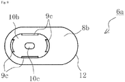
- the planar portion 9c is preferably disposed on at least four locations so that the user can be aware that the sample well 6a is not inclined.
- the planar portion 9c is preferably disposed on each of the four locations on the inner wall surface of the sample well 6a, as illustrated in Fig. 9 .
- the rising wall surface 9d may not necessarily be present.
- the inner wall surface of the upper peripheral wall 8a may be directly coupled to the outer perimeter of the planar portion 9c.
- the sample well 6a is simpler in structure, making it easier to form the sample well 6a.
- possible methods for producing the cartridge 2 include cutting, cast molding, and injection molding involving a mold.
- possible methods for producing the cartridge 2 include cutting, cast molding, and injection molding involving a mold.
- injection molding it is preferable to use injection molding to produce the cartridge 2.
- possible materials of members forming the cartridge 2 include chemical-resistant glass, metal, and resins being less likely to cause chemical reactions with a reagent or a sample.
- resins it is preferable to use resins.
- Such resin materials may include noncrystalline resins such as polycarbonate (PC), acrylic resin (PMMA), and polystyrene (PS) as well as crystalline resins such as polyethylene (PE) and polypropylene (PP).
- PC polycarbonate
- PMMA acrylic resin
- PS polystyrene
- crystalline resins such as polyethylene (PE) and polypropylene (PP).
- PE polyethylene
- PP polypropylene
- a required amount of reagent is injected into, and stored in, the reagent well 6b in advance after the cartridge 2 is molded.
- the top face of the reagent well 6b is preferably sealed with a seal or the like after a reagent is injected. This prevents the reagent from spilling from the reagent well 6b when the user carries the cartridge 2, and thus the cartridge 2 is easier to handle. Sealing the top face of the reagent well 6b also allows the reagent to be stored without contamination or mixture with foreign substances. No particular limitation is imposed on materials of the seal or sealing methods. Each individual reagent well 6b may be formed in accordance with the intended use.
- the step portion 9 is disposed on the sample well 6a into which the user injects a sample.
- the step portion 9 may also be disposed on the reagent well 6b.
- the planar portion 9c serves as a marked line, and thus the user can visually recognize that a required amount of reagent has been injected into the reagent well 6b.
- the plumb line X1 to the opening 12 in the sample well 6a is shifted to the right in Fig. 3 and decentered with respect to the the plumb line X2 to the bottom face 10c.
- the direction of decentering is not limited to this.
- the plumb line X1 may be decentered to the left with respect to the the plumb line X2.
- planar shape of the well 6 seen from above the opening 12 may be circular or oval.
- the cartridge 2 is rectangular in plan view so that the user can easily hold the cartridge 2 in his/her hand.
- the cartridge 2 may not necessarily be rectangular in plan view.
- each of the cartridges 2 used for the experiments is a translucent milky-white cartridge made from polypropylene, 60 mm long, 30 mm wide, and 17 mm high, with all the parts including the sample well 6a having a thickness of 1 mm.
- each of the cartridges 2 a required amount of reagent was injected into the reagent wells 6b, and then every reagent well 6b was sealed on its top face by bonding a 0.02 mm thick aluminum seal onto the surface of the well forming portion 2b through thermocompression bonding.
- test fluid was a solution being colored in red and having a viscosity equal to that of a blood sample.
- a needleless syringe having an inner diameter of ⁇ 10 mm and a capacity of 10 cc (see Fig. 4 ) was used for injecting the sample.
- Example 1 represents an experiment conducted on the cartridge 2, which is one of the aforementioned seven cartridges 2 and includes the sample well 6a in the shape presented in Fig. 3 (hereinafter called the shape 1 sample well).
- the depth from the opening 12 to the bottom face 10c (hereinafter simply called the depth) was 14 mm
- the longest length of the opening 12 (hereinafter simply called the opening length) was 19.5 mm
- the width of the opening 12 (hereinafter simply called the opening width) was 10 mm
- the distance between the plumb line X1 and the plumb line X2 hereinafter simply called the decentering distance) was 3 mm
- the width of the planar portion 9c (hereinafter simply called the planar width) was 0.5 mm
- the height of the rising wall surface 9d (hereinafter simply called the rising height) was 0.7 mm.
- the experiment conducted on the shape 1 sample well demonstrated that the sample could be accurately injected up to the marked line, that is the height of the planar portion 9c, because it was easy to identify a change in speed of the fluid surface of the sample being injected, and it was also easy to visually recognize the planar portion 9c.
- the shape 1 sample well was evaluated as " ⁇ " as shown in the table in Fig. 13 .
- Example 2 represents an experiment conducted on the cartridge 2 including the sample well 6a in which the planar portion 9c on the shape 1 well was colored (hereinafter called the shape 2 sample well), as illustrated in Fig. 7 .
- the shape 2 sample well was the same as the shape 1 sample well in size of the well and inclination angle of the inner wall surface of the upper peripheral wall 8a.
- the experiment conducted on the shape 2 sample well demonstrated that a required amount of sample could be easily injected because of higher visibility of the planar portion 9c than that of the shape 1 sample well owing to the change in color of the planar portion 9c. Therefore, the shape 2 sample well was evaluated as " ⁇ " as shown in the table in Fig. 13 .
- Example 3 represents an experiment conducted on the cartridge 2 including the sample well 6a in which the planar portion 9c on the shape 1 well was roughened (hereinafter called the shape 3 sample well), as illustrated in Fig. 8 .
- the shape 3 sample well was the same as the shape 1 sample well in size of the well and inclination angle of the inner wall surface of the upper peripheral wall 8a.
- Example 4 represents an experiment conducted on the cartridge 2 including the sample well 6a that is a modification of the shape 1 well and that includes the planar portion 9c being formed on each of the four locations on the inner wall surface of the sample well 6a (hereinafter called the shape 4 sample well), as illustrated in Fig. 9 .
- the shape 3 sample well was the same as the shape 1 sample well in size of the well and inclination angle of the inner wall surface of the upper peripheral wall 8a.
- the experiment conducted on the shape 4 sample well demonstrated that the sample could be injected up to the marked line, that is the height of the planar portion 9c, because it was easy to identify a change in speed of the fluid surface of the sample being injected, and it was also easy to visually recognize the planar portion 9c.
- visibility of the planar portion 9c was lower than that of the shape 1 sample well because the planar portion 9c was not formed on every part of the perimeter of the inner wall surface of the sample well 6a, and thus the step serving as a marked line was missing in the region where the planar portion 9c was not formed. Therefore, the shape 4 sample well was evaluated as " ⁇ " as shown in the table in Fig. 13 .
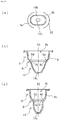
- Example 5 represents an experiment conducted on the cartridge 2 including the sample well 6a that is a modification of the shape 1 well and that directly couples the inner wall surface of the upper peripheral wall 8a to the outer perimeter of the planar portion 9c (hereinafter called the shape 5 sample well), as illustrated in Fig. 10 .
- the shape 5 sample well was the same as the shape 1 sample well in size except that the rising height was absent. Concerning inclination angles of the inner wall surface of the upper peripheral wall 8a illustrated in Fig.
- the inclination angle (not illustrated) formed by the inner wall surface of the left side wall 11a and the central axis X1 was 14°
- the inclination angle (not illustrated) formed by the inner wall surface of the right side wall 11d and the central axis X1 was 55°.
- the experiment conducted on the shape 5 sample well demonstrated that the sample could be injected up to the marked line, that is the height of the planar portion 9c, because it was easy to identify a change in speed of the fluid surface of the sample being injected, and it was also easy to visually recognize the planar portion 9c.
- visibility of the planar portion 9c was lower than that of the shape 1 sample well because of the absence of the rising wall surface 9d.
- a marked line indicating a permissible upper limit of the sample was lost. Therefore, the shape 5 sample well was evaluated as " ⁇ " as shown in the table in Fig. 13 .
- Example 6 represents an experiment conducted on the cartridge 2 including the sample well that is a modification of the shape 1 well and that includes a single plumb line X identical to the plumb line X2 to the bottom face 10c, as illustrated in Fig. 11 , to remove eccentricity in the upper barrel portion 8 (hereinafter called the shape 6 sample well).
- the shape 6 sample well was the same as the shape 1 sample well in size except that the shape 6 sample well had a shorter opening length, 13.8 mm, because of no decentering distance. Concerning inclination angles of the inner wall surface of the upper peripheral wall 8a illustrated in Fig.
- both the inclination angle (not illustrated) formed by the inner wall surface of the left side wall 11a and the plumb line X2 and the inclination angle (not illustrated) formed by the inner wall surface of the right side wall 11d and the plumb line X2 were 10°.
- Comparative Example 1 represents an experiment conducted on the cartridge 2 including the sample well that is a modification of the shape 1 well to eliminate the step portion 9, as illustrated in Fig. 12 (hereinafter called the shape 7 sample well).
- the shape 7 sample well was the same as the shape 1 sample well in size of the well and inclination angle of the inner wall surface of the upper peripheral wall 8a, except for the absence of the planar width and the rising height.
Landscapes
- Chemical & Material Sciences (AREA)
- Health & Medical Sciences (AREA)
- Chemical Kinetics & Catalysis (AREA)
- General Health & Medical Sciences (AREA)
- Analytical Chemistry (AREA)
- Clinical Laboratory Science (AREA)
- Physics & Mathematics (AREA)
- Life Sciences & Earth Sciences (AREA)
- Biochemistry (AREA)
- General Physics & Mathematics (AREA)
- Immunology (AREA)
- Pathology (AREA)
- Hematology (AREA)
- Medicinal Chemistry (AREA)
- Automatic Analysis And Handling Materials Therefor (AREA)
- Optical Measuring Cells (AREA)
- Devices For Use In Laboratory Experiments (AREA)
Priority Applications (1)
| Application Number | Priority Date | Filing Date | Title |
|---|---|---|---|
| EP20177344.7A EP3722814B1 (de) | 2015-11-13 | 2016-11-07 | Kartusche |
Applications Claiming Priority (2)
| Application Number | Priority Date | Filing Date | Title |
|---|---|---|---|
| JP2015223368 | 2015-11-13 | ||
| PCT/JP2016/082940 WO2017082195A1 (ja) | 2015-11-13 | 2016-11-07 | カートリッジ |
Related Child Applications (2)
| Application Number | Title | Priority Date | Filing Date |
|---|---|---|---|
| EP20177344.7A Division EP3722814B1 (de) | 2015-11-13 | 2016-11-07 | Kartusche |
| EP20177344.7A Division-Into EP3722814B1 (de) | 2015-11-13 | 2016-11-07 | Kartusche |
Publications (3)
| Publication Number | Publication Date |
|---|---|
| EP3376232A4 EP3376232A4 (de) | 2018-09-19 |
| EP3376232A1 true EP3376232A1 (de) | 2018-09-19 |
| EP3376232B1 EP3376232B1 (de) | 2020-12-23 |
Family
ID=58695255
Family Applications (2)
| Application Number | Title | Priority Date | Filing Date |
|---|---|---|---|
| EP20177344.7A Active EP3722814B1 (de) | 2015-11-13 | 2016-11-07 | Kartusche |
| EP16864156.1A Active EP3376232B1 (de) | 2015-11-13 | 2016-11-07 | Kartusche |
Family Applications Before (1)
| Application Number | Title | Priority Date | Filing Date |
|---|---|---|---|
| EP20177344.7A Active EP3722814B1 (de) | 2015-11-13 | 2016-11-07 | Kartusche |
Country Status (5)
| Country | Link |
|---|---|
| US (1) | US11534764B2 (de) |
| EP (2) | EP3722814B1 (de) |
| JP (1) | JP6708215B2 (de) |
| ES (1) | ES2978532T3 (de) |
| WO (1) | WO2017082195A1 (de) |
Cited By (2)
| Publication number | Priority date | Publication date | Assignee | Title |
|---|---|---|---|---|
| EP3965932B1 (de) * | 2019-05-08 | 2024-08-14 | Scienion GmbH | Testplatte mit nanogefässen und probenrückgewinnungsvorrichtung |
| EP4571312A3 (de) * | 2018-02-02 | 2025-12-24 | Nippon Chemiphar Co., Ltd. | Biochemisches reaktionssubstrat und analysegerät |
Families Citing this family (4)
| Publication number | Priority date | Publication date | Assignee | Title |
|---|---|---|---|---|
| USD836793S1 (en) * | 2016-07-22 | 2018-12-25 | Meso Scale Technologies, Llc. | Cartridge |
| JP7003763B2 (ja) * | 2018-03-19 | 2022-02-04 | 凸版印刷株式会社 | 試薬カートリッジ |
| JP7172745B2 (ja) | 2019-03-06 | 2022-11-16 | 株式会社Jvcケンウッド | 分析用ユニット、洗浄装置、及び洗浄方法 |
| WO2021020547A1 (ja) * | 2019-08-01 | 2021-02-04 | 日本ケミファ株式会社 | 試薬カートリッジ |
Family Cites Families (14)
| Publication number | Priority date | Publication date | Assignee | Title |
|---|---|---|---|---|
| US4150089A (en) * | 1977-09-06 | 1979-04-17 | Linet Michael S | Multi-chamber test tube |
| JPH09101302A (ja) | 1995-10-06 | 1997-04-15 | Toppan Printing Co Ltd | マイクロプレート |
| US20020057995A1 (en) * | 2000-09-15 | 2002-05-16 | Guido Desie | Microtiter plate |
| ES2300738T3 (es) * | 2003-01-17 | 2008-06-16 | Nextal Biotechnologie Inc. | Placas de cristalizacion precargadas y procedimientos para preparacion y uso de las mismas. |
| EP1650570B1 (de) | 2003-07-17 | 2021-05-26 | LSI Medience Corporation | Gerät zur verwendung zur messung einer komponente, die in einer probe enthalten ist, die ein messgerät und eine kartusche enthält |
| EP1621890A1 (de) | 2004-07-26 | 2006-02-01 | bioMerieux B.V. | Gerät und Methode zur Separation, Mischung und Konzentrierung magnetischer Partikel mit Flüssigkeiten und deren Verwendungen in Reinigungsmethoden |
| US8968679B2 (en) * | 2005-05-19 | 2015-03-03 | Emd Millipore Corporation | Receiver plate with multiple cross-sections |
| WO2007076023A2 (en) * | 2005-12-21 | 2007-07-05 | Meso Scale Technologies, Llc | Assay modules having assay reagents and methods of making and using same |
| DK1880764T3 (da) * | 2006-07-20 | 2012-12-17 | Ibidi Gmbh | Prøveholder til undersøgelse af cellevækst |
| CN102046773A (zh) * | 2008-05-30 | 2011-05-04 | 康宁股份有限公司 | 具有不同微孔外形的细胞培养装置 |
| JP2010032487A (ja) | 2008-06-26 | 2010-02-12 | Olympus Corp | 解析用容器及び生化学的解析方法 |
| JP2011128019A (ja) * | 2009-12-17 | 2011-06-30 | Hitachi Maxell Ltd | マイクロプレートデバイスおよびその利用方法 |
| US20130183769A1 (en) * | 2010-09-17 | 2013-07-18 | Universal Bio Research Co., Ltd. | Cartridge and automatic analysis device |
| US20160103061A1 (en) * | 2014-09-12 | 2016-04-14 | Analytik Jena Ag | Reaction Vessel, Reaction Vessel Arrangement and Method for Analyzing a Substance |
-
2016
- 2016-11-07 ES ES20177344T patent/ES2978532T3/es active Active
- 2016-11-07 EP EP20177344.7A patent/EP3722814B1/de active Active
- 2016-11-07 WO PCT/JP2016/082940 patent/WO2017082195A1/ja not_active Ceased
- 2016-11-07 JP JP2017550302A patent/JP6708215B2/ja active Active
- 2016-11-07 US US15/770,667 patent/US11534764B2/en active Active
- 2016-11-07 EP EP16864156.1A patent/EP3376232B1/de active Active
Cited By (2)
| Publication number | Priority date | Publication date | Assignee | Title |
|---|---|---|---|---|
| EP4571312A3 (de) * | 2018-02-02 | 2025-12-24 | Nippon Chemiphar Co., Ltd. | Biochemisches reaktionssubstrat und analysegerät |
| EP3965932B1 (de) * | 2019-05-08 | 2024-08-14 | Scienion GmbH | Testplatte mit nanogefässen und probenrückgewinnungsvorrichtung |
Also Published As
| Publication number | Publication date |
|---|---|
| EP3376232A4 (de) | 2018-09-19 |
| EP3722814A1 (de) | 2020-10-14 |
| WO2017082195A1 (ja) | 2017-05-18 |
| ES2978532T3 (es) | 2024-09-13 |
| US20180311668A1 (en) | 2018-11-01 |
| JP6708215B2 (ja) | 2020-06-10 |
| JPWO2017082195A1 (ja) | 2018-08-30 |
| EP3376232B1 (de) | 2020-12-23 |
| EP3722814B1 (de) | 2024-03-20 |
| US11534764B2 (en) | 2022-12-27 |
Similar Documents
| Publication | Publication Date | Title |
|---|---|---|
| EP3722814B1 (de) | Kartusche | |
| CN201380075Y (zh) | 用于分析液体的容器 | |
| US5260030A (en) | Calibrated pipette tip and method | |
| US6663018B2 (en) | Liquid supply assembly | |
| US4647419A (en) | Method and apparatus for producing a flash free pipette | |
| US8813563B2 (en) | Measuring cup | |
| EP1857777B1 (de) | Nivellierinstrument, Libelle und Herstellungsverfahren dafür | |
| EP3183061B1 (de) | Pipettenspitzen mit erweiterten attributen und verfahren zur herstellung davon | |
| EP2512678A1 (de) | Mikropipette | |
| CA2752863A1 (en) | Method and device for providing blood constituents | |
| JP2003260372A (ja) | ピペットチップおよびその成形金型 | |
| US4567021A (en) | U-Shaped reaction tube made of elastic material | |
| EP2606870B1 (de) | Verbesserungen an oder in bezug auf Flüssigkeitsabgabe | |
| AU2011205088A1 (en) | System and method for dispensing fluid from a container and into a fluid receptacle | |
| EP1161996A2 (de) | Ständer für Küvetten | |
| JPH11166849A (ja) | ビュレット装置用のピストンビュレット | |
| EP3365105A1 (de) | Reagenzbehälter zur aufbewahrung einer flüssigen reagenz, vorrichtung zur herstellung eines unteren teils eines reagenzbehälters und verfahren zur herstellung eines unteren teils eines reagenzbehälters | |
| JP2019099214A (ja) | 計量キャップ、及び計量キャップの製造方法 | |
| CA1138842A (en) | Container for samples and reagents | |
| CN209706895U (zh) | 一种液体恒定容积分析的容器 | |
| US11471843B2 (en) | Stirring bar and stirring method | |
| EP4378847A1 (de) | Flüssigkeitsbehälter und flüssigkeitsbehälter mit inhaltsflüssigkeit | |
| JP2015025687A (ja) | 分析装置用容器および分析装置用容器セット | |
| HK1165752B (en) | Method and device for providing blood constituents |
Legal Events
| Date | Code | Title | Description |
|---|---|---|---|
| STAA | Information on the status of an ep patent application or granted ep patent |
Free format text: STATUS: THE INTERNATIONAL PUBLICATION HAS BEEN MADE |
|
| PUAI | Public reference made under article 153(3) epc to a published international application that has entered the european phase |
Free format text: ORIGINAL CODE: 0009012 |
|
| STAA | Information on the status of an ep patent application or granted ep patent |
Free format text: STATUS: REQUEST FOR EXAMINATION WAS MADE |
|
| 17P | Request for examination filed |
Effective date: 20180430 |
|
| A4 | Supplementary search report drawn up and despatched |
Effective date: 20180718 |
|
| AK | Designated contracting states |
Kind code of ref document: A1 Designated state(s): AL AT BE BG CH CY CZ DE DK EE ES FI FR GB GR HR HU IE IS IT LI LT LU LV MC MK MT NL NO PL PT RO RS SE SI SK SM TR |
|
| AX | Request for extension of the european patent |
Extension state: BA ME |
|
| DAV | Request for validation of the european patent (deleted) | ||
| DAX | Request for extension of the european patent (deleted) | ||
| STAA | Information on the status of an ep patent application or granted ep patent |
Free format text: STATUS: EXAMINATION IS IN PROGRESS |
|
| 17Q | First examination report despatched |
Effective date: 20190424 |
|
| GRAP | Despatch of communication of intention to grant a patent |
Free format text: ORIGINAL CODE: EPIDOSNIGR1 |
|
| STAA | Information on the status of an ep patent application or granted ep patent |
Free format text: STATUS: GRANT OF PATENT IS INTENDED |
|
| INTG | Intention to grant announced |
Effective date: 20200629 |
|
| GRAS | Grant fee paid |
Free format text: ORIGINAL CODE: EPIDOSNIGR3 |
|
| GRAA | (expected) grant |
Free format text: ORIGINAL CODE: 0009210 |
|
| STAA | Information on the status of an ep patent application or granted ep patent |
Free format text: STATUS: THE PATENT HAS BEEN GRANTED |
|
| AK | Designated contracting states |
Kind code of ref document: B1 Designated state(s): AL AT BE BG CH CY CZ DE DK EE ES FI FR GB GR HR HU IE IS IT LI LT LU LV MC MK MT NL NO PL PT RO RS SE SI SK SM TR |
|
| REG | Reference to a national code |
Ref country code: GB Ref legal event code: FG4D |
|
| REG | Reference to a national code |
Ref country code: DE Ref legal event code: R096 Ref document number: 602016050387 Country of ref document: DE |
|
| REG | Reference to a national code |
Ref country code: AT Ref legal event code: REF Ref document number: 1348242 Country of ref document: AT Kind code of ref document: T Effective date: 20210115 |
|
| REG | Reference to a national code |
Ref country code: IE Ref legal event code: FG4D |
|
| PG25 | Lapsed in a contracting state [announced via postgrant information from national office to epo] |
Ref country code: GR Free format text: LAPSE BECAUSE OF FAILURE TO SUBMIT A TRANSLATION OF THE DESCRIPTION OR TO PAY THE FEE WITHIN THE PRESCRIBED TIME-LIMIT Effective date: 20210324 Ref country code: FI Free format text: LAPSE BECAUSE OF FAILURE TO SUBMIT A TRANSLATION OF THE DESCRIPTION OR TO PAY THE FEE WITHIN THE PRESCRIBED TIME-LIMIT Effective date: 20201223 Ref country code: NO Free format text: LAPSE BECAUSE OF FAILURE TO SUBMIT A TRANSLATION OF THE DESCRIPTION OR TO PAY THE FEE WITHIN THE PRESCRIBED TIME-LIMIT Effective date: 20210323 Ref country code: RS Free format text: LAPSE BECAUSE OF FAILURE TO SUBMIT A TRANSLATION OF THE DESCRIPTION OR TO PAY THE FEE WITHIN THE PRESCRIBED TIME-LIMIT Effective date: 20201223 |
|
| REG | Reference to a national code |
Ref country code: AT Ref legal event code: MK05 Ref document number: 1348242 Country of ref document: AT Kind code of ref document: T Effective date: 20201223 |
|
| REG | Reference to a national code |
Ref country code: NL Ref legal event code: MP Effective date: 20201223 |
|
| PG25 | Lapsed in a contracting state [announced via postgrant information from national office to epo] |
Ref country code: SE Free format text: LAPSE BECAUSE OF FAILURE TO SUBMIT A TRANSLATION OF THE DESCRIPTION OR TO PAY THE FEE WITHIN THE PRESCRIBED TIME-LIMIT Effective date: 20201223 Ref country code: BG Free format text: LAPSE BECAUSE OF FAILURE TO SUBMIT A TRANSLATION OF THE DESCRIPTION OR TO PAY THE FEE WITHIN THE PRESCRIBED TIME-LIMIT Effective date: 20210323 Ref country code: LV Free format text: LAPSE BECAUSE OF FAILURE TO SUBMIT A TRANSLATION OF THE DESCRIPTION OR TO PAY THE FEE WITHIN THE PRESCRIBED TIME-LIMIT Effective date: 20201223 |
|
| PG25 | Lapsed in a contracting state [announced via postgrant information from national office to epo] |
Ref country code: NL Free format text: LAPSE BECAUSE OF FAILURE TO SUBMIT A TRANSLATION OF THE DESCRIPTION OR TO PAY THE FEE WITHIN THE PRESCRIBED TIME-LIMIT Effective date: 20201223 Ref country code: HR Free format text: LAPSE BECAUSE OF FAILURE TO SUBMIT A TRANSLATION OF THE DESCRIPTION OR TO PAY THE FEE WITHIN THE PRESCRIBED TIME-LIMIT Effective date: 20201223 |
|
| REG | Reference to a national code |
Ref country code: LT Ref legal event code: MG9D |
|
| PG25 | Lapsed in a contracting state [announced via postgrant information from national office to epo] |
Ref country code: PT Free format text: LAPSE BECAUSE OF FAILURE TO SUBMIT A TRANSLATION OF THE DESCRIPTION OR TO PAY THE FEE WITHIN THE PRESCRIBED TIME-LIMIT Effective date: 20210423 Ref country code: RO Free format text: LAPSE BECAUSE OF FAILURE TO SUBMIT A TRANSLATION OF THE DESCRIPTION OR TO PAY THE FEE WITHIN THE PRESCRIBED TIME-LIMIT Effective date: 20201223 Ref country code: SK Free format text: LAPSE BECAUSE OF FAILURE TO SUBMIT A TRANSLATION OF THE DESCRIPTION OR TO PAY THE FEE WITHIN THE PRESCRIBED TIME-LIMIT Effective date: 20201223 Ref country code: EE Free format text: LAPSE BECAUSE OF FAILURE TO SUBMIT A TRANSLATION OF THE DESCRIPTION OR TO PAY THE FEE WITHIN THE PRESCRIBED TIME-LIMIT Effective date: 20201223 Ref country code: CZ Free format text: LAPSE BECAUSE OF FAILURE TO SUBMIT A TRANSLATION OF THE DESCRIPTION OR TO PAY THE FEE WITHIN THE PRESCRIBED TIME-LIMIT Effective date: 20201223 Ref country code: SM Free format text: LAPSE BECAUSE OF FAILURE TO SUBMIT A TRANSLATION OF THE DESCRIPTION OR TO PAY THE FEE WITHIN THE PRESCRIBED TIME-LIMIT Effective date: 20201223 Ref country code: LT Free format text: LAPSE BECAUSE OF FAILURE TO SUBMIT A TRANSLATION OF THE DESCRIPTION OR TO PAY THE FEE WITHIN THE PRESCRIBED TIME-LIMIT Effective date: 20201223 |
|
| PG25 | Lapsed in a contracting state [announced via postgrant information from national office to epo] |
Ref country code: PL Free format text: LAPSE BECAUSE OF FAILURE TO SUBMIT A TRANSLATION OF THE DESCRIPTION OR TO PAY THE FEE WITHIN THE PRESCRIBED TIME-LIMIT Effective date: 20201223 Ref country code: AT Free format text: LAPSE BECAUSE OF FAILURE TO SUBMIT A TRANSLATION OF THE DESCRIPTION OR TO PAY THE FEE WITHIN THE PRESCRIBED TIME-LIMIT Effective date: 20201223 |
|
| REG | Reference to a national code |
Ref country code: DE Ref legal event code: R097 Ref document number: 602016050387 Country of ref document: DE |
|
| PG25 | Lapsed in a contracting state [announced via postgrant information from national office to epo] |
Ref country code: IS Free format text: LAPSE BECAUSE OF FAILURE TO SUBMIT A TRANSLATION OF THE DESCRIPTION OR TO PAY THE FEE WITHIN THE PRESCRIBED TIME-LIMIT Effective date: 20210423 |
|
| PG25 | Lapsed in a contracting state [announced via postgrant information from national office to epo] |
Ref country code: IT Free format text: LAPSE BECAUSE OF FAILURE TO SUBMIT A TRANSLATION OF THE DESCRIPTION OR TO PAY THE FEE WITHIN THE PRESCRIBED TIME-LIMIT Effective date: 20201223 Ref country code: AL Free format text: LAPSE BECAUSE OF FAILURE TO SUBMIT A TRANSLATION OF THE DESCRIPTION OR TO PAY THE FEE WITHIN THE PRESCRIBED TIME-LIMIT Effective date: 20201223 |
|
| PLBE | No opposition filed within time limit |
Free format text: ORIGINAL CODE: 0009261 |
|
| STAA | Information on the status of an ep patent application or granted ep patent |
Free format text: STATUS: NO OPPOSITION FILED WITHIN TIME LIMIT |
|
| PG25 | Lapsed in a contracting state [announced via postgrant information from national office to epo] |
Ref country code: DK Free format text: LAPSE BECAUSE OF FAILURE TO SUBMIT A TRANSLATION OF THE DESCRIPTION OR TO PAY THE FEE WITHIN THE PRESCRIBED TIME-LIMIT Effective date: 20201223 |
|
| 26N | No opposition filed |
Effective date: 20210924 |
|
| PG25 | Lapsed in a contracting state [announced via postgrant information from national office to epo] |
Ref country code: ES Free format text: LAPSE BECAUSE OF FAILURE TO SUBMIT A TRANSLATION OF THE DESCRIPTION OR TO PAY THE FEE WITHIN THE PRESCRIBED TIME-LIMIT Effective date: 20201223 |
|
| PG25 | Lapsed in a contracting state [announced via postgrant information from national office to epo] |
Ref country code: SI Free format text: LAPSE BECAUSE OF FAILURE TO SUBMIT A TRANSLATION OF THE DESCRIPTION OR TO PAY THE FEE WITHIN THE PRESCRIBED TIME-LIMIT Effective date: 20201223 |
|
| REG | Reference to a national code |
Ref country code: DE Ref legal event code: R081 Ref document number: 602016050387 Country of ref document: DE Owner name: OTSUKA PHARMACEUTICAL CO., LTD., JP Free format text: FORMER OWNER: KONICA MINOLTA, INC., TOKYO, JP |
|
| REG | Reference to a national code |
Ref country code: GB Ref legal event code: 732E Free format text: REGISTERED BETWEEN 20220428 AND 20220504 |
|
| PG25 | Lapsed in a contracting state [announced via postgrant information from national office to epo] |
Ref country code: IS Free format text: LAPSE BECAUSE OF FAILURE TO SUBMIT A TRANSLATION OF THE DESCRIPTION OR TO PAY THE FEE WITHIN THE PRESCRIBED TIME-LIMIT Effective date: 20210423 |
|
| PG25 | Lapsed in a contracting state [announced via postgrant information from national office to epo] |
Ref country code: MC Free format text: LAPSE BECAUSE OF FAILURE TO SUBMIT A TRANSLATION OF THE DESCRIPTION OR TO PAY THE FEE WITHIN THE PRESCRIBED TIME-LIMIT Effective date: 20201223 |
|
| REG | Reference to a national code |
Ref country code: CH Ref legal event code: PL |
|
| PG25 | Lapsed in a contracting state [announced via postgrant information from national office to epo] |
Ref country code: LU Free format text: LAPSE BECAUSE OF NON-PAYMENT OF DUE FEES Effective date: 20211107 Ref country code: BE Free format text: LAPSE BECAUSE OF NON-PAYMENT OF DUE FEES Effective date: 20211130 |
|
| REG | Reference to a national code |
Ref country code: BE Ref legal event code: MM Effective date: 20211130 |
|
| PG25 | Lapsed in a contracting state [announced via postgrant information from national office to epo] |
Ref country code: LI Free format text: LAPSE BECAUSE OF NON-PAYMENT OF DUE FEES Effective date: 20211130 Ref country code: CH Free format text: LAPSE BECAUSE OF NON-PAYMENT OF DUE FEES Effective date: 20211130 |
|
| PG25 | Lapsed in a contracting state [announced via postgrant information from national office to epo] |
Ref country code: IE Free format text: LAPSE BECAUSE OF NON-PAYMENT OF DUE FEES Effective date: 20211107 |
|
| PG25 | Lapsed in a contracting state [announced via postgrant information from national office to epo] |
Ref country code: HU Free format text: LAPSE BECAUSE OF FAILURE TO SUBMIT A TRANSLATION OF THE DESCRIPTION OR TO PAY THE FEE WITHIN THE PRESCRIBED TIME-LIMIT; INVALID AB INITIO Effective date: 20161107 |
|
| P01 | Opt-out of the competence of the unified patent court (upc) registered |
Effective date: 20230512 |
|
| PG25 | Lapsed in a contracting state [announced via postgrant information from national office to epo] |
Ref country code: CY Free format text: LAPSE BECAUSE OF FAILURE TO SUBMIT A TRANSLATION OF THE DESCRIPTION OR TO PAY THE FEE WITHIN THE PRESCRIBED TIME-LIMIT Effective date: 20201223 |
|
| PG25 | Lapsed in a contracting state [announced via postgrant information from national office to epo] |
Ref country code: MK Free format text: LAPSE BECAUSE OF FAILURE TO SUBMIT A TRANSLATION OF THE DESCRIPTION OR TO PAY THE FEE WITHIN THE PRESCRIBED TIME-LIMIT Effective date: 20201223 |
|
| PG25 | Lapsed in a contracting state [announced via postgrant information from national office to epo] |
Ref country code: TR Free format text: LAPSE BECAUSE OF FAILURE TO SUBMIT A TRANSLATION OF THE DESCRIPTION OR TO PAY THE FEE WITHIN THE PRESCRIBED TIME-LIMIT Effective date: 20201223 |
|
| PG25 | Lapsed in a contracting state [announced via postgrant information from national office to epo] |
Ref country code: MT Free format text: LAPSE BECAUSE OF FAILURE TO SUBMIT A TRANSLATION OF THE DESCRIPTION OR TO PAY THE FEE WITHIN THE PRESCRIBED TIME-LIMIT Effective date: 20201223 |
|
| PGFP | Annual fee paid to national office [announced via postgrant information from national office to epo] |
Ref country code: DE Payment date: 20251022 Year of fee payment: 10 |
|
| PGFP | Annual fee paid to national office [announced via postgrant information from national office to epo] |
Ref country code: GB Payment date: 20251023 Year of fee payment: 10 |
|
| PGFP | Annual fee paid to national office [announced via postgrant information from national office to epo] |
Ref country code: FR Payment date: 20251022 Year of fee payment: 10 |