US8813563B2 - Measuring cup - Google Patents
Measuring cup Download PDFInfo
- Publication number
- US8813563B2 US8813563B2 US13/531,331 US201213531331A US8813563B2 US 8813563 B2 US8813563 B2 US 8813563B2 US 201213531331 A US201213531331 A US 201213531331A US 8813563 B2 US8813563 B2 US 8813563B2
- Authority
- US
- United States
- Prior art keywords
- measuring cup
- funnel
- handle
- measuring
- volume
- Prior art date
- Legal status (The legal status is an assumption and is not a legal conclusion. Google has not performed a legal analysis and makes no representation as to the accuracy of the status listed.)
- Expired - Fee Related
Links
Images


Classifications
-
- G—PHYSICS
- G01—MEASURING; TESTING
- G01F—MEASURING VOLUME, VOLUME FLOW, MASS FLOW OR LIQUID LEVEL; METERING BY VOLUME
- G01F19/00—Calibrated capacity measures for fluids or fluent solid material, e.g. measuring cups
Definitions
- the embodiments relate to measuring cups, and in particular to measuring cups with integrated funnels.
- Measuring cups and funnels are used in a variety of tasks. Many times both measuring cup and funnel are needed for a task, for example, involving cooking or baking.
- the funnel and measuring cup each take up storage space and counter space, and require a user to obtain the funnel and measuring cup, and then store the measuring cup and funnel after use.
- One embodiment of the invention includes an apparatus including a measuring cup portion and a funnel portion integrated with the measuring cup portion.
- the measuring cup portion includes measurement indicators based on volume within the measuring cup portion.
- Another embodiment of the invention includes a measuring cup and funnel system.
- the system includes a measuring cup and a funnel portion formed within the measuring cup.
- the measuring cup includes measurement indicators based on volume within an interior of the measuring cup considering displacement of the funnel portion.
- FIG. 1 illustrates a perspective view of an integrated measuring cup and funnel system shown in an upright state according to one embodiment of the invention
- FIG. 2 illustrates a perspective view of an integrated measuring cup and funnel system shown in an upside-down state according to one embodiment of the invention
- FIG. 3 illustrates a perspective view of an integrated measuring cup and funnel system shown in an upright state and filled with a liquid according to one embodiment of the invention
- FIG. 4 illustrates a cross-sectional view of the an integrated measuring cup and funnel system shown in an upright state according to one embodiment of the invention
- FIG. 5 illustrates a perspective view of an integrated measuring cup and funnel system shown in an upright state according to one embodiment of the invention
- FIG. 6 illustrates a perspective view of the integrated measuring cup and funnel system of FIG. 5 shown in an upside-down state according to one embodiment of the invention.
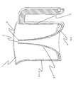
- FIG. 7 illustrates a perspective view of another embodiment of an integrated measuring cup and funnel system.
- the description may disclose several preferred embodiments of measuring cups integrated with funnels, as well as operation and/or component parts thereof. While the following description will be described in terms of measuring cups integrated with a funnel device systems and devices for clarity and to place the invention in context, it should be kept in mind that the teachings herein may have broad application to all types of systems, devices and applications.
- One embodiment of the invention provides a measuring cup and funnel system including a measuring cup and a funnel portion formed within the measuring cup.
- the measuring cup includes measurement indicators based on volume within an interior of the measuring cup considering displacement of the funnel portion.
- FIG. 1 illustrates a perspective view of a measuring cup 100 shown in the “measuring cup” upright position according to one embodiment of the invention.
- the measuring cup 100 includes a vessel rim portion 1 , a base inversion or funnel portion 3 , a plug 7 , measurement indicators 120 and a pouring spout 125 .
- the measuring cup 100 includes a handle 110 .
- the handle 110 includes a groove 115 for positioning a user's thumb for an ergonomical fit. In other embodiments, the handle is optional.
- the plug is placed in a narrow funnel opening for preventing liquid or other material (e.g., flour, sugar, etc.) from entering the funnel portion 3 when the measuring cup 100 is in an upright position.
- liquid or other material e.g., flour, sugar, etc.
- the measurement indicators 120 take into consideration the displaced volume that the funnel portion 3 causes to the interior of the measuring cup 100 . Since the total volume within the measuring cup 100 is equal to the volume of the measuring cup (without the funnel portion) minus the displacement volume of the funnel portion 3 , the measurement indicators are offset from where standard measuring cup indicators would be placed.
- the measurement indicators 120 may be etched, inked, added via laser, painted, etc. In other examples, the measurement indicators may be raised (from the exterior of the measuring cup 100 ) or indented.
- the measurement indicators include written measurement levels (e.g., 1 ⁇ 4 cup, 1 ⁇ 2 cup, 3 ⁇ 4 cup, 1 cup, etc.). In other examples, the written measurement levels may be raised, indented or include Braille indicators for users with poor or loss of vision.
- FIG. 2 illustrates the measuring cup 100 shown in an upside-down or funnel position.
- the measuring cup 100 includes a bottom rim portion 11 , wide funnel end opening 4 .
- the plug 7 fits within an opening or void within the handle 110 . It should be noted that in other embodiments of the invention, the plug may be placed in other openings or voids, such as other portions of the handle or portions of the measuring cup 100 (see, e.g., FIG. 7 ).
- FIG. 3 illustrates the measuring cup 100 shown filled with a liquid in the upright position.
- FIG. 4 shows a cross-section, perspective view of the measuring cup 100 shown in the measuring cup or upright position.
- the measuring cup 100 includes the vessel rim portion 1 , vessel walls 2 , funnel or base inversion 3 , funnel wide opening end 4 , funnel narrow opening end 5 , and a funnel narrow rim portion 6 .
- the handle 110 has a same height as the height of the measuring cup 100 measured form the base/bottom rim portion 11 to the vessel rim portion 1 . In other embodiments of the invention, the handle has a height less than the height of the measuring cup.
- FIG. 5 shows a perspective view an embodiment of the invention shown with the funnel plug 7 placed into the funnel narrow opening end 5 .
- the measuring cup is formed via injection molding.
- the measuring cup 100 may be formed from extrusion, glass molding, etc.
- FIG. 6 shows a perspective view of the measuring cup 100 shown in the funnel or upside-down position.
- the funnel plug 7 is stored in a void/opening 615 in the handle 110 .
- the measuring cup 100 includes a measuring vessel that has a bottom surface and walls 2 that allow for the containment of liquids and solid material.
- the portion of the bottom surface that inverts upward into the containment region and narrows toward the height of the vessel rim portion 1 .
- the uppermost portion of this base inversion of funnel portion 3 comprises a funnel narrow opening 5 and funnel narrow rim 6 , such that when the measuring cup 100 is in the funnel position, the formed funnel may be used for funneling material or liquid into another container.
- liquid may be poured into the funnel wide opening end 4 , which will flow through the funnel portion 3 and out of the funnel narrow opening end 5 .
- the funnel plug 7 placed within the funnel narrow opening end 5 prevents any liquid from entering the funnel narrow opening end 5 and flowing through the funnel portion 3 , for preventing spills.
- the funnel plug 7 may be removed when using the invention as a funnel in the funnel position.
- the funnel plug 7 may be stored within the handle as shown in FIG. 6 .
- the measuring cup 100 may be made of one or more of: injection-molded plastic, glass, polycarbonate, reinforced polypropylene, polypropylene, high-density polyethylene, nylon material, hardened plastic, polymer, rubber, composite material, metal or metal alloy, etc., or other similar materials.
- the measuring cup 100 may be clear or translucent. In other examples, the measuring cup 100 may be opaque and include internal measurement indicators (not shown).
- the measuring cup 100 placed in the funnel or upside-down position provides an additional benefit of being placed over another container that material or liquid is being funneled into. This prevents spilling and also provides additional control when funneling. Additionally, the funnel may be placed over another container for hands-free funneling. The handle 110 also provides added control when using the measuring cup 100 as a funnel.
- the measurement cup 100 provides a combined measuring cup/funnel and doesn't take up the additional space that separate funnel and measuring cups would otherwise need. With an easy flip and fill design, the measuring cup 100 provides multi-purposes and ease of use.
- FIG. 7 illustrates a perspective view of another embodiment of the invention shown in an upright state with the funnel inverted.
Abstract
Description
Claims (16)
Priority Applications (1)
| Application Number | Priority Date | Filing Date | Title |
|---|---|---|---|
| US13/531,331 US8813563B2 (en) | 2011-06-22 | 2012-06-22 | Measuring cup |
Applications Claiming Priority (2)
| Application Number | Priority Date | Filing Date | Title |
|---|---|---|---|
| US201161500015P | 2011-06-22 | 2011-06-22 | |
| US13/531,331 US8813563B2 (en) | 2011-06-22 | 2012-06-22 | Measuring cup |
Publications (2)
| Publication Number | Publication Date |
|---|---|
| US20120324997A1 US20120324997A1 (en) | 2012-12-27 |
| US8813563B2 true US8813563B2 (en) | 2014-08-26 |
Family
ID=47360543
Family Applications (1)
| Application Number | Title | Priority Date | Filing Date |
|---|---|---|---|
| US13/531,331 Expired - Fee Related US8813563B2 (en) | 2011-06-22 | 2012-06-22 | Measuring cup |
Country Status (1)
| Country | Link |
|---|---|
| US (1) | US8813563B2 (en) |
Cited By (3)
| Publication number | Priority date | Publication date | Assignee | Title |
|---|---|---|---|---|
| US20150122015A1 (en) * | 2012-06-14 | 2015-05-07 | Koninklijke Philips N.V. | Capacitive level sensor |
| US20190257512A1 (en) * | 2018-02-21 | 2019-08-22 | Richard Dunphy | Torch Refilling Assembly |
| USD890575S1 (en) * | 2018-10-30 | 2020-07-21 | Medline Industries, Inc. | Container |
Families Citing this family (4)
| Publication number | Priority date | Publication date | Assignee | Title |
|---|---|---|---|---|
| EP2952470A1 (en) * | 2014-06-06 | 2015-12-09 | Rotho Kunststoff AG | Funnel with measuring cup |
| US9828140B1 (en) * | 2014-07-23 | 2017-11-28 | Gloria Molina | Container with inverted hook-shaped handle |
| DE202014105352U1 (en) * | 2014-11-07 | 2015-01-08 | De'longhi Braun Household Gmbh | Combined measuring cup for mixing containers |
| US20170360226A1 (en) * | 2016-06-21 | 2017-12-21 | Numan Zeidan | Cup collar |
Citations (7)
| Publication number | Priority date | Publication date | Assignee | Title |
|---|---|---|---|---|
| US2736469A (en) * | 1952-04-15 | 1956-02-28 | Ashton K Stone | Sealing and pouring closures |
| US4416381A (en) * | 1981-11-27 | 1983-11-22 | Swartwout Everett W | Bottle cap with integral measuring cup and bottle closure |
| US4981144A (en) * | 1985-03-18 | 1991-01-01 | Henry A. Carels, Jr. | Urine separation and collection device |
| US5551606A (en) * | 1994-07-14 | 1996-09-03 | Rai; Charn | Dispenser |
| US5662249A (en) * | 1995-09-07 | 1997-09-02 | Grosse; Allison | All in one measure/funnel/pour/mix/shake container |
| US8100008B2 (en) * | 2008-02-01 | 2012-01-24 | Mentesh William M | Measuring cap |
| US20120097556A1 (en) * | 2010-10-25 | 2012-04-26 | Jonathon Derek Gascoine | Funnel-shaped container with capped ends |
-
2012
- 2012-06-22 US US13/531,331 patent/US8813563B2/en not_active Expired - Fee Related
Patent Citations (7)
| Publication number | Priority date | Publication date | Assignee | Title |
|---|---|---|---|---|
| US2736469A (en) * | 1952-04-15 | 1956-02-28 | Ashton K Stone | Sealing and pouring closures |
| US4416381A (en) * | 1981-11-27 | 1983-11-22 | Swartwout Everett W | Bottle cap with integral measuring cup and bottle closure |
| US4981144A (en) * | 1985-03-18 | 1991-01-01 | Henry A. Carels, Jr. | Urine separation and collection device |
| US5551606A (en) * | 1994-07-14 | 1996-09-03 | Rai; Charn | Dispenser |
| US5662249A (en) * | 1995-09-07 | 1997-09-02 | Grosse; Allison | All in one measure/funnel/pour/mix/shake container |
| US8100008B2 (en) * | 2008-02-01 | 2012-01-24 | Mentesh William M | Measuring cap |
| US20120097556A1 (en) * | 2010-10-25 | 2012-04-26 | Jonathon Derek Gascoine | Funnel-shaped container with capped ends |
Cited By (4)
| Publication number | Priority date | Publication date | Assignee | Title |
|---|---|---|---|---|
| US20150122015A1 (en) * | 2012-06-14 | 2015-05-07 | Koninklijke Philips N.V. | Capacitive level sensor |
| US20190257512A1 (en) * | 2018-02-21 | 2019-08-22 | Richard Dunphy | Torch Refilling Assembly |
| US10539319B2 (en) * | 2018-02-21 | 2020-01-21 | Richard Dunphy | Torch refilling assembly |
| USD890575S1 (en) * | 2018-10-30 | 2020-07-21 | Medline Industries, Inc. | Container |
Also Published As
| Publication number | Publication date |
|---|---|
| US20120324997A1 (en) | 2012-12-27 |
Similar Documents
| Publication | Publication Date | Title |
|---|---|---|
| US8813563B2 (en) | Measuring cup | |
| US7845524B2 (en) | Apparatus and method of dispensing fluid | |
| US20130008919A1 (en) | Apparatus and methods for dispensing fluid | |
| US6877639B1 (en) | Liquid measuring and dispensing device | |
| JP5199195B2 (en) | Weighing container | |
| US20090302063A1 (en) | Dosing Device for a Fluid | |
| ZA200708155B (en) | Liquid dispensing apparatus and device | |
| JP2016011129A (en) | Cap for container with check valve | |
| US20150223624A1 (en) | Combination dosing chaser device | |
| US20130193169A1 (en) | Container capable of pouring out liquid in fixed quantity | |
| EP1652462A3 (en) | Cleaning chemical dispensing system | |
| US3224652A (en) | Metering liquid dispenser | |
| US11623781B2 (en) | Container with corrugations | |
| US4214679A (en) | Measured quantity dispenser | |
| US4116371A (en) | Metering device and method | |
| AU2002346879B2 (en) | Container for storing and pouring liquids | |
| US5071039A (en) | Viscous liquid dispensing container | |
| US11365043B2 (en) | Fluid dispensing system | |
| JP2010215250A (en) | Liquid-measuring and discharging container | |
| KR101271169B1 (en) | Container for liquid medicine | |
| JP2011131895A (en) | Measuring container | |
| JP5537838B2 (en) | Weighing cap | |
| JP6295174B2 (en) | Metering dispenser | |
| KR20050067357A (en) | A stopper for discharging fixed quantity of liquid | |
| CN205801886U (en) | A kind of medicinal liquor barrel |
Legal Events
| Date | Code | Title | Description |
|---|---|---|---|
| AS | Assignment |
Owner name: EVRIHOLDER PRODUCTS, LLC, CALIFORNIA Free format text: ASSIGNMENT OF ASSIGNORS INTEREST;ASSIGNORS:THARP, BRUCE MITCHELL;THARP, STEPHANIE M.;REEL/FRAME:028430/0517 Effective date: 20120622 |
|
| AS | Assignment |
Owner name: BANK OF MONTREAL, AS ADMINISTRATIVE AGENT, ILLINOI Free format text: SECURITY AGREEMENT;ASSIGNOR:EVRIHOLDER PRODUCTS, LLC;REEL/FRAME:030503/0381 Effective date: 20130509 |
|
| FEPP | Fee payment procedure |
Free format text: MAINTENANCE FEE REMINDER MAILED (ORIGINAL EVENT CODE: REM.) |
|
| LAPS | Lapse for failure to pay maintenance fees |
Free format text: PATENT EXPIRED FOR FAILURE TO PAY MAINTENANCE FEES (ORIGINAL EVENT CODE: EXP.); ENTITY STATUS OF PATENT OWNER: SMALL ENTITY |
|
| PRDP | Patent reinstated due to the acceptance of a late maintenance fee |
Effective date: 20181010 |
|
| FEPP | Fee payment procedure |
Free format text: PETITION RELATED TO MAINTENANCE FEES FILED (ORIGINAL EVENT CODE: PMFP); ENTITY STATUS OF PATENT OWNER: SMALL ENTITY Free format text: PETITION RELATED TO MAINTENANCE FEES GRANTED (ORIGINAL EVENT CODE: PMFG); ENTITY STATUS OF PATENT OWNER: SMALL ENTITY Free format text: SURCHARGE, PETITION TO ACCEPT PYMT AFTER EXP, UNINTENTIONAL. (ORIGINAL EVENT CODE: M2558); ENTITY STATUS OF PATENT OWNER: SMALL ENTITY |
|
| MAFP | Maintenance fee payment |
Free format text: PAYMENT OF MAINTENANCE FEE, 4TH YR, SMALL ENTITY (ORIGINAL EVENT CODE: M2551); ENTITY STATUS OF PATENT OWNER: SMALL ENTITY Year of fee payment: 4 |
|
| STCF | Information on status: patent grant |
Free format text: PATENTED CASE |
|
| AS | Assignment |
Owner name: TWIN BROOK CAPITAL PARTNERS, LLC, AS AGENT, ILLINO Free format text: SECURITY INTEREST;ASSIGNOR:EVRIHOLDER PRODUCTS, LLC;REEL/FRAME:047245/0498 Effective date: 20181016 |
|
| AS | Assignment |
Owner name: EVRIHOLDER PRODUCTS, LLC, CALIFORNIA Free format text: RELEASE BY SECURED PARTY;ASSIGNOR:BANK OF MONTREAL, AS ADMINISTRATIVE AGENT;REEL/FRAME:047220/0576 Effective date: 20181016 |
|
| FP | Lapsed due to failure to pay maintenance fee |
Effective date: 20180826 |
|
| AS | Assignment |
Owner name: JPMORGAN CHASE BANK, N.A., AS ADMINISTRATIVE AGENT, ILLINOIS Free format text: SECURITY INTEREST;ASSIGNOR:EVRIHOLDER PRODUCTS, LLC;REEL/FRAME:055952/0610 Effective date: 20210416 |
|
| AS | Assignment |
Owner name: EVRIHOLDER PRODUCTS, LLC, CALIFORNIA Free format text: RELEASE BY SECURED PARTY;ASSIGNOR:TWIN BROOK CAPITAL PARTNERS, LLC, AS AGENT;REEL/FRAME:055983/0058 Effective date: 20210419 |
|
| FEPP | Fee payment procedure |
Free format text: MAINTENANCE FEE REMINDER MAILED (ORIGINAL EVENT CODE: REM.); ENTITY STATUS OF PATENT OWNER: SMALL ENTITY |
|
| LAPS | Lapse for failure to pay maintenance fees |
Free format text: PATENT EXPIRED FOR FAILURE TO PAY MAINTENANCE FEES (ORIGINAL EVENT CODE: EXP.); ENTITY STATUS OF PATENT OWNER: SMALL ENTITY |
|
| STCH | Information on status: patent discontinuation |
Free format text: PATENT EXPIRED DUE TO NONPAYMENT OF MAINTENANCE FEES UNDER 37 CFR 1.362 |
|
| FP | Lapsed due to failure to pay maintenance fee |
Effective date: 20220826 |
|
| AS | Assignment |
Owner name: EVRIHOLDER PRODUCTS, LLC, CALIFORNIA Free format text: RELEASE BY SECURED PARTY;ASSIGNOR:JPMORGAN CHASE BANK, N.A., AS ADMINISTRATIVE AGENT;REEL/FRAME:062635/0064 Effective date: 20230123 |
|
| AS | Assignment |
Owner name: EVRIHOLDER PRODUCTS, LLC, CALIFORNIA Free format text: RELEASE BY SECURED PARTY;ASSIGNOR:JPMORGAN CHASE BANK, N.A., AS ADMINISTRATIVE AGENT;REEL/FRAME:063753/0980 Effective date: 20230123 |