US7845524B2 - Apparatus and method of dispensing fluid - Google Patents
Apparatus and method of dispensing fluid Download PDFInfo
- Publication number
- US7845524B2 US7845524B2 US11/199,587 US19958705A US7845524B2 US 7845524 B2 US7845524 B2 US 7845524B2 US 19958705 A US19958705 A US 19958705A US 7845524 B2 US7845524 B2 US 7845524B2
- Authority
- US
- United States
- Prior art keywords
- fluid
- pour
- chamber
- indicating
- spout
- Prior art date
- Legal status (The legal status is an assumption and is not a legal conclusion. Google has not performed a legal analysis and makes no representation as to the accuracy of the status listed.)
- Expired - Fee Related, expires
Links
Images


Classifications
-
- G—PHYSICS
- G01—MEASURING; TESTING
- G01F—MEASURING VOLUME, VOLUME FLOW, MASS FLOW OR LIQUID LEVEL; METERING BY VOLUME
- G01F11/00—Apparatus requiring external operation adapted at each repeated and identical operation to measure and separate a predetermined volume of fluid or fluent solid material from a supply or container, without regard to weight, and to deliver it
- G01F11/10—Apparatus requiring external operation adapted at each repeated and identical operation to measure and separate a predetermined volume of fluid or fluent solid material from a supply or container, without regard to weight, and to deliver it with measuring chambers moved during operation
- G01F11/26—Apparatus requiring external operation adapted at each repeated and identical operation to measure and separate a predetermined volume of fluid or fluent solid material from a supply or container, without regard to weight, and to deliver it with measuring chambers moved during operation wherein the measuring chamber is filled and emptied by tilting or inverting the supply vessel, e.g. bottle-emptying apparatus
- G01F11/262—Apparatus requiring external operation adapted at each repeated and identical operation to measure and separate a predetermined volume of fluid or fluent solid material from a supply or container, without regard to weight, and to deliver it with measuring chambers moved during operation wherein the measuring chamber is filled and emptied by tilting or inverting the supply vessel, e.g. bottle-emptying apparatus for liquid or semi-liquid
-
- G—PHYSICS
- G01—MEASURING; TESTING
- G01F—MEASURING VOLUME, VOLUME FLOW, MASS FLOW OR LIQUID LEVEL; METERING BY VOLUME
- G01F11/00—Apparatus requiring external operation adapted at each repeated and identical operation to measure and separate a predetermined volume of fluid or fluent solid material from a supply or container, without regard to weight, and to deliver it
- G01F11/10—Apparatus requiring external operation adapted at each repeated and identical operation to measure and separate a predetermined volume of fluid or fluent solid material from a supply or container, without regard to weight, and to deliver it with measuring chambers moved during operation
- G01F11/26—Apparatus requiring external operation adapted at each repeated and identical operation to measure and separate a predetermined volume of fluid or fluent solid material from a supply or container, without regard to weight, and to deliver it with measuring chambers moved during operation wherein the measuring chamber is filled and emptied by tilting or inverting the supply vessel, e.g. bottle-emptying apparatus
Definitions
- the invention generally relates to fluid and other dispensers and, more particularly, the invention relates to determining volumes of fluid and other materials dispensed from fluid dispensers.
- liquid laundry detergent typically is packaged in a container having a removable cap. Accordingly, when washing a load of laundry, a person may remove the cap from the container and pour a measured amount of detergent into their washing machine.
- an apparatus for dispensing a flowable substance has a first housing with an indicating apparatus and a pour chamber.
- the indicating apparatus includes an indicating chamber with an indicating inlet for receiving fluid.
- the indicating apparatus also has indicia identifying amounts of fluid flowing through the pour chamber.
- the pour chamber has a pour inlet for receiving fluid, and an outlet in fluid communication with the pour inlet.
- the first housing additionally has a wall between the indicating chamber and the pour chamber.
- the indicia identifies amounts of fluid flowing through the outlet.
- the indicating chamber may include a substantially translucent or transparent wall having graduations that form at least part of the indicia.
- the apparatus also may have a second housing for containing fluid, where the first housing is removably couplable with the second housing.
- the first housing and second housing may be couplable by means of a threaded connection.
- the apparatus may have a number of other components, including one or more of 1) a flange extending about at least a portion of one or both the pour inlet and the indicating inlet, 2) a fluid guide extending inwardly of the pour inlet relative to the first housing, and 3) a fluid redirector between the pour inlet and an outlet chamber that extends to the outlet of the pour chamber.
- the first housing may be at least partially formed from a hydrophobic material having a vent formed therethrough. The vent illustratively may be formed in one of the indicating chamber and the pour chamber. In some embodiments, the indicating chamber is closed to the exterior of the first housing.
- a spout has a pour chamber with a pour inlet and a pour outlet, and an indicating chamber having an indicating inlet.
- the indicating chamber is closed to the exterior of the spout, while the indicating chamber has a substantially transparent or translucent wall with visual indicia.
- the pour inlet and the indicating inlet open to a common volume.
- a method of producing an apparatus for dispensing fluid forms 1) a spout having a indicating chamber with an indicating inlet for receiving fluid, and 2) a pour chamber within the spout.
- the pour chamber has a pour inlet for receiving fluid and a pour outlet in fluid communication with both the pour inlet and the exterior of the spout.
- the method also determines an approximate rate that the indicating chamber fills as a function of the rate that fluid flows from the pour outlet. Indicia then is added to the indicating chamber to identify amounts of fluid flowing from the pour outlet.
- a method of pouring a fluid from a container having a spout with a fluid outlet first tilts the container to at least one angle that causes fluid to enter the spout. Consequently, the fluid exits the spout through the fluid outlet.
- the method samples a portion of the fluid entering the spout.
- the portion of fluid being sampled has a volume that is related to the volume of fluid passing through the fluid outlet.
- the method causes the portion of fluid that was sampled to produce a visual indication of the approximate volume of fluid passing through the fluid outlet.
- the spout or portion of the container includes a plurality of fluid ports for receiving fluid contained by the container.
- the plurality of ports are in an area of the spout or portion of the container.
- the method may partially obstruct fluid flow around at least a portion of the fluid ports to concentrate fluid to a portion of the area around the ports after tilting.
- the method may partially obstruct fluid flow through at least one of the ports.
- a spout has a housing forming an inlet, an outlet, and a channel between the inlet and the outlet.
- the housing has a housing volume between the inlet and the outlet.
- the spout also has indicia adapted to show the approximate volume of fluid that passes through the outlet in real time.
- the indicia includes indicia identifying at least one volume that is greater than the housing volume between the inlet and the outlet.
- FIG. 1 schematically shows a perspective view of a fluid dispensing system incorporating illustrative embodiments of the invention.
- FIG. 2 schematically shows a perspective, partially cut away view of a spout shown in FIG. 1 and configured in accordance with illustrative embodiments of the invention.
- FIG. 3 schematically shows a fluid dispensing system of FIG. 1 while pouring fluid through its outlet.
- FIG. 4A shows a cross-sectional view of the fluid dispensing system shown in FIG. 1 in a rest position. This Figure is a cross-sectional view across an inlet to the indicating chamber.
- FIG. 4B also shows a cross-sectional view of the fluid dispensing system shown in FIG. 1 in a rest position. This Figure is a cross-sectional view across an inlet to the pour chamber.
- FIG. 5A shows the cross-sectional view of FIG. 4A while pouring fluid through its spout.
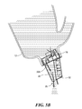
- FIG. 5B shows the cross-sectional view of FIG. 4B while pouring fluid through its spout.
- FIG. 6 schematically shows an exploded view of the spout shown in FIG. 2 .
- FIG. 7 schematically shows a bottom view of the spout shown in FIG. 2 with its covering lid removed.
- FIGS. 8A and 8B schematically show interior and exterior sides of a covering lid, which is part of the spout shown in FIG. 2 .
- a fluid dispensing spout identifies, in real time, the approximate cumulative amount of fluid passing through it during a single pour. For example, if it is part of a laundry detergent container, the spout may identify the approximate amount of detergent poured into a washing machine at a given time. Accordingly, a user does not need to use a measuring cup or other apparatus to ensure that the proper amount of detergent has been dispensed. To that end, the spout may be considered to sample a portion of fluid entering it, and identify substantially the total volume of fluid passing through its outlet as a function of the sampled fluid. Details of various embodiments are discussed below.
- FIG. 1 schematically shows a perspective view of a fluid dispensing system 10 incorporating illustrative embodiments of the invention. More specifically, the fluid dispensing system 10 shown in FIG. 1 includes a laundry detergent container 12 for containing laundry detergent, and a spout 14 that dynamically identifies, in real time, the cumulative amount of fluid passing through it during a single pour.
- the container 12 may be formed from injection molded or blow-molded plastic and have an integrated handle to facilitate use.
- the spout 14 may connect to the container 12 in a wide variety of ways.
- the spout 14 may be integrated into the neck 16 of the container 12 , or adhered to the container 12 by an adhesive or conventional ultrasonic welding process.
- the spout 14 may be removably connected to the container 12 .
- the spout 14 may have threads 18 (see FIG. 2 ) that screw into a mating portion of the container 12 .
- threads 18 see FIG. 2
- those skilled in the art should understand that a variety of conventional means may be used to removably connect the spout 14 to the container 12 .
- the spout 14 may connect with the container 12 at any other reasonable location.
- the spout 14 may be connected to the side of the container 12 , or even to what appears to be the bottom of the container 12 (e.g., via a specially molded container 12 that permits the nozzle to be mounted in such a manner).
- Valving devices (not shown) also may be used to more carefully control fluid flow.
- a laundry detergent container 12 laundry detergent, and a laundry detergent system is for illustrative purposes only and not intended to limit the scope of all embodiments of the invention.
- various embodiments can be implemented with a wide variety of containers containing many different types of fluids.
- discussion of liquids, such as liquid laundry detergent also is for illustrative purposes and not intended to limit the scope of all embodiments of the invention.
- some embodiments may dynamically measure volumes of motor oil flowing through the spout 14 .
- fluids flowing through the spout 14 may include liquids, such as liquid laundry detergent, or powders, such as laundry detergent or bleach in powder form.
- FIG. 2 shows a partially cut away, perspective view of the spout 14 shown in FIG. 1 .
- the spout 14 has a bottom portion 20 that screws onto the neck 16 of the container 12 , a main body 22 for both identifying fluid volumes and permitting fluid to flow therethrough, and a top portion 24 that forms a fluid outlet 26 . All portions illustratively are formed from plastic by conventional injection molding processes.
- the top portion 24 also includes a cap 28 formed as living hinge that provides a snap-fit closure for the fluid outlet 26 . Accordingly, prior to pouring fluid through the spout 14 , a user pivots the cap 28 rearwardly to open the fluid outlet 26 . A corresponding manner, after pouring fluid through the spout 14 , the user may pivot the cap 28 back toward the fluid outlet 26 to prevent inadvertent fluid leakage.
- the main body 22 respectively has a pour chamber 30 that channels fluid to the outlet 26 , and an indicating chamber 32 for identifying cumulative amounts of fluid passing through the outlet 26 during a single pour.
- the indicating chamber 32 has an indicating inlet 34 at its bottom end for receiving a sample amount of fluid, and a closed opposite end 36 . Accordingly, the indicating inlet 34 is the only port for permitting fluid in or out of the indicating chamber 32 . It thus acts as a fluid outlet in certain instances (e.g., when turned upright after pouring fluid through the pour chamber 30 ).
- the indicating chamber 32 also has a transparent or translucent side wall 38 with visual indicia 40 identifying the approximate volume of fluid flowing through the fluid outlet 26 .
- the indicia 40 simply are horizontal graduations with optional identifying symbols.
- the indicia 40 nevertheless can include a number of other means, including different visual markings, movable parts and/or audible signals. Details of illustrative movable parts are shown in copending U.S. patent application Ser. No. 11/199,578, filed Aug. 8, 2005 and entitled, “APPARATUS AND METHOD OF DISPENSING FLUID.
- Audible signals can be implemented in a number of manners.
- a microchip (not shown) may be configured both to detect fluid volumes and emit a beep for every ounce of fluid it detects. Such a microchip may be positioned in the indicating chamber 32 . In some embodiments, however, the indicating chamber 32 may be eliminated by positioning the microchip within the pour chamber 30 .
- the venting could be tuned to provide audible signals indicating fluid volumes being poured.
- the bottom graduation i.e., the graduation nearest the closed end 36 of the indicating chamber 32
- the next graduation may indicate about a half cup of fluid
- the third graduation may indicate about three quarters of a cup of fluid
- the final graduation i.e., nearest the indicating inlet 34
- fluid flow may be controlled to provide graduations identifying any practical, desired level.
- the sizes of the pour inlet 30 A and the indicating inlet 34 , as well as the interior geometry of the chambers may be changed to increase or decrease fluid flow.
- the graduations discussed above therefore are exemplary and not intended to limit various aspects of the invention.
- the indicating chamber 32 also has vent holes 42 to facilitate fluid flow into and out of its interior.
- the vent holes 42 are substantially smaller than the indicating inlet 34 .
- the material forming the vent holes 42 illustratively has hydrophobic qualities that, together with the small size of the vent holes 42 , mitigate the likelihood of fluid flowing therethrough.
- the size of the vent holes 42 nevertheless are coordinated with the size of the indicating inlet 34 , housing material, and anticipated flow properties of the fluid (e.g., surface tension and viscosity) to ensure appropriate fluid flow into and from the indicating chamber 32 .
- the spout 14 has additional vents, discussed below, which have similar properties relative to other discussed ports.
- FIGS. 4A and 4B schematically show cross-sectional views of the system 10 shown in FIG. 1 when upright (i.e., not pouring fluid).
- FIG. 4A shows a cross-sectional view through the indicating inlet 34
- FIG. 4B shows a cross-sectional view through a fluid path leading to the pour inlet 30 A.
- FIGS. 4A and 4B also have flow arrows showing the direction that fluid should flow when the system 10 is tilted for pouring fluid.
- the flow arrows in FIG. 4A show the path that fluid should take into the indicating chamber 32
- the flow arrows in FIG. 4B show the path that fluid should take into the pour chamber 30 .
- FIGS. 4A and 4B clearly show a number of the internal components, including the pour chamber 30 , indicating chamber 32 , and a dividing wall 44 between the two chambers. Various of these details are discussed below with regard to FIGS. 6 , 7 , 8 A, and 8 B (discussed below).
- FIGS. 5A and 5B respectively show the views of FIGS. 4A and 4B while pouring fluid (corresponding to FIG. 3 ). As shown in FIGS. 5A and 5B , fluid follows the paths delineated by the flow arrows of FIGS. 4A and 4B .
- the spout 14 may be produced in accordance with conventional processes.
- the spout 14 may be considered to be formed by coupled first, second, and third separately moldable pieces.
- the first piece 46 has the indicating chamber 32 and cap 28
- the second piece 48 has the pour chamber 30 extending upwardly from a base portion 50 , and threads 18 extending downwardly from the base portion 50 .
- the third piece 52 has a flow control apparatus 54 , which comprises a vented lid 56 and a fluid handler 58 for directing fluid within the spout 14 .
- the three pieces 46 , 48 , and 52 may be coupled in a conventional manner, such as by one or more of an adhesive or ultrasonic welding process. In some embodiments, however, rather than be a part of the second piece, the threads 18 may be formed as part of the third piece 52 .
- FIGS. 7 , 8 A, and 8 B show additional details of the third piece 52 .
- FIG. 7 shows a bottom view of the fluid handler 58 uncoupled from the vented lid 56 (shown in FIGS. 8A and 8B ).
- This embodiment shown in FIG. 7 also includes the threads 18 .
- the fluid handler 58 includes a number of integral components that cooperate with the vented lid 56 to direct fluid either to the indicating chamber 32 or the pour chamber 30 in a controlled manner.
- the fluid handler 58 includes a flat surface 60 forming an inlet channel 62 leading to the indicating chamber 32 , and the above discussed pour inlet 30 A.
- the fluid handler 58 also includes a fluid redirector 64 extending from the flat surface 60 .
- the fluid handler 58 illustratively is a large diameter, curved, concave wall from the perspective of the pour inlet 30 A. Accordingly, when the system 10 is in a pouring mode, the convex surface of the fluid redirector 64 reduces the speed at which a fluid enters the pour inlet 30 A. Consequently, fluid flow through the spout 14 should be smoother and more controlled.
- the fluid handler 58 also includes vent holes 42 for the indicating chamber 32 and the pour chamber 30 , as well as positioners 66 that facilitate attachment of the vented lid 56 to the fluid handler 58 .
- the vented lid 56 therefore has indents 68 along its rim (see FIGS. 8A and 8B , discussed below) corresponding to the locations of the positioners 66 .
- FIGS. 8A and 8B respectively show exterior and interior views of the vented lid 56 .
- the interior side of the vented lid 56 and fluid handler 58 are considered to form an interior chamber 70 (see FIG. 4A ) that leads to the pour inlet 30 A of the pour chamber 30 .
- the vented lid 56 may be considered to have a base 73 with five aligned fluid openings 72 , and a vent hole 42 for venting the interior chamber 70 .
- the center fluid opening (shown as 72 A) is in intimate contact with and leads directly to the inlet channel 62 of the fluid handler 58 (i.e., leading to the indicating chamber 32 ), while the other openings generally lead to the interior chamber 70 .
- fluid flows from the exterior side of the vented lid 56 , through the five fluid openings 72 , and into either the indicating chamber 32 or the interior chamber 70 . Fluid in the interior chamber 70 ultimately leads to the pour inlet 30 A.
- the vented lid 56 also includes a flange 74 extending partially about the five fluid openings 72 .
- the flange 74 extends approximately around three sides of the fluid openings 72 .
- the flange 74 has a number of benefits, including having the effect of pooling fluid in the area of the fluid openings 72 . By pooling fluid in this manner, fluid should flow through the outlet 26 in a more continuous manner.
- FIG. 8B shows the interior side of the vented lid 56 , which includes a pair of fluid guides 76 that extend inwardly of the base 73 .
- each fluid guide 76 has a concave interior surface that redirects incoming fluid from the fluid openings 72 into the interior chamber 70 in a direction that is not substantially normal to the surface of the base 73 .
- fluid exiting the terminal end of one of the fluid guides 76 should not be traveling in a direction that is normal to the base 73 .
- the fluid guides 76 should have the effect of decreasing fluid flow rates, thus providing a smoother and more constant flow of fluid through the spout 14 in many anticipated instances.
- the size, number, and geometry of the various discussed vented lid components are carefully controlled to ensure prespecified flow rates through the spout 14 .
- the vented lid 56 could have smaller fluid openings 72 or fewer fluid openings 72 to provide slower fluid flow rates through the spout 14 .
- discussion of specific geometries and numbers, such as five substantially rectangular fluid openings 72 , or the geometry of the flange 74 is for illustrative purposes only and not intended to limit all embodiments of the invention.
- a user may tilt the container 12 to an angle that causes fluid to pass through the spout 14 (see FIG. 3 ).
- the user may continue to pour the fluid until the indicating chamber 32 shows that a desired amount of fluid has been dispensed. At that point, the user may orient the system 10 in an upright manner (see FIG. 1 ) for storage. The user therefore does not need additional cups to measure the fluid.
- the user also does not need to remove the spout 14 from the container 12 . Instead, the user simply pours fluid in one step.
- the indicating chamber 32 may be considered to “sample” a portion of fluid flowing into the spout 14 . Because of the geometry and makeup of the spout 14 , this portion of fluid should be substantially proportional to the amount of fluid flowing through the spout outlet 26 . This portion of fluid entering the spout 14 thus cooperates with the visual indicia 40 to show approximate fluid volumes the system 10 dispenses. Moreover, different spout geometries can be used for different types of fluids having different flow characteristics. Empirical testing should suffice to pre-determine the proportion of sampled fluid in the indicating chamber 32 .
- fluid readings should be considered an approximation and not necessarily an exact amount. For example, a reading of 0.5 cups could indicate that the spout 14 dispensed 10% more or 10% less than 0.5 cups of fluid. Testing has determined that fluid readings often are less accurate when the container 12 is almost empty or completely full. In controlled laboratory conditions, accuracy is enhanced, therefore mitigating the error factor. It nevertheless is anticipated that during use, human error will contribute to the error factor.
Abstract
Description
Claims (38)
Priority Applications (1)
| Application Number | Priority Date | Filing Date | Title |
|---|---|---|---|
| US11/199,587 US7845524B2 (en) | 2004-11-02 | 2005-08-08 | Apparatus and method of dispensing fluid |
Applications Claiming Priority (2)
| Application Number | Priority Date | Filing Date | Title |
|---|---|---|---|
| US62386704P | 2004-11-02 | 2004-11-02 | |
| US11/199,587 US7845524B2 (en) | 2004-11-02 | 2005-08-08 | Apparatus and method of dispensing fluid |
Publications (2)
| Publication Number | Publication Date |
|---|---|
| US20060091153A1 US20060091153A1 (en) | 2006-05-04 |
| US7845524B2 true US7845524B2 (en) | 2010-12-07 |
Family
ID=35429481
Family Applications (2)
| Application Number | Title | Priority Date | Filing Date |
|---|---|---|---|
| US11/199,587 Expired - Fee Related US7845524B2 (en) | 2004-11-02 | 2005-08-08 | Apparatus and method of dispensing fluid |
| US11/199,578 Abandoned US20060091152A1 (en) | 2004-11-02 | 2005-08-08 | Apparatus and method of dispensing fluid |
Family Applications After (1)
| Application Number | Title | Priority Date | Filing Date |
|---|---|---|---|
| US11/199,578 Abandoned US20060091152A1 (en) | 2004-11-02 | 2005-08-08 | Apparatus and method of dispensing fluid |
Country Status (5)
| Country | Link |
|---|---|
| US (2) | US7845524B2 (en) |
| EP (1) | EP1817555A1 (en) |
| CA (1) | CA2585960C (en) |
| MX (1) | MX2007005272A (en) |
| WO (1) | WO2006049668A1 (en) |
Cited By (11)
| Publication number | Priority date | Publication date | Assignee | Title |
|---|---|---|---|---|
| US8424723B2 (en) | 2006-07-07 | 2013-04-23 | Fair Oaks Farms Brands, Inc. | Liquid food dispenser system and method |
| WO2013176924A1 (en) | 2012-05-22 | 2013-11-28 | The Procter & Gamble Company | Pour assist device |
| US9739272B2 (en) | 2012-11-29 | 2017-08-22 | Fair Oaks Farms Brands, Llc | Liquid product dispensing system and method |
| US10327599B2 (en) | 2017-04-26 | 2019-06-25 | The Procter & Gamble Company | Apparatus and process for dispensing a measured quantity of liquid |
| US10336514B1 (en) * | 2018-06-18 | 2019-07-02 | The Procter & Gamble Company | Angled spout associated with a timer for dispensing a controlled quantity of liquid composition |
| US10351319B1 (en) * | 2018-06-18 | 2019-07-16 | The Procter & Gamble Company | Angled spout associated with a timer for dispensing a controlled quantity of liquid composition |
| US20200025599A1 (en) * | 2017-02-13 | 2020-01-23 | Silgan Dispensing Systems Corporation | Dosing timer and dispensers using the same |
| US10698368B2 (en) | 2017-09-06 | 2020-06-30 | The Procter & Gamble Company | Apparatus and process for dispensing a measured quantity of liquid product |
| US10894650B1 (en) * | 2019-06-28 | 2021-01-19 | L'oreal | Dispensing assemblies for flexible packages |
| US11054294B1 (en) * | 2020-05-29 | 2021-07-06 | Silgan Dispensing Systems Corporation | Dosing timer and dispensers using the same |
| US11099044B1 (en) * | 2020-05-29 | 2021-08-24 | Silgan Dispensing Systems Corporation | Dosing timer and dispensers using the same |
Families Citing this family (12)
| Publication number | Priority date | Publication date | Assignee | Title |
|---|---|---|---|---|
| WO2010068633A1 (en) * | 2008-12-12 | 2010-06-17 | Graham Packaging Company, L.P. | One piece unit dose liquid dispensing closure |
| US20100230405A1 (en) * | 2009-03-11 | 2010-09-16 | Nuvision Bioplastics, Llc | Biodegradable Resin Composition Utilized in the Manufacture of Biodegradable Containers, Biodegradable Containers, and Method of Manufacture |
| CN102459011B (en) * | 2009-06-11 | 2017-05-10 | J·M·斯马克公司 | Dispensing closure |
| EP2270123A1 (en) * | 2009-06-30 | 2011-01-05 | The Procter and Gamble Company | Packaged particulate bleaching compositions |
| GB2512800B (en) * | 2012-02-14 | 2018-02-21 | Westrock Slatersville Llc | One-piece molded auto-refill single dose dispenser |
| JP5955587B2 (en) * | 2012-02-28 | 2016-07-20 | 花王株式会社 | Metering cap |
| US9494456B2 (en) | 2014-05-15 | 2016-11-15 | Quaker Oats Company | Dry product dosage dispenser with multiple storage compartments and method for producing same |
| US9585503B2 (en) | 2014-05-15 | 2017-03-07 | The Quaker Oats Company | Dry product dosage dispenser and method for producing same |
| US9541440B2 (en) * | 2014-10-21 | 2017-01-10 | The Procter & Gamble Company | Dosing cup for a detergent composition |
| US10598535B1 (en) * | 2016-05-26 | 2020-03-24 | Plastek Industries, Inc. | Dispenser and methods |
| KR101855440B1 (en) | 2017-06-08 | 2018-05-04 | 전연태 | Lid of a liquid container |
| KR200488752Y1 (en) | 2018-01-26 | 2019-03-14 | 애경산업(주) | A cap for discharging fixed quantity from liquid container |
Citations (26)
| Publication number | Priority date | Publication date | Assignee | Title |
|---|---|---|---|---|
| US1957962A (en) * | 1933-07-19 | 1934-05-08 | Lawrence H Hyatt | Liquid dispenser |
| US2507362A (en) * | 1945-08-13 | 1950-05-09 | Wilhelm Bernhard | Vent controlled liquid measuring means |
| US2883086A (en) * | 1955-12-12 | 1959-04-21 | American Machine & Metals | Liquid dispensing attachment for bottle, with means for automatically measuring a charge upon inversion of bottle |
| US3181729A (en) * | 1962-10-31 | 1965-05-04 | Milonas | Fluid meter device |
| US3235143A (en) * | 1965-03-10 | 1966-02-15 | Robert P Panish | Dispensing container |
| US3288335A (en) * | 1963-12-04 | 1966-11-29 | Stubbe Friedrich | Metering device for dispensing identical quantities of liquids from liquid containers |
| GB1160472A (en) | 1967-06-14 | 1969-08-06 | Pressed Steel Fisher Ltd | A Visual Fluid Flow Indicator. |
| US4151934A (en) * | 1976-11-02 | 1979-05-01 | Noriyoshi Saeki | Fixed volume discharge device |
| DE2851449A1 (en) | 1977-11-30 | 1979-05-31 | Desomed Ag | BOTTLE WITH DOSING CAP |
| US4183450A (en) * | 1976-10-06 | 1980-01-15 | Neil Hugh Downing | Metering device |
| US4436223A (en) * | 1981-02-03 | 1984-03-13 | Wilson Jerry L | Device for recording the dispensing of fluids |
| US4666065A (en) | 1986-06-30 | 1987-05-19 | The Procter & Gamble Company | Liquid measuring and pouring device |
| US4893732A (en) * | 1989-06-12 | 1990-01-16 | Container Mfg. Inc. | Exact volume dispensing container |
| EP0358391A1 (en) | 1988-09-05 | 1990-03-14 | Nomix-Chipman Limited | A device for measuring flow |
| US4941519A (en) * | 1988-08-19 | 1990-07-17 | American Sterilizer Company | Liquid feed system using a non-reusable container |
| US5044527A (en) | 1989-08-30 | 1991-09-03 | Hickerson Frederick R | Liquid dispensing system |
| US5054660A (en) * | 1990-01-02 | 1991-10-08 | Colgate-Palmolive Co. | Self-dosing measuring chamber and container |
| US5129561A (en) * | 1989-12-20 | 1992-07-14 | The Procter & Gamble Company | Metering device for liquids having a metering chamber, a collecting chamber, and a separating baffle to prevent inadvertent flow therebetween |
| US5143261A (en) * | 1989-12-20 | 1992-09-01 | The Procter & Gamble Company | Multi-compartment container for proportional dispensing of a plurality of liquids |
| US5186367A (en) | 1991-02-21 | 1993-02-16 | Hickerson Frederick R | Measuring device for dispensing predetermined quantities of a liquid |
| US5292039A (en) * | 1993-08-10 | 1994-03-08 | Neofitou John M | Liquid measuring dispenser |
| US5667106A (en) * | 1995-06-07 | 1997-09-16 | E. S. Robbins Corporation | Container cap with a measuring spout |
| US6068165A (en) * | 1998-09-02 | 2000-05-30 | Minihane; Denis A. | Premeasured dispensing bottle cap |
| US6276572B1 (en) | 2000-08-10 | 2001-08-21 | Sussex Technology Inc. | Measuring device with conical cap |
| WO2001079791A1 (en) | 2000-04-07 | 2001-10-25 | Sussex Technology, Inc. | Measuring device for dispensing predetermined liquid quantities |
| US6330960B1 (en) * | 1999-06-04 | 2001-12-18 | Mcneil-Ppc, Inc. | Squeeze dispenser |
-
2005
- 2005-08-08 CA CA2585960A patent/CA2585960C/en not_active Expired - Fee Related
- 2005-08-08 US US11/199,587 patent/US7845524B2/en not_active Expired - Fee Related
- 2005-08-08 US US11/199,578 patent/US20060091152A1/en not_active Abandoned
- 2005-08-08 MX MX2007005272A patent/MX2007005272A/en active IP Right Grant
- 2005-08-08 WO PCT/US2005/027998 patent/WO2006049668A1/en active Application Filing
- 2005-08-08 EP EP05784242A patent/EP1817555A1/en not_active Withdrawn
Patent Citations (27)
| Publication number | Priority date | Publication date | Assignee | Title |
|---|---|---|---|---|
| US1957962A (en) * | 1933-07-19 | 1934-05-08 | Lawrence H Hyatt | Liquid dispenser |
| US2507362A (en) * | 1945-08-13 | 1950-05-09 | Wilhelm Bernhard | Vent controlled liquid measuring means |
| US2883086A (en) * | 1955-12-12 | 1959-04-21 | American Machine & Metals | Liquid dispensing attachment for bottle, with means for automatically measuring a charge upon inversion of bottle |
| US3181729A (en) * | 1962-10-31 | 1965-05-04 | Milonas | Fluid meter device |
| US3288335A (en) * | 1963-12-04 | 1966-11-29 | Stubbe Friedrich | Metering device for dispensing identical quantities of liquids from liquid containers |
| US3235143A (en) * | 1965-03-10 | 1966-02-15 | Robert P Panish | Dispensing container |
| GB1160472A (en) | 1967-06-14 | 1969-08-06 | Pressed Steel Fisher Ltd | A Visual Fluid Flow Indicator. |
| US4183450A (en) * | 1976-10-06 | 1980-01-15 | Neil Hugh Downing | Metering device |
| US4151934A (en) * | 1976-11-02 | 1979-05-01 | Noriyoshi Saeki | Fixed volume discharge device |
| DE2851449A1 (en) | 1977-11-30 | 1979-05-31 | Desomed Ag | BOTTLE WITH DOSING CAP |
| US4436223A (en) * | 1981-02-03 | 1984-03-13 | Wilson Jerry L | Device for recording the dispensing of fluids |
| US4666065A (en) | 1986-06-30 | 1987-05-19 | The Procter & Gamble Company | Liquid measuring and pouring device |
| US4941519A (en) * | 1988-08-19 | 1990-07-17 | American Sterilizer Company | Liquid feed system using a non-reusable container |
| EP0358391A1 (en) | 1988-09-05 | 1990-03-14 | Nomix-Chipman Limited | A device for measuring flow |
| US4893732A (en) * | 1989-06-12 | 1990-01-16 | Container Mfg. Inc. | Exact volume dispensing container |
| US5044527A (en) | 1989-08-30 | 1991-09-03 | Hickerson Frederick R | Liquid dispensing system |
| US5129561A (en) * | 1989-12-20 | 1992-07-14 | The Procter & Gamble Company | Metering device for liquids having a metering chamber, a collecting chamber, and a separating baffle to prevent inadvertent flow therebetween |
| US5143261A (en) * | 1989-12-20 | 1992-09-01 | The Procter & Gamble Company | Multi-compartment container for proportional dispensing of a plurality of liquids |
| US5054660A (en) * | 1990-01-02 | 1991-10-08 | Colgate-Palmolive Co. | Self-dosing measuring chamber and container |
| US5186367A (en) | 1991-02-21 | 1993-02-16 | Hickerson Frederick R | Measuring device for dispensing predetermined quantities of a liquid |
| US5292039A (en) * | 1993-08-10 | 1994-03-08 | Neofitou John M | Liquid measuring dispenser |
| US5667106A (en) * | 1995-06-07 | 1997-09-16 | E. S. Robbins Corporation | Container cap with a measuring spout |
| US6068165A (en) * | 1998-09-02 | 2000-05-30 | Minihane; Denis A. | Premeasured dispensing bottle cap |
| US6330960B1 (en) * | 1999-06-04 | 2001-12-18 | Mcneil-Ppc, Inc. | Squeeze dispenser |
| WO2001079791A1 (en) | 2000-04-07 | 2001-10-25 | Sussex Technology, Inc. | Measuring device for dispensing predetermined liquid quantities |
| US6343723B1 (en) | 2000-04-07 | 2002-02-05 | Frederick R. Hickerson | Measuring device for dispensing a predetermined quantity of liquid |
| US6276572B1 (en) | 2000-08-10 | 2001-08-21 | Sussex Technology Inc. | Measuring device with conical cap |
Non-Patent Citations (2)
| Title |
|---|
| The International Search Report and the Written Opinion of the International Searching Authority, International Searching Authority, Aug. 8, 2005, 13 pages. |
| U.S. Appl. No. 11/199,578 Office Action, Apr. 1, 2009, 25 pages. |
Cited By (23)
| Publication number | Priority date | Publication date | Assignee | Title |
|---|---|---|---|---|
| US8448827B2 (en) * | 2006-07-07 | 2013-05-28 | Fair Oaks Farms Brands, Inc. | Liquid food dispenser system and method |
| US8678234B2 (en) | 2006-07-07 | 2014-03-25 | Fair Oaks Farms Brands, Inc. | Liquid food dispenser system and method |
| US9890030B2 (en) | 2006-07-07 | 2018-02-13 | Fairlife, Llc | Liquid food dispenser system and method |
| US11767214B2 (en) | 2006-07-07 | 2023-09-26 | Fairlife, Llc | Liquid food dispenser system and method |
| US11097938B2 (en) | 2006-07-07 | 2021-08-24 | Fairlife, Llc | Liquid food dispenser system and method |
| US10370236B2 (en) | 2006-07-07 | 2019-08-06 | Fairlife, Llc | Liquid food dispenser system and method |
| US8424723B2 (en) | 2006-07-07 | 2013-04-23 | Fair Oaks Farms Brands, Inc. | Liquid food dispenser system and method |
| US10562755B2 (en) | 2006-07-07 | 2020-02-18 | Fairlife, Llc | Liquid food dispenser system and method |
| WO2013176924A1 (en) | 2012-05-22 | 2013-11-28 | The Procter & Gamble Company | Pour assist device |
| US11085435B2 (en) | 2012-11-29 | 2021-08-10 | Fairlife, Llc | Liquid product dispensing system and method |
| US9739272B2 (en) | 2012-11-29 | 2017-08-22 | Fair Oaks Farms Brands, Llc | Liquid product dispensing system and method |
| US11821415B2 (en) | 2012-11-29 | 2023-11-21 | Fairlife, Llc | Liquid product dispensing system and method |
| US20200025599A1 (en) * | 2017-02-13 | 2020-01-23 | Silgan Dispensing Systems Corporation | Dosing timer and dispensers using the same |
| US11047724B2 (en) * | 2017-02-13 | 2021-06-29 | Silgan Dispensing Systems Corporation | Dosing timer and dispensers using the same |
| US11415448B2 (en) * | 2017-02-13 | 2022-08-16 | Silgan Dispensing Systems Corporation | Dosing timer and dispensers using the same |
| US10327599B2 (en) | 2017-04-26 | 2019-06-25 | The Procter & Gamble Company | Apparatus and process for dispensing a measured quantity of liquid |
| US10698368B2 (en) | 2017-09-06 | 2020-06-30 | The Procter & Gamble Company | Apparatus and process for dispensing a measured quantity of liquid product |
| US10351319B1 (en) * | 2018-06-18 | 2019-07-16 | The Procter & Gamble Company | Angled spout associated with a timer for dispensing a controlled quantity of liquid composition |
| US10336514B1 (en) * | 2018-06-18 | 2019-07-02 | The Procter & Gamble Company | Angled spout associated with a timer for dispensing a controlled quantity of liquid composition |
| US10894650B1 (en) * | 2019-06-28 | 2021-01-19 | L'oreal | Dispensing assemblies for flexible packages |
| US11054294B1 (en) * | 2020-05-29 | 2021-07-06 | Silgan Dispensing Systems Corporation | Dosing timer and dispensers using the same |
| US11099044B1 (en) * | 2020-05-29 | 2021-08-24 | Silgan Dispensing Systems Corporation | Dosing timer and dispensers using the same |
| US11428561B2 (en) | 2020-05-29 | 2022-08-30 | Silgan Dispensing Systems Corporation | Dosing timer and dispensers using the same |
Also Published As
| Publication number | Publication date |
|---|---|
| MX2007005272A (en) | 2008-01-18 |
| US20060091153A1 (en) | 2006-05-04 |
| WO2006049668A1 (en) | 2006-05-11 |
| CA2585960A1 (en) | 2006-05-11 |
| CA2585960C (en) | 2013-10-01 |
| EP1817555A1 (en) | 2007-08-15 |
| US20060091152A1 (en) | 2006-05-04 |
Similar Documents
| Publication | Publication Date | Title |
|---|---|---|
| US7845524B2 (en) | Apparatus and method of dispensing fluid | |
| US20130008919A1 (en) | Apparatus and methods for dispensing fluid | |
| CA1285911C (en) | Liquid measuring and pouring device | |
| US5480071A (en) | Measuring device for powder products | |
| US5054660A (en) | Self-dosing measuring chamber and container | |
| US6082591A (en) | Graduated sight glass container | |
| EP1984706A1 (en) | Dosing device for a fluid | |
| EP4158287A1 (en) | Dosing timer and dispensers using the same | |
| WO2021242761A1 (en) | Dosing timer and dispensers using the same | |
| JP2007176589A (en) | Liquid measuring cap | |
| JP2002068250A (en) | Metering discharge cap | |
| US6435378B1 (en) | Device for dispensing measured quantities of a fluid from a container and a metering container using such a device | |
| WO2003089319A1 (en) | A measuring vessel | |
| CN108414044B (en) | Metering dispenser and method of use | |
| JP2010215250A (en) | Liquid-measuring and discharging container | |
| JP6774904B2 (en) | Weighing cap | |
| US6257462B1 (en) | Self-measuring dispensing container | |
| JP2010120670A (en) | Pouring container | |
| JP5955587B2 (en) | Metering cap | |
| KR20050067357A (en) | A stopper for discharging fixed quantity of liquid | |
| WO1996007599A1 (en) | A metering device | |
| JP2020055547A (en) | Measuring pour-out plug | |
| WO1993003338A1 (en) | Viscous liquid dispenser with integral measuring device | |
| KR102187341B1 (en) | Cap for draining constant quantity of liquid | |
| CN108792250B (en) | Quantitative dispenser and container with quantitative dispenser |
Legal Events
| Date | Code | Title | Description |
|---|---|---|---|
| AS | Assignment |
Owner name: UNION STREET BRAND PACKAGING, LLC, MASSACHUSETTS Free format text: ASSIGNMENT OF ASSIGNORS INTEREST;ASSIGNORS:EVANS, CHRISTOPHER T.;GIEDA, CHRISTOPHER;MIZRAHI, BENJAMIN;AND OTHERS;REEL/FRAME:016684/0882 Effective date: 20051024 |
|
| STCF | Information on status: patent grant |
Free format text: PATENTED CASE |
|
| CC | Certificate of correction | ||
| FEPP | Fee payment procedure |
Free format text: PAYOR NUMBER ASSIGNED (ORIGINAL EVENT CODE: ASPN); ENTITY STATUS OF PATENT OWNER: LARGE ENTITY Free format text: PAYER NUMBER DE-ASSIGNED (ORIGINAL EVENT CODE: RMPN); ENTITY STATUS OF PATENT OWNER: LARGE ENTITY |
|
| AS | Assignment |
Owner name: PERIMETER BRAND PACKAGING, LLC, MASSACHUSETTS Free format text: CHANGE OF NAME;ASSIGNOR:UNION STREET BRAND PACKAGING, LLC;REEL/FRAME:030493/0026 Effective date: 20130426 |
|
| FPAY | Fee payment |
Year of fee payment: 4 |
|
| MAFP | Maintenance fee payment |
Free format text: PAYMENT OF MAINTENANCE FEE, 8TH YEAR, LARGE ENTITY (ORIGINAL EVENT CODE: M1552) Year of fee payment: 8 |
|
| FEPP | Fee payment procedure |
Free format text: MAINTENANCE FEE REMINDER MAILED (ORIGINAL EVENT CODE: REM.); ENTITY STATUS OF PATENT OWNER: LARGE ENTITY |
|
| LAPS | Lapse for failure to pay maintenance fees |
Free format text: PATENT EXPIRED FOR FAILURE TO PAY MAINTENANCE FEES (ORIGINAL EVENT CODE: EXP.); ENTITY STATUS OF PATENT OWNER: LARGE ENTITY |
|
| STCH | Information on status: patent discontinuation |
Free format text: PATENT EXPIRED DUE TO NONPAYMENT OF MAINTENANCE FEES UNDER 37 CFR 1.362 |
|
| FP | Lapsed due to failure to pay maintenance fee |
Effective date: 20221207 |