EP3375962A1 - Additional lock for a door assembly - Google Patents
Additional lock for a door assembly Download PDFInfo
- Publication number
- EP3375962A1 EP3375962A1 EP17161280.7A EP17161280A EP3375962A1 EP 3375962 A1 EP3375962 A1 EP 3375962A1 EP 17161280 A EP17161280 A EP 17161280A EP 3375962 A1 EP3375962 A1 EP 3375962A1
- Authority
- EP
- European Patent Office
- Prior art keywords
- pivot bolt
- coupling element
- housing
- pivoted
- additional lock
- Prior art date
- Legal status (The legal status is an assumption and is not a legal conclusion. Google has not performed a legal analysis and makes no representation as to the accuracy of the status listed.)
- Granted
Links
- 230000008878 coupling Effects 0.000 claims abstract description 63
- 238000010168 coupling process Methods 0.000 claims abstract description 63
- 238000005859 coupling reaction Methods 0.000 claims abstract description 63
- 238000006073 displacement reaction Methods 0.000 claims description 8
- 238000004826 seaming Methods 0.000 description 2
- 230000006978 adaptation Effects 0.000 description 1
- XAGFODPZIPBFFR-UHFFFAOYSA-N aluminium Chemical compound [Al] XAGFODPZIPBFFR-UHFFFAOYSA-N 0.000 description 1
- 229910052782 aluminium Inorganic materials 0.000 description 1
- 238000006243 chemical reaction Methods 0.000 description 1
- 238000005516 engineering process Methods 0.000 description 1
- 230000007613 environmental effect Effects 0.000 description 1
- 238000009434 installation Methods 0.000 description 1
- 230000003993 interaction Effects 0.000 description 1
- 239000002023 wood Substances 0.000 description 1
Images


Classifications
-
- E—FIXED CONSTRUCTIONS
- E05—LOCKS; KEYS; WINDOW OR DOOR FITTINGS; SAFES
- E05C—BOLTS OR FASTENING DEVICES FOR WINGS, SPECIALLY FOR DOORS OR WINDOWS
- E05C9/00—Arrangements of simultaneously actuated bolts or other securing devices at well-separated positions on the same wing
- E05C9/18—Details of fastening means or of fixed retaining means for the ends of bars
- E05C9/1825—Fastening means
- E05C9/1875—Fastening means performing pivoting movements
-
- E—FIXED CONSTRUCTIONS
- E05—LOCKS; KEYS; WINDOW OR DOOR FITTINGS; SAFES
- E05B—LOCKS; ACCESSORIES THEREFOR; HANDCUFFS
- E05B63/00—Locks or fastenings with special structural characteristics
- E05B63/12—Locks or fastenings with special structural characteristics with means carried by the bolt for interlocking with the keeper
-
- E—FIXED CONSTRUCTIONS
- E05—LOCKS; KEYS; WINDOW OR DOOR FITTINGS; SAFES
- E05C—BOLTS OR FASTENING DEVICES FOR WINGS, SPECIALLY FOR DOORS OR WINDOWS
- E05C9/00—Arrangements of simultaneously actuated bolts or other securing devices at well-separated positions on the same wing
- E05C9/18—Details of fastening means or of fixed retaining means for the ends of bars
- E05C9/1808—Keepers
-
- E—FIXED CONSTRUCTIONS
- E05—LOCKS; KEYS; WINDOW OR DOOR FITTINGS; SAFES
- E05B—LOCKS; ACCESSORIES THEREFOR; HANDCUFFS
- E05B63/00—Locks or fastenings with special structural characteristics
- E05B2063/0039—Ground mounted locks or lock elements
-
- E—FIXED CONSTRUCTIONS
- E05—LOCKS; KEYS; WINDOW OR DOOR FITTINGS; SAFES
- E05B—LOCKS; ACCESSORIES THEREFOR; HANDCUFFS
- E05B9/00—Lock casings or latch-mechanism casings ; Fastening locks or fasteners or parts thereof to the wing
- E05B9/02—Casings of latch-bolt or deadbolt locks
Definitions
- the invention relates to an additional lock for a door frame and a door having door assembly, wherein the additional locking comprises a housing, a displaceable coupling element and at least one pivot bolt.
- the invention relates to a door assembly with a door frame, a pivotally mounted on the door frame door leaf and with such additional locking.
- the invention has for its object to allow for a door assembly with simple structural means a folding air bridging lock. A retrofit solution is desirable.
- the additional locking is characterized in that the coupling element has on a first side of the housing a receptacle which is adapted to receive a locking pin of a drive rod of the door assembly that the pivot bolt by displacement of the coupling element between a pivoted position (open position) and a pivoted position (locking position) is pivotable and that the pivot bolt protrudes in the pivoted position on a side facing away from the first side for the purpose of locking out of the housing.
- This allows a door leaf to be fixed to the door frame.
- the additional locking serves to bridge the seaming air between the door leaf underside and the lower part of a door frame or a door sill arranged there.
- the Screw-on auxiliary locking can be mounted on the door assembly, such as a door leaf, and converts the linear (translational) movement of a locking pin of a drive rod in a pivotal movement of the pivot bolt, which engages for locking in the opposite component of a door assembly, such as a door threshold.
- An adaptation of an adapter profile along with associated end caps and a lock is not required.
- the existing on the door assembly fitting technology, such as a door leaf-mounted drive rod with locking pin can be maintained. Only the additional locking designed as a retrofit set is to be retrofitted accordingly if necessary.
- the additional locking which can also be referred to as adapter closure, can be used on various profile systems (door arrangement with wood, aluminum or plastic profile).
- the housing of the additional locking may for example have a height of 10 to 30 millimeters, preferably 15 to 25 millimeters, more preferably 20 millimeters. Deviations of ⁇ 2 mm are considered to be included in the ranges indicated.
- the additional locking serves as an adapter for using the lock of a conventional door leaf (eg. Door leaf with rollover) on a door frame without a door stop, in particular with a flat threshold (so-called "zero threshold” with 0 mm threshold height, which is flush with the surrounding floor surface).
- the door can be a swing-wing or a pan-tilt-wing.
- the pivot bolt can serve to lock a door leaf on the door frame.
- the pivot bolt with a locking recess engage, wherein on or in the closing recess a strike plate can be arranged.
- the door may be provided a further pivot bolt which serves to cause a tilting position of the door leaf.
- the door is then designed as a pan-tilt wing. This can be provided with a conventional door leaf on a door frame with a flat threshold and a tilting function.
- the coupling element can be mounted on a support displaceable in the housing. This allows a defined translational movement of the coupling element.
- the coupling element can also be referred to as a "slide”.
- the support may be formed as arranged in the housing inner frame, on whose side facing the first side of the housing, the coupling element is slidably mounted.
- the coupling element can cooperate with the at least one pivot bolt.
- the coupling element is displaceable from a central position into a first end position and / or a second end position. If the coupling element is located in the middle position between the first and second end position, preferably both pivot bolts are pivoted in (open or rotary position). The door can then be pivoted. In a displacement of the coupling element in a first end position of the first pivot bolt can be pivoted in the pivoted position (locking position). The door can then not be pivoted. A possibly existing further pivot bolt is preferably pivoted. If the further pivot bolt is present, can in a displacement of the coupling element in a second end position the further pivot bolt are pivoted in the pivoted position. The door can then be tilted. The first pivot bolt is then preferably pivoted.
- At least one of the pivot bolt have pin portions, by means of which the pivot bolt is pivotally mounted in a recess formed on the housing.
- At least one of the pivot bolt may have a guide portion which cooperates with the displacement of the coupling element in an end position with a guide cam of the coupling element, that the pivot bolt is pivoted into the pivoted position.
- end position is meant the end position at which the pivot bolt is located.
- the respective pivot bolt is pivoted to the pivoted position when the coupling element is displaced in the direction of this pivot bolt in its end position.
- the guide section can be arranged in a guide slot formed in the coupling element.
- At least one of the pivot bolt may have a nose portion which in the displacement of the coupling element from an end position in the direction of the central position so with a pocket of the coupling element cooperates, that the pivot bolt is pivoted in the pivoted position.
- At least one of the pivot bolt in the pivoted position by contact of the nose portion with an end face of the pocket of the coupling element and / or be secured by contact of the guide portion with an end portion of the guide cam of the coupling element.
- a backup of the pivot bolt in the pivoted position is created. This allows manipulation of the pivot bolt no actuation of the coupling element. An opening by manipulation of the pivot bolt is thus not possible.
- At least one of the pivot bolt may have a stop surface with which the pivot bolt is in the pivoted position with a stop portion of the housing in contact.
- a defined swung-out position is achieved.
- the pivoted position is further stabilized.
- at least one of the pivot bolt on the stop surface have a step with which the pivot bolt in the pivoted position engages behind the stop portion of the housing.
- At least one of the pivot bolt on the nose portion having a leading edge with which the Swivel bolt in the pivoted position with a subsequent to the pocket of the coupling element contact portion of the coupling element in contact.
- the pivot bolt is secured in the pivoted position. Unwanted pivoting of the pivot bolt is thus prevented.
- At least one of the pivot bolt may have an enlarged end portion and / or a reinforced latch portion.
- a rear handle is provided with a closing opening and / or a strike plate.
- the reinforced section increases stability of the pivot bolt. About the reinforced section of the pivot bolt can laterally come into contact with the support (inner frame) in the housing.
- the coupling element may have lateral webs, with which the coupling element is guided in recesses formed on the housing.
- the leadership of the coupling element is thus further improved.
- the webs and the recesses may serve as a limit along the direction of displacement of the coupling element. The orientation of the coupling element in the housing can thus be ensured.
- the housing may be flush on the first side by means of a cover, wherein the cover has a passage for a locking pin.
- the cover ensures the arrangement of components in the housing. The components of the additional locking system are protected against environmental influences.
- the passage may have an elongate cross-section and a, for example, centrally disposed extended passage section, through which a Locking pin a drive rod can be inserted.
- fastening passages may be formed in the cover, via which the cover may be screwed or riveted to the housing.
- a strike plate may be provided, engages in the at least one of the pivot bolt in the pivoted position. This can be a secure and stable locking achieve. Through the strike plate a violation of a closing recess can be prevented. A rear grip between the strike plate and pivot bolt is possible.
- the strike plate may have two locking openings.
- the strike plate can have fastening passages, so that the strike plate can be fastened by means of screws, for example.
- the object mentioned is also achieved by a door assembly with the features of the independent claim.
- the door assembly is equipped with a door frame, a pivotally mounted on the door frame door leaf and with an additional lock as described above.
- the same advantages can be achieved as with the additional locking, so that reference is made to the statements there.
- the additional locking can be arranged in particular in the seaming air between the lower edge of the door leaf and the lower part of a door frame or a door threshold arranged there, for example, the additional locking can be mounted on the lower edge of the door leaf.
- the door frame may be formed with a flat threshold ("zero threshold") as described above.
- the door can be a conventional door with rollover.
- the door can have a drive rod with locking pin, wherein the drive rod can be actuated by means of a handle.
- the additional locking can be mounted such that the coupling element receives a locking pin of the drive rod in particular form-fitting manner. The translational movement of the locking pin can then be converted into a pivoting movement by the interaction of coupling element and pivot bolt.
- the door leaf can also have a cover strip, which is arranged in the region of the folding air on the door leaf base. The additional lock can be arranged between the cover strip and rollover.
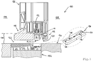
- FIG. 1 shows an additional lock for a door frame and a door having door assembly, wherein the additional lock is designated by the reference numeral 10. Moreover, in FIG. 1 shown a door assembly, which is designated by the reference numeral 100.
- the door assembly 100 has a door frame 102, of which only a lower portion is shown.
- the door assembly 100 has a door frame 102 pivotally mounted on the door leaf 106, of which also only a lower portion is shown.
- the door leaf 106 serves to separate an inner side 108 (secured side) from an outer side 110 (unsecured side).
- the door leaf 106 has on the underside a drive rod 112 with a locking pin.
- the additional lock 10 is mounted on the underside of the door leaf 106, for example screwed, and cooperates with a locking pin of the drive rod 112.
- the additional lock 10 serves to bridge the folding air 114 between the underside of the door leaf 106 and a lower part of the door frame 102.
- the door panel 106 is a conventional door panel with rollover 116 (door panel has rollover 116).
- the door leaf 106 has a cover strip 118, which is arranged in the region of the folded air 114.
- the additional lock 10 is arranged between the cover strip 118 and rollover 116.
- Panel 118, additional latch 10 and rollover 116 form towards the lower part of the door frame 102 toward a nearly flush surface 120 (deviation ⁇ 2 mm). In the illustrated state, the door leaf 106 is not locked to the door frame 102.
- a floor sill 122 is arranged, which forms a flush surface with a floor 124 adjacent to the floor sill 122.
- a strike plate 126 is integrated, which is also arranged flush with the floor 124.
- the striking plate 126 has two locking openings 128.
- the locking apertures 128 taper toward the center of the striker 126 so that a latch member, such as a pivot latch, can engage the latch apertures 128 at the tapers.
- the strike plate 126 has fastening passages 130, on which the strike plate 126 can be screwed, for example.
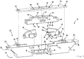
- the additional lock 10 has a housing 12, a displaceable coupling element 14 and two pivot bars 16, 18 (see FIG. 2 and 3 ).
- the coupling element 14 has on a first side 20 of the housing 12 a receptacle 22 which is adapted to receive a locking pin of a drive rod 112 of the door assembly 100.
- the pivot bolt 16, 18 are by displacing the coupling member 14 between a pivoted Position (open position or unlocked position) and a pivoted position (locking position) pivotable.
- the pivot bolt 16, 18 is in the pivoted position on a side facing away from the first side 20 side 24 for the purpose of locking out of the housing 12 (see Figure 4c with protruding pivot bolt 16).
- pivot bolt 16, 18 have an identical structure and are provided for reasons of clarity partially only once with reference numerals.
- the coupling element 14 is mounted on a support 26 displaceably in the housing 12, so that the coupling element 14 is translationally displaceable (see FIG. 3 ). For this purpose, sliding portions 28 of the coupling element 14 rest on the support 26.
- the support 26 is designed as a surface of an inner frame 30 of the housing 12 which faces the first side 20 of the housing.
- the pivot bolt 16 serves to lock the door leaf 106 on the door frame 102 (see FIG. 1 ). In this case, the pivot bolt 16 engage in the swung-out state in a locking opening 128 of the strike plate 126.
- There is another pivot bolt 18 is provided which serves to achieve a tilted position of the door leaf 102. For this purpose, the further pivot bolt 18 can also engage in a locking opening 128 of the striking plate 126.
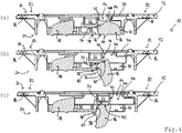
- the coupling element 14 is located in a central position between a first end position and a second end position, the pivot bolt 16, 18 are pivoted (see FIG. 2 . 3 and 4a ). This corresponds to an unlocked position or rotational position in which the door leaf 106 can be pivoted.
- the (first) pivot bolt 16 is pivoted to the pivoted position (see Figure 4c ). This corresponds to a locked position in which the door leaf 106 can not be pivoted.
- the further pivot bolt 18 is in the pivoted position.
- the further pivot bolt 16 is pivoted to the pivoted position (not shown). This corresponds to a tilted position in which the door leaf 106 can be tilted.
- the (first) pivot bolt 16 is in the pivoted position.
- the pivot bolt 16, 18 have pin portions 32, by means of which the pivot bolt 16, 18 are each pivotally mounted in a recess 12 formed on the housing 12 (see FIG. 3 ). As a result, the pivot bolt 16, 18 each pivotable about a pivot axis 36, 38.
- the trough 34 is formed on the inner frame 30.
- the pivot bolt 16, 18 each have a guide portion 40 which cooperates with the displacement of the coupling element 14 in an end position at which the respective pivot bolt 16, 18, with a guide cam 42 of the coupling element 14, that the pivot bolt 16, 18 in the pivoted position is pivoted (see FIG. 3 and 4 with pivoted pivot bolt 16).
- the translational movement of the coupling element 14 is thereby in a Swivel movement of the pivot bolt 16 converted.
- the guide portion 40 is located in the pivoted position of the pivot bolt 16, 18 within a guide slot 44 of the coupling element fourteenth
- the pivoting bars 16, 18 have a nose portion 46 which, when displacing the coupling element 14 from an end position in the direction of the central position of such a pocket 48 of the coupling element 14 (see FIG. 6 ) cooperates, that the pivot bolt 16, 18 is pivoted in the pivoted position.
- the nose portion 46 cooperates with a return portion 50 of the pocket 48 of the coupling element 14. If the coupling element 14 is displaced from an end position in the direction of the central position, the nose portion 46 slides along the return portion 50, so that the pivot bolt 16, 18 is pivoted to the pivoted position (see Fig.2 and 3 ).
- the pivot bars 16, 18 are secured in the pivoted position respectively by contact of the nose portion 46 with an end face 52 of the pocket 48.
- the end face 52 is located at the opposite end of the return portion 50 of the bag 48.
- the pivot bolt 16, 18 in the swung-out position respectively by contact of the guide portion 40 with an end portion 54 of the guide curve 42 secured (see Fig. 4c ).
- the pivot bolt 16, 18 each have a stop surface 56, with which the pivot bolt 16, 18 in the pivoted position with a stop portion 58 of the housing 12 in contact (see 4c ).
- the pivot bolt 16, 18 each have a step 60, with which the pivot bolt 16, 18 in the pivoted position engages behind the abutment portion 58 of the housing 12.
- the pivot bolt 16, 18 have at the nose portion 46 on a leading edge 62, with the pivot bolt 16, 18 in the pivoted position with an adjoining the pocket 48 contact portion 64 in contact (see Figure 3 ).
- the contact portion 64 forms a portion of the sliding portions 28.
- the pivot bars 16, 18 have an enlarged end portion 66 which is adapted to engage behind a locking opening 128 of the striking plate 126 (see Figure 3 ).
- the pivot bolt 16, 18 a reinforced latch portion 68, via which the pivot bolt 16, 18 can laterally contact the support 26 (inner frame 30) in the housing 12 in contact.
- the coupling element 14 has lateral webs 70, with which the coupling element 14 is guided in formed on the housing 12 recesses 72.
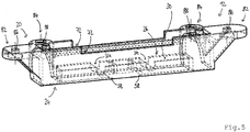
- the recesses 72 are closed at the first side 20 of the housing 12 by a cover 74 (see Fig.2 and 3 ).
- the housing 12 is flush with the first side 20 by means of a cover 74, wherein the cover 74 has a passage 76 for a locking pin.
- the passage 76 has an elongate cross section.
- an enlarged passage section 78 is centrally formed, through which a locking pin can be performed through the passage 76.
- the passage 76 may be formed such that the locking pin, the adjoining the enlarged passage section 78 sections 80th engages behind. Performing the locking pin would thus be possible only in the extended passage section 78.
- the cover 74 also has fastening passages 79 by means of which the cover 74 can be fastened to the housing 12, for example screwed or riveted.
- a strike plate 126 is provided, in which at least one of the pivot bolt 16, 18 engages in the swung-out position (see closing plate Fig. 1 ).
- the housing 12 has attachment tabs 82 and / or lateral attachment tabs 84 with passages 86, 88, with which the additional lock 10 attached to a door assembly 100, in particular can be screwed.
Abstract
Eine Zusatzverriegelung (10) für eine einen Türrahmen und einen Türflügel aufweisende Türanordnung, wobei die Zusatzverriegelung (10) ein Gehäuse (12), ein verlagerbares Kupplungselement (14) und mindestens einen Schwenkriegel (16, 18) aufweist, ist im Hinblick auf eine Falzluft überbrückende Verriegelung mit einfachen konstruktiven Mitteln derart ausgestaltet und weitergebildet, dass das Kupplungselement (14) an einer ersten Seite (20) des Gehäuses (12) eine Aufnahme (22) aufweist, die dazu eingerichtet ist, einen Schließzapfen einer Treibstange (112) der Türanordnung (100) aufzunehmen, dass der Schwenkriegel (16, 18) durch Verlagern des Kupplungselements (14) zwischen einer eingeschwenkten Stellung und einer ausgeschwenkten Stellung verschwenkbar ist und dass der Schwenkriegel (16, 18) in der ausgeschwenkten Stellung an einer von der ersten Seite (20) abgewandten Seite (24) aus dem Gehäuse (12) hervorsteht.An additional lock (10) for a door assembly comprising a door frame and a door leaf, wherein the auxiliary lock (10) comprises a housing (12), a displaceable coupling element (14) and at least one pivot bolt (16, 18) is in view of a rabbet air bridging lock with simple structural means designed and further developed such that the coupling element (14) on a first side (20) of the housing (12) has a receptacle (22) which is adapted to a locking pin of a drive rod (112) of the door assembly (100) that the pivot bolt (16, 18) is pivotable by displacing the coupling element (14) between a pivoted position and a pivoted position and that the pivot bolt (16, 18) in the pivoted position at one of the first side (16 20) facing away from the housing (12) protrudes side (24).
Eine Türanordnung mit einem Türrahmen, einem schwenkbar am Türrahmen gelagerten Türflügel und einer solchen Zusatzverriegelung ist angegeben.

Description
Die Erfindung betrifft eine Zusatzverriegelung für eine einen Türrahmen und einen Türflügel aufweisende Türanordnung, wobei die Zusatzverriegelung ein Gehäuse, ein verlagerbares Kupplungselement und mindestens einen Schwenkriegel aufweist. Zudem betrifft die Erfindung eine Türanordnung mit einem Türrahmen, einem schwenkbar am Türrahmen gelagerten Türflügel und mit einer solchen Zusatzverriegelung.The invention relates to an additional lock for a door frame and a door having door assembly, wherein the additional locking comprises a housing, a displaceable coupling element and at least one pivot bolt. In addition, the invention relates to a door assembly with a door frame, a pivotally mounted on the door frame door leaf and with such additional locking.
Aus dem Stand der Technik sind Türanordnungen und Verriegelungen für Türanordnungen bekannt. Beispielsweise ist in
Allerdings ist bei diesem Türschwellensystem problematisch, dass dieses auf Grund des Adapterprofils nebst Endkappen einen komplexen Aufbau aufweist. Herstellung und Montage des Türschwellensystems sind aufwändig. Eine Verriegelung ist speziell an das Türschwellensystem anzupassen und in das Adapterprofil zu integrieren.However, in this door sill system is problematic that this has a complex structure due to the adapter profile together with end caps. Production and installation of the door sill system are complex. An interlock must be specially adapted to the door sill system and integrated in the adapter profile.
Der Erfindung liegt die Aufgabe zugrunde, bei einer Türanordnung mit einfachen konstruktiven Mitteln eine Falzluft überbrückende Verriegelung zu ermöglichen. Eine Nachrüstlösung ist wünschenswert.The invention has for its object to allow for a door assembly with simple structural means a folding air bridging lock. A retrofit solution is desirable.
Die Erfindung löst die Aufgabe durch eine Zusatzverriegelung mit den Merkmalen des Anspruchs 1. Danach zeichnet sich die Zusatzverriegelung dadurch aus, dass das Kupplungselement an einer ersten Seite des Gehäuses eine Aufnahme aufweist, die dazu eingerichtet ist, einen Schließzapfen einer Treibstange der Türanordnung aufzunehmen, dass der Schwenkriegel durch Verlagern des Kupplungselements zwischen einer eingeschwenkten Stellung (Offenstellung) und einer ausgeschwenkten Stellung (Verriegelungsstellung) verschwenkbar ist und dass der Schwenkriegel in der ausgeschwenkten Stellung an einer von der ersten Seite abgewandten Seite zum Zwecke der Verriegelung aus dem Gehäuse hervorsteht. Damit ist ein Türflügel am Türrahmen festlegbar.The invention achieves the object by an additional locking with the features of claim 1. Thereafter, the additional locking is characterized in that the coupling element has on a first side of the housing a receptacle which is adapted to receive a locking pin of a drive rod of the door assembly that the pivot bolt by displacement of the coupling element between a pivoted position (open position) and a pivoted position (locking position) is pivotable and that the pivot bolt protrudes in the pivoted position on a side facing away from the first side for the purpose of locking out of the housing. This allows a door leaf to be fixed to the door frame.
Mit der Zusatzverriegelung ist eine Adaption der Verriegelung eines herkömmlichen Türflügels (bspw. Türflügel mit Überschlag) an eine barrierefreie Türanordnung möglich (Schwellenhöhe bezogen auf das Niveau eines Fußbodens kleiner 20 Millimeter). Die Zusatzverriegelung dient zur Überbrückung der Falzluft zwischen Türflügelunterseite und dem unteren Teil eines Türrahmens bzw. einer dort angeordneten Türschwelle. Die anschraubbare Zusatzverriegelung kann an der Türanordnung, beispielsweise an einem Türflügel, montiert werden und wandelt die lineare (translatorische) Bewegung eines Schließzapfens einer Treibstange in eine Schwenkbewegung des Schwenkriegels um, der zur Verriegelung in die gegenüberliegende Komponente einer Türanordnung, beispielsweise einer Türschwelle, eingreift. Eine Anpassung eines Adapterprofils nebst zugehörigen Endkappen sowie einer Verriegelung ist nicht erforderlich. Die an der Türanordnung vorhandene Beschlagtechnik, beispielsweise eine türflügelseitig montierte Treibstange mit Schließzapfen, kann beibehalten werden. Lediglich die als Nachrüstset ausgebildete Zusatzverriegelung ist hierfür bei Bedarf entsprechend nachzurüsten.With the additional locking, it is possible to adapt the locking of a conventional door leaf (eg door leaf with rollover) to a barrier-free door arrangement (threshold height relative to the level of a floor of less than 20 millimeters). The additional locking serves to bridge the seaming air between the door leaf underside and the lower part of a door frame or a door sill arranged there. The Screw-on auxiliary locking can be mounted on the door assembly, such as a door leaf, and converts the linear (translational) movement of a locking pin of a drive rod in a pivotal movement of the pivot bolt, which engages for locking in the opposite component of a door assembly, such as a door threshold. An adaptation of an adapter profile along with associated end caps and a lock is not required. The existing on the door assembly fitting technology, such as a door leaf-mounted drive rod with locking pin can be maintained. Only the additional locking designed as a retrofit set is to be retrofitted accordingly if necessary.
Die Zusatzverriegelung, die auch als Adapterverschluss bezeichnet werden kann, lässt sich an verschiedenen Profilsystemen (Türanordnung mit Holz-, Aluminium oder Kunststoffprofil) verwenden. Das Gehäuse der Zusatzverriegelung kann beispielsweise eine Höhe von 10 bis 30 Millimeter, vorzugsweise 15 bis 25 Millimeter, weiter vorzugsweise 20 Millimeter aufweisen. Abweichungen von ± 2 Millimeter gelten als von den angegebenen Bereichen mit umfasst.The additional locking, which can also be referred to as adapter closure, can be used on various profile systems (door arrangement with wood, aluminum or plastic profile). The housing of the additional locking may for example have a height of 10 to 30 millimeters, preferably 15 to 25 millimeters, more preferably 20 millimeters. Deviations of ± 2 mm are considered to be included in the ranges indicated.
Die Zusatzverriegelung dient als Adapter zur Verwendung der Verriegelung eines herkömmlichen Türflügels (bspw.
Türflügel mit Überschlag) an einem Türrahmen ohne Türanschlag, insbesondere mit ebener Schwelle (sogen. "Null-Schwelle" mit 0 Millimeter Schwellenhöhe, die mit umgebender Bodenfläche bündig ist). Bei dem Türflügel kann es sich um einen Schwenkflügel oder einen Schwenk-Kipp-Flügel handeln.
Der Schwenkriegel kann zur Verriegelung eines Türflügels am Türrahmen dienen. Hierbei kann der Schwenkriegel mit einer Schließausnehmung in Eingriff gelangen, wobei an oder in der Schließausnehmung ein Schließblech angeordnet sein kann.The additional locking serves as an adapter for using the lock of a conventional door leaf (eg.
Door leaf with rollover) on a door frame without a door stop, in particular with a flat threshold (so-called "zero threshold" with 0 mm threshold height, which is flush with the surrounding floor surface). The door can be a swing-wing or a pan-tilt-wing.
The pivot bolt can serve to lock a door leaf on the door frame. Here, the pivot bolt with a locking recess engage, wherein on or in the closing recess a strike plate can be arranged.
Es kann ein weiterer Schwenkriegel vorgesehen sein, der dazu dient, eine Kippstellung des Türflügels zu bewirken. Der Türflügel ist dann als Schwenk-Kipp-Flügel ausgebildet. Hiermit kann mit einem herkömmlichen Türflügel an einem Türrahmen mit ebener Schwelle auch eine Kipp-Funktion bereitgestellt werden.It may be provided a further pivot bolt which serves to cause a tilting position of the door leaf. The door is then designed as a pan-tilt wing. This can be provided with a conventional door leaf on a door frame with a flat threshold and a tilting function.
Im Konkreten kann das Kupplungselement auf einer Auflage verschieblich im Gehäuse gelagert sein. Dadurch ist eine definierte translatorische Bewegung des Kupplungselements ermöglicht. Das Kupplungselement kann auch als "Schlitten" bezeichnet werden. Die Auflage kann als im Gehäuse angeordneter Innenrahmen ausgebildet sein, auf dessen der ersten Seite des Gehäuses zugewandten Seite das Kupplungselement verschieblich gelagert ist.Specifically, the coupling element can be mounted on a support displaceable in the housing. This allows a defined translational movement of the coupling element. The coupling element can also be referred to as a "slide". The support may be formed as arranged in the housing inner frame, on whose side facing the first side of the housing, the coupling element is slidably mounted.
In vorteilhafter Weise kann das Kupplungselement mit dem mindestens einen Schwenkriegel zusammenwirken. Das Kupplungselement ist von einer Mittellage in eine erste Endlage und/oder eine zweite Endlage verlagerbar. Befindet sich das Kupplungselement in der Mittellage zwischen der ersten und zweiten Endlage sind vorzugsweise beide Schwenkriegel eingeschwenkt (Offen- oder Drehstellung). Der Türflügel kann dann verschwenkt werden. Bei einer Verlagerung des Kupplungselements in eine erste Endlage kann der erste Schwenkriegel in die ausgeschwenkte Stellung verschwenkt werden (Verriegelungsstellung). Der Türflügel kann dann nicht verschwenkt werden. Ein ggf. vorhandener weiterer Schwenkriegel ist vorzugsweise eingeschwenkt. Ist der weitere Schwenkriegel vorhanden, kann bei einer Verlagerung des Kupplungselements in eine zweite Endlage der weitere Schwenkriegel in die ausgeschwenkte Stellung verschwenkt werden. Der Türflügel kann dann gekippt werden. Der erste Schwenkriegel ist dann vorzugsweise eingeschwenkt.Advantageously, the coupling element can cooperate with the at least one pivot bolt. The coupling element is displaceable from a central position into a first end position and / or a second end position. If the coupling element is located in the middle position between the first and second end position, preferably both pivot bolts are pivoted in (open or rotary position). The door can then be pivoted. In a displacement of the coupling element in a first end position of the first pivot bolt can be pivoted in the pivoted position (locking position). The door can then not be pivoted. A possibly existing further pivot bolt is preferably pivoted. If the further pivot bolt is present, can in a displacement of the coupling element in a second end position the further pivot bolt are pivoted in the pivoted position. The door can then be tilted. The first pivot bolt is then preferably pivoted.
Im Rahmen einer bevorzugten Ausgestaltung kann zumindest einer der Schwenkriegel Zapfenabschnitte aufweisen, mittels denen der Schwenkriegel in einer am Gehäuse ausgebildeten Mulde schwenkbar gelagert ist. Hiermit ist eine konstruktiv einfache und stabile Schwenkmöglichkeit geschaffen. Eine einfache Montage ist ermöglicht, da die Schwenkriegel mit den Zapfenabschnitten einfach in die Mulden eingesetzt werden können, bspw. durch Einsetzen der Schwenkriegel von der ersten Seite des Gehäuses aus.As part of a preferred embodiment, at least one of the pivot bolt have pin portions, by means of which the pivot bolt is pivotally mounted in a recess formed on the housing. Hereby a structurally simple and stable pivoting possibility is created. A simple assembly is possible, since the pivot bolt with the pin portions can be easily inserted into the wells, for example. By inserting the pivot bolt from the first side of the housing.
Vorteilhafterweise kann zumindest einer der Schwenkriegel einen Führungsabschnitt aufweisen, der beim Verlagern des Kupplungselements in eine Endlage derart mit einer Führungskurve des Kupplungselements zusammenwirkt, dass der Schwenkriegel in die ausgeschwenkte Stellung verschwenkt wird. Eine einfache Umwandlung einer translatorischen Bewegung in eine Schwenkbewegung mit möglichst wenigen Bauteilen ist ermöglicht. Mit "Endlage" ist die Endlage gemeint, an der sich der Schwenkriegel befindet. Anders ausgedrückt wird der jeweilige Schwenkriegel in die ausgeschwenkte Stellung verschwenkt, wenn das Kupplungselement in Richtung dieses Schwenkriegels in seine Endlage verlagert wird. Im eingeschwenkten Zustand des Schwenkriegels kann der Führungsabschnitt in einem im Kupplungselement ausgebildeten Führungsschlitz angeordnet sein.
Zweckmäßigerweise kann zumindest einer der Schwenkriegel einen Nasenabschnitt aufweisen, der beim Verlagern des Kupplungselements aus einer Endlage in Richtung der Mittellage derart mit einer Tasche des Kupplungselements zusammenwirkt, dass der Schwenkriegel in die eingeschwenkte Stellung verschwenkt wird. Hiermit ist eine einfache und zuverlässige Bauweise geschaffen. Eine federlose Ausführung ist ermöglicht. Da auf eine Feder verzichtet werden kann, tritt ein Ermüdungsbruch einer Feder gar nicht erst auf.Advantageously, at least one of the pivot bolt may have a guide portion which cooperates with the displacement of the coupling element in an end position with a guide cam of the coupling element, that the pivot bolt is pivoted into the pivoted position. A simple conversion of a translational movement in a pivoting movement with as few components is possible. By "end position" is meant the end position at which the pivot bolt is located. In other words, the respective pivot bolt is pivoted to the pivoted position when the coupling element is displaced in the direction of this pivot bolt in its end position. In the pivoted state of the pivot bolt, the guide section can be arranged in a guide slot formed in the coupling element.
Conveniently, at least one of the pivot bolt may have a nose portion which in the displacement of the coupling element from an end position in the direction of the central position so with a pocket of the coupling element cooperates, that the pivot bolt is pivoted in the pivoted position. This creates a simple and reliable design. A springless design is possible. Since it is possible to dispense with a spring, a fatigue fracture of a spring does not occur at all.
Im Rahmen einer bevorzugten Ausgestaltung kann zumindest einer der Schwenkriegel in der ausgeschwenkten Stellung durch Kontakt des Nasenabschnitts mit einer Endfläche der Tasche des Kupplungselements und/oder durch Kontakt des Führungsabschnitts mit einem Endabschnitt der Führungskurve des Kupplungselements gesichert sein. Eine Sicherung des Schwenkriegels in der ausgeschwenkten Stellung ist geschaffen. Dadurch ermöglichen Manipulationen am Schwenkriegel keine Betätigung des Kupplungselements. Eine Öffnung durch Manipulationen am Schwenkriegel ist damit nicht möglich.In a preferred embodiment, at least one of the pivot bolt in the pivoted position by contact of the nose portion with an end face of the pocket of the coupling element and / or be secured by contact of the guide portion with an end portion of the guide cam of the coupling element. A backup of the pivot bolt in the pivoted position is created. This allows manipulation of the pivot bolt no actuation of the coupling element. An opening by manipulation of the pivot bolt is thus not possible.
Im Konkreten kann zumindest einer der Schwenkriegel eine Anschlagfläche aufweisen, mit der der Schwenkriegel in der ausgeschwenkten Stellung mit einem Anschlagabschnitt des Gehäuses in Kontakt ist. Somit wird eine definierte ausgeschwenkte Stellung erreicht. Durch Anlage am Anschlagabschnitt wird die ausgeschwenkte Stellung weiter stabilisiert.
Vorteilhafterweise kann zumindest einer der Schwenkriegel an der Anschlagfläche eine Stufe aufweisen, mit der der Schwenkriegel in der ausgeschwenkten Stellung den Anschlagabschnitt des Gehäuses hintergreift. Hierdurch ist die Stabilität in der ausgeschwenkten Stellung weiter erhöht. Ein Hineindrücken des Schwenkriegels in das Gehäuse kann durch die Stufe verhindert werden.Specifically, at least one of the pivot bolt may have a stop surface with which the pivot bolt is in the pivoted position with a stop portion of the housing in contact. Thus, a defined swung-out position is achieved. By attaching to the stop section, the pivoted position is further stabilized.
Advantageously, at least one of the pivot bolt on the stop surface have a step with which the pivot bolt in the pivoted position engages behind the stop portion of the housing. As a result, the stability in the pivoted position is further increased. Pushing the pivot bolt into the housing can be prevented by the step.
Zweckmäßigerweise kann zumindest einer der Schwenkriegel am Nasenabschnitt eine Führungskante aufweisen, mit der der Schwenkriegel in der eingeschwenkten Stellung mit einem sich an die Tasche des Kupplungselement anschließenden Kontaktabschnitt des Kupplungselements in Kontakt ist. Damit ist der Schwenkriegel in der eingeschwenkten Stellung gesichert. Unerwünschtes Ausschwenken des Schwenkriegels ist damit verhindert.Conveniently, at least one of the pivot bolt on the nose portion having a leading edge, with which the Swivel bolt in the pivoted position with a subsequent to the pocket of the coupling element contact portion of the coupling element in contact. Thus, the pivot bolt is secured in the pivoted position. Unwanted pivoting of the pivot bolt is thus prevented.
Im Konkreten kann zumindest einer der Schwenkriegel einen erweiterten Endabschnitt und/oder einen verstärkten Riegelabschnitt aufweisen. Durch den am freien Ende angeordneten Endabschnitt ist ein Hintergriff mit einer Schließöffnung und/oder einem Schließblech geschaffen. Der verstärkte Abschnitt erhöht Stabilität des Schwenkriegels. Über den verstärkten Abschnitt kann der Schwenkriegel seitlich mit der Auflage (Innenrahmen) im Gehäuse in Kontakt gelangen.Specifically, at least one of the pivot bolt may have an enlarged end portion and / or a reinforced latch portion. By arranged at the free end end portion, a rear handle is provided with a closing opening and / or a strike plate. The reinforced section increases stability of the pivot bolt. About the reinforced section of the pivot bolt can laterally come into contact with the support (inner frame) in the housing.
Vorteilhafterweise kann das Kupplungselement seitliche Stege aufweisen, mit denen das Kupplungselement in am Gehäuse ausgebildeten Aussparungen geführt ist. Die Führung des Kupplungselements wird damit weiter verbessert. Die Stege und die Aussparungen können entlang der Verschieberichtung des Kupplungselements als Begrenzung dienen. Die Orientierung des Kupplungselements im Gehäuse kann damit sichergestellt werden.Advantageously, the coupling element may have lateral webs, with which the coupling element is guided in recesses formed on the housing. The leadership of the coupling element is thus further improved. The webs and the recesses may serve as a limit along the direction of displacement of the coupling element. The orientation of the coupling element in the housing can thus be ensured.
Im Rahmen einer bevorzugten Ausgestaltung kann das Gehäuse an der ersten Seite mittels einer Abdeckung bündig verschlossen sein, wobei die Abdeckung einen Durchgang für einen Schließzapfen aufweist. Durch die Abdeckung ist die Anordnung von Komponenten in dem Gehäuse sichergestellt. Die Komponenten der Zusatzverriegelung sind vor Umwelteinflüssen geschützt. Der Durchgang kann einen länglichen Querschnitt und einen bspw. mittig angeordneten erweiterten Durchgangsabschnitt aufweisen, durch den ein Schließzapfen einer Treibstange eingeführt werden kann. In der Abdeckung können zudem Befestigungsdurchgänge ausgebildet sein, über die die Abdeckung an dem Gehäuse verschraubt oder vernietet sein kann.As part of a preferred embodiment, the housing may be flush on the first side by means of a cover, wherein the cover has a passage for a locking pin. The cover ensures the arrangement of components in the housing. The components of the additional locking system are protected against environmental influences. The passage may have an elongate cross-section and a, for example, centrally disposed extended passage section, through which a Locking pin a drive rod can be inserted. In addition, fastening passages may be formed in the cover, via which the cover may be screwed or riveted to the housing.
Zweckmäßigerweise kann ein Schließblech vorgesehen sein, in das zumindest einer der Schwenkriegel in der ausgeschwenkten Stellung eingreift. Hiermit lässt sich eine sichere und stabile Verriegelung erzielen. Durch das Schließblech kann eine Verletzung einer Schließausnehmung verhindert werden. Ein Hintergriff zwischen Schließblech und Schwenkriegel ist möglich. Zur Aufnahme von zwei Schwenkriegeln kann das Schließblech zwei Verriegelungsöffnungen aufweisen. Zudem kann das Schließblech Befestigungsdurchgänge aufweisen, so dass das Schließblech beispielsweise mittels Schrauben befestigt werden kann.Appropriately, a strike plate may be provided, engages in the at least one of the pivot bolt in the pivoted position. This can be a secure and stable locking achieve. Through the strike plate a violation of a closing recess can be prevented. A rear grip between the strike plate and pivot bolt is possible. For receiving two pivot bolts, the strike plate may have two locking openings. In addition, the strike plate can have fastening passages, so that the strike plate can be fastened by means of screws, for example.
Die eingangs genannte Aufgabe wird auch durch eine Türanordnung mit den Merkmalen des nebengeordneten Anspruchs gelöst. Die Türanordnung ist ausgestattet mit einem Türrahmen, einem schwenkbar am Türrahmen gelagerten Türflügel und mit einer Zusatzverriegelung wie voranstehend beschrieben. Hiermit lassen sich die gleichen Vorteile erzielen wie mit der Zusatzverriegelung, so dass auf die dortigen Ausführungen verwiesen wird.The object mentioned is also achieved by a door assembly with the features of the independent claim. The door assembly is equipped with a door frame, a pivotally mounted on the door frame door leaf and with an additional lock as described above. Hereby, the same advantages can be achieved as with the additional locking, so that reference is made to the statements there.
Die Zusatzverriegelung kann insbesondere in der Falzluft zwischen der Türflügelunterkante und dem unteren Teil eines Türrahmens bzw. einer dort angeordneten Türschwelle angeordnet sein, beispielsweise kann die Zusatzverriegelung an der Türflügelunterkante montiert sein. Der Türrahmen kann mit einer ebenen Bodenschwelle ("Null-Schwelle") wie oben beschrieben ausgebildet sein.The additional locking can be arranged in particular in the seaming air between the lower edge of the door leaf and the lower part of a door frame or a door threshold arranged there, for example, the additional locking can be mounted on the lower edge of the door leaf. The door frame may be formed with a flat threshold ("zero threshold") as described above.
Bei dem Türflügel kann es sich um einen herkömmlichen Türflügel mit Überschlag handeln. Der Türflügel kann eine Treibstange mit Schließzapfen aufweisen, wobei die Treibstange mittels einer Handhabe betätigt werden kann. Die Zusatzverriegelung kann derart montiert werden, dass das Kupplungselement einen Schließzapfen der Treibstange insbesondere formschlüssig aufnimmt. Die translatorische Bewegung des Schließzapfens kann dann durch Zusammenwirken von Kupplungselement und Schwenkriegel in eine Schwenkbewegung umgewandelt werden. Der Türflügel kann zudem eine Blendleiste aufweisen, die im Bereich der Falzluft an der Türflügelunterseite angeordnet ist. Die Zusatzverriegelung kann zwischen Blendleiste und Überschlag angeordnet sein.The door can be a conventional door with rollover. The door can have a drive rod with locking pin, wherein the drive rod can be actuated by means of a handle. The additional locking can be mounted such that the coupling element receives a locking pin of the drive rod in particular form-fitting manner. The translational movement of the locking pin can then be converted into a pivoting movement by the interaction of coupling element and pivot bolt. The door leaf can also have a cover strip, which is arranged in the region of the folding air on the door leaf base. The additional lock can be arranged between the cover strip and rollover.
Zudem kann an der der Zusatzverriegelung gegenüberliegenden Komponente, beispielsweise am Türrahmen oder der Türschwelle, eine Schließausnehmung und/oder ein Schließblech angeordnet sein.
Die Erfindung wird im Folgenden anhand der Figuren näher erläutert. Gleiche oder funktional gleiche Komponenten sind teilweise nur einmal mit Bezugszeichen versehen. Es zeigen:
- Fig.1
- ein Ausführungsbeispiel einer Zusatzverriegelung und einer Türanordnung in einer Schnittansicht;
- Fig.2
- die Zusatzverriegelung aus
Fig.1 in einer perspektivischen Ansicht; - Fig.3
- die Zusatzverriegelung aus
Fig.1 in Explosionsdarstellung in einer perspektivischen und teilweise geschnittenen Ansicht; - Fig.4a-4c
- die Zusatzverriegelung aus
Fig.1 in mehreren Längsschnitten mit einem Schwenkriegel in unterschiedlichen Stellungen; - Fig.5
- das Gehäuse der Zusatzverriegelung aus
Fig.1 in einer transparenten Ansicht; und - Fig.6
- das Kupplungselement der Zusatzverriegelung aus
Fig.1 in einer transparenten Ansicht.
The invention will be explained in more detail below with reference to FIGS. The same or functionally identical components are sometimes only once provided with reference numerals. Show it:
- Fig.1
- an embodiment of an additional lock and a door assembly in a sectional view;
- Fig.2
- the additional locking off
Fig.1 in a perspective view; - Figure 3
- the additional locking off
Fig.1 in an exploded view in a perspective and partially sectioned view; - 4a-4c
- the additional locking off
Fig.1 in several longitudinal sections with a pivot bolt in different positions; - Figure 5
- the housing of the additional locking
Fig.1 in a transparent view; and - Figure 6
- the coupling element of the additional locking
Fig.1 in a transparent view.
Die Türanordnung 100 weist einen Türrahmen 102 auf, von dem lediglich ein unterer Abschnitt dargestellt ist. Zudem weist die Türanordnung 100 einen am Türrahmen 102 schwenkbar gelagerten Türflügel 106 auf, von dem ebenfalls lediglich ein unterer Abschnitt dargestellt ist. Der Türflügel 106 dient zur Abtrennung einer Innenseite 108 (gesicherte Seite) von einer Außenseite 110 (ungesicherte Seite).The
Der Türflügel 106 weist an der Unterseite eine Treibstange 112 mit einem Schließzapfen auf. Die Zusatzverriegelung 10 ist an der Unterseite des Türflügels 106 montiert, beispielsweise verschraubt, und wirkt mit einem Schließzapfen der Treibstange 112 zusammen. Dabei dient die Zusatzverriegelung 10 zur Überbrückung der Falzluft 114 zwischen der Unterseite des Türflügels 106 und einem unteren Teil des Türrahmens 102.The
Bei dem Türflügel 106 handelt es sich um einen herkömmlichen Türflügel mit Überschlag 116 (Türflügelprofil weist Überschlag 116 auf). Zudem weist der Türflügel 106 eine Blendleiste 118 auf, die im Bereich der Falzluft 114 angeordnet ist. Die Zusatzverriegelung 10 ist zwischen Blendleiste 118 und Überschlag 116 angeordnet. Blendleiste 118, Zusatzverriegelung 10 und Überschlag 116 bilden zum unteren Teil des Türrahmens 102 hin eine nahezu bündige Oberfläche 120 aus (Abweichung ± 2 Millimeter). Im dargestellten Zustand ist der Türflügel 106 nicht am Türrahmen 102 verriegelt.The
Am Türrahmen 102 ist eine Bodenschwelle 122 angeordnet, die mit einem an die Bodenschwelle 122 angrenzenden Fußboden 124 eine bündige Oberfläche ausbildet. In die Bodenschwelle 122 ist ein Schließblech 126 integriert, welches ebenfalls bündig zum Fußboden 124 angeordnet ist. Das Schließblech 126 weist zwei Verriegelungsöffnungen 128 auf. Die Verriegelungsöffnungen 128 verjüngen sich zur Mitte des Schließblechs 126 hin, so dass ein Riegelelement, beispielsweise ein Schwenkriegel, die Verriegelungsöffnungen 128 an den Verjüngungen hintergreifen kann. Das Schließblech 126 weist Befestigungsdurchgänge 130 auf, an denen das Schließblech 126 bspw. verschraubt werden kann.
Die Zusatzverriegelung 10 weist ein Gehäuse 12, ein verlagerbares Kupplungselement 14 und zwei Schwenkriegel 16, 18 auf (siehe
The
Die Schwenkriegel 16, 18 sind durch Verlagern des Kupplungselements 14 zwischen einer eingeschwenkten Stellung (Offenstellung oder unverriegelte Stellung) und einer ausgeschwenkten Stellung (Verriegelungsstellung) verschwenkbar. Der Schwenkriegel 16, 18 steht in der ausgeschwenkten Stellung an einer von der erste Seite 20 abgewandten Seite 24 zum Zwecke der Verriegelung aus dem Gehäuse 12 hervor (siehe
Im vorliegenden Ausführungsbeispiel weisen die Schwenkriegel 16, 18 einen identischen Aufbau auf und sind aus Gründen der Übersichtlichkeit teilweise nur einmal mit Bezugszeichen versehen.In the present embodiment, the
Das Kupplungselement 14 ist auf einer Auflage 26 verschieblich im Gehäuse 12 gelagert, so dass das Kupplungselement 14 translatorisch verlagerbar ist (siehe
Der Schwenkriegel 16 dient zur Verriegelung des Türflügels 106 am Türrahmen 102 (siehe
The
Befindet sich das Kupplungselement 14 in einer Mittellage zwischen einer ersten Endlage und einer zweiten Endlage, sind die Schwenkriegel 16, 18 eingeschwenkt (siehe
Ist das Kupplungselement 14 in eine erste Endlage verlagert (in
Ist das Kupplungselement 14 in eine zweite Endlage verlagert (in
Die Schwenkriegel 16, 18 weisen Zapfenabschnitte 32 auf, mittels denen die Schwenkriegel 16, 18 jeweils in einer am Gehäuse 12 ausgebildeten Mulde 34 schwenkbar gelagert sind (siehe
Die Schwenkriegel 16, 18 weisen jeweils einen Führungsabschnitt 40 auf, der beim Verlagern des Kupplungselements 14 in eine Endlage, an der sich der betreffende Schwenkriegel 16, 18 befindet, derart mit einer Führungskurve 42 des Kupplungselements 14 zusammenwirkt, dass der Schwenkriegel 16, 18 in die ausgeschwenkte Stellung verschwenkt wird (siehe
Die Schwenkriegel 16, 18 weisen einen Nasenabschnitt 46 auf, der beim Verlagern des Kupplungselements 14 aus einer Endlage in Richtung der Mittellage derart einer Tasche 48 des Kupplungselements 14 (siehe
Die Schwenkriegel 16, 18 sind in der ausgeschwenkten Stellung jeweils durch Kontakt des Nasenabschnitts 46 mit einer Endfläche 52 der Tasche 48 gesichert. Die Endfläche 52 befindet sich an der dem Rückholabschnitt 50 gegenüberliegenden Ende der Tasche 48. Zudem sind die Schwenkriegel 16, 18 in der ausgeschwenkten Stellung jeweils durch Kontakt des Führungsabschnitts 40 mit einem Endabschnitt 54 der Führungskurve 42 gesichert (siehe
Die Schwenkriegel 16, 18 weisen jeweils eine Anschlagfläche 56 auf, mit der der Schwenkriegel 16, 18 in der ausgeschwenkten Stellung mit einem Anschlagsabschnitt 58 des Gehäuses 12 in Kontakt ist (siehe
An der Anschlagfläche 56 weisen die Schwenkriegel 16, 18 jeweils eine Stufe 60 auf, mit der der Schwenkriegel 16, 18 in der ausgeschwenkten Stellung den Anschlagsabschnitt 58 des Gehäuses 12 hintergreift.At the
Die Schwenkriegel 16, 18 weisen am Nasenabschnitt 46 eine Führungskante 62 auf, mit der der Schwenkriegel 16, 18 in der eingeschwenkten Stellung mit einem sich an die Tasche 48 anschließenden Kontaktabschnitt 64 in Kontakt ist (siehe
Die Schwenkriegel 16, 18 weisen einen erweiterten Endabschnitt 66 auf, der dazu ausgebildet ist, eine Verriegelungsöffnung 128 des Schließblechs 126 zu hintergreifen (siehe
Das Gehäuse 12 ist an der ersten Seite 20 mittels einer Abdeckung 74 bündig verschlossen, wobei die Abdeckung 74 einen Durchgang 76 für einen Schließzapfen aufweist. Der Durchgang 76 weist einen länglichen Querschnitt auf. Im Durchgang 76 ist mittig ein erweiterter Durchgangsabschnitt 78 ausgebildet, durch den ein Schließzapfen durch den Durchgang 76 durchgeführt werden kann. Dabei kann der Durchgang 76 derart ausgebildet sein, dass der Schließzapfen die sich an den erweiterten Durchgangsabschnitt 78 anschließenden Abschnitte 80 hintergreift. Ein Durchführen des Schließzapfens wäre somit nur im erweiterten Durchgangsabschnitt 78 möglich. Die Abdeckung 74 weist zudem Befestigungsdurchgänge 79 auf, mittels denen die Abdeckung 74 am Gehäuse 12 befestigt, bspw. verschraubt oder vernietet, sein kann.The
Weiter ist ein Schließblech 126 vorgesehen, in das zumindest einer der Schwenkriegel 16, 18 in der ausgeschwenkten Stellung eingreift (Schließblech siehe
Das Gehäuse 12 weist Befestigungslaschen 82 und/oder seitliche Befestigungslaschen 84 mit Durchgängen 86, 88 auf, mit denen die Zusatzverriegelung 10 an einer Türanordnung 100 befestigt, insbesondere verschraubt werden kann.The
Claims (14)
dadurch gekennzeichnet, dass zumindest einer der Schwenkriegel (16, 18) Zapfenabschnitte (32) aufweist, mittels denen der Schwenkriegel (16, 18) in einer am Gehäuse (12) ausgebildeten Mulde (34) schwenkbar gelagert ist.Additional lock (10) according to claim 1 or 2,
characterized in that at least one of the pivot bolt (16, 18) journal portions (32), by means of which the pivot bolt (16, 18) in a recess (34) formed on the housing (12) is pivotally mounted.
dadurch gekennzeichnet, dass zumindest einer der Schwenkriegel (16, 18) in der ausgeschwenkten Stellung durch Kontakt des Nasenabschnitts (46) mit einer Endfläche (52) der Tasche (48) und/oder durch Kontakt des Führungsabschnitts (40) mit einem Endabschnitt (54) der Führungskurve (42) gesichert ist.Additional lock (10) according to claim 4 or 5,
characterized in that at least one of the pivots (16, 18) in the deployed position is engaged by an engagement of the nose portion (46) with an end surface (52) of the pocket (48) and / or by contact of the guide portion (40) with an end portion (54 ) of the guide cam (42) is secured.
Priority Applications (3)
| Application Number | Priority Date | Filing Date | Title |
|---|---|---|---|
| PL17161280T PL3375962T3 (en) | 2017-03-16 | 2017-03-16 | Additional lock for a door assembly |
| EP17161280.7A EP3375962B1 (en) | 2017-03-16 | 2017-03-16 | Additional lock for a door assembly |
| DE202017105264.8U DE202017105264U1 (en) | 2017-03-16 | 2017-08-31 | Additional lock for a door arrangement |
Applications Claiming Priority (1)
| Application Number | Priority Date | Filing Date | Title |
|---|---|---|---|
| EP17161280.7A EP3375962B1 (en) | 2017-03-16 | 2017-03-16 | Additional lock for a door assembly |
Publications (2)
| Publication Number | Publication Date |
|---|---|
| EP3375962A1 true EP3375962A1 (en) | 2018-09-19 |
| EP3375962B1 EP3375962B1 (en) | 2019-02-27 |
Family
ID=58347261
Family Applications (1)
| Application Number | Title | Priority Date | Filing Date |
|---|---|---|---|
| EP17161280.7A Active EP3375962B1 (en) | 2017-03-16 | 2017-03-16 | Additional lock for a door assembly |
Country Status (3)
| Country | Link |
|---|---|
| EP (1) | EP3375962B1 (en) |
| DE (1) | DE202017105264U1 (en) |
| PL (1) | PL3375962T3 (en) |
Families Citing this family (3)
| Publication number | Priority date | Publication date | Assignee | Title |
|---|---|---|---|---|
| DE102017218071A1 (en) * | 2017-10-11 | 2019-04-11 | Aug. Winkhaus Gmbh & Co. Kg | Closure for a drive rod fitting |
| DE202018003080U1 (en) * | 2018-07-03 | 2018-08-06 | Kfv Karl Fliether Gmbh & Co. Kg | Lock with swivel latch |
| EP4265870A1 (en) * | 2022-04-20 | 2023-10-25 | Locinox | A ground mounted motor-driven block system and a closure system comprising the same |
Citations (5)
| Publication number | Priority date | Publication date | Assignee | Title |
|---|---|---|---|---|
| GB2340535A (en) * | 1998-08-07 | 2000-02-23 | Trojan Hardware & Designs Ltd | Locking mechanism |
| DE202004001339U1 (en) * | 2004-01-23 | 2004-04-01 | Gretsch-Unitas GmbH Baubeschläge | Locking device that can be attached to a faceplate |
| EP2458120A2 (en) * | 2010-11-30 | 2012-05-30 | Aug. Winkhaus GmbH & Co. KG | Closure of espagnolette |
| US20130152647A1 (en) * | 2011-11-29 | 2013-06-20 | Assa Abloy Australia Pty Limited | Lock |
| EP2957702A1 (en) | 2014-06-17 | 2015-12-23 | Grundmeier KG | Door sill system for a house door, a shop door or the like |
-
2017
- 2017-03-16 PL PL17161280T patent/PL3375962T3/en unknown
- 2017-03-16 EP EP17161280.7A patent/EP3375962B1/en active Active
- 2017-08-31 DE DE202017105264.8U patent/DE202017105264U1/en active Active
Patent Citations (5)
| Publication number | Priority date | Publication date | Assignee | Title |
|---|---|---|---|---|
| GB2340535A (en) * | 1998-08-07 | 2000-02-23 | Trojan Hardware & Designs Ltd | Locking mechanism |
| DE202004001339U1 (en) * | 2004-01-23 | 2004-04-01 | Gretsch-Unitas GmbH Baubeschläge | Locking device that can be attached to a faceplate |
| EP2458120A2 (en) * | 2010-11-30 | 2012-05-30 | Aug. Winkhaus GmbH & Co. KG | Closure of espagnolette |
| US20130152647A1 (en) * | 2011-11-29 | 2013-06-20 | Assa Abloy Australia Pty Limited | Lock |
| EP2957702A1 (en) | 2014-06-17 | 2015-12-23 | Grundmeier KG | Door sill system for a house door, a shop door or the like |
Also Published As
| Publication number | Publication date |
|---|---|
| DE202017105264U1 (en) | 2017-09-18 |
| EP3375962B1 (en) | 2019-02-27 |
| PL3375962T3 (en) | 2019-08-30 |
Similar Documents
| Publication | Publication Date | Title |
|---|---|---|
| EP3375962B1 (en) | Additional lock for a door assembly | |
| DE202022100517U1 (en) | Profile arrangement of a window or a door with a casement profile, in particular a sliding casement profile | |
| DE102018116417A1 (en) | Pre-assembled fitting group and fitting arrangement for a window or a door | |
| DE102005056151B4 (en) | Corner bearing arrangement for windows, doors or the like | |
| EP0947654B1 (en) | Concealed hinge | |
| EP1312743A2 (en) | Blocking device for a liftable and sliding wing; espagnolette fitting with such a device; liftable and sliding door or window with such a device | |
| DE102021129920B3 (en) | door hinge and door | |
| DD295407A5 (en) | HINGE | |
| EP3798390B1 (en) | Folding installation | |
| EP1759081B1 (en) | Outward positioning device | |
| EP2772604A2 (en) | Opening restrictor | |
| EP3029227B2 (en) | Fitting with adjustable clamping area | |
| EP2589739B1 (en) | Door fitting | |
| DE202016001162U1 (en) | Lifting protection device for a parallel sliding sash as sliding sash or sliding sash | |
| DE102021115490B4 (en) | Locking device for doors hinged on both sides | |
| DE19501509C1 (en) | Springloaded bolts for windows, doors etc. | |
| EP1715125A2 (en) | Turn and tilt window fittings with ventilation gap position | |
| DE102020112148B3 (en) | Hinge lock | |
| EP3444417B1 (en) | Load system for building openings | |
| EP0500125B1 (en) | Fastening means for windows or doors | |
| EP3784854B1 (en) | Locking system for windows and doors for retrofit | |
| EP0429981B1 (en) | Fittings hidden in the groove for tiltable and turning windows or doors, in particular with wooden frames | |
| EP0625235A1 (en) | Security door and security device for fitting in a door | |
| DE19609846A1 (en) | Sliding plate for catch used in electric door-lock | |
| DE102020112147A1 (en) | Joint operation hinge assembly |
Legal Events
| Date | Code | Title | Description |
|---|---|---|---|
| PUAI | Public reference made under article 153(3) epc to a published international application that has entered the european phase |
Free format text: ORIGINAL CODE: 0009012 |
|
| STAA | Information on the status of an ep patent application or granted ep patent |
Free format text: STATUS: REQUEST FOR EXAMINATION WAS MADE |
|
| 17P | Request for examination filed |
Effective date: 20171121 |
|
| AK | Designated contracting states |
Kind code of ref document: A1 Designated state(s): AL AT BE BG CH CY CZ DE DK EE ES FI FR GB GR HR HU IE IS IT LI LT LU LV MC MK MT NL NO PL PT RO RS SE SI SK SM TR |
|
| AX | Request for extension of the european patent |
Extension state: BA ME |
|
| GRAP | Despatch of communication of intention to grant a patent |
Free format text: ORIGINAL CODE: EPIDOSNIGR1 |
|
| STAA | Information on the status of an ep patent application or granted ep patent |
Free format text: STATUS: GRANT OF PATENT IS INTENDED |
|
| RIC1 | Information provided on ipc code assigned before grant |
Ipc: E05C 9/18 20060101AFI20181003BHEP Ipc: E05B 63/12 20060101ALI20181003BHEP Ipc: E05B 9/02 20060101ALN20181003BHEP |
|
| INTG | Intention to grant announced |
Effective date: 20181025 |
|
| GRAS | Grant fee paid |
Free format text: ORIGINAL CODE: EPIDOSNIGR3 |
|
| GRAA | (expected) grant |
Free format text: ORIGINAL CODE: 0009210 |
|
| STAA | Information on the status of an ep patent application or granted ep patent |
Free format text: STATUS: THE PATENT HAS BEEN GRANTED |
|
| AK | Designated contracting states |
Kind code of ref document: B1 Designated state(s): AL AT BE BG CH CY CZ DE DK EE ES FI FR GB GR HR HU IE IS IT LI LT LU LV MC MK MT NL NO PL PT RO RS SE SI SK SM TR |
|
| REG | Reference to a national code |
Ref country code: GB Ref legal event code: FG4D Free format text: NOT ENGLISH |
|
| REG | Reference to a national code |
Ref country code: CH Ref legal event code: EP |
|
| REG | Reference to a national code |
Ref country code: DE Ref legal event code: R096 Ref document number: 502017000804 Country of ref document: DE |
|
| REG | Reference to a national code |
Ref country code: CH Ref legal event code: NV Representative=s name: DREISS PATENTANWAELTE PARTG MBB, DE Ref country code: AT Ref legal event code: REF Ref document number: 1101577 Country of ref document: AT Kind code of ref document: T Effective date: 20190315 |
|
| REG | Reference to a national code |
Ref country code: IE Ref legal event code: FG4D Free format text: LANGUAGE OF EP DOCUMENT: GERMAN |
|
| REG | Reference to a national code |
Ref country code: NL Ref legal event code: FP |
|
| REG | Reference to a national code |
Ref country code: LT Ref legal event code: MG4D |
|
| PG25 | Lapsed in a contracting state [announced via postgrant information from national office to epo] |
Ref country code: PT Free format text: LAPSE BECAUSE OF FAILURE TO SUBMIT A TRANSLATION OF THE DESCRIPTION OR TO PAY THE FEE WITHIN THE PRESCRIBED TIME-LIMIT Effective date: 20190627 Ref country code: SE Free format text: LAPSE BECAUSE OF FAILURE TO SUBMIT A TRANSLATION OF THE DESCRIPTION OR TO PAY THE FEE WITHIN THE PRESCRIBED TIME-LIMIT Effective date: 20190227 Ref country code: LT Free format text: LAPSE BECAUSE OF FAILURE TO SUBMIT A TRANSLATION OF THE DESCRIPTION OR TO PAY THE FEE WITHIN THE PRESCRIBED TIME-LIMIT Effective date: 20190227 Ref country code: FI Free format text: LAPSE BECAUSE OF FAILURE TO SUBMIT A TRANSLATION OF THE DESCRIPTION OR TO PAY THE FEE WITHIN THE PRESCRIBED TIME-LIMIT Effective date: 20190227 Ref country code: NO Free format text: LAPSE BECAUSE OF FAILURE TO SUBMIT A TRANSLATION OF THE DESCRIPTION OR TO PAY THE FEE WITHIN THE PRESCRIBED TIME-LIMIT Effective date: 20190527 |
|
| PG25 | Lapsed in a contracting state [announced via postgrant information from national office to epo] |
Ref country code: IS Free format text: LAPSE BECAUSE OF FAILURE TO SUBMIT A TRANSLATION OF THE DESCRIPTION OR TO PAY THE FEE WITHIN THE PRESCRIBED TIME-LIMIT Effective date: 20190627 Ref country code: BG Free format text: LAPSE BECAUSE OF FAILURE TO SUBMIT A TRANSLATION OF THE DESCRIPTION OR TO PAY THE FEE WITHIN THE PRESCRIBED TIME-LIMIT Effective date: 20190527 Ref country code: RS Free format text: LAPSE BECAUSE OF FAILURE TO SUBMIT A TRANSLATION OF THE DESCRIPTION OR TO PAY THE FEE WITHIN THE PRESCRIBED TIME-LIMIT Effective date: 20190227 Ref country code: LV Free format text: LAPSE BECAUSE OF FAILURE TO SUBMIT A TRANSLATION OF THE DESCRIPTION OR TO PAY THE FEE WITHIN THE PRESCRIBED TIME-LIMIT Effective date: 20190227 Ref country code: HR Free format text: LAPSE BECAUSE OF FAILURE TO SUBMIT A TRANSLATION OF THE DESCRIPTION OR TO PAY THE FEE WITHIN THE PRESCRIBED TIME-LIMIT Effective date: 20190227 Ref country code: GR Free format text: LAPSE BECAUSE OF FAILURE TO SUBMIT A TRANSLATION OF THE DESCRIPTION OR TO PAY THE FEE WITHIN THE PRESCRIBED TIME-LIMIT Effective date: 20190528 |
|
| PG25 | Lapsed in a contracting state [announced via postgrant information from national office to epo] |
Ref country code: RO Free format text: LAPSE BECAUSE OF FAILURE TO SUBMIT A TRANSLATION OF THE DESCRIPTION OR TO PAY THE FEE WITHIN THE PRESCRIBED TIME-LIMIT Effective date: 20190227 Ref country code: AL Free format text: LAPSE BECAUSE OF FAILURE TO SUBMIT A TRANSLATION OF THE DESCRIPTION OR TO PAY THE FEE WITHIN THE PRESCRIBED TIME-LIMIT Effective date: 20190227 Ref country code: SK Free format text: LAPSE BECAUSE OF FAILURE TO SUBMIT A TRANSLATION OF THE DESCRIPTION OR TO PAY THE FEE WITHIN THE PRESCRIBED TIME-LIMIT Effective date: 20190227 Ref country code: DK Free format text: LAPSE BECAUSE OF FAILURE TO SUBMIT A TRANSLATION OF THE DESCRIPTION OR TO PAY THE FEE WITHIN THE PRESCRIBED TIME-LIMIT Effective date: 20190227 Ref country code: EE Free format text: LAPSE BECAUSE OF FAILURE TO SUBMIT A TRANSLATION OF THE DESCRIPTION OR TO PAY THE FEE WITHIN THE PRESCRIBED TIME-LIMIT Effective date: 20190227 Ref country code: ES Free format text: LAPSE BECAUSE OF FAILURE TO SUBMIT A TRANSLATION OF THE DESCRIPTION OR TO PAY THE FEE WITHIN THE PRESCRIBED TIME-LIMIT Effective date: 20190227 Ref country code: CZ Free format text: LAPSE BECAUSE OF FAILURE TO SUBMIT A TRANSLATION OF THE DESCRIPTION OR TO PAY THE FEE WITHIN THE PRESCRIBED TIME-LIMIT Effective date: 20190227 |
|
| REG | Reference to a national code |
Ref country code: DE Ref legal event code: R097 Ref document number: 502017000804 Country of ref document: DE |
|
| PG25 | Lapsed in a contracting state [announced via postgrant information from national office to epo] |
Ref country code: SM Free format text: LAPSE BECAUSE OF FAILURE TO SUBMIT A TRANSLATION OF THE DESCRIPTION OR TO PAY THE FEE WITHIN THE PRESCRIBED TIME-LIMIT Effective date: 20190227 Ref country code: LU Free format text: LAPSE BECAUSE OF NON-PAYMENT OF DUE FEES Effective date: 20190316 |
|
| PG25 | Lapsed in a contracting state [announced via postgrant information from national office to epo] |
Ref country code: MC Free format text: LAPSE BECAUSE OF FAILURE TO SUBMIT A TRANSLATION OF THE DESCRIPTION OR TO PAY THE FEE WITHIN THE PRESCRIBED TIME-LIMIT Effective date: 20190227 |
|
| PLBE | No opposition filed within time limit |
Free format text: ORIGINAL CODE: 0009261 |
|
| STAA | Information on the status of an ep patent application or granted ep patent |
Free format text: STATUS: NO OPPOSITION FILED WITHIN TIME LIMIT |
|
| PG25 | Lapsed in a contracting state [announced via postgrant information from national office to epo] |
Ref country code: IE Free format text: LAPSE BECAUSE OF NON-PAYMENT OF DUE FEES Effective date: 20190316 |
|
| 26N | No opposition filed |
Effective date: 20191128 |
|
| PG25 | Lapsed in a contracting state [announced via postgrant information from national office to epo] |
Ref country code: TR Free format text: LAPSE BECAUSE OF FAILURE TO SUBMIT A TRANSLATION OF THE DESCRIPTION OR TO PAY THE FEE WITHIN THE PRESCRIBED TIME-LIMIT Effective date: 20190227 |
|
| REG | Reference to a national code |
Ref country code: DE Ref legal event code: R082 Ref document number: 502017000804 Country of ref document: DE |
|
| PG25 | Lapsed in a contracting state [announced via postgrant information from national office to epo] |
Ref country code: MT Free format text: LAPSE BECAUSE OF FAILURE TO SUBMIT A TRANSLATION OF THE DESCRIPTION OR TO PAY THE FEE WITHIN THE PRESCRIBED TIME-LIMIT Effective date: 20190227 |
|
| PG25 | Lapsed in a contracting state [announced via postgrant information from national office to epo] |
Ref country code: CY Free format text: LAPSE BECAUSE OF FAILURE TO SUBMIT A TRANSLATION OF THE DESCRIPTION OR TO PAY THE FEE WITHIN THE PRESCRIBED TIME-LIMIT Effective date: 20190227 |
|
| PG25 | Lapsed in a contracting state [announced via postgrant information from national office to epo] |
Ref country code: HU Free format text: LAPSE BECAUSE OF FAILURE TO SUBMIT A TRANSLATION OF THE DESCRIPTION OR TO PAY THE FEE WITHIN THE PRESCRIBED TIME-LIMIT; INVALID AB INITIO Effective date: 20170316 |
|
| PG25 | Lapsed in a contracting state [announced via postgrant information from national office to epo] |
Ref country code: SI Free format text: LAPSE BECAUSE OF FAILURE TO SUBMIT A TRANSLATION OF THE DESCRIPTION OR TO PAY THE FEE WITHIN THE PRESCRIBED TIME-LIMIT Effective date: 20190227 |
|
| GBPC | Gb: european patent ceased through non-payment of renewal fee |
Effective date: 20210316 |
|
| PG25 | Lapsed in a contracting state [announced via postgrant information from national office to epo] |
Ref country code: GB Free format text: LAPSE BECAUSE OF NON-PAYMENT OF DUE FEES Effective date: 20210316 |
|
| PG25 | Lapsed in a contracting state [announced via postgrant information from national office to epo] |
Ref country code: MK Free format text: LAPSE BECAUSE OF FAILURE TO SUBMIT A TRANSLATION OF THE DESCRIPTION OR TO PAY THE FEE WITHIN THE PRESCRIBED TIME-LIMIT Effective date: 20190227 |
|
| PGFP | Annual fee paid to national office [announced via postgrant information from national office to epo] |
Ref country code: FR Payment date: 20230327 Year of fee payment: 7 Ref country code: AT Payment date: 20230322 Year of fee payment: 7 |
|
| PGFP | Annual fee paid to national office [announced via postgrant information from national office to epo] |
Ref country code: PL Payment date: 20230217 Year of fee payment: 7 Ref country code: IT Payment date: 20230328 Year of fee payment: 7 Ref country code: DE Payment date: 20230321 Year of fee payment: 7 Ref country code: BE Payment date: 20230321 Year of fee payment: 7 |
|
| P01 | Opt-out of the competence of the unified patent court (upc) registered |
Effective date: 20230509 |
|
| PGFP | Annual fee paid to national office [announced via postgrant information from national office to epo] |
Ref country code: NL Payment date: 20230321 Year of fee payment: 7 |
|
| PGFP | Annual fee paid to national office [announced via postgrant information from national office to epo] |
Ref country code: CH Payment date: 20230401 Year of fee payment: 7 |
|
| PGFP | Annual fee paid to national office [announced via postgrant information from national office to epo] |
Ref country code: NL Payment date: 20240320 Year of fee payment: 8 |