EP3375953B1 - Schwenkbarer träger und gerüstsystem mit einem solchen schwenkbaren träger und verfahren zum errichten eines solchen gerüstsystems - Google Patents
Schwenkbarer träger und gerüstsystem mit einem solchen schwenkbaren träger und verfahren zum errichten eines solchen gerüstsystems Download PDFInfo
- Publication number
- EP3375953B1 EP3375953B1 EP18162036.0A EP18162036A EP3375953B1 EP 3375953 B1 EP3375953 B1 EP 3375953B1 EP 18162036 A EP18162036 A EP 18162036A EP 3375953 B1 EP3375953 B1 EP 3375953B1
- Authority
- EP
- European Patent Office
- Prior art keywords
- girder
- swing
- coupling
- wedge
- pivotable
- Prior art date
- Legal status (The legal status is an assumption and is not a legal conclusion. Google has not performed a legal analysis and makes no representation as to the accuracy of the status listed.)
- Active
Links
- 238000000034 method Methods 0.000 title claims description 22
- 230000008878 coupling Effects 0.000 claims description 196
- 238000010168 coupling process Methods 0.000 claims description 196
- 238000005859 coupling reaction Methods 0.000 claims description 196
- 239000000725 suspension Substances 0.000 claims description 30
- 238000010276 construction Methods 0.000 claims description 10
- 230000001419 dependent effect Effects 0.000 claims 1
- 230000000694 effects Effects 0.000 description 6
- 210000002414 leg Anatomy 0.000 description 5
- 238000005266 casting Methods 0.000 description 3
- 230000002349 favourable effect Effects 0.000 description 3
- 210000003127 knee Anatomy 0.000 description 3
- 238000005352 clarification Methods 0.000 description 1
- 238000009826 distribution Methods 0.000 description 1
- 230000003993 interaction Effects 0.000 description 1
- 230000000284 resting effect Effects 0.000 description 1
- 238000003860 storage Methods 0.000 description 1
- 238000003466 welding Methods 0.000 description 1
Images


Classifications
-
- E—FIXED CONSTRUCTIONS
- E04—BUILDING
- E04G—SCAFFOLDING; FORMS; SHUTTERING; BUILDING IMPLEMENTS OR AIDS, OR THEIR USE; HANDLING BUILDING MATERIALS ON THE SITE; REPAIRING, BREAKING-UP OR OTHER WORK ON EXISTING BUILDINGS
- E04G5/00—Component parts or accessories for scaffolds
- E04G5/007—Devices and methods for erecting scaffolds, e.g. automatic scaffold erectors
-
- E—FIXED CONSTRUCTIONS
- E04—BUILDING
- E04G—SCAFFOLDING; FORMS; SHUTTERING; BUILDING IMPLEMENTS OR AIDS, OR THEIR USE; HANDLING BUILDING MATERIALS ON THE SITE; REPAIRING, BREAKING-UP OR OTHER WORK ON EXISTING BUILDINGS
- E04G1/00—Scaffolds primarily resting on the ground
- E04G1/14—Comprising essentially pre-assembled two-dimensional frame-like elements, e.g. of rods in L- or H-shape, with or without bracing
-
- E—FIXED CONSTRUCTIONS
- E04—BUILDING
- E04G—SCAFFOLDING; FORMS; SHUTTERING; BUILDING IMPLEMENTS OR AIDS, OR THEIR USE; HANDLING BUILDING MATERIALS ON THE SITE; REPAIRING, BREAKING-UP OR OTHER WORK ON EXISTING BUILDINGS
- E04G1/00—Scaffolds primarily resting on the ground
- E04G1/15—Scaffolds primarily resting on the ground essentially comprising special means for supporting or forming platforms; Platforms
-
- E—FIXED CONSTRUCTIONS
- E04—BUILDING
- E04G—SCAFFOLDING; FORMS; SHUTTERING; BUILDING IMPLEMENTS OR AIDS, OR THEIR USE; HANDLING BUILDING MATERIALS ON THE SITE; REPAIRING, BREAKING-UP OR OTHER WORK ON EXISTING BUILDINGS
- E04G1/00—Scaffolds primarily resting on the ground
- E04G1/34—Scaffold constructions able to be folded in prismatic or flat parts or able to be turned down
-
- E—FIXED CONSTRUCTIONS
- E04—BUILDING
- E04G—SCAFFOLDING; FORMS; SHUTTERING; BUILDING IMPLEMENTS OR AIDS, OR THEIR USE; HANDLING BUILDING MATERIALS ON THE SITE; REPAIRING, BREAKING-UP OR OTHER WORK ON EXISTING BUILDINGS
- E04G5/00—Component parts or accessories for scaffolds
- E04G5/006—Scaffold with cantilevered sections, e.g. to accommodate overhangs or recesses in the facade
-
- E—FIXED CONSTRUCTIONS
- E04—BUILDING
- E04G—SCAFFOLDING; FORMS; SHUTTERING; BUILDING IMPLEMENTS OR AIDS, OR THEIR USE; HANDLING BUILDING MATERIALS ON THE SITE; REPAIRING, BREAKING-UP OR OTHER WORK ON EXISTING BUILDINGS
- E04G5/00—Component parts or accessories for scaffolds
- E04G5/04—Means for fastening, supporting, or bracing scaffolds on or against building constructions
- E04G5/045—Means for fastening, supporting, or bracing scaffolds on or against building constructions for fastening scaffoldings on profiles, e.g. I or H profiles
-
- E—FIXED CONSTRUCTIONS
- E04—BUILDING
- E04G—SCAFFOLDING; FORMS; SHUTTERING; BUILDING IMPLEMENTS OR AIDS, OR THEIR USE; HANDLING BUILDING MATERIALS ON THE SITE; REPAIRING, BREAKING-UP OR OTHER WORK ON EXISTING BUILDINGS
- E04G5/00—Component parts or accessories for scaffolds
- E04G5/16—Struts or stiffening rods, e.g. diagonal rods
- E04G5/165—Lintel for scaffoldings
-
- E—FIXED CONSTRUCTIONS
- E04—BUILDING
- E04G—SCAFFOLDING; FORMS; SHUTTERING; BUILDING IMPLEMENTS OR AIDS, OR THEIR USE; HANDLING BUILDING MATERIALS ON THE SITE; REPAIRING, BREAKING-UP OR OTHER WORK ON EXISTING BUILDINGS
- E04G7/00—Connections between parts of the scaffold
- E04G7/30—Scaffolding bars or members with non-detachably fixed coupling elements
- E04G7/302—Scaffolding bars or members with non-detachably fixed coupling elements for connecting crossing or intersecting bars or members
- E04G7/306—Scaffolding bars or members with non-detachably fixed coupling elements for connecting crossing or intersecting bars or members the added coupling elements are fixed at several bars or members to connect
- E04G7/307—Scaffolding bars or members with non-detachably fixed coupling elements for connecting crossing or intersecting bars or members the added coupling elements are fixed at several bars or members to connect with tying means for connecting the bars or members
-
- E—FIXED CONSTRUCTIONS
- E04—BUILDING
- E04G—SCAFFOLDING; FORMS; SHUTTERING; BUILDING IMPLEMENTS OR AIDS, OR THEIR USE; HANDLING BUILDING MATERIALS ON THE SITE; REPAIRING, BREAKING-UP OR OTHER WORK ON EXISTING BUILDINGS
- E04G7/00—Connections between parts of the scaffold
- E04G7/30—Scaffolding bars or members with non-detachably fixed coupling elements
- E04G7/32—Scaffolding bars or members with non-detachably fixed coupling elements with coupling elements using wedges
-
- E—FIXED CONSTRUCTIONS
- E04—BUILDING
- E04G—SCAFFOLDING; FORMS; SHUTTERING; BUILDING IMPLEMENTS OR AIDS, OR THEIR USE; HANDLING BUILDING MATERIALS ON THE SITE; REPAIRING, BREAKING-UP OR OTHER WORK ON EXISTING BUILDINGS
- E04G7/00—Connections between parts of the scaffold
- E04G7/30—Scaffolding bars or members with non-detachably fixed coupling elements
- E04G7/34—Scaffolding bars or members with non-detachably fixed coupling elements with coupling elements using positive engagement, e.g. hooks or pins
Definitions
- the invention relates to a swing girder according to claim 1, a scaffold system according to claim 9 with such a swing girder and a method of erecting a scaffold system according to claim 14.
- the invention according to claim 1 relates to a swing girder that is suitable for application in a scaffold system where the scaffolds are provided at regular distances with ring-shaped rosettes having coupling recesses.
- Such a scaffold system is marketed by Scafom-rux under the brand name Ringscaff.
- the Ringscaff system of Scafom-rux is described extensively in " The Ringscaff erection manual complete" of May 2011, downloadable via this link: http://www.scafom-rux.com/uploads/documents/Handleidingen/2011-05-01-The-Ringscaff-erection-manual-complete.pdf , which, inter alia on p. 73, accurately describes the configuration of the rosettes with coupling recesses, which rosettes are connected with the standards at regular distances. Further, on p. 74, the body, implemented as a casting, of a fixed ledger-wedge coupling is described, and described on p.
- Page 72 shows a plan view and a side view of a node point where five horizontal ledgers are attached with a ledger-wedge coupling to the annular rosette of a standard.
- CA 02740549 shows in Figure 3 a horizontal girder of the fixed type of which a lower girder coupling is not a wedge coupling but a coupling with a downwardly extending pin which can be inserted into an opening of a rosette of a standard.
- WO 2013/066859 A1 shows in Figure 3 a horizontal swing girder.
- the known swing girder has the features described in the pre-characterizing portion of claim 1.
- the two fixed rosette couplings are implemented as conventional ledger-wedge couplings of which the body implemented as a casting is fixedly connected, by welding, with the respective first ends of the top tube and the bottom tube of the swing girder.
- the swing connector assembly of the known swing girder is implemented as two conventional ledger-wedge couplings of which the body implemented as a casting is pivotably connected via a bracket with the respective second ends of the top tube and the bottom tube of the swing girder.
- a swing girder is intended to enable erection of cantilever platforms or of suspended platforms, allowing the platform to be created from an already erected scaffold, for example, for forming a working platform under a bridge or roof construction.
- a disadvantage of the known swing girder is that it is cumbersome to mount, so that mounting is time consuming and also brings safety risks.
- two scaffolders should work together. This is because the swing girder has to be held by a first scaffolder while by a second scaffolder the lower pivotable ledger-wedge coupling is slid onto a rosette and the wedge is placed through a coupling recess in the rosette.
- These operations have to be done about 0.5 meters below the level of the floor which the scaffolder is on, so that, actually lying on the scaffold floor, he has to position the pivotable ledger-wedge coupling concerned and then place the wedge and strike it.
- the second scaffolder can also position the upper pivotable ledger-wedge coupling by tilting the swing girder and by pivoting the upper pivotable ledger-wedge coupling relative to the associated rosette into the correct position so that the wedge can be placed through a coupling recess.
- both wedges can be struck to fixedly connect the pivotable ledger-wedge couplings with the standard concerned.
- the invention contemplates a swing girder that can be connected with a standard more easily, more particularly, if so desired, can be connected with a standard by just one scaffolder.
- the invention provides a swing girder according to claim 1. More particularly, the invention provides a swing girder for use in a scaffold system of the ring scaffold type including standards having, arranged at regular distances, ring-shaped rosettes with coupling recesses.
- the swing girder according to the invention comprises:
- the swing girder is characterized, according to the invention, in that a lower of the two pivotable rosette couplings is a pivotable girder-support coupling which includes a support plate extending perpendicular to the swing girder plane and the pivoting axis, which is connected with the second end of the bottom-girder in a manner pivotable around the pivoting axis, wherein the pivotable girder-support coupling includes at least one positioning pin connected with the support plate, which is at a side of the support plate facing away from the top-girder.
- Assembling a swing girder according to the invention may, if so desired, be carried out by a single scaffolder.
- the scaffolder places the at least one positioning pin of the pivotable girder-support coupling in a coupling opening of a rosette of a standard, with the support plate resting on the rosette, so that a large part of the weight of the swing girder at that moment is taken up by the respective rosette.
- the scaffolder can carry out this operation while standing. In any case, the scaffolder does not need to reach about 0.5 meters below the scaffold floor to perform the operation there and so does not need to lie down as described above in the discussion of the disadvantages of the known swing girder.
- Assembling the swing girder according to the invention is therefore more favorable from an ergonomic viewpoint. Moreover, assembly of the swing girder according to the invention can be carried out much faster because fewer operations are required. Moreover, as the scaffolder does not need to lie down or get down on his knees to carry out operations about 0.5 meters below the scaffold floor, he himself can continue to support the swing girder, so that a second scaffolder need not necessarily be present during placement of the swing girder according to the invention. After positioning of the girder-support coupling on a lower-situated rosette, the scaffolder proceeds to tilt the swing girder into a position in which the swing girder plane extends substantially vertically. The higher-situated rosette can then be simply coupled with the upper of the two pivotable rosette couplings.
- the swing connector assembly further comprises a connecting rod which connects the two pivotable rosette couplings with each other, so that the two pivotable rosette couplings always have the same pivoted position around the pivoting axis relative to the swing girder plane.
- a connecting rod which connects the two pivotable rosette couplings with each other, so that the two pivotable rosette couplings always have the same pivoted position around the pivoting axis relative to the swing girder plane.
- the connecting rod effects a better distribution of the forces on the two pivotable rosette couplings and the rosettes coupled thereto during mounting and swinging of the swing girder. This is of importance because during mounting and swinging of the swing girder, the interplay of forces on the rosette couplings and the rosettes connected therewith is different than in the eventually mounted condition of the swing girder.
- the effect achieved by the connecting rod is that the forces on the two pivotable rosette couplings and the two rosettes connected therewith are approximately equally distributed.
- the invention also provides a scaffold system according to claim 9.
- a scaffold system comprises:
- Such a scaffold system provides the possibility of erecting a cantilever platform with the aid of swing girders in a simple manner.
- the platform may then be realized by a single scaffolder. This in contrast to prior art scaffold systems with swing girders.
- the invention provides a method of erecting a suspended platform according to claim 14. More particularly, the method according to the invention comprises:
- Such a method of erecting a platform that is at least in part suspended from an overhead construction, such as a bridge, a roof or a beam, can be carried out particularly fast and, if desired, even by a single scaffolder. This is the consequence of the particular configuration of the swing girders according to the invention which are used in carrying out the method according to the invention.
- the invention provides a swing girder 10 for use in a scaffold system of the ring scaffold type including standards 12, 112 having, arranged at regular distances, ring-shaped rosettes 14 (see Figure 2 and Figures 7-11 ) with coupling recesses 18 (see, for example, Figure 12 ).
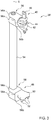
- the swing girder 10 of which an example is shown in Figures 1 and 2 , comprises an upper chord or top-girder 20 of which a top-girder axis L1 extends in a swing girder plane in a swing girder main direction, as well as a lower chord or bottom-girder 22 of which a bottom-girder axis L2 extends parallel to the swing girder main direction in the swing girder plane.
- the top-girder 20 and the bottom-girder 22 are mutually interconnected by a number of connecting tubes 24.
- the swing girder 10 has two fixed rosette couplings 26, 34 which are fixedly connected respectively with a first end of the top-girder 20 and a first end of the bottom-girder 22.
- the swing girder 10 has a swing connector assembly 38 which comprises two pivotable rosette couplings 40, 48 which are connected respectively with a second end of the top-girder 20 and a second end of the bottom-girder 22 in a manner pivotable around a pivoting axis S.
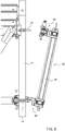
- a lower of the two pivotable rosette couplings 40, 48 is a pivotable girder-support coupling 48 which includes a support plate 50, extending perpendicular to the swing girder plane and the pivoting axis, which is connected with the second end of the bottom-girder 22 in a manner pivotable around the pivoting axis (see Figure 3 ).
- the pivotable girder-support coupling 48 includes at least one positioning pin 52, connected with the support plate 50, which is on a side of the support plate 50 facing away from the top-girder 20.
- the swing connector assembly 38 may further comprise a connecting rod 54 which connects the two pivotable rosette couplings 40, 48 with each other, so that the two pivotable rosette couplings 40, 48 always have the same pivoted position around the pivoting axis S relative to the swing girder plane.
- a connecting rod provides the advantage that the forces exerted on the pivotable rosette couplings and the associated rosettes during mounting and pivoting of the swing girder 10 are distributed better over the two pivotable rosette couplings 40, 48 and the associated rosettes 14.
- an upper of the two second rosette couplings 40, 48 can be a pivotable girder-wedge coupling 40 comprising a body 42 which is connected with a second end of the top-girder 20 in a manner pivotable around a pivoting axis, wherein the pivoting axis S extends in the swing girder plane and extends perpendicular to the top-girder axis L1, wherein the body 42 of the pivotable girder-wedge coupling 40 includes a receiving gap 44 which extends perpendicular to the swing girder plane and the pivoting axis S, and wherein the pivotable girder-wedge coupling 40 includes a wedge 46 which is movably connected with the body 42 of the pivotable girder-wedge coupling 40, wherein the pivotable girder-wedge coupling 40 provides a force-transmitting connection with a standard 12 when the wedge 46 is in a fixation condition.
- a thus-implemented upper pivotable rosette coupling 40 provides for simple assembly. After the pivotable girder-support coupling 48 has been placed by way of the positioning pin 52 on a rosette 14 and rests thereon, the scaffolder can tilt the swing girder 10 into a vertical position (see Figure 6 ) so that the rosette 14 with which the pivotable girder-wedge coupling 40 is to be connected, is received in the receiving gap 44. The scaffolder then only needs to place the wedge 46 in the body 42, so that it extends through a coupling recess 18 of the respective rosette 14.
- the scaffolder can attach, at the end with the two fixed rosette couplings 26, 34, a hanging standard 112 having therein premounted suspension means 120-126 (see Figures 8 and 12 ).
- a lower of the two fixed rosette couplings 26, 34 can be a fixed girder-support coupling 34.
- this fixed girder-support coupling 34 then includes a support plate 36 extending perpendicular to the swing girder plane, which is fixedly connected with a first end of the bottom-girder 22.
- the girder-support coupling 34 then includes at least one positioning pin 38 connected with the support plate, which pin is on the side of the support plate 36 facing away from a top-girder 20.
- an upper of the two fixed rosette couplings 26, 34 is preferably implemented as a fixed girder-wedge coupling 26 which includes a body 28 which is fixedly connected with a first end of the top-girder 20.
- the body 28 has a receiving gap 30 which extends perpendicular to the swing girder plane.
- the fixed girder-wedge coupling 26 includes a wedge 32 which is movably connected with the body 28 of the fixed girder-wedge coupling 26.
- the fixed girder-wedge coupling 26 provides a force-transmitting connection with a standard 12 when the wedge 32 is in a fixation condition.
- a lower rosette 114 is first brought under the support plate 36 and moved up, so that the positioning pin 38 is received in the coupling recess of the lower rosette 114. Then, the scaffolder tilts the hanging standard 112 into a vertical position so that the higher-situated rosette 114 is received in the receiving gap 30 of the fixed girder-wedge coupling 26. Next, the scaffolder only needs to place the wedge 32 in the body 28 so that it extends through the coupling recess of the respective rosette 114. The hanging standard 112 now cannot fall anymore.
- the scaffolder To realize a fixed, force-transmitting connection, the scaffolder only needs to strike the wedge 32 in place with the aid of a hammer and the hanging standard 112 is fixedly connected with the swing girder 10. After these operations, the situation in Figure 8 has been reached.
- the pivotable girder-wedge coupling 40 may, as is clearly visible in Figures 1-3 , comprise a U-shaped bracket 56 which includes two bracket legs 56a and a bracket body 56b.
- the bracket body 56b is fixedly connected with the body 42 of the pivotable girder-wedge coupling 40.
- the pivotable girder-support coupling 48 comprises a U-shaped bracket 58 which includes two bracket legs 58a and a bracket body 58b.
- the bracket body 58b is fixedly connected with the support plate 50 of the pivotable girder-support coupling 48.
- the earlier-mentioned connecting rod 54 interconnects the two U-shaped brackets 56, 58.
- the top-girder 20 and the bottom-girder 22 may each be tubular.
- the second end of the top-girder 20 may then be received between the legs 56a of the U-shaped bracket 56 of the pivotable girder-wedge coupling 40.
- the second end of the bottom-girder 22 may then be received between the legs 58a of the U-shaped bracket 58 of the pivotable girder-support coupling 48.
- the two second ends of the top-girder 20 and the bottom-girder 22 may then be each provided with a hole which forms a passage.
- the swing connector assembly 38 can comprise a hinge pin 60 (see Figure 2 ) which extends along the pivoting axis S through the bracket legs 56a, 58a and the passages of the two second ends to form the pivotable connections between the body 42 of the pivotable girder-wedge coupling 40 and the top-girder 20 and between the support plate 50 of the pivotable girder-support coupling 48 and the bottom-girder 22.
- the hinge pin 60 then forms the pivot of the swing connector assembly 38.
- the hinge pin 60 can extend through the connecting rod 54 which connects the pivotable girder-wedge coupling 40 with the pivotable girder-support coupling 48.
- the connecting rod 54 protects the hinge pin 60 from damage, for example when the swing girders 10 are stacked onto each other for storage.
- the at least one positioning pin 38 connected with the support plate 36 of the fixed girder-support coupling 34, and being on the side of the support plate 36 facing away from the top-girder 20, can comprise three positioning pins 38 (see Figure 1 , in which one of the three positioning pins is visible).
- Three positioning pins 38 provide for a stable positioning of the support plate 36 of the fixed girder-support coupling 34 relative to the rosette 14 on which the support plate 36 rests, in that each positioning pin 38 can be received in an associated coupling recesses 18 or in that, for example, outer positioning pins 38 abut against the circumferential edge of a coupling opening.
- the at least one positioning pin 52 connected with the support plate 50 of the pivotable girder-support coupling 48, and being on the side of the support plate 50 facing away from the top-girder 20, can comprise three positioning pins 52 (see also Figure 1 , in which these three positioning pins 52 are visible).
- Three positioning pins 52 can effect a more defined positioning of the support plate 50 relative to a rosette 14, for instance because each positioning pin 52 extends through a coupling opening 18 of the respective rosette 14. This minimizes the chance of the support plate 50 shifting relative to the rosette 14 during swinging of the swing girder 10, and forces that the support plate 50 exerts on the rosette 14 can be properly transmitted.
- the invention also provides a scaffold system which comprises standards 12, 112 which are provided at regular distances with ring-shaped rosettes 14 which are each provided with coupling recesses 18.
- the scaffold system also comprises ledgers 62 which are provided at the ends with ledger-wedge couplings 64.
- each ledger-wedge coupling comprises a body which is provided with a receiving gap in which a ring-shaped rosette 14 is receivable, and each ledger-wedge coupling 64 includes a wedge which is movably connected with the body of the ledger coupling 64 and which can be inserted through a coupling recess 18 in the ring-shaped rosette 14 and be struck for fixation and for forming a force-transmitting connection between the ledger 62 and the standard 12.
- the scaffold system is characterized according to the invention by swing girders 10 according to the invention, various embodiments of which have been described hereinabove.
- the distance between the top-girder 20 and the bottom-girder 22 of the swing girder 10 substantially corresponds to the distance between two neighboring rosettes 14 or 14' on the standards 12 or 112.
- the scaffold system may further include at least one end girder 72.
- An example of the end girder 72 is shown in detail in Figures 4 and 5 .
- Such an end girder 72 comprises a upper chord or top-girder 74 of which a top-girder axis L3 extends in an end girder plane in an end girder main direction.
- the end girder 72 comprises a lower chord or bottom-girder 76 of which a bottom-girder axis L4 extends parallel to the end girder main direction in the end girder plane.
- the top-girder 74 and the bottom-girder 76 are mutually interconnected by a number of connecting tubes 78.
- the end girder 72 is provided with two end girder wedge couplings 80 which each include a body 82 which is fixedly connected with a first and a second end of the top-girder 74, respectively.
- each body 82 is provided with a receiving gap 84. This receiving gap 84 extends perpendicular to the end girder plane.
- Each end girder wedge coupling 80 furthermore includes a wedge 86 which is movably connected with the body 82 of the end girder wedge coupling 80.
- Each end girder wedge coupling 80 provides a force-transmitting connection with a standard 112 connected therewith when the wedge 86 is in a fixation condition.
- end girder 72 is provided with two end girder support couplings 88 each including a support plate 90 which extends perpendicular to the end girder plane and is fixedly connected with a first and a second end of the bottom-girder 76, respectively.
- Each end girder support coupling 88 includes at least one positioning pin 92 connected with the support plate 90 and which is on a side of the support plate 90 facing away from the top-girder 74.
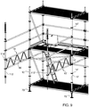
- the scaffold system (see Figure 11 ) comprises, for forming a suspended platform, at least two swing girders 10, 10' according to any one of claims 3-8. That is, swing girders 10, 10' provided at a first end with a fixed girder-support coupling 34 and a fixed girder-wedge coupling 26 and provided at the second end with a pivotable girder-support coupling 48 and a pivotable girder-wedge coupling 40.
- the scaffold system may include at least one end girder 72 as described above and a pair of first standards 12, 12' which are each provided with either suspension means or a base jack 70 for supporting the respective standard 12, 12'.
- Base jacks 70 are known per se from the "Ringscaff erection manual complete" already mentioned above.
- a swing connector assembly 38, 38' of an associated swing girder 10, 10' of the two swing girders may be connected.
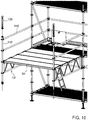
- the scaffold system according to this embodiment may further comprise two hanging standards 112, 112' which are provided with suspension means for attaching the two hanging standards 112, 112' to an overhead construction, such as a bridge, a roof or a beam.
- Each of the two hanging standards 112, 112' is then connected with the fixed girder-support coupling 34, 34' and the fixed girder-wedge coupling 26, 26' of an associated swing girder 10, 10' of the two swing girders 10, 10'.
- each end of the end girder 72 is connected with one of the hanging standards 112, 112'.
- this embodiment of the scaffold system comprises floor parts 94 which rest on and extend transversely to the two swing girders 10, 10'.
- this embodiment of the scaffold system may include a diagonal brace 96 (see Figure 9 ) which connects a rosette 114 of a hanging standard 112 as mentioned with a rosette 14' of standard 12' of the pair of first standards 12, 12' mentioned.
- the length of the diagonal brace 96 is such that in mounted condition of the diagonal brace 96, the main direction of the top-girder 20 of the swing girder 10 that is connected with the respective hanging standard 112 extends perpendicular to the ledger 62 which extends between the two standards 12, 12' of the pair of first standards 12, 12'.
- the suspension means of a hanging standard 112 can comprise a rod 120 which is provided with outer thread and which extends through the hanging standard 112. Further, the suspension means 120-134 in this embodiment comprise a supporting nut 122 which in mounted condition supports an underside of the hanging standard 112. A first lock nut 124 locks the position of the supporting nut 122 on the rod 120. The suspension means further comprise a rotatable turnbuckle 126 which is provided with inner thread by which it is connected with an upper end of the rod 120. With the aid of a second lock nut 128, the position of the rotatable turnbuckle 126 on the rod 120 is locked.
- the suspension means comprise fastening means 130, 132, 134 with which the rotatable turnbuckle 126 is rotatably connected and which are configured for attachment of the rotatable turnbuckle 126 to an overhead structure such as a bridge or roof or beam.
- the fastening means 130-134 can comprise, for example, a suspension eye 130 through which a suspension rod 132 has been passed.
- the suspension rod 132 can be connected using clamps 134 with, for example, an I-beam, as shown in Figure 12 . It will be clear that other types of fastening means for connecting the turnbuckle 126 with an overhead construction are also possible.
- the suspension eye 130, the suspension rod 132 and the clamps 134 as shown merely serve as examples.
- the height of the suspended scaffold platform to be created can be set, so that the platform can be properly horizontally aligned.
- the invention also provides a method of erecting a suspended platform.
- the various steps of the method are shown in the exemplary Figures 6-12 .
- the method comprises:
- All these operations can be carried out without the scaffolder needing to perform any operations for which he has to reach about 0.5 meters below the scaffold floor he is on. It is possible, if so desired, for all these operations to be carried out by a single scaffolder. Moreover, the operations can be carried out relatively quickly because, compared with the known swing girder, there is only half the number of girder-wedge couplings to be positioned, wedges to be placed and struck with a hammer.
- the method can further comprise:
- the safety ledgers 140, 140' can be arranged directly, even before swinging out the swing girder 10, 10', so that before the floor parts 94 are placed, the safety ledgers 140, 140', such as, for example, a safety ledger at knee height and a safety ledger 140 at hip height, are already present.
- the safety ledgers 140, 140' are then directly available for attaching thereto a life line which scaffolders are obliged to work with during erection of a scaffold.
- the method can further comprise:
- connecting the swing connector assembly 38 of the first swing girder 10 with a first 12 of the pair of standards 12, 12' and/or connecting the swing connector assembly 38' of the second swing girder 10' with a second 12' of the pair of standards 12, 12' can comprise:
- connecting the swing connector assembly 38 of a swing girder 10 with a standard 12, 12' can, if desired, be carried out by a single scaffolder and provides a safe and quick way of attaching a swing girder 10, 10' to a standard 12, 12'.
- the activities can all be carried out by a scaffolder from a standing position, which is particularly favorable from an ergonomic viewpoint.
- connecting the end girder 72 with the rosettes 114, 114' of the two hanging standards 112, 112' can comprise:
- This method of placing an end girder 72 is favorable from an ergonomic viewpoint and can be carried out by a single scaffolder.
Landscapes
- Engineering & Computer Science (AREA)
- Architecture (AREA)
- Mechanical Engineering (AREA)
- Civil Engineering (AREA)
- Structural Engineering (AREA)
- Bridges Or Land Bridges (AREA)
Claims (18)
- Schwenkträger (10) zur Verwendung in einem Gerüstsystem vom Ringgerüsttyp, umfassend Ständer (12, 112) mit in regelmäßigen Abständen angeordneten ringförmigen Rosetten (14) mit Kupplungsausnehmungen (18), wobei der Schwenkträger (10) Folgendes umfasst:- einen Oberträger (20), von dem sich eine Oberträgerachse (L1) in einer Schwenkträgerebene in einer Schwenkträgerhauptrichtung erstreckt;- einen Unterträger (22), dessen Unterträgerachse (L2) sich parallel zur Schwenkträgerhauptrichtung in der Schwenkträgerebene erstreckt;- eine Anzahl von Verbindungsrohren (24), die den Oberträger (20) und den Unterträger (22) miteinander verbinden;- zwei feste Rosettenkupplungen (26, 34), die jeweils mit einem ersten Ende des Oberträgers (20) und einem ersten Ende des Unterträgers (22) fest verbunden sind;- eine Schwenkverbinderanordnung (38), die zwei schwenkbare Rosettenkupplungen (40, 48) umfasst, die jeweils mit einem zweiten Ende des Oberträgers (20) und einem zweiten Ende des Unterträgers (22) schwenkbar um eine Schwenkachse (S) verbunden sind;dadurch gekennzeichnet, dass- eine untere der beiden schwenkbaren Rosettenkupplungen (40, 48) eine schwenkbare Trägerstützkupplung (48) ist, die eine sich senkrecht zur Schwenkträgerebene und der Schwenkachse (S) erstreckende Stützplatte (50), die mit dem zweiten Ende des Unterträgers (22) auf um die Schwenkachse (S) schwenkbare Weise verbunden ist, wobei die schwenkbare Trägerstützkupplung (48) wenigstens einen mit der Stützplatte (50) verbundenen Positionierstift (52) aufweist, der sich auf einer dem Oberträger (20) abgewandten Seite der Stützplatte (50) befindet;wobei die Schwenkverbinderanordnung (38) ferner Folgendes umfasst:- eine Verbindungsstange (54), die die beiden schwenkbaren Rosettenkupplungen (40, 48) miteinander verbindet, so dass die beiden schwenkbaren Rosettenkupplungen (40, 48) immer die gleiche geschwenkte Position um die Schwenkachse (S) in Bezug auf Schwenkträgerebene haben.
- Schwenkträger (10) nach Anspruch 1,- wobei eine obere der beiden schwenkbaren Rosettenkupplungen (40, 48) eine schwenkbare Trägerkeilkupplung (40) ist, die einen Körper (42) aufweist, der mit einem zweiten Ende des Oberträgers (20) schwenkbar um eine Schwenkachse verbunden ist, wobei sich die Schwenkachse (S) in der Schwenkträgerebene erstreckt und sich senkrecht zur Oberträgerachse (L1) erstreckt, wobei der Körper (42) der schwenkbaren Trägerkeilkupplung (40) mit einem sich senkrecht zur Schwenkträgerebene und zur Schwenkachse (S) erstreckenden Aufnahmespalt (44) versehen ist, und wobei die schwenkbare Trägerkeilkupplung (40) einen mit dem Körper (42) beweglich verbundenen Keil (46) der schwenkbaren Trägerkeilkupplung (40) aufweist, wobei die schwenkbare Trägerkeilkupplung (40) eine kraftübertragende Verbindung mit einem Ständer (12) bereitstellt, wenn sich der Keil (46) in einem Befestigungszustand befindet.
- Schwenkträger nach Anspruch 2,
wobei eine untere der beiden festen Rosettenkupplungen (26, 34) eine feste Trägerstützkupplung (34) ist, die eine sich senkrecht zur Schwenkträgerebene erstreckende Stützplatte (36) aufweist, die mit einem ersten Ende des Unterträgers (22) fest verbunden ist, wobei die Trägerstützkupplung (34) wenigstens einen Positionierstift (38) aufweist, der mit der Stützplatte verbunden ist, die sich auf der Seite der Stützplatte (36) befindet, die von einem Oberträger (20) abgewandt ist; und
wobei eine obere der beiden festen Rosettenkupplungen (26, 34) eine feste Trägerkeilkupplung (26) ist, die einen Körper (28) aufweist, der mit einem ersten Ende des Oberträgers (20) fest verbunden ist, wobei der Körper (28) mit einem Aufnahmespalt (30) versehen ist, der sich senkrecht zur Schwenkträgerebene erstreckt, wobei die feste Trägerkeilkupplung (26) einen Keil (32) aufweist, der beweglich mit dem Körper (28) der festen Trägerkeilkupplung (26) verbunden ist, wobei die feste Trägerkeilkupplung (26) eine kraftübertragende Verbindung mit einem Ständer (12) bereitstellt, wenn sich der Keil (32) in einem Befestigungszustand befindet. - Schwenkträger nach Anspruch 2 oder 3,
wobei die schwenkbare Trägerkeilkupplung (40) eine U-förmige Halterung (56) mit zwei Halterungsschenkeln (56a) und einem Halterungskörper (56b) umfasst, wobei der Halterungskörper (56b) fest mit dem Körper (42) der schwenkbaren Trägerkeilkupplung (40) verbunden ist,
wobei die schwenkbare Trägerstützkupplung (48) eine U-förmige Halterung (58) mit zwei Halterungsschenkeln (58a) und einem Halterungskörper (58b) umfasst, wobei der Halterungskörper (58b) fest mit der Stützplatte (50) der schwenkbaren Trägerstützkupplung (48) verbunden ist,
wobei die Verbindungsstange (54) die beiden U-förmigen Halterungen (56, 58) miteinander verbindet. - Schwenkträger nach Anspruch 4, wobei der Oberträger (20) und der Unterträger (22) jeweils rohrförmig sind,
wobei das zweite Ende des Oberträgers (20) zwischen den Schenkeln (56a) der U-förmigen Halterung (56) der schwenkbaren Trägerkeilkupplung (40) aufgenommen wird,
wobei das zweite Ende des Unterträgers (22) zwischen den Schenkeln (58a) der U-förmigen Halterung (58) der schwenkbaren Trägerstützkupplung (48) aufgenommen wird,
wobei die beiden zweiten Enden des Oberträgers (20) und des Unterträgers (22) jeweils mit einem Loch versehen sind, das einen Durchgang bildet,
wobei die Schwenkverbinderanordnung (38) einen Gelenkstift (60) umfasst, der sich entlang der Schwenkachse (S) durch die Halterungsschenkel (56a, 58a) und die Durchgänge der beiden zweiten Enden erstreckt, um die schwenkbaren Verbindungen zwischen dem Körper (42) der schwenkbaren Trägerkeilkupplung (40) und des Oberträgers (20) sowie zwischen der Stützplatte (50) der schwenkbaren Trägerstützkupplung (48) und dem Unterträger (22) zu bilden. - Schwenkträger nach Anspruch 5, wobei sich der Gelenkstift (60) durch die Verbindungsstange (54) erstreckt, die die schwenkbare Trägerkeilkupplung (40) mit der schwenkbaren Trägerstützkupplung (48) verbindet.
- Schwenkträger nach Anspruch 3 oder den Ansprüchen 4 bis 6, wenn abhängig von Anspruch 3, wobei der wenigstens eine Positionierstift (38) mit der Stützplatte (36) der festen Trägerstützkupplung (34) verbunden ist, die sich an der dem Oberträger (20) abgewandten Seite der Stützplatte (36) befindet, drei Positionierstifte (38) umfasst.
- Schwenkträger nach einem der Ansprüche 2 bis 7, wobei der wenigstens eine Positionierstift (52) mit der Stützplatte (50) der schwenkbaren Trägerstützkupplung (48) verbunden ist, die sich an der dem Oberträger (20) abgewandten Seite der Stützplatte (50) befindet, drei Positionierstifte (52) umfasst.
- Gerüstsystem, umfassend:- Ständer (12, 112), die in regelmäßigen Abständen mit ringförmigen Rosetten (14) versehen sind, die jeweils mit Kupplungsausnehmungen (18) versehen sind;- Leisten (62), die an den Enden mit Leisten-Keil-Kupplungen (64) vorgesehen sind, wobei jede Leisten-Keil-Kupplung einen Körper aufweist, der mit einem Aufnahmespalt versehen ist, in dem eine ringförmige Rosette (14) aufnehmbar ist, und jede Leisten-Keil-Kupplung (64) einen Keil umfasst, der mit dem Körper der Leistenkupplung (64) beweglich verbunden ist, der durch eine Kupplungsausnehmung (18) in der ringförmigen Rosette (14) eingesetzt werden kann und zur Befestigung und zum Bilden einer kraftübertragenden Verbindung zwischen der Leiste (62) und dem Ständer (12) geschlagen werden kann;Schwenkträger (10) nach einem der vorhergehenden Ansprüche, wobei der Abstand zwischen dem Oberträger (20) und dem Unterträger (22) des Schwenkträgers (10) im Wesentlichen dem Abstand zwischen zwei benachbarten Rosetten (14 oder 14') auf den Ständern (12 oder 112) entspricht.
- Gerüstsystem nach Anspruch 9, das ferner wenigstens einen Endträger (72) aufweist, der Folgendes umfasst:- einen Oberträger (74), von dem sich eine Oberträgerachse (L3) in einer Endträgerebene in einer Endträgerhauptrichtung erstreckt;- einen Unterträger (76), dessen Unterträgerachse (L4) sich parallel zur Endträgerhauptrichtung in der Endträgerebene erstreckt;- eine Anzahl von Verbindungsrohren (78), die den Oberträger (74) und den Unterträger (76) miteinander verbinden;- zwei Endträgerkeilkupplungen (80), die jeweils einen Körper (82) aufweisen, der mit einem ersten und einem zweiten Ende des Oberträgers (74) fest verbunden ist, wobei jeder Körper (82) mit einem Aufnahmespalt versehen ist (84), der sich senkrecht zur Endträgerebene erstreckt, wobei jede Endträgerkeilkupplung (80) einen Keil (86) aufweist, der beweglich mit dem Körper (82) der Endträgerkeilkupplung (80) verbunden ist, wobei jede Endträgerkeilkupplung (80) eine kraftübertragende Verbindung mit einem zugeordneten Ständer (112) bereitstellt, wenn sich der Keil (86) in einem Befestigungszustand befindet;- zwei Endträgerstützkupplungen (88), die jeweils eine sich senkrecht zur Endträgerebene erstreckende Stützplatte (90) aufweisen, die jeweils mit einem ersten und einem zweiten Ende des Unterträgers (76) fest verbunden ist, wobei jede Endträgerstützkupplung (88) wenigstens einen Positionierstift (92) aufweist, der mit der Stützplatte (90) verbunden ist, die sich auf einer Seite der vom Oberträger (74) abgewandten Stützplatte (90) befindet.
- Gerüstsystem nach Anspruch 10, das zum Bilden einer hängenden Bühne wenigstens Folgendes umfasst:- zwei der Schwenkträger (10, 10') nach einem der Ansprüche 4 bis 8;- ein Endträger wie erwähnt (72);- ein Paar erster Ständer (12, 12'), die jeweils entweder mit Aufhängungsmitteln oder einem Fußspindel (70) versehen sind, um den jeweiligen Ständer (12, 12') zu unterstützen, wobei mit jedem Ständer (12, 12') von dem Paar erster Ständer eine Schwenkverbinderanordnung (38, 38') eines zugeordneten Schwenkträgers (10, 10') der beiden Schwenkträger verbunden ist;- zwei hängende Ständer (112, 112'), die mit Aufhängemitteln zum Anbringen der beiden hängenden Ständer (112, 112') an einer Uberkopfkonstruktion wie einer Brücke, einem Dach oder einem Balken versehen sind,wobei jeder der beiden hängenden Ständer (112, 112') mit der festen Trägerstützkupplung (48, 48') und der festen Trägerkeilkupplung (40, 40') eines zugeordneten Schwenkträgers (10, 10') der beiden Schwenkträger verbunden ist,
wobei jedes Ende des Endträgers (72) mit einem der hängenden Ständer (112, 112') verbunden ist; und- Bodenteile (94), die auf den beiden Schwenkträgern (10, 10') aufliegen und sich quer dazu erstrecken. - Gerüstsystem nach Anspruch 11, umfassend:- eine Diagonalstrebe (96), die eine Rosette (114) eines hängenden Ständers (112) mit einer Rosette (14') eines Ständers (12') von dem Paar erster Ständer (12, 12') verbindet, und deren Länge derart ist, dass, im montierten Zustand der Diagonalstrebe (96), sich die Hauptrichtung des Oberträgers (20) des Schwenkträgers (10), der mit dem jeweiligen hängenden Ständer (112) verbunden ist, senkrecht zur Leiste (62) erstreckt, die sich zwischen den beiden Ständern (12, 12') von dem Paar erster Ständer (12, 12') erstreckt.
- Gerüstsystem nach Anspruch 11 oder 12, wobei die Aufhängungsmittel eines hängenden Ständers (112) Folgendes umfassen:- eine Stange (120), die mit einem Außengewinde versehen ist und sich durch den hängenden Ständer (112) erstreckt;- eine Stützmutter (122), die im montierten Zustand eine Unterseite des hängenden Ständers (112) stützt;- eine erste Sicherungsmutter (124), die die Position der Stützmutter (122) auf der Stange (120) sichert;- ein drehbares Spannschloss (126), das mit einem Innengewinde versehen ist und damit mit einem oberen Ende der Stange (120) verbunden ist;- eine zweite Sicherungsmutter (128), die die Position des drehbaren Spannschlosses (126) an der Stange (120) sichert;- Befestigungsmittel (130, 132, 134), mit denen das drehbare Spannschloss (126) drehbar verbunden ist und die zum Anbringen des drehbaren Spannschlosses (126) an einer Überkopfkonstruktion wie einer Brücke oder einem Dach oder einem Balken konfiguriert sind.
- Verfahren zum Errichten einer hängenden Bühne, umfassend:- Bereitstellen eines Gerüstsystems nach der Kombination der Ansprüche 12 und 13;- Stabiles Einrichten des Paars erster Ständer (12, 12') unter Verwendung entweder seiner Aufhängungsmittel oder seiner Fußspindel (70) und Verbinden der ersten Ständers (12, 12') des Paars mit wenigstens einer Leiste (62);- Verbinden der Schwenkverbinderanordnung (38) des ersten Schwenkträgers (10) mit einem ersten (12) von dem Paar erster Ständer (12, 12');- Anbringen eines mit Aufhängungsmitteln versehenen hängenden Ständers (112) an der festen Trägerstützkupplung (34) und der festen Trägerkeilkupplung (26) des ersten Schwenkträgers (10);- Verbinden der Schwenkverbinderanordnung (38') des zweiten Schwenkträgers (10') mit einer zweiten (12') von dem Paar erster Ständer (12, 12');- Anbringen eines mit Aufhängungsmitteln versehenen hängenden Ständers (112) an der festen Trägerstützkupplung (34) und der festen Trägerkeilkupplung (26) des zweiten Schwenkträgers (10);- Herausschwenken des ersten Schwenkträgers (10) und des zweiten Schwenkträgers (10') und Platzieren der Diagonalstrebe (96) zur Befestigung des ersten Schwenkträgers (10) in einer Position, in der sich die Hauptrichtung des Oberträgers (20) des ersten Schwenkträgers (10) senkrecht zu der wenigstens einen Leiste (62) erstreckt, die die zwei Ständer (12, 12') von dem Paar erster Ständer miteinander verbindet;- Platzieren der Bodenteile (94) auf die beiden Schwenkträger (10, 10');- Verbinden des Endträgers (72) mit den Rosetten (114, 114') der beiden hängenden Ständers (112, 112'); und- Anbringen der Aufhängungsmittel der beiden hängenden Ständer (112, 112') an einer Überkopfkonstruktion wie einer Brücke, einem Dach oder einem Balken.
- Verfahren nach Anspruch 14, umfassend:- vor dem Herausschwenken eines ersten und eines zweiten Schwenkträgers (10, 10'), die mit den hängenden Ständern (112, 112') wenigstens eine Sicherheitsleiste (140, 140') mit einer Rosette (114, 114') verbinden, die sich oberhalb der Rosetten (114, 114') befindet, mit denen der jeweilige Schwenkträger (10, 10') mit dem hängenden Ständer (112, 112') verbunden ist;- nach dem Herausschwenken des jeweiligen Schwenkträgers (10, 10') der wenigstens eine Sicherheitsleiste (140) mit einer Rosette (14, 14') der Ständer (12, 12') von dem Paar erster Ständer (12, 12') verbindet, mit dem der jeweilige Schwenkträger (10, 10') verbunden ist.
- Verfahren nach Anspruch 14 oder 15, umfassend:- unmittelbar vor oder unmittelbar nach dem Platzieren des Endträgers (72), Anbringen wenigstens einer Sicherheitsleiste (142), die sich zwischen den beiden hängenden Ständern (112, 112') erstreckt und die mit den Rosetten (114, 114') der hängenden Ständer (112, 112') verbunden ist, die sich über den Rosetten (114, 114') der hängenden Ständer (112, 112') befinden, mit denen der Endträger (72) verbunden ist.
- Verfahren nach einem der Ansprüche 14 bis 16, wobei Verbinden der Schwenkverbinderanordnung (38) des ersten Schwenkträgers (10) mit einem ersten (12) von dem Paar von Ständern (12, 12') und/oder Verbinden der Schwenkverbinderanordnung (38') des zweiten Schwenkträgers (10') mit einem zweiten (12') von dem Paar von Ständers (12, 12') Folgendes umfasst:- Einsetzen des wenigstens einen Positionierstiftes (52) der schwenkbaren Trägerstützkupplung (48) in eine erste Rosette (14, 14') eines jeweiligen Ständers (12, 12');- Kippen des jeweiligen Schwenkträgers (10, 10') in eine Position, in der sich die Schwenkträgerebene im Wesentlichen vertikal erstreckt und eine obere Rosette (14, 14') im Aufnahmespalt (44) der schwenkbaren Trägerkeilkupplung (40) aufgenommen wird;- Einsetzen des Keils (46) der schwenkbaren Trägerkeilkupplung (40) durch eine Kupplungsausnehmung (18) der oberen Rosette (14) und Schlagen des Keils (46) mit Hilfe eines Hammers.
- Verfahren nach einem der Ansprüche 14 bis 17, wobei das Verbinden des Endträgers (72) mit den Rosetten (114, 114') der zwei hängenden Ständer (112, 112') Folgendes umfasst:- Einsetzen der Positionierstifte (92) der beiden Endträgerstützkupplungen (88) in zwei Rosetten (114, 114') der beiden hängenden Ständer (112, 112'), die auf gleicher Höhe positioniert sind;- Kippen des Endträgers (72) in eine Position, in der sich die Endträgerebene im Wesentlichen vertikal erstreckt und die beiden oberen Rosetten (114, 114') der jeweiligen hängenden Ständer (112, 112') in den Aufnahmespalten (84) von zwei zugeordneten Endträgerkeilkupplungen (80) aufgenommen werden;- Einsetzen des Keils (86) jeder Endträgerkeilkupplung (80) durch eine Kupplungsausnehmung (18) der zugeordneten oberen Rosette (114, 114') und Schlagen des Keils (86) mit Hilfe eines Hammers.
Applications Claiming Priority (1)
| Application Number | Priority Date | Filing Date | Title |
|---|---|---|---|
| NL2018515A NL2018515B1 (nl) | 2017-03-15 | 2017-03-15 | Zwenkligger en steigersysteem met een dergelijk zwenkligger en een werkwijze voor het opbouwen van het steigersysteem. |
Publications (2)
| Publication Number | Publication Date |
|---|---|
| EP3375953A1 EP3375953A1 (de) | 2018-09-19 |
| EP3375953B1 true EP3375953B1 (de) | 2019-10-23 |
Family
ID=58639013
Family Applications (1)
| Application Number | Title | Priority Date | Filing Date |
|---|---|---|---|
| EP18162036.0A Active EP3375953B1 (de) | 2017-03-15 | 2018-03-15 | Schwenkbarer träger und gerüstsystem mit einem solchen schwenkbaren träger und verfahren zum errichten eines solchen gerüstsystems |
Country Status (2)
| Country | Link |
|---|---|
| EP (1) | EP3375953B1 (de) |
| NL (1) | NL2018515B1 (de) |
Cited By (1)
| Publication number | Priority date | Publication date | Assignee | Title |
|---|---|---|---|---|
| EP3974598A1 (de) * | 2020-09-23 | 2022-03-30 | Ebner event logistics GmbH | Geländermodul |
Families Citing this family (3)
| Publication number | Priority date | Publication date | Assignee | Title |
|---|---|---|---|---|
| FR3095664B1 (fr) * | 2019-05-03 | 2021-06-18 | Soletanche Freyssinet | Module de jonction pour platelage suspendu |
| CN110805265A (zh) * | 2019-11-08 | 2020-02-18 | 中铁二局集团有限公司 | 一种悬挑外架吊环设置方法 |
| DE202021104665U1 (de) * | 2021-08-30 | 2022-12-01 | Peri Se | Verbindungsscheibe für ein Gerüst |
Family Cites Families (4)
| Publication number | Priority date | Publication date | Assignee | Title |
|---|---|---|---|---|
| US7779599B2 (en) * | 2004-03-31 | 2010-08-24 | Safway Services, Llc | Articulating work platform support system, work platform system, and methods of use thereof |
| KR101004204B1 (ko) * | 2008-10-01 | 2010-12-24 | 김영심 | 강관 비계용 수평재 연결구 |
| CA2740549C (en) * | 2011-05-17 | 2018-09-25 | Athos Construction Products, Inc. | Glued ledger head |
| WO2013066859A1 (en) * | 2011-11-02 | 2013-05-10 | Saferite Platforms, Inc. | Pivoting horizontal and vertical scaffold members and a method of erecting an offset scaffold platform |
-
2017
- 2017-03-15 NL NL2018515A patent/NL2018515B1/nl active
-
2018
- 2018-03-15 EP EP18162036.0A patent/EP3375953B1/de active Active
Non-Patent Citations (1)
| Title |
|---|
| None * |
Cited By (1)
| Publication number | Priority date | Publication date | Assignee | Title |
|---|---|---|---|---|
| EP3974598A1 (de) * | 2020-09-23 | 2022-03-30 | Ebner event logistics GmbH | Geländermodul |
Also Published As
| Publication number | Publication date |
|---|---|
| EP3375953A1 (de) | 2018-09-19 |
| NL2018515B1 (nl) | 2018-09-24 |
Similar Documents
| Publication | Publication Date | Title |
|---|---|---|
| EP3375953B1 (de) | Schwenkbarer träger und gerüstsystem mit einem solchen schwenkbaren träger und verfahren zum errichten eines solchen gerüstsystems | |
| AU2019284413B2 (en) | Individual scaffolding post | |
| US20190390469A1 (en) | Pivoting Horizontal and Vertical Scaffold Members and a Method of Erecting an Offset Scaffold Platform | |
| CA2912199C (en) | Suspended scaffolding structure and connector therefor | |
| CA1073947A (en) | Supporting collar for use with builders scaffolding | |
| AU2012332760A1 (en) | Pivoting horizontal and vertical scaffold members and a method of erecting an offset scaffold platform | |
| US6422339B1 (en) | Wall jack | |
| AU2021424267B2 (en) | Arrangement of scaffolding components | |
| JP6989423B2 (ja) | 荷受けステージ用の支持フレーム | |
| WO2011005087A1 (en) | Forkhead for use in a modular scaffolding system, and method of constructing a scaffold frame using the same | |
| CN1989309A (zh) | 建筑台架配件 | |
| US9765537B2 (en) | Vertical support member for a suspended scaffold assembly, kit for mounting a suspended scaffold assembly, suspended scaffold assembly and method for mounting the same | |
| WO2021194336A1 (en) | Preceding guard rail holder for a scaffolding system | |
| US20230114919A1 (en) | Guard rail assembly for a scaffold | |
| GB2428729A (en) | A scaffold stair unit | |
| GB2417752A (en) | Platform for use in erecting scaffolding | |
| WO2024082268A1 (en) | End integrated advance guardrail for scaffolding systems | |
| CN108316634A (zh) | 一种用于承插型盘扣式钢管支架的铝托梁结构 | |
| CN218521619U (zh) | 一种用于桥梁施工的装配式支架 | |
| WO2023088205A1 (en) | Advance installation guardrail assembly for scaffolding systems | |
| CA1263428A (en) | Drop scaffolding structure and method of erecting same | |
| JPH0654838U (ja) | 仮設足場に用いる建枠の連結部材 | |
| JPH04101455U (ja) | 積上式仮設支持枠の端部支持体 | |
| NZ580246A (en) | Scaffold stair foldable and with platform surface free of side obstruction | |
| AU7310998A (en) | Tiltable tankstand |
Legal Events
| Date | Code | Title | Description |
|---|---|---|---|
| PUAI | Public reference made under article 153(3) epc to a published international application that has entered the european phase |
Free format text: ORIGINAL CODE: 0009012 |
|
| STAA | Information on the status of an ep patent application or granted ep patent |
Free format text: STATUS: THE APPLICATION HAS BEEN PUBLISHED |
|
| AK | Designated contracting states |
Kind code of ref document: A1 Designated state(s): AL AT BE BG CH CY CZ DE DK EE ES FI FR GB GR HR HU IE IS IT LI LT LU LV MC MK MT NL NO PL PT RO RS SE SI SK SM TR |
|
| AX | Request for extension of the european patent |
Extension state: BA ME |
|
| STAA | Information on the status of an ep patent application or granted ep patent |
Free format text: STATUS: REQUEST FOR EXAMINATION WAS MADE |
|
| 17P | Request for examination filed |
Effective date: 20190318 |
|
| RBV | Designated contracting states (corrected) |
Designated state(s): AL AT BE BG CH CY CZ DE DK EE ES FI FR GB GR HR HU IE IS IT LI LT LU LV MC MK MT NL NO PL PT RO RS SE SI SK SM TR |
|
| GRAP | Despatch of communication of intention to grant a patent |
Free format text: ORIGINAL CODE: EPIDOSNIGR1 |
|
| STAA | Information on the status of an ep patent application or granted ep patent |
Free format text: STATUS: GRANT OF PATENT IS INTENDED |
|
| INTG | Intention to grant announced |
Effective date: 20190429 |
|
| GRAS | Grant fee paid |
Free format text: ORIGINAL CODE: EPIDOSNIGR3 |
|
| GRAA | (expected) grant |
Free format text: ORIGINAL CODE: 0009210 |
|
| STAA | Information on the status of an ep patent application or granted ep patent |
Free format text: STATUS: THE PATENT HAS BEEN GRANTED |
|
| AK | Designated contracting states |
Kind code of ref document: B1 Designated state(s): AL AT BE BG CH CY CZ DE DK EE ES FI FR GB GR HR HU IE IS IT LI LT LU LV MC MK MT NL NO PL PT RO RS SE SI SK SM TR |
|
| REG | Reference to a national code |
Ref country code: GB Ref legal event code: FG4D |
|
| REG | Reference to a national code |
Ref country code: CH Ref legal event code: EP |
|
| REG | Reference to a national code |
Ref country code: IE Ref legal event code: FG4D |
|
| REG | Reference to a national code |
Ref country code: DE Ref legal event code: R096 Ref document number: 602018000941 Country of ref document: DE |
|
| REG | Reference to a national code |
Ref country code: AT Ref legal event code: REF Ref document number: 1193783 Country of ref document: AT Kind code of ref document: T Effective date: 20191115 |
|
| REG | Reference to a national code |
Ref country code: NL Ref legal event code: MP Effective date: 20191023 |
|
| REG | Reference to a national code |
Ref country code: LT Ref legal event code: MG4D |
|
| PG25 | Lapsed in a contracting state [announced via postgrant information from national office to epo] |
Ref country code: PL Free format text: LAPSE BECAUSE OF FAILURE TO SUBMIT A TRANSLATION OF THE DESCRIPTION OR TO PAY THE FEE WITHIN THE PRESCRIBED TIME-LIMIT Effective date: 20191023 Ref country code: NL Free format text: LAPSE BECAUSE OF FAILURE TO SUBMIT A TRANSLATION OF THE DESCRIPTION OR TO PAY THE FEE WITHIN THE PRESCRIBED TIME-LIMIT Effective date: 20191023 Ref country code: SE Free format text: LAPSE BECAUSE OF FAILURE TO SUBMIT A TRANSLATION OF THE DESCRIPTION OR TO PAY THE FEE WITHIN THE PRESCRIBED TIME-LIMIT Effective date: 20191023 Ref country code: LV Free format text: LAPSE BECAUSE OF FAILURE TO SUBMIT A TRANSLATION OF THE DESCRIPTION OR TO PAY THE FEE WITHIN THE PRESCRIBED TIME-LIMIT Effective date: 20191023 Ref country code: NO Free format text: LAPSE BECAUSE OF FAILURE TO SUBMIT A TRANSLATION OF THE DESCRIPTION OR TO PAY THE FEE WITHIN THE PRESCRIBED TIME-LIMIT Effective date: 20200123 Ref country code: LT Free format text: LAPSE BECAUSE OF FAILURE TO SUBMIT A TRANSLATION OF THE DESCRIPTION OR TO PAY THE FEE WITHIN THE PRESCRIBED TIME-LIMIT Effective date: 20191023 Ref country code: GR Free format text: LAPSE BECAUSE OF FAILURE TO SUBMIT A TRANSLATION OF THE DESCRIPTION OR TO PAY THE FEE WITHIN THE PRESCRIBED TIME-LIMIT Effective date: 20200124 Ref country code: BG Free format text: LAPSE BECAUSE OF FAILURE TO SUBMIT A TRANSLATION OF THE DESCRIPTION OR TO PAY THE FEE WITHIN THE PRESCRIBED TIME-LIMIT Effective date: 20200123 Ref country code: FI Free format text: LAPSE BECAUSE OF FAILURE TO SUBMIT A TRANSLATION OF THE DESCRIPTION OR TO PAY THE FEE WITHIN THE PRESCRIBED TIME-LIMIT Effective date: 20191023 Ref country code: PT Free format text: LAPSE BECAUSE OF FAILURE TO SUBMIT A TRANSLATION OF THE DESCRIPTION OR TO PAY THE FEE WITHIN THE PRESCRIBED TIME-LIMIT Effective date: 20200224 |
|
| PG25 | Lapsed in a contracting state [announced via postgrant information from national office to epo] |
Ref country code: RS Free format text: LAPSE BECAUSE OF FAILURE TO SUBMIT A TRANSLATION OF THE DESCRIPTION OR TO PAY THE FEE WITHIN THE PRESCRIBED TIME-LIMIT Effective date: 20191023 Ref country code: IS Free format text: LAPSE BECAUSE OF FAILURE TO SUBMIT A TRANSLATION OF THE DESCRIPTION OR TO PAY THE FEE WITHIN THE PRESCRIBED TIME-LIMIT Effective date: 20200224 Ref country code: HR Free format text: LAPSE BECAUSE OF FAILURE TO SUBMIT A TRANSLATION OF THE DESCRIPTION OR TO PAY THE FEE WITHIN THE PRESCRIBED TIME-LIMIT Effective date: 20191023 |
|
| PG25 | Lapsed in a contracting state [announced via postgrant information from national office to epo] |
Ref country code: AL Free format text: LAPSE BECAUSE OF FAILURE TO SUBMIT A TRANSLATION OF THE DESCRIPTION OR TO PAY THE FEE WITHIN THE PRESCRIBED TIME-LIMIT Effective date: 20191023 |
|
| REG | Reference to a national code |
Ref country code: DE Ref legal event code: R097 Ref document number: 602018000941 Country of ref document: DE |
|
| PG2D | Information on lapse in contracting state deleted |
Ref country code: IS |
|
| PG25 | Lapsed in a contracting state [announced via postgrant information from national office to epo] |
Ref country code: DK Free format text: LAPSE BECAUSE OF FAILURE TO SUBMIT A TRANSLATION OF THE DESCRIPTION OR TO PAY THE FEE WITHIN THE PRESCRIBED TIME-LIMIT Effective date: 20191023 Ref country code: EE Free format text: LAPSE BECAUSE OF FAILURE TO SUBMIT A TRANSLATION OF THE DESCRIPTION OR TO PAY THE FEE WITHIN THE PRESCRIBED TIME-LIMIT Effective date: 20191023 Ref country code: ES Free format text: LAPSE BECAUSE OF FAILURE TO SUBMIT A TRANSLATION OF THE DESCRIPTION OR TO PAY THE FEE WITHIN THE PRESCRIBED TIME-LIMIT Effective date: 20191023 Ref country code: RO Free format text: LAPSE BECAUSE OF FAILURE TO SUBMIT A TRANSLATION OF THE DESCRIPTION OR TO PAY THE FEE WITHIN THE PRESCRIBED TIME-LIMIT Effective date: 20191023 Ref country code: CZ Free format text: LAPSE BECAUSE OF FAILURE TO SUBMIT A TRANSLATION OF THE DESCRIPTION OR TO PAY THE FEE WITHIN THE PRESCRIBED TIME-LIMIT Effective date: 20191023 Ref country code: IS Free format text: LAPSE BECAUSE OF FAILURE TO SUBMIT A TRANSLATION OF THE DESCRIPTION OR TO PAY THE FEE WITHIN THE PRESCRIBED TIME-LIMIT Effective date: 20200223 |
|
| REG | Reference to a national code |
Ref country code: AT Ref legal event code: MK05 Ref document number: 1193783 Country of ref document: AT Kind code of ref document: T Effective date: 20191023 |
|
| PLBE | No opposition filed within time limit |
Free format text: ORIGINAL CODE: 0009261 |
|
| STAA | Information on the status of an ep patent application or granted ep patent |
Free format text: STATUS: NO OPPOSITION FILED WITHIN TIME LIMIT |
|
| PG25 | Lapsed in a contracting state [announced via postgrant information from national office to epo] |
Ref country code: IT Free format text: LAPSE BECAUSE OF FAILURE TO SUBMIT A TRANSLATION OF THE DESCRIPTION OR TO PAY THE FEE WITHIN THE PRESCRIBED TIME-LIMIT Effective date: 20191023 Ref country code: SK Free format text: LAPSE BECAUSE OF FAILURE TO SUBMIT A TRANSLATION OF THE DESCRIPTION OR TO PAY THE FEE WITHIN THE PRESCRIBED TIME-LIMIT Effective date: 20191023 Ref country code: SM Free format text: LAPSE BECAUSE OF FAILURE TO SUBMIT A TRANSLATION OF THE DESCRIPTION OR TO PAY THE FEE WITHIN THE PRESCRIBED TIME-LIMIT Effective date: 20191023 |
|
| 26N | No opposition filed |
Effective date: 20200724 |
|
| PG25 | Lapsed in a contracting state [announced via postgrant information from national office to epo] |
Ref country code: MC Free format text: LAPSE BECAUSE OF FAILURE TO SUBMIT A TRANSLATION OF THE DESCRIPTION OR TO PAY THE FEE WITHIN THE PRESCRIBED TIME-LIMIT Effective date: 20191023 |
|
| PG25 | Lapsed in a contracting state [announced via postgrant information from national office to epo] |
Ref country code: SI Free format text: LAPSE BECAUSE OF FAILURE TO SUBMIT A TRANSLATION OF THE DESCRIPTION OR TO PAY THE FEE WITHIN THE PRESCRIBED TIME-LIMIT Effective date: 20191023 Ref country code: AT Free format text: LAPSE BECAUSE OF FAILURE TO SUBMIT A TRANSLATION OF THE DESCRIPTION OR TO PAY THE FEE WITHIN THE PRESCRIBED TIME-LIMIT Effective date: 20191023 |
|
| REG | Reference to a national code |
Ref country code: BE Ref legal event code: MM Effective date: 20200331 |
|
| PG25 | Lapsed in a contracting state [announced via postgrant information from national office to epo] |
Ref country code: LU Free format text: LAPSE BECAUSE OF NON-PAYMENT OF DUE FEES Effective date: 20200315 |
|
| PG25 | Lapsed in a contracting state [announced via postgrant information from national office to epo] |
Ref country code: IE Free format text: LAPSE BECAUSE OF NON-PAYMENT OF DUE FEES Effective date: 20200315 |
|
| PG25 | Lapsed in a contracting state [announced via postgrant information from national office to epo] |
Ref country code: BE Free format text: LAPSE BECAUSE OF NON-PAYMENT OF DUE FEES Effective date: 20200331 |
|
| REG | Reference to a national code |
Ref country code: CH Ref legal event code: PL |
|
| PG25 | Lapsed in a contracting state [announced via postgrant information from national office to epo] |
Ref country code: CH Free format text: LAPSE BECAUSE OF NON-PAYMENT OF DUE FEES Effective date: 20210331 Ref country code: LI Free format text: LAPSE BECAUSE OF NON-PAYMENT OF DUE FEES Effective date: 20210331 |
|
| PG25 | Lapsed in a contracting state [announced via postgrant information from national office to epo] |
Ref country code: TR Free format text: LAPSE BECAUSE OF FAILURE TO SUBMIT A TRANSLATION OF THE DESCRIPTION OR TO PAY THE FEE WITHIN THE PRESCRIBED TIME-LIMIT Effective date: 20191023 Ref country code: MT Free format text: LAPSE BECAUSE OF FAILURE TO SUBMIT A TRANSLATION OF THE DESCRIPTION OR TO PAY THE FEE WITHIN THE PRESCRIBED TIME-LIMIT Effective date: 20191023 Ref country code: CY Free format text: LAPSE BECAUSE OF FAILURE TO SUBMIT A TRANSLATION OF THE DESCRIPTION OR TO PAY THE FEE WITHIN THE PRESCRIBED TIME-LIMIT Effective date: 20191023 |
|
| PG25 | Lapsed in a contracting state [announced via postgrant information from national office to epo] |
Ref country code: MK Free format text: LAPSE BECAUSE OF FAILURE TO SUBMIT A TRANSLATION OF THE DESCRIPTION OR TO PAY THE FEE WITHIN THE PRESCRIBED TIME-LIMIT Effective date: 20191023 |
|
| PGFP | Annual fee paid to national office [announced via postgrant information from national office to epo] |
Ref country code: DE Payment date: 20240320 Year of fee payment: 7 Ref country code: GB Payment date: 20240320 Year of fee payment: 7 |
|
| PGFP | Annual fee paid to national office [announced via postgrant information from national office to epo] |
Ref country code: FR Payment date: 20240328 Year of fee payment: 7 |