EP3374777B1 - Batteriebetriebenes relaistestgerät - Google Patents
Batteriebetriebenes relaistestgerät Download PDFInfo
- Publication number
- EP3374777B1 EP3374777B1 EP16784898.5A EP16784898A EP3374777B1 EP 3374777 B1 EP3374777 B1 EP 3374777B1 EP 16784898 A EP16784898 A EP 16784898A EP 3374777 B1 EP3374777 B1 EP 3374777B1
- Authority
- EP
- European Patent Office
- Prior art keywords
- signal
- test device
- pulses
- pause times
- signal generator
- Prior art date
- Legal status (The legal status is an assumption and is not a legal conclusion. Google has not performed a legal analysis and makes no representation as to the accuracy of the status listed.)
- Active
Links
Images

Classifications
-
- G—PHYSICS
- G01—MEASURING; TESTING
- G01R—MEASURING ELECTRIC VARIABLES; MEASURING MAGNETIC VARIABLES
- G01R31/00—Arrangements for testing electric properties; Arrangements for locating electric faults; Arrangements for electrical testing characterised by what is being tested not provided for elsewhere
- G01R31/327—Testing of circuit interrupters, switches or circuit-breakers
- G01R31/3277—Testing of circuit interrupters, switches or circuit-breakers of low voltage devices, e.g. domestic or industrial devices, such as motor protections, relays, rotation switches
- G01R31/3278—Testing of circuit interrupters, switches or circuit-breakers of low voltage devices, e.g. domestic or industrial devices, such as motor protections, relays, rotation switches of relays, solenoids or reed switches
-
- G—PHYSICS
- G01—MEASURING; TESTING
- G01R—MEASURING ELECTRIC VARIABLES; MEASURING MAGNETIC VARIABLES
- G01R31/00—Arrangements for testing electric properties; Arrangements for locating electric faults; Arrangements for electrical testing characterised by what is being tested not provided for elsewhere
- G01R31/327—Testing of circuit interrupters, switches or circuit-breakers
-
- G—PHYSICS
- G01—MEASURING; TESTING
- G01R—MEASURING ELECTRIC VARIABLES; MEASURING MAGNETIC VARIABLES
- G01R33/00—Arrangements or instruments for measuring magnetic variables
- G01R33/20—Arrangements or instruments for measuring magnetic variables involving magnetic resonance
- G01R33/44—Arrangements or instruments for measuring magnetic variables involving magnetic resonance using nuclear magnetic resonance [NMR]
- G01R33/48—NMR imaging systems
- G01R33/4828—Resolving the MR signals of different chemical species, e.g. water-fat imaging
-
- G—PHYSICS
- G01—MEASURING; TESTING
- G01R—MEASURING ELECTRIC VARIABLES; MEASURING MAGNETIC VARIABLES
- G01R33/00—Arrangements or instruments for measuring magnetic variables
- G01R33/20—Arrangements or instruments for measuring magnetic variables involving magnetic resonance
- G01R33/44—Arrangements or instruments for measuring magnetic variables involving magnetic resonance using nuclear magnetic resonance [NMR]
- G01R33/48—NMR imaging systems
- G01R33/50—NMR imaging systems based on the determination of relaxation times, e.g. T1 measurement by IR sequences; T2 measurement by multiple-echo sequences
-
- G—PHYSICS
- G01—MEASURING; TESTING
- G01R—MEASURING ELECTRIC VARIABLES; MEASURING MAGNETIC VARIABLES
- G01R33/00—Arrangements or instruments for measuring magnetic variables
- G01R33/20—Arrangements or instruments for measuring magnetic variables involving magnetic resonance
- G01R33/44—Arrangements or instruments for measuring magnetic variables involving magnetic resonance using nuclear magnetic resonance [NMR]
- G01R33/48—NMR imaging systems
- G01R33/54—Signal processing systems, e.g. using pulse sequences ; Generation or control of pulse sequences; Operator console
- G01R33/543—Control of the operation of the MR system, e.g. setting of acquisition parameters prior to or during MR data acquisition, dynamic shimming, use of one or more scout images for scan plane prescription
-
- G—PHYSICS
- G01—MEASURING; TESTING
- G01R—MEASURING ELECTRIC VARIABLES; MEASURING MAGNETIC VARIABLES
- G01R33/00—Arrangements or instruments for measuring magnetic variables
- G01R33/20—Arrangements or instruments for measuring magnetic variables involving magnetic resonance
- G01R33/44—Arrangements or instruments for measuring magnetic variables involving magnetic resonance using nuclear magnetic resonance [NMR]
- G01R33/48—NMR imaging systems
- G01R33/54—Signal processing systems, e.g. using pulse sequences ; Generation or control of pulse sequences; Operator console
- G01R33/56—Image enhancement or correction, e.g. subtraction or averaging techniques, e.g. improvement of signal-to-noise ratio and resolution
- G01R33/5608—Data processing and visualization specially adapted for MR, e.g. for feature analysis and pattern recognition on the basis of measured MR data, segmentation of measured MR data, edge contour detection on the basis of measured MR data, for enhancing measured MR data in terms of signal-to-noise ratio by means of noise filtering or apodization, for enhancing measured MR data in terms of resolution by means for deblurring, windowing, zero filling, or generation of gray-scaled images, colour-coded images or images displaying vectors instead of pixels
-
- A—HUMAN NECESSITIES
- A61—MEDICAL OR VETERINARY SCIENCE; HYGIENE
- A61B—DIAGNOSIS; SURGERY; IDENTIFICATION
- A61B90/00—Instruments, implements or accessories specially adapted for surgery or diagnosis and not covered by any of the groups A61B1/00 - A61B50/00, e.g. for luxation treatment or for protecting wound edges
- A61B90/36—Image-producing devices or illumination devices not otherwise provided for
- A61B90/37—Surgical systems with images on a monitor during operation
- A61B2090/374—NMR or MRI
-
- A—HUMAN NECESSITIES
- A61—MEDICAL OR VETERINARY SCIENCE; HYGIENE
- A61B—DIAGNOSIS; SURGERY; IDENTIFICATION
- A61B2503/00—Evaluating a particular growth phase or type of persons or animals
- A61B2503/04—Babies, e.g. for SIDS detection
-
- A—HUMAN NECESSITIES
- A61—MEDICAL OR VETERINARY SCIENCE; HYGIENE
- A61B—DIAGNOSIS; SURGERY; IDENTIFICATION
- A61B5/00—Measuring for diagnostic purposes; Identification of persons
- A61B5/05—Detecting, measuring or recording for diagnosis by means of electric currents or magnetic fields; Measuring using microwaves or radio waves
- A61B5/0515—Magnetic particle imaging
Definitions
- the present invention relates to a method and a test device for testing a protective relay, in which a signal is generated in the test device, the signal is applied to the protective relay, and an adapter located in the test device is supplied with a supply voltage from a secondary battery, wherein the adapter device supplied by means of an intermediate voltage, a signal generator which generates a signal, wherein the shape of the signal is determined by a control unit.
- a test arrangement of the test devices will be described.
- protection relays are used to monitor the system (primary system). In order to handle the real, primary currents and voltages better, the currents are transformed by current transformers and the voltages through voltage transformers into smaller, easier-to-handle secondary quantities, which are processed in the protective relay. Nevertheless, the protection relay is aware of the state of the primary current and voltage quantities at all times. Depending on the criteria, protection relays can determine whether there is a fault in the primary system and then, depending on the fault, issue a switch-off command to one or more circuit breakers immediately or after a defined delay time in order to end the fault condition in the system. If possible, several protection relays work together so that faults are switched off quickly, safely and selectively. Selective means that as far as possible only the part of the energy transmission network in which the error has occurred is switched off so that as many other parts of the energy transmission network can continue to operate undisturbed.
- a protection relay One function of a protection relay is overcurrent protection. Depending on the magnitude of the current, the switch-off command is issued at different speeds when the rated current is exceeded. For safety reasons, it is necessary or required to check safety devices of an electrical power transmission network, such as the protective relay, at regular intervals for correct function.
- the test of a protective relay with overcurrent-time protection function can, for example, be done by feeding into the protective relay a test current, one- or three-phase, and observing the reaction of the protective relay.
- Test equipment for testing protection relays are also called "relay testing devices".
- the protective relay is for this purpose separated from the electrical power transmission network and connected directly to a test device and secondary quantities are fed via a current transformer.
- direct tests of primary sizes are also possible. It is checked whether the protection relay correctly does not trip at currents below a current threshold, for example at nominal currents, and how fast the protection relay triggers at different fault conditions. In the case of overcurrent time protection, it is customary to switch off faster with increasing current level.
- the test device is provided with an input which is connected to the circuit breaker output of the protective relay and is designed to register when the protective relay switches, that would switch the circuit breaker. If you now want to determine the signal threshold at which a protective relay responds, a small current can be increased continuously until the protective relay reacts. Such a test can take more than a few seconds, or even take minutes.
- the US 3,894,284 A discloses a portable relay tester that utilizes an accumulator wherein the voltage of the accumulator is transformed to an appropriate supply voltage.
- a relay test device can be seen, which is powered by a battery with energy. A voltage transformation takes place via an intermediate capacitor.
- the US 4,351,013 shows a protective relay, which has an integrated test function.
- the aim of the present invention is therefore to provide a test device which is more efficient and easier to handle and reduces the disadvantages described above.
- a fitting device located in the test device is supplied with a supply voltage from an accumulator and the adapter device supplies by means of an intermediate voltage a signal generator which generates a signal, the shape of the Determined signal from a control unit and the result of the control unit is processed by a digital / analog converter for the realization of the signal and the digital / analog converter drives the signal generator.
- test device is connected to a protective relay and has a signal output, via which a signal is output to a signal input of the protective relay, and has a reaction input, which is connected to the switching output of the protective relay, wherein a digital / analog converter is present, which processes the result of the control unit for the realization of the signal and drives the signal generator.
- an accumulator makes it possible to dispense with fuel-supplied generators.
- an accumulator usually provides a very high voltage, whereas the test device requires a high current.
- an adaptation device is used according to the invention, which serves, for example, to translate the supply voltage of the accumulator to small voltages and to translate the small currents of the accumulator to high currents. This is advantageous because the signal generator usually requires high currents, but of course a low supply voltage of the accumulator can be transformed into a high intermediate voltage and a high current supplied by the accumulator can be transformed into a low current.
- the signal may represent, for example, a current or a voltage, the method is also applicable to other signals.
- the signal generator may include a voltage source and / or a power source.
- the adapter may include a step-up converter and / or a step-down converter.
- At least part of the adaptation device and / or at least part of the signal generator can be deactivated as required by means of an emergency shutdown.
- the adjustment device advantageously existing power electronics, selectively deactivated, with a redundancy of the deactivated parts ensures the necessary security. This redundancy can be achieved, for example, by deactivating the adapter and the signal generator.
- the adapter may need to operate at high clock frequencies, so additional low-pass filters are advantageous for suppressing noise.
- the form of the signal is determined by a control unit, wherein the result of the control unit is processed by a digital / analogue converter for the realization of the signal.
- the digital / analog converter continues to drive the signal generator.
- the protection relay can switch after the signal reaches a signal threshold within a response time, wherein the height of the signal is determined by the test device when the signal threshold is reached.
- the signal generator can output the signal as pulses with pause times, wherein the pulses of the signal and the pause times alternate over time, in the pause times the height of the signal is lowered and at least one pulse has a higher amplitude than at least one of the preceding pulses.
- the accumulator In operation, the accumulator is very heavily loaded in a short time, especially when ramps have to be driven to determine signal thresholds as described above, and the test takes a relatively long time.
- the signal generator In order to keep the load of the accumulator low, the signal generator outputs the signal as pulses with pause times, wherein the amplitudes of the pulses can be monotonically increasing, in any case must have an increasing tendency to reach a switching threshold. Since the signal is generated in the form of individual pulses, the average energy required is reduced and the accumulator is spared. This allows, despite the required for the test, adapted to the electrical energy transmission network, voltages and current quantities, the use of smaller, more compact batteries, which is important for a portable device, for example.
- the respective pulse durations reach the response time of the protection relay in order to be able to check the correct function of the protection relay.
- the duration of the pauses to be chosen depends on the energy of the pulses, i. from the amplitude and again the pulse duration.
- the response time of the protection relay tends to be lower for high signals to be switched than for lower signals.
- test device can have a first number of signal outputs which generate the first number of signals.
- test device may have a second number of reaction inputs.
- three current outputs and three voltage outputs can be provided on the test device in order to be able to image the signals of a three-phase branch in the energy network.
- This allows a three-phase network to be simulated and a three-phase protective relay to be checked.
- the signals of the individual phases do not necessarily have the same amplitude.
- a phase shift of 120 ° between the phases is common, but can also deviate completely in the event of a fault.
- two reaction inputs can also be present at the test device in order to be able to detect various reactions of the protective relay, such as triggering or excitation.
- An excitation may mean that a signal threshold has been exceeded briefly, but not long enough to trigger.
- the amplitudes of the pulses of the signal may increase over time by one, preferably fixed, signal difference.
- the signal can be piecewise approximated to the signal threshold and, for example, an overcurrent time protection can be checked.
- the pause times may be variable and depend on the amplitude of the pulses of the signal at the current time.
- a pulse threshold at which the pause times are increased by a factor k.
- the break times are influenced, for example, by multiple pulse thresholds, or are variable in another way. With variable pause times can be achieved that the accumulator from larger currents more time for the "recovery" is available. Likewise, the signal difference could be made variable.
- the signal can be advantageously lowered in the pause times to a value less than 1% of the previous pulse, preferably to zero. This minimizes the average power consumption from the accumulator.
- the accumulator may have an energy density of at least 500 J / g.
- the accumulator or a part thereof can be constructed on a lithium-ion or lithium-polymer base.
- test device can be made portable, wherein the low weight by using a rechargeable battery for use in the field is particularly advantageous.
- a protective relay 2 is connected via the signal input SE and the switching output A to the electrical power supply network 6.
- the electrical energy supply network 6 can also be a line section or a line branch of a larger supply network.
- An optionally present signal converter 1 measures a preliminary signal S n (primary variable) - if the signal is represented by a current, the signal converter 1 is usually designed as a current transformer or current sensor - the power supply network 6 and transforms this into a signal S (secondary size), which is supplied to the protective relay 2 via the signal input SE. For example, in low-voltage networks, it is also possible to supply the preliminary signal S n directly to the protection relay.
- the protective relay 2 is designed so that it switches the switching output A, and thus the associated circuit breaker 3 of the electrical energy supply network 6 opens as soon as a certain, preset signal threshold S S is exceeded for a fixed period of time.
- the electrical circuit of the power supply network 6 (or the respective network segment) is interrupted, which, for example, in the electrical energy supply network 6 ensures protection against overcurrents.
- the protective relay 2 is disconnected from the power supply network 6 for a functional test and connected to a test device 4, as in FIG Fig.2 shown.
- the test facility 4 has a signal output SA and a reaction input R.
- the connection from the protective relay 2 to the signal converter 1 (or if no current transformer is present the connection to the power grid 6) and the circuit breaker 3 is interrupted and the signal output SA of the test device 4 with the signal input SE of the protective relay 2, and the switching output A. of the protective relay 2 connected to the reaction input R of the test device 4.
- the test device 4 in turn is supplied by a battery 5, which is preferably integrated in the test device 4, via a supply input V with a supply voltage U V.
- a signal S from the tester 4 to the protective relay 2 If the protection includes, for example, an overcurrent time protection, the protective relay 2 switches within a response time t A , after the signal S to be determined signal threshold S s has reached. From the test device 4, the height, that is, the amplitude, of the signal S is determined upon reaching the protective relay 2 responds.
- an evaluation unit 7 is provided in the test device 4, which is connected to the reaction input R and a switching pulse of the protective relay 2, which is output at the switching output A detected.
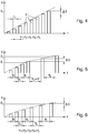
- a signal generator G outputs the signal S as pulses P with pause times T 1 , T 2 , T 3 , T 4 , T 5 at the signal output SA, the pulses P of the signal S and pause times T 1 , T 2 , T 3 , T 4 , T 5 alternate over time t ( Figure 3 ).
- the amplitude of the signal S is lowered to a low value, for example 1% of the previous amplitude or even zero.
- At least one pulse P has a higher amplitude than at least one of the previous pulses P to map a rising signal S, as in FIG Figure 4 exemplified.
- response time t A of the protective relay 2 is determined by the test device 4, preferably in the evaluation unit 7, is also particularly advantageous.
- the response time t A of the protective relay 2 thus describes the time from reaching the signal threshold S S by the signal S to the switching of the reaction output R.
- An adaptation device X located in the test device 4 can convert the supply voltage U v of the accumulator 5 into an intermediate voltage U X , which in turn supplies the signal generator G, as well as in FIG Figure 3 shown.
- the matching device X can serve to convert high voltages into low voltages and low currents into high currents, or vice versa.
- This adaptation device X may include a step-up converter and / or a step-down converter.
- adaptation device X and / or of the signal generator G can be deactivated as required by means of an emergency shutdown N.
- This part of the adaptation device X may, for example, comprise power electronics, which is part of a converter circuit. Since high currents are difficult to separate cleanly, one possibility is to realize an emergency stop N, the deliberate deactivation of (redundant) circuit parts, such as e.g. the power electronics.
- the test device 4, or the signal generator G may include a voltage source and / or a current source and generate a signal S as a voltage or current.
- the shape of the signal S can be calculated by a control unit E, wherein the result of the control unit E is processed by a digital / analog converter DAC for the realization of the signal S and the digital / analog converter DAC drives the signal generator G.
- an input unit 8 connected to the control unit E can be provided in the test device 4, via which e.g. a specific test to be performed can be set.
- the control unit E and the digital / analog converter DAC can be located in the signal generator G.
- the signal generator G n> 1 may have signal outputs which generate n signals S n in order to test a protective relay 2 of a multi-phase network for all n phases simultaneously.
- n 3, whereby a three-phase network can be simulated.
- a three-phase protective relay 2 can be checked.
- the n signals S n need not necessarily be the same.
- test device 4 can have a second number of reaction inputs R to detect different reactions of the protective relay 2, such as a triggering or an excitation.
- a signal S is generated at a certain level (amplitude) over a pulse duration t S and lowered after expiration of the pulse duration t S for a pause time T 1 , T 2 , T 3 , T 4 , T 5 .
- Pause times T 1 , T 2 , T 3 , T 4 , T 5 in the order of 500 ms to 1 s are the rule here.
- the length of the pulse duration t S must be at least as large as the response time t A of the protective relay 2, since otherwise the correct function of the protective relay 2 can not be tested. At least one pulse duration t S of 10 ms is required in most cases, usual pulse durations t S are approximately 30 ms, but pulse durations in the second range are also possible.
- the decisive factor here is the response time t A of the protective relay 2, which in turn depends on the height of the signal to be switched. A higher current usually needs faster, ie with a shorter response time t A , than a lower current.
- the pulse duration t S is in the FIGS. 3 to 5 as a constant, but may also, for example, depending on the height of the signal S, vary. This can be used, for example, to keep the energy of a pulse P low by reducing the pulse durations t S with increasing amplitude.
- the signal is increased by the signal difference ⁇ S for a further pulse duration t S , whereupon again a pause time T 1 , T 2 , T 3 , T 4 , T 5 follows. This advantageously takes place until the protective relay 2 responds or triggers.
- the signal difference ⁇ S is always constant and positive.
- the signal difference .DELTA.S is variable, or in sections negative or zero, which may for example depend on the current level of the signal S.
- at least one pulse P must have a higher amplitude than at least one of the preceding pulses P, unless the amplitude of the first pulse P of the signal S reaches the signal threshold S S. In this case, the protective relay 2 switches immediately.
- the pause times T 1 , T 2 , T 3 , T 4 , T 5 of the signal S that persist between the individual pulses P of the signal S may always have the same length but may also depend on the current amplitude of the signal S or another factor.
- FIG 3 an exemplary course of a signal S over the time t is shown.
- the envelope of the signal S interrupted by pause times T 1 , T 2 , T 3 , T 4 , T 5 is shown in broken lines and indicates the rising signal S, the pause times T 1 , T 2 , T 3 , T 4 in this example , T 5 are constant and the height of the successive pulses P of the signal S increases linearly at a constant signal difference ⁇ S.
- the height of the signal S is reduced as mentioned.
- the signal S in the pauses T 1 , T 2 , T 3 , T 4 , T 5 can be set to a value less than 1% of the previous pulse P, or even to zero, as in the Fig.3-5 shown, which can extend the life of the accumulator 5.
- the accumulator 5 can have an energy density of at least 500 J / g.
- the pause times T 1 , T 2 , T 3 , T 4 , T 5 increase continuously with increasing height of the signal S.
- the pause times T 1 , T 2 , T 3 , T 4 , T 5 can thus be strictly monotonically increasing from pulse P to pulse P, resulting in an envelope shown in dashed lines with the slope reduced over time t for the signal S.
- This embodiment is in Fig. 5 also shown with constant signal difference .DELTA.S.
- the test device 4 can be made portable by the low weight by using a rechargeable battery 5, which is particularly advantageous for use in the field.
Landscapes
- Physics & Mathematics (AREA)
- General Physics & Mathematics (AREA)
- High Energy & Nuclear Physics (AREA)
- Condensed Matter Physics & Semiconductors (AREA)
- Engineering & Computer Science (AREA)
- Signal Processing (AREA)
- Computer Vision & Pattern Recognition (AREA)
- Health & Medical Sciences (AREA)
- General Health & Medical Sciences (AREA)
- Nuclear Medicine, Radiotherapy & Molecular Imaging (AREA)
- Radiology & Medical Imaging (AREA)
- Artificial Intelligence (AREA)
- Testing Electric Properties And Detecting Electric Faults (AREA)
- Emergency Protection Circuit Devices (AREA)
Priority Applications (1)
| Application Number | Priority Date | Filing Date | Title |
|---|---|---|---|
| PL16784898T PL3374777T3 (pl) | 2015-11-10 | 2016-10-21 | Zasilane bateryjnie urządzenie do testowania przekaźnika |
Applications Claiming Priority (2)
| Application Number | Priority Date | Filing Date | Title |
|---|---|---|---|
| ATA50957/2015A AT517906B1 (de) | 2015-11-10 | 2015-11-10 | Batteriebetriebenes Relaistestgerät |
| PCT/EP2016/075343 WO2017080786A1 (de) | 2015-11-10 | 2016-10-21 | Batteriebetriebenes relaistestgerät 2 |
Publications (2)
| Publication Number | Publication Date |
|---|---|
| EP3374777A1 EP3374777A1 (de) | 2018-09-19 |
| EP3374777B1 true EP3374777B1 (de) | 2019-09-04 |
Family
ID=57184456
Family Applications (1)
| Application Number | Title | Priority Date | Filing Date |
|---|---|---|---|
| EP16784898.5A Active EP3374777B1 (de) | 2015-11-10 | 2016-10-21 | Batteriebetriebenes relaistestgerät |
Country Status (14)
| Country | Link |
|---|---|
| US (1) | US10746801B2 (pl) |
| EP (1) | EP3374777B1 (pl) |
| KR (1) | KR102119330B1 (pl) |
| CN (1) | CN108351382A (pl) |
| AT (1) | AT517906B1 (pl) |
| AU (1) | AU2016351691B2 (pl) |
| BR (1) | BR112018009290B1 (pl) |
| CA (1) | CA3004923C (pl) |
| ES (1) | ES2751556T3 (pl) |
| MX (1) | MX379724B (pl) |
| PL (1) | PL3374777T3 (pl) |
| RU (1) | RU2702993C1 (pl) |
| WO (1) | WO2017080786A1 (pl) |
| ZA (1) | ZA201803695B (pl) |
Families Citing this family (5)
| Publication number | Priority date | Publication date | Assignee | Title |
|---|---|---|---|---|
| WO2020209523A1 (ko) * | 2019-04-10 | 2020-10-15 | 엘에스일렉트릭(주) | 보호계전기 검사 장치 |
| CN112925250B (zh) * | 2021-03-05 | 2022-06-21 | 广州市微生物研究所有限公司 | 等离子体空气净化器电参数老化试验控制方法及控制电路 |
| CN116106731B (zh) * | 2022-09-08 | 2023-12-29 | 深圳深爱半导体股份有限公司 | 继电器测试装置 |
| KR20240043539A (ko) | 2022-09-27 | 2024-04-03 | 한국전기안전공사 | 활선 감지 장치의 이상 여부를 진단하는 휴대용 안전장구 시험 장치 및 이의 시험 방법 |
| SE546379C2 (en) * | 2023-05-23 | 2024-10-22 | Megger Sweden Ab | Method and device for testing protection relays |
Family Cites Families (28)
| Publication number | Priority date | Publication date | Assignee | Title |
|---|---|---|---|---|
| SU393701A1 (ru) | 1971-03-18 | 1973-08-10 | Способ испытания электрических аппаратов на коммутационную способность по циклу | |
| US3894284A (en) | 1974-04-29 | 1975-07-08 | Communic Mfg | Current flow test apparatus |
| US4351013A (en) | 1980-04-15 | 1982-09-21 | Westinghouse Electric Corp. | Circuit interrupter with multiple display and parameter entry means |
| US4522635A (en) * | 1982-10-19 | 1985-06-11 | Flakt Aktiebolag | Method and device for varying a d.c. voltage connected to an electrostatic dust separator |
| JPS59110320A (ja) | 1982-12-15 | 1984-06-26 | 株式会社東芝 | 保護継電装置の試験装置 |
| RU2024888C1 (ru) | 1990-05-28 | 1994-12-15 | Научно-исследовательский технологический институт "Прогресс" | Устройство для проверки аппаратов токовой защиты |
| US5256973A (en) * | 1991-06-28 | 1993-10-26 | Michael Thee | Relay tester having a circuit to sense the voltage spihe caused by the armature movement |
| RU2073269C1 (ru) | 1992-11-06 | 1997-02-10 | Московский Институт Инженеров Железнодорожного Транспорта | Устройство для дистанционного контроля электромагнитного реле |
| US6618649B1 (en) | 2000-09-26 | 2003-09-09 | Emc Corporation | Methods and apparatus for characterizing a circuit breaker device |
| GB2375179A (en) * | 2001-05-05 | 2002-11-06 | Spx United Kingdom Ltd | Testing apparatus for relays |
| US6781381B2 (en) | 2001-06-01 | 2004-08-24 | Hendry Mechanical Works | Electric arc synthesis for arc detector testing and method for arc testing |
| RU2240622C2 (ru) | 2002-08-07 | 2004-11-20 | Дальневосточный государственный технический университет | Устройство для проверки токовой защиты |
| TWI226442B (en) | 2003-09-30 | 2005-01-11 | Escort Instr Corp | Electronic apparatus recharged via signal I/O terminals |
| US7248986B2 (en) | 2004-06-23 | 2007-07-24 | Avo Multi-Amp Corporation | Programmable system for device testing and control |
| US7005856B2 (en) | 2004-06-23 | 2006-02-28 | Avo Multi-Amp Corporation | Protective relay test device |
| US7208955B2 (en) * | 2005-03-15 | 2007-04-24 | Network Appliance, Inc. | Power relay or switch contact tester |
| JP2009232381A (ja) * | 2008-03-25 | 2009-10-08 | Advantest Corp | 半導体回路および試験装置 |
| JP2009239361A (ja) * | 2008-03-25 | 2009-10-15 | Advantest Corp | 半導体回路および試験装置 |
| DE102008040547A1 (de) * | 2008-07-18 | 2010-01-21 | Robert Bosch Gmbh | Verfahren und Vorrichtung zur Betriebsspannungsversorgung für ein Steuergerät eines Kraftfahrzeuges |
| CN101561478A (zh) * | 2009-04-08 | 2009-10-21 | 江苏省电力公司扬州供电公司 | 一种便携式空气开关检测仪及其操控方法 |
| JP5312372B2 (ja) | 2010-02-23 | 2013-10-09 | 中国電力株式会社 | 機器監視装置および機器監視システム |
| US8892163B2 (en) | 2012-03-06 | 2014-11-18 | Omni Vision Technologies, Inc. | Image sensor having a pulsed mode of operation |
| JP5474114B2 (ja) * | 2012-03-16 | 2014-04-16 | 三菱電機株式会社 | 車載高電圧機器の漏電抵抗検出装置およびその漏電抵抗検出方法 |
| ES2485377T3 (es) * | 2012-05-15 | 2014-08-13 | Omicron Electronics Gmbh | Dispositivo de prueba, sistema de prueba y procedimiento de prueba de un objeto de prueba de ingeniería eléctrica |
| CN103412257A (zh) * | 2013-08-21 | 2013-11-27 | 国家电网公司 | 一种便携式继电器校验台 |
| CN103499750A (zh) * | 2013-09-04 | 2014-01-08 | 镇江科创电气工程有限公司 | 一种便携式多功能岸电系统测试仪 |
| CN203643580U (zh) | 2013-12-31 | 2014-06-11 | 南京麟派电力工程有限公司 | 便携式断路器状态监测分析仪 |
| US20140354287A1 (en) * | 2014-08-14 | 2014-12-04 | Solar Turbines Incorporated | Apparatus for testing an electromechanical relay |
-
2015
- 2015-11-10 AT ATA50957/2015A patent/AT517906B1/de active
-
2016
- 2016-10-21 CA CA3004923A patent/CA3004923C/en active Active
- 2016-10-21 CN CN201680065553.2A patent/CN108351382A/zh active Pending
- 2016-10-21 PL PL16784898T patent/PL3374777T3/pl unknown
- 2016-10-21 US US15/774,922 patent/US10746801B2/en active Active
- 2016-10-21 KR KR1020187016435A patent/KR102119330B1/ko active Active
- 2016-10-21 RU RU2018121277A patent/RU2702993C1/ru active
- 2016-10-21 BR BR112018009290-8A patent/BR112018009290B1/pt active IP Right Grant
- 2016-10-21 MX MX2018005671A patent/MX379724B/es unknown
- 2016-10-21 WO PCT/EP2016/075343 patent/WO2017080786A1/de not_active Ceased
- 2016-10-21 EP EP16784898.5A patent/EP3374777B1/de active Active
- 2016-10-21 ES ES16784898T patent/ES2751556T3/es active Active
- 2016-10-21 AU AU2016351691A patent/AU2016351691B2/en active Active
-
2018
- 2018-06-04 ZA ZA2018/03695A patent/ZA201803695B/en unknown
Non-Patent Citations (1)
| Title |
|---|
| None * |
Also Published As
| Publication number | Publication date |
|---|---|
| ES2751556T3 (es) | 2020-04-01 |
| AT517906A1 (de) | 2017-05-15 |
| CA3004923C (en) | 2021-04-13 |
| BR112018009290A8 (pt) | 2019-02-26 |
| ZA201803695B (en) | 2019-08-28 |
| AT517906B1 (de) | 2018-10-15 |
| AU2016351691A1 (en) | 2018-06-28 |
| RU2702993C1 (ru) | 2019-10-15 |
| MX379724B (es) | 2025-03-11 |
| CA3004923A1 (en) | 2017-05-18 |
| KR102119330B1 (ko) | 2020-06-29 |
| WO2017080786A1 (de) | 2017-05-18 |
| US20180328992A1 (en) | 2018-11-15 |
| AU2016351691B2 (en) | 2019-07-11 |
| KR20180084079A (ko) | 2018-07-24 |
| BR112018009290A2 (pt) | 2018-11-06 |
| BR112018009290B1 (pt) | 2023-02-14 |
| EP3374777A1 (de) | 2018-09-19 |
| US10746801B2 (en) | 2020-08-18 |
| PL3374777T3 (pl) | 2020-03-31 |
| CN108351382A (zh) | 2018-07-31 |
| MX2018005671A (es) | 2018-08-01 |
Similar Documents
| Publication | Publication Date | Title |
|---|---|---|
| EP3374777B1 (de) | Batteriebetriebenes relaistestgerät | |
| EP2289145B1 (de) | Regelverfahren für eine hochspannungsgleichstromübertragungsanlage mit gleichspannungszwischenkreis und selbstgeführten umrichtern | |
| EP1927175B1 (de) | Vorrichtung zur redundanten energieversorgung wenigstens einer last | |
| EP3864743A1 (de) | Vorrichtung und verfahren zum entladen eines zwischenkreiskondensators, stromrichter und fahrzeug | |
| DE102015217533B4 (de) | Elektrische Anordnung zum Entladen von einem Stützkondensator durch Konstantstrom | |
| AT516568B1 (de) | Vorrichtung und ein Verfahren zur sicheren Ansteuerung eines Halbleiterschalters eines Wechselrichters | |
| EP3186865A1 (de) | Elektronischer schutzschalter | |
| DE112016001332T5 (de) | Mehrphasenwandler | |
| EP3374778B1 (de) | Batteriebetriebenes relaistestgerät | |
| EP3161921B1 (de) | Verfahren zum unterbrechen eines elektrischen stromes in einer gleichspannungsleitung und anwendung des verfahrens | |
| DE102019127198B4 (de) | Verfahren zum betrieb einer energieerzeugungsanlage und energieerzeugungsanlage mit dem verfahren | |
| EP2230742B1 (de) | Anordnung mit parallel geschalteten DC-Stromversorgungseinheiten | |
| DE102013109797A1 (de) | Ionisator | |
| DE102012208416A1 (de) | Stromversorgungseinrichtung in einer elektronischen Anlage sowie deren Stromversorgungsverfahren und elektronische Anlage | |
| EP2552727B1 (de) | Wechselrichter für eine elektrische maschine und verfahren zum betreiben eines wechselrichters für eine elektrische maschine | |
| DE10357250A1 (de) | Elektronische Schaltungseinrichtung mit Überstromsicherung und Steuerverfahren | |
| EP3646427B1 (de) | Verfahren und vorrichtung zum elektrischen verbinden eines transformators mit einem elektrischen netz | |
| EP2385608B1 (de) | Elektromotorischer Möbelantrieb mit einer Energieversorgungseinrichtung | |
| WO2010010061A1 (de) | Anordnung zum abschalten eines fehlerstromes in einer stromführenden leitung | |
| EP1480241A1 (de) | Verfahren zur Abschaltung von Gleichströmen und Gleichstrom-Schnellschalteinrichtung für Bahnstromversorgungen | |
| EP3167297B1 (de) | Prüfschaltung für hochleistungs-halbleiterelement | |
| EP3149834B1 (de) | Energieversorgungsgerät mit vom ausgangsstrom abhängigen übergängen zwischen betrieb und stand-by | |
| DE102012217898B4 (de) | Verfahren und Vorrichtung zum Betreiben eines Gleichspannungswandlers | |
| DE19915374A1 (de) | Verfahren und Schaltungsanordnung zur Sicherheitsüberprüfung einer elektrostatischen Sprühanlage | |
| EP1216166B1 (de) | Verfahren zur sicheren ankopplung eines fremdspannungsnetzes an ein betriebsspannungsnetz und schaltungsanordnung zur dürchführung des verfahrens |
Legal Events
| Date | Code | Title | Description |
|---|---|---|---|
| STAA | Information on the status of an ep patent application or granted ep patent |
Free format text: STATUS: UNKNOWN |
|
| STAA | Information on the status of an ep patent application or granted ep patent |
Free format text: STATUS: THE INTERNATIONAL PUBLICATION HAS BEEN MADE |
|
| PUAI | Public reference made under article 153(3) epc to a published international application that has entered the european phase |
Free format text: ORIGINAL CODE: 0009012 |
|
| STAA | Information on the status of an ep patent application or granted ep patent |
Free format text: STATUS: REQUEST FOR EXAMINATION WAS MADE |
|
| 17P | Request for examination filed |
Effective date: 20180423 |
|
| AK | Designated contracting states |
Kind code of ref document: A1 Designated state(s): AL AT BE BG CH CY CZ DE DK EE ES FI FR GB GR HR HU IE IS IT LI LT LU LV MC MK MT NL NO PL PT RO RS SE SI SK SM TR |
|
| AX | Request for extension of the european patent |
Extension state: BA ME |
|
| DAV | Request for validation of the european patent (deleted) | ||
| DAX | Request for extension of the european patent (deleted) | ||
| GRAP | Despatch of communication of intention to grant a patent |
Free format text: ORIGINAL CODE: EPIDOSNIGR1 |
|
| STAA | Information on the status of an ep patent application or granted ep patent |
Free format text: STATUS: GRANT OF PATENT IS INTENDED |
|
| INTG | Intention to grant announced |
Effective date: 20190418 |
|
| GRAS | Grant fee paid |
Free format text: ORIGINAL CODE: EPIDOSNIGR3 |
|
| GRAA | (expected) grant |
Free format text: ORIGINAL CODE: 0009210 |
|
| STAA | Information on the status of an ep patent application or granted ep patent |
Free format text: STATUS: THE PATENT HAS BEEN GRANTED |
|
| AK | Designated contracting states |
Kind code of ref document: B1 Designated state(s): AL AT BE BG CH CY CZ DE DK EE ES FI FR GB GR HR HU IE IS IT LI LT LU LV MC MK MT NL NO PL PT RO RS SE SI SK SM TR |
|
| REG | Reference to a national code |
Ref country code: GB Ref legal event code: FG4D Free format text: NOT ENGLISH |
|
| REG | Reference to a national code |
Ref country code: CH Ref legal event code: EP |
|
| REG | Reference to a national code |
Ref country code: AT Ref legal event code: REF Ref document number: 1176117 Country of ref document: AT Kind code of ref document: T Effective date: 20190915 |
|
| REG | Reference to a national code |
Ref country code: DE Ref legal event code: R096 Ref document number: 502016006465 Country of ref document: DE |
|
| REG | Reference to a national code |
Ref country code: IE Ref legal event code: FG4D Free format text: LANGUAGE OF EP DOCUMENT: GERMAN |
|
| REG | Reference to a national code |
Ref country code: CH Ref legal event code: NV Representative=s name: VALIPAT S.A. C/O BOVARD SA NEUCHATEL, CH |
|
| REG | Reference to a national code |
Ref country code: NL Ref legal event code: FP |
|
| REG | Reference to a national code |
Ref country code: SE Ref legal event code: TRGR |
|
| REG | Reference to a national code |
Ref country code: LT Ref legal event code: MG4D |
|
| PG25 | Lapsed in a contracting state [announced via postgrant information from national office to epo] |
Ref country code: BG Free format text: LAPSE BECAUSE OF FAILURE TO SUBMIT A TRANSLATION OF THE DESCRIPTION OR TO PAY THE FEE WITHIN THE PRESCRIBED TIME-LIMIT Effective date: 20191204 Ref country code: HR Free format text: LAPSE BECAUSE OF FAILURE TO SUBMIT A TRANSLATION OF THE DESCRIPTION OR TO PAY THE FEE WITHIN THE PRESCRIBED TIME-LIMIT Effective date: 20190904 Ref country code: FI Free format text: LAPSE BECAUSE OF FAILURE TO SUBMIT A TRANSLATION OF THE DESCRIPTION OR TO PAY THE FEE WITHIN THE PRESCRIBED TIME-LIMIT Effective date: 20190904 Ref country code: NO Free format text: LAPSE BECAUSE OF FAILURE TO SUBMIT A TRANSLATION OF THE DESCRIPTION OR TO PAY THE FEE WITHIN THE PRESCRIBED TIME-LIMIT Effective date: 20191204 Ref country code: LT Free format text: LAPSE BECAUSE OF FAILURE TO SUBMIT A TRANSLATION OF THE DESCRIPTION OR TO PAY THE FEE WITHIN THE PRESCRIBED TIME-LIMIT Effective date: 20190904 |
|
| PG25 | Lapsed in a contracting state [announced via postgrant information from national office to epo] |
Ref country code: RS Free format text: LAPSE BECAUSE OF FAILURE TO SUBMIT A TRANSLATION OF THE DESCRIPTION OR TO PAY THE FEE WITHIN THE PRESCRIBED TIME-LIMIT Effective date: 20190904 Ref country code: GR Free format text: LAPSE BECAUSE OF FAILURE TO SUBMIT A TRANSLATION OF THE DESCRIPTION OR TO PAY THE FEE WITHIN THE PRESCRIBED TIME-LIMIT Effective date: 20191205 Ref country code: AL Free format text: LAPSE BECAUSE OF FAILURE TO SUBMIT A TRANSLATION OF THE DESCRIPTION OR TO PAY THE FEE WITHIN THE PRESCRIBED TIME-LIMIT Effective date: 20190904 Ref country code: LV Free format text: LAPSE BECAUSE OF FAILURE TO SUBMIT A TRANSLATION OF THE DESCRIPTION OR TO PAY THE FEE WITHIN THE PRESCRIBED TIME-LIMIT Effective date: 20190904 |
|
| REG | Reference to a national code |
Ref country code: ES Ref legal event code: FG2A Ref document number: 2751556 Country of ref document: ES Kind code of ref document: T3 Effective date: 20200401 |
|
| PG25 | Lapsed in a contracting state [announced via postgrant information from national office to epo] |
Ref country code: PT Free format text: LAPSE BECAUSE OF FAILURE TO SUBMIT A TRANSLATION OF THE DESCRIPTION OR TO PAY THE FEE WITHIN THE PRESCRIBED TIME-LIMIT Effective date: 20200106 Ref country code: RO Free format text: LAPSE BECAUSE OF FAILURE TO SUBMIT A TRANSLATION OF THE DESCRIPTION OR TO PAY THE FEE WITHIN THE PRESCRIBED TIME-LIMIT Effective date: 20190904 Ref country code: EE Free format text: LAPSE BECAUSE OF FAILURE TO SUBMIT A TRANSLATION OF THE DESCRIPTION OR TO PAY THE FEE WITHIN THE PRESCRIBED TIME-LIMIT Effective date: 20190904 |
|
| PG25 | Lapsed in a contracting state [announced via postgrant information from national office to epo] |
Ref country code: IS Free format text: LAPSE BECAUSE OF FAILURE TO SUBMIT A TRANSLATION OF THE DESCRIPTION OR TO PAY THE FEE WITHIN THE PRESCRIBED TIME-LIMIT Effective date: 20200224 Ref country code: SM Free format text: LAPSE BECAUSE OF FAILURE TO SUBMIT A TRANSLATION OF THE DESCRIPTION OR TO PAY THE FEE WITHIN THE PRESCRIBED TIME-LIMIT Effective date: 20190904 Ref country code: CZ Free format text: LAPSE BECAUSE OF FAILURE TO SUBMIT A TRANSLATION OF THE DESCRIPTION OR TO PAY THE FEE WITHIN THE PRESCRIBED TIME-LIMIT Effective date: 20190904 Ref country code: SK Free format text: LAPSE BECAUSE OF FAILURE TO SUBMIT A TRANSLATION OF THE DESCRIPTION OR TO PAY THE FEE WITHIN THE PRESCRIBED TIME-LIMIT Effective date: 20190904 |
|
| REG | Reference to a national code |
Ref country code: DE Ref legal event code: R097 Ref document number: 502016006465 Country of ref document: DE |
|
| PLBE | No opposition filed within time limit |
Free format text: ORIGINAL CODE: 0009261 |
|
| STAA | Information on the status of an ep patent application or granted ep patent |
Free format text: STATUS: NO OPPOSITION FILED WITHIN TIME LIMIT |
|
| PG2D | Information on lapse in contracting state deleted |
Ref country code: IS |
|
| PG25 | Lapsed in a contracting state [announced via postgrant information from national office to epo] |
Ref country code: LU Free format text: LAPSE BECAUSE OF NON-PAYMENT OF DUE FEES Effective date: 20191021 Ref country code: DK Free format text: LAPSE BECAUSE OF FAILURE TO SUBMIT A TRANSLATION OF THE DESCRIPTION OR TO PAY THE FEE WITHIN THE PRESCRIBED TIME-LIMIT Effective date: 20190904 Ref country code: IS Free format text: LAPSE BECAUSE OF FAILURE TO SUBMIT A TRANSLATION OF THE DESCRIPTION OR TO PAY THE FEE WITHIN THE PRESCRIBED TIME-LIMIT Effective date: 20200105 |
|
| 26N | No opposition filed |
Effective date: 20200605 |
|
| REG | Reference to a national code |
Ref country code: BE Ref legal event code: MM Effective date: 20191031 |
|
| PG25 | Lapsed in a contracting state [announced via postgrant information from national office to epo] |
Ref country code: BE Free format text: LAPSE BECAUSE OF NON-PAYMENT OF DUE FEES Effective date: 20191031 Ref country code: MC Free format text: LAPSE BECAUSE OF FAILURE TO SUBMIT A TRANSLATION OF THE DESCRIPTION OR TO PAY THE FEE WITHIN THE PRESCRIBED TIME-LIMIT Effective date: 20190904 Ref country code: SI Free format text: LAPSE BECAUSE OF FAILURE TO SUBMIT A TRANSLATION OF THE DESCRIPTION OR TO PAY THE FEE WITHIN THE PRESCRIBED TIME-LIMIT Effective date: 20190904 |
|
| PG25 | Lapsed in a contracting state [announced via postgrant information from national office to epo] |
Ref country code: IE Free format text: LAPSE BECAUSE OF NON-PAYMENT OF DUE FEES Effective date: 20191021 |
|
| PG25 | Lapsed in a contracting state [announced via postgrant information from national office to epo] |
Ref country code: CY Free format text: LAPSE BECAUSE OF FAILURE TO SUBMIT A TRANSLATION OF THE DESCRIPTION OR TO PAY THE FEE WITHIN THE PRESCRIBED TIME-LIMIT Effective date: 20190904 |
|
| PG25 | Lapsed in a contracting state [announced via postgrant information from national office to epo] |
Ref country code: MT Free format text: LAPSE BECAUSE OF FAILURE TO SUBMIT A TRANSLATION OF THE DESCRIPTION OR TO PAY THE FEE WITHIN THE PRESCRIBED TIME-LIMIT Effective date: 20190904 Ref country code: HU Free format text: LAPSE BECAUSE OF FAILURE TO SUBMIT A TRANSLATION OF THE DESCRIPTION OR TO PAY THE FEE WITHIN THE PRESCRIBED TIME-LIMIT; INVALID AB INITIO Effective date: 20161021 |
|
| PG25 | Lapsed in a contracting state [announced via postgrant information from national office to epo] |
Ref country code: MK Free format text: LAPSE BECAUSE OF FAILURE TO SUBMIT A TRANSLATION OF THE DESCRIPTION OR TO PAY THE FEE WITHIN THE PRESCRIBED TIME-LIMIT Effective date: 20190904 |
|
| P01 | Opt-out of the competence of the unified patent court (upc) registered |
Effective date: 20230615 |
|
| PGFP | Annual fee paid to national office [announced via postgrant information from national office to epo] |
Ref country code: PL Payment date: 20250926 Year of fee payment: 10 |
|
| PGFP | Annual fee paid to national office [announced via postgrant information from national office to epo] |
Ref country code: NL Payment date: 20251023 Year of fee payment: 10 |
|
| REG | Reference to a national code |
Ref country code: CH Ref legal event code: U11 Free format text: ST27 STATUS EVENT CODE: U-0-0-U10-U11 (AS PROVIDED BY THE NATIONAL OFFICE) Effective date: 20251117 |
|
| PGFP | Annual fee paid to national office [announced via postgrant information from national office to epo] |
Ref country code: DE Payment date: 20251024 Year of fee payment: 10 |
|
| PGFP | Annual fee paid to national office [announced via postgrant information from national office to epo] |
Ref country code: GB Payment date: 20251024 Year of fee payment: 10 |
|
| PGFP | Annual fee paid to national office [announced via postgrant information from national office to epo] |
Ref country code: AT Payment date: 20251027 Year of fee payment: 10 |
|
| PGFP | Annual fee paid to national office [announced via postgrant information from national office to epo] |
Ref country code: IT Payment date: 20251015 Year of fee payment: 10 |
|
| PGFP | Annual fee paid to national office [announced via postgrant information from national office to epo] |
Ref country code: FR Payment date: 20251027 Year of fee payment: 10 |
|
| PGFP | Annual fee paid to national office [announced via postgrant information from national office to epo] |
Ref country code: TR Payment date: 20251020 Year of fee payment: 10 |
|
| PGFP | Annual fee paid to national office [announced via postgrant information from national office to epo] |
Ref country code: CH Payment date: 20251117 Year of fee payment: 10 Ref country code: SE Payment date: 20251027 Year of fee payment: 10 |
|
| PGFP | Annual fee paid to national office [announced via postgrant information from national office to epo] |
Ref country code: ES Payment date: 20251104 Year of fee payment: 10 |