EP3373374B1 - Method for sealing pouch case of secondary battery - Google Patents
Method for sealing pouch case of secondary battery Download PDFInfo
- Publication number
- EP3373374B1 EP3373374B1 EP17856806.9A EP17856806A EP3373374B1 EP 3373374 B1 EP3373374 B1 EP 3373374B1 EP 17856806 A EP17856806 A EP 17856806A EP 3373374 B1 EP3373374 B1 EP 3373374B1
- Authority
- EP
- European Patent Office
- Prior art keywords
- pouch
- sealing
- pressure
- external force
- casing according
- Prior art date
- Legal status (The legal status is an assumption and is not a legal conclusion. Google has not performed a legal analysis and makes no representation as to the accuracy of the status listed.)
- Active
Links
- 238000007789 sealing Methods 0.000 title claims description 118
- 238000000034 method Methods 0.000 title claims description 28
- 239000010410 layer Substances 0.000 claims description 40
- 239000012790 adhesive layer Substances 0.000 claims description 30
- 229910052751 metal Inorganic materials 0.000 claims description 21
- 239000002184 metal Substances 0.000 claims description 21
- 238000009413 insulation Methods 0.000 claims description 20
- -1 polyethylene terephthalate Polymers 0.000 claims description 14
- 239000004743 Polypropylene Substances 0.000 claims description 12
- 229920001155 polypropylene Polymers 0.000 claims description 12
- 229910052782 aluminium Inorganic materials 0.000 claims description 9
- XAGFODPZIPBFFR-UHFFFAOYSA-N aluminium Chemical group [Al] XAGFODPZIPBFFR-UHFFFAOYSA-N 0.000 claims description 9
- 239000011347 resin Substances 0.000 claims description 9
- 229920005989 resin Polymers 0.000 claims description 9
- 229920000139 polyethylene terephthalate Polymers 0.000 claims description 7
- 239000005020 polyethylene terephthalate Substances 0.000 claims description 7
- 238000012546 transfer Methods 0.000 claims description 5
- 239000004677 Nylon Substances 0.000 claims description 4
- 230000004927 fusion Effects 0.000 claims description 4
- 238000010438 heat treatment Methods 0.000 claims description 4
- 229920001778 nylon Polymers 0.000 claims description 4
- 238000001179 sorption measurement Methods 0.000 claims description 3
- 230000000052 comparative effect Effects 0.000 description 16
- 238000012360 testing method Methods 0.000 description 9
- 239000003792 electrolyte Substances 0.000 description 6
- 239000011888 foil Substances 0.000 description 6
- 238000001816 cooling Methods 0.000 description 4
- 230000000694 effects Effects 0.000 description 4
- 238000011156 evaluation Methods 0.000 description 3
- 238000004519 manufacturing process Methods 0.000 description 3
- 230000000704 physical effect Effects 0.000 description 3
- 238000003466 welding Methods 0.000 description 3
- 206010000369 Accident Diseases 0.000 description 2
- 230000003247 decreasing effect Effects 0.000 description 2
- 238000004880 explosion Methods 0.000 description 2
- 239000012774 insulation material Substances 0.000 description 2
- 238000012423 maintenance Methods 0.000 description 2
- 239000013589 supplement Substances 0.000 description 2
- 230000002411 adverse Effects 0.000 description 1
- 239000006227 byproduct Substances 0.000 description 1
- 239000002803 fossil fuel Substances 0.000 description 1
- 230000017525 heat dissipation Effects 0.000 description 1
- 239000000155 melt Substances 0.000 description 1
- 238000012986 modification Methods 0.000 description 1
- 230000004048 modification Effects 0.000 description 1
- 239000000047 product Substances 0.000 description 1
- 230000005855 radiation Effects 0.000 description 1
Images

Classifications
-
- H—ELECTRICITY
- H01—ELECTRIC ELEMENTS
- H01M—PROCESSES OR MEANS, e.g. BATTERIES, FOR THE DIRECT CONVERSION OF CHEMICAL ENERGY INTO ELECTRICAL ENERGY
- H01M10/00—Secondary cells; Manufacture thereof
- H01M10/04—Construction or manufacture in general
- H01M10/0481—Compression means other than compression means for stacks of electrodes and separators
-
- H—ELECTRICITY
- H01—ELECTRIC ELEMENTS
- H01M—PROCESSES OR MEANS, e.g. BATTERIES, FOR THE DIRECT CONVERSION OF CHEMICAL ENERGY INTO ELECTRICAL ENERGY
- H01M10/00—Secondary cells; Manufacture thereof
- H01M10/04—Construction or manufacture in general
- H01M10/0404—Machines for assembling batteries
-
- H—ELECTRICITY
- H01—ELECTRIC ELEMENTS
- H01M—PROCESSES OR MEANS, e.g. BATTERIES, FOR THE DIRECT CONVERSION OF CHEMICAL ENERGY INTO ELECTRICAL ENERGY
- H01M10/00—Secondary cells; Manufacture thereof
- H01M10/04—Construction or manufacture in general
- H01M10/049—Processes for forming or storing electrodes in the battery container
-
- H—ELECTRICITY
- H01—ELECTRIC ELEMENTS
- H01M—PROCESSES OR MEANS, e.g. BATTERIES, FOR THE DIRECT CONVERSION OF CHEMICAL ENERGY INTO ELECTRICAL ENERGY
- H01M10/00—Secondary cells; Manufacture thereof
- H01M10/05—Accumulators with non-aqueous electrolyte
- H01M10/058—Construction or manufacture
- H01M10/0585—Construction or manufacture of accumulators having only flat construction elements, i.e. flat positive electrodes, flat negative electrodes and flat separators
-
- H—ELECTRICITY
- H01—ELECTRIC ELEMENTS
- H01M—PROCESSES OR MEANS, e.g. BATTERIES, FOR THE DIRECT CONVERSION OF CHEMICAL ENERGY INTO ELECTRICAL ENERGY
- H01M10/00—Secondary cells; Manufacture thereof
- H01M10/60—Heating or cooling; Temperature control
- H01M10/61—Types of temperature control
- H01M10/615—Heating or keeping warm
-
- H—ELECTRICITY
- H01—ELECTRIC ELEMENTS
- H01M—PROCESSES OR MEANS, e.g. BATTERIES, FOR THE DIRECT CONVERSION OF CHEMICAL ENERGY INTO ELECTRICAL ENERGY
- H01M50/00—Constructional details or processes of manufacture of the non-active parts of electrochemical cells other than fuel cells, e.g. hybrid cells
- H01M50/10—Primary casings; Jackets or wrappings
- H01M50/102—Primary casings; Jackets or wrappings characterised by their shape or physical structure
- H01M50/105—Pouches or flexible bags
-
- H—ELECTRICITY
- H01—ELECTRIC ELEMENTS
- H01M—PROCESSES OR MEANS, e.g. BATTERIES, FOR THE DIRECT CONVERSION OF CHEMICAL ENERGY INTO ELECTRICAL ENERGY
- H01M50/00—Constructional details or processes of manufacture of the non-active parts of electrochemical cells other than fuel cells, e.g. hybrid cells
- H01M50/10—Primary casings; Jackets or wrappings
- H01M50/116—Primary casings; Jackets or wrappings characterised by the material
- H01M50/117—Inorganic material
- H01M50/119—Metals
-
- H—ELECTRICITY
- H01—ELECTRIC ELEMENTS
- H01M—PROCESSES OR MEANS, e.g. BATTERIES, FOR THE DIRECT CONVERSION OF CHEMICAL ENERGY INTO ELECTRICAL ENERGY
- H01M50/00—Constructional details or processes of manufacture of the non-active parts of electrochemical cells other than fuel cells, e.g. hybrid cells
- H01M50/10—Primary casings; Jackets or wrappings
- H01M50/116—Primary casings; Jackets or wrappings characterised by the material
- H01M50/121—Organic material
-
- H—ELECTRICITY
- H01—ELECTRIC ELEMENTS
- H01M—PROCESSES OR MEANS, e.g. BATTERIES, FOR THE DIRECT CONVERSION OF CHEMICAL ENERGY INTO ELECTRICAL ENERGY
- H01M50/00—Constructional details or processes of manufacture of the non-active parts of electrochemical cells other than fuel cells, e.g. hybrid cells
- H01M50/10—Primary casings; Jackets or wrappings
- H01M50/116—Primary casings; Jackets or wrappings characterised by the material
- H01M50/124—Primary casings; Jackets or wrappings characterised by the material having a layered structure
- H01M50/126—Primary casings; Jackets or wrappings characterised by the material having a layered structure comprising three or more layers
-
- H—ELECTRICITY
- H01—ELECTRIC ELEMENTS
- H01M—PROCESSES OR MEANS, e.g. BATTERIES, FOR THE DIRECT CONVERSION OF CHEMICAL ENERGY INTO ELECTRICAL ENERGY
- H01M50/00—Constructional details or processes of manufacture of the non-active parts of electrochemical cells other than fuel cells, e.g. hybrid cells
- H01M50/10—Primary casings; Jackets or wrappings
- H01M50/183—Sealing members
- H01M50/186—Sealing members characterised by the disposition of the sealing members
-
- B—PERFORMING OPERATIONS; TRANSPORTING
- B29—WORKING OF PLASTICS; WORKING OF SUBSTANCES IN A PLASTIC STATE IN GENERAL
- B29L—INDEXING SCHEME ASSOCIATED WITH SUBCLASS B29C, RELATING TO PARTICULAR ARTICLES
- B29L2031/00—Other particular articles
- B29L2031/34—Electrical apparatus, e.g. sparking plugs or parts thereof
- B29L2031/3468—Batteries, accumulators or fuel cells
-
- B—PERFORMING OPERATIONS; TRANSPORTING
- B29—WORKING OF PLASTICS; WORKING OF SUBSTANCES IN A PLASTIC STATE IN GENERAL
- B29L—INDEXING SCHEME ASSOCIATED WITH SUBCLASS B29C, RELATING TO PARTICULAR ARTICLES
- B29L2031/00—Other particular articles
- B29L2031/712—Containers; Packaging elements or accessories, Packages
- B29L2031/7146—Battery-cases
-
- H—ELECTRICITY
- H01—ELECTRIC ELEMENTS
- H01M—PROCESSES OR MEANS, e.g. BATTERIES, FOR THE DIRECT CONVERSION OF CHEMICAL ENERGY INTO ELECTRICAL ENERGY
- H01M50/00—Constructional details or processes of manufacture of the non-active parts of electrochemical cells other than fuel cells, e.g. hybrid cells
- H01M50/10—Primary casings; Jackets or wrappings
- H01M50/172—Arrangements of electric connectors penetrating the casing
- H01M50/174—Arrangements of electric connectors penetrating the casing adapted for the shape of the cells
- H01M50/178—Arrangements of electric connectors penetrating the casing adapted for the shape of the cells for pouch or flexible bag cells
-
- H—ELECTRICITY
- H01—ELECTRIC ELEMENTS
- H01M—PROCESSES OR MEANS, e.g. BATTERIES, FOR THE DIRECT CONVERSION OF CHEMICAL ENERGY INTO ELECTRICAL ENERGY
- H01M50/00—Constructional details or processes of manufacture of the non-active parts of electrochemical cells other than fuel cells, e.g. hybrid cells
- H01M50/50—Current conducting connections for cells or batteries
- H01M50/543—Terminals
- H01M50/547—Terminals characterised by the disposition of the terminals on the cells
- H01M50/55—Terminals characterised by the disposition of the terminals on the cells on the same side of the cell
-
- H—ELECTRICITY
- H01—ELECTRIC ELEMENTS
- H01M—PROCESSES OR MEANS, e.g. BATTERIES, FOR THE DIRECT CONVERSION OF CHEMICAL ENERGY INTO ELECTRICAL ENERGY
- H01M50/00—Constructional details or processes of manufacture of the non-active parts of electrochemical cells other than fuel cells, e.g. hybrid cells
- H01M50/50—Current conducting connections for cells or batteries
- H01M50/543—Terminals
- H01M50/552—Terminals characterised by their shape
- H01M50/553—Terminals adapted for prismatic, pouch or rectangular cells
-
- H—ELECTRICITY
- H01—ELECTRIC ELEMENTS
- H01M—PROCESSES OR MEANS, e.g. BATTERIES, FOR THE DIRECT CONVERSION OF CHEMICAL ENERGY INTO ELECTRICAL ENERGY
- H01M50/00—Constructional details or processes of manufacture of the non-active parts of electrochemical cells other than fuel cells, e.g. hybrid cells
- H01M50/50—Current conducting connections for cells or batteries
- H01M50/543—Terminals
- H01M50/564—Terminals characterised by their manufacturing process
- H01M50/566—Terminals characterised by their manufacturing process by welding, soldering or brazing
-
- Y—GENERAL TAGGING OF NEW TECHNOLOGICAL DEVELOPMENTS; GENERAL TAGGING OF CROSS-SECTIONAL TECHNOLOGIES SPANNING OVER SEVERAL SECTIONS OF THE IPC; TECHNICAL SUBJECTS COVERED BY FORMER USPC CROSS-REFERENCE ART COLLECTIONS [XRACs] AND DIGESTS
- Y02—TECHNOLOGIES OR APPLICATIONS FOR MITIGATION OR ADAPTATION AGAINST CLIMATE CHANGE
- Y02E—REDUCTION OF GREENHOUSE GAS [GHG] EMISSIONS, RELATED TO ENERGY GENERATION, TRANSMISSION OR DISTRIBUTION
- Y02E60/00—Enabling technologies; Technologies with a potential or indirect contribution to GHG emissions mitigation
- Y02E60/10—Energy storage using batteries
-
- Y—GENERAL TAGGING OF NEW TECHNOLOGICAL DEVELOPMENTS; GENERAL TAGGING OF CROSS-SECTIONAL TECHNOLOGIES SPANNING OVER SEVERAL SECTIONS OF THE IPC; TECHNICAL SUBJECTS COVERED BY FORMER USPC CROSS-REFERENCE ART COLLECTIONS [XRACs] AND DIGESTS
- Y02—TECHNOLOGIES OR APPLICATIONS FOR MITIGATION OR ADAPTATION AGAINST CLIMATE CHANGE
- Y02P—CLIMATE CHANGE MITIGATION TECHNOLOGIES IN THE PRODUCTION OR PROCESSING OF GOODS
- Y02P70/00—Climate change mitigation technologies in the production process for final industrial or consumer products
- Y02P70/50—Manufacturing or production processes characterised by the final manufactured product
Definitions
- the present disclosure relates to a method for sealing a pouch casing of a pouch-type secondary battery. More particularly, the present disclosure relates to a method for sealing a pouch casing of a secondary battery which can improve the durability of a sealing portion of a pouch-type secondary battery by improving a sealing process carried out for a pouch casing during the manufacture of a pouch-type secondary battery.
- Such secondary batteries not only have a primary advantage of reducing use of fossil fuel significantly but also generate no byproduct resulting from use of energy, and thus have been given many attentions as novel energy sources capable of providing ecofriendly characteristics and improving energy efficiency.
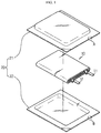
- FIG. 1 is an exploded perspective view illustrating the structure of the conventional pouch-type secondary battery schematically.
- the conventional pouch-type secondary battery includes an electrode assembly 10 and a pouch casing 20 as a fundamental structure.
- the electrode assembly 10 includes a positive electrode plate, a negative electrode plate and a separator interposed between the positive electrode plate and the negative electrode plate so that they may be insulated electrically from each other.
- the electrode assembly 10 is provided with a positive electrode tab extended from the positive electrode plate and a negative electrode tab extended from the negative electrode plate.
- the positive electrode tab and the negative electrode tab may be bound to a positive electrode lead 11 and a negative electrode lead 12, respectively, through resistance welding, ultrasonic welding, laser welding, or the like.
- Such electrode leads are exposed to the outside of the pouch casing to carry out a function of connecting the secondary battery with an external applicable instrument electrically, as electrodes of the secondary battery.
- the electrode assembly 10 is introduced to the pouch casing 20 together with an electrolyte.
- the pouch casing 20 may be divided into an upper pouch 21 and a lower pouch 22, and may also be referred to as a single cap or double cap depending on the location of a portion where the electrode assembly 10 is received.
- Such a pouch casing 20 may include aluminum foil inserted therein in order to protect an electrolyte introduced into the pouch casing and the electrode assembly 10, to supplement the electrochemical properties of a battery cell and to improve heat radiation property.
- the aluminum foil may have an insulation layer formed on the outside thereof, and the insulation layer may be coated with an insulation material, such as polyethylene terephthalate (PET) resin or nylon resin, to ensure insulation between the battery cell and the outside.
- PET polyethylene terephthalate
- the pouch casing 20 may be bonded or adhered at the outer circumferential portion thereof through hot fusion, or the like, during a sealing process.
- the bottom surface of the upper pouch 21 and the top surface of the lower pouch 22 may have an adhesive layer including casted polypropylene (PP) or polypropylene (PP) for the purpose of adhesion with each other.
- PP polypropylene
- PP polypropylene
- Such an adhesive layer functions to perform adhesion of the pouch casing 20 and serves as an insulation layer capable of preventing electric contact between the aluminum layer and the electrolyte introduced into the pouch casing 20.
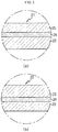
- FIG. 2 is an enlarged sectional view illustrating portion A and portion B of FIG. 1 .
- the upper pouch 21 has a predetermined layered structure having an insulation layer 25, an aluminum layer 24 and an adhesive layer 23 successively, and the lower pouch 22 includes an adhesive layer 23, an aluminum layer 24 and an insulation layer 25.
- heat and pressure may be applied to the bottom adhesive layer of the upper pouch 21 and the top adhesive layer 23 of the lower pouch 22.
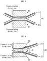
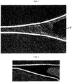
- FIG. 3 to FIG. 5 are schematic views illustrating a sealing portion pushed in a direction toward the inside of a cell, when a pouch casing is sealed according to the related art.
- the adhesive layer present at the sealing portion melts and flows due to the heat generated during sealing to form a temporary attachment region C, where the sealing portion is pushed in a direction toward the inside of the cell based on the parallel bonded end of the sealing portion.
- a temporary attachment region has a ball shape locally and the ball-shaped temporary attachment region is vulnerable to insulation and high-temperature durability.
- US 2006/0210872 A1 is concerned with a manufacturing method of a film-packaged electric device.
- KR 2012 0058960 A is concerned with a pouch type secondary battery manufacturing method.
- the present disclosure is designed to solve the problems of the related art, and therefore the present disclosure is directed to providing a method for sealing a pouch casing which can improve the durability of a sealing portion when sealing a pouch-type secondary battery.
- a method for sealing a pouch casing of a pouch-type secondary battery as defined in claim 1.
- the sealing step may be carried out so that the shape of a temporary attachment region, formed by the sealing portion pushed in a direction toward the inner space based on the parallel bonded end of the outer circumferential sealing portion of the upper pouch and the lower pouch, may not have a ball shape locally.
- the sealing step may be carried out by a heating block which performs hot fusion of the outer circumferential sealing portion of the upper pouch and the lower pouch through the transfer of a heat source.
- the sealing step may be carried out by applying external force to the upper pouch in the upward direction and to the lower pouch in the downward direction by using a vacuum adsorption pad.
- the second pressure in the sealing step may be a pneumatic pressure.
- the extent of the external force applied to the upper pouch in the upward direction is 2-5 times of the weight of the upper pouch
- the extent of the external force applied to the lower pouch in the downward direction is 2-5 times of the weight of the lower pouch.
- the external force application time is 1.5-2 times of the first pressure application time.
- the second pressure is 0.1-0.15 MPa.
- the second pressure application time is 1.5-2 times of the first pressure application time.
- the upper pouch and the lower pouch independently may include a metal layer, an insulation layer formed on one surface of the metal layer, and an adhesive layer formed on the other surface of the metal layer.
- the metal layer may be an aluminum layer.
- the insulation layer may include polyethylene terephthalate resin, nylon resin or a combination thereof.
- the adhesive layer may include casted polypropylene, polypropylene or a combination thereof.
- FIG. 6 is a schematic view illustrating the method for sealing a pouch casing according to an embodiment of the present disclosure.
- the method for sealing a pouch casing includes the steps of: (S10) a receiving step in which an electrode assembly is received in an inner space formed between an upper pouch and a lower pouch; and (S20) a sealing step in which a first pressure is applied to an outer circumferential sealing portion, where the upper pouch and the lower pouch are sealed, in the longitudinal direction, and then the pressure is relieved.
- a step of injecting an electrolyte and a step of aligning the sealing portion of the pouch casing 100 to seal the pouch casing 100 may be further carried out.
- sealing step S20 is carried out by applying external force to the upper pouch 110 in the upward direction D and to the lower pouch 120 in the downward direction D', or by applying a second pressure working in perpendicular to the first pressure to the sealing portion from the inner part of the pouch casing 100 in a direction E toward the outside.
- the pouch casing 100 When external force is applied to the upper pouch 110 in the upward direction D and to the lower pouch 120 in the downward direction D', or a second pressure working in perpendicular to the first pressure is applied to the sealing portion from the inner part of the pouch casing 100 in a direction E toward the outside, the pouch casing 100 is in close contact with a press jig 30 used for the sealing step to the highest degree.
- a press jig 30 used for the sealing step to the highest degree.
- the extent of the external force applied to the upper pouch in the upward direction and that of the external force applied to the lower pouch in the downward direction may vary with the size and weight of the upper pouch and those of the lower pouch, respectively.
- External force is applied in an extent corresponding to 2-5 times of the weight of each of the upper pouch and the lower pouch.
- an upper or lower pouch has a weight of about 10 gf.
- the extent of external force applied to each of the upper pouch and the lower pouch is preferably about 20-50 gf.
- the temporary attachment region may have a ball shape locally.
- sealing of the upper and lower pouches may be affected adversely and the adhesive layer melted upon sealing may be deformed.
- the external force application time is 1.5-2- times of the first pressure application time.
- the total external force application time is 1.5-2 times of the first pressure application time.
- the second pressure is 0.1-0.15 Mpa.
- the second pressure is less than 0.1 MPa, sufficient force cannot be applied to the temporary attachment region, thereby making it difficult to control the shape of the temporary attachment region.
- the second pressure exceeds 0.15 MPa, the adhesive layer of the pouch melted during sealing may be deformed undesirably.
- the second pressure application time is 1.5-2 times of the first pressure application time.
- the total second pressure application time is 1.5-2 times of the first pressure application time.
- the sealing step may be carried out by a heating block which performs hot fusion of the outer circumferential sealing portion of the upper pouch and the lower pouch through the transfer of a heat source.
- each of the upper pouch 110 and the lower pouch 120 includes a multilayer structure having a metal layer including an insulation layer, an adhesive layer, or the like.
- sealing step S20 is carried out by applying heat and pressure from a heating block to the outer circumferential adhesive layer of the upper pouch 110 and the lower pouch 120.
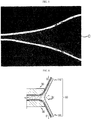
- FIG. 7 shows a sealing portion formed by the method for sealing a pouch according to an embodiment of the present disclosure. Referring to FIG. 7 , it can be seen that the temporary attachment region formed in the inner space of the secondary battery shows no ball shape locally.
- the upper pouch and the lower pouch may include a metal layer inserted therein in order to protect an electrolyte and an electrode assembly introduced into the pouch casing, to supplement the electrochemical properties of a battery cell and to improve heat dissipation property, or the like.
- Each of the upper pouch and the lower pouch may include a metal layer, an insulation layer formed on one surface of the metal layer and an adhesive layer formed on the other surface of the metal layer.
- the metal layer may be foil made of aluminum.
- the insulation layer coated with an insulation material such as polyethylene terephthalate (PET) resin or nylon resin, may be formed on one surface of the metal layer in order to ensure insulation between the battery cell and the outside.
- PET polyethylene terephthalate
- the adhesive layer such as casted polypropylene (CPP) or polypropylene (PP), may be formed on the other surface of the metal layer in order to attach the upper pouch and the lower pouch to each other.
- CPP casted polypropylene
- PP polypropylene
- Such an adhesive layer not only performs adhesion between the upper pouch and the lower pouch but also functions as an insulation layer which prevents electric contact between the metal layer and the electrolyte injected into the pouch casing.
- a sealing test was carried out for an upper pouch and lower pouch including a metal foil layer made of aluminum, a polyethylene terephthalate resin layer formed on one surface of the metal foil layer, and a polypropylene adhesive layer formed on the other surface of the metal foil layer, and having a weight of 10 gf.
- the adhesive layers were allowed to be in contact with each other.
- a test is carried out by applying a different extent of external force to each of the upper pouch and the lower pouch.
- the following Table 1 shows the test conditions, shape of a temporary attachment region and high-temperature sealing strength.
- the high-temperature sealing strength was determined by measuring sealing strength in a chamber at a high temperature of 80°C (measured at a rate of 50 mm/min).
- the test was carried out while controlling the external force application time might be 1.5 times of the first pressure application time. When the external force application time exceeds 2 times of the first pressure application time, the adhesive layer cannot be controlled sufficiently and sealing strength is degraded.
- Example 1 Example 2 Comparative Example 1 Comparative Example 2 Extent of external force 20 gf 50 gf 0 100 gf Shape of temporary attachment region Ball shape is not generated Ball shape is not generated Ball shape is generated Deformation High-temperature sealing strength 9.3 kgf/15mm 8.5 kgf/15mm 4.9 kgf/15mm 2.9 kgf/15mm
- Example 1 external force corresponding to 2 times of the weight of the pouch was applied to each of the upper pouch and the lower pouch in the upward direction and the downward direction, respectively.
- Example 2 external force corresponding to 5 times of the weight of the pouch was applied.
- the shape of temporary attachment region is not a ball shape but has an adequate degree of sealing strength.
- the shape of temporary attachment region is a ball shape locally and the high-temperature sealing strength is decreased to about a half of the high-temperature sealing strength of each example.
- Comparative Example 2 shows a high-temperature sealing strength of 2.9 kgf/15 mm, which is significantly lower than that of each Example.
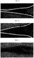
- FIG. 8 to FIG. 11 show the shape of each of the sealing portions according to Examples 1 and 2 and Comparative Examples 1 and 2. It can be seen that the drawings support the results of the above Table 1.
- Example 3 Comparative Example 3 Comparative Example 4 Extent of second pressure 0.1 MPa 0.15 MPa 0 0.2 MPa Shape of temporary attachment region Ball shape is reduced Ball shape is not generated Ball shape is generated Adhesive layer is damaged High-temperature sealing strength 7.3 kgf/15mm 9.0 kgf/15mm 4.9 kgf/15mm 4.3 kgf/15mm
- Example 3 although a minute ball shape is formed in the temporary attachment region, the ball shape is insignificant as compared to Comparative Examples. In the case of Example 4, no ball shape is generated and an adequate degree of sealing strength is provided.
- Comparative Example 4 shows a high-temperature sealing strength of 4.3 kgf/15 mm, which is significantly lower than that of each Example.
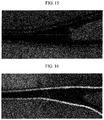
- FIG. 12 to FIG. 15 show the shape of each of the sealing portions according to Examples 3 and 4 and Comparative Examples 3 and 4. It can be seen that the drawings support the results of the above Table 2.
- Example 5 Extent of external force 20 gf Extent of second pressure 0.1 MPa Shape of temporary attachment region Ball shape is not generated High-temperature sealing strength 8.5 kgf/15mm
- FIG. 16 shows the sealing portion according to example 5.
Landscapes
- Chemical & Material Sciences (AREA)
- Chemical Kinetics & Catalysis (AREA)
- Electrochemistry (AREA)
- General Chemical & Material Sciences (AREA)
- Engineering & Computer Science (AREA)
- Manufacturing & Machinery (AREA)
- Inorganic Chemistry (AREA)
- Sealing Battery Cases Or Jackets (AREA)
Priority Applications (1)
| Application Number | Priority Date | Filing Date | Title |
|---|---|---|---|
| PL17856806T PL3373374T3 (pl) | 2016-09-28 | 2017-09-28 | Sposób uszczelniania obudowy pakietowej akumulatora |
Applications Claiming Priority (2)
| Application Number | Priority Date | Filing Date | Title |
|---|---|---|---|
| KR20160125013 | 2016-09-28 | ||
| PCT/KR2017/010880 WO2018062920A1 (ko) | 2016-09-28 | 2017-09-28 | 이차 전지의 파우치 케이스 실링 방법 |
Publications (3)
| Publication Number | Publication Date |
|---|---|
| EP3373374A1 EP3373374A1 (en) | 2018-09-12 |
| EP3373374A4 EP3373374A4 (en) | 2018-09-12 |
| EP3373374B1 true EP3373374B1 (en) | 2019-09-11 |
Family
ID=61759976
Family Applications (1)
| Application Number | Title | Priority Date | Filing Date |
|---|---|---|---|
| EP17856806.9A Active EP3373374B1 (en) | 2016-09-28 | 2017-09-28 | Method for sealing pouch case of secondary battery |
Country Status (6)
| Country | Link |
|---|---|
| US (1) | US10727453B2 (zh) |
| EP (1) | EP3373374B1 (zh) |
| KR (1) | KR102002614B1 (zh) |
| CN (1) | CN108370058B (zh) |
| PL (1) | PL3373374T3 (zh) |
| WO (1) | WO2018062920A1 (zh) |
Families Citing this family (5)
| Publication number | Priority date | Publication date | Assignee | Title |
|---|---|---|---|---|
| KR102555751B1 (ko) * | 2017-10-17 | 2023-07-14 | 주식회사 엘지에너지솔루션 | 가스 배출이 가능한 이차전지용 파우치형 케이스 |
| KR20200052070A (ko) * | 2018-11-06 | 2020-05-14 | 주식회사 아모그린텍 | 파우치형 배터리 카트리지 및 이를 포함하는 파우치형 배터리 팩 |
| CN111341946B (zh) * | 2018-12-18 | 2022-05-17 | 宁德新能源科技有限公司 | 电芯及电池 |
| EP3982436A4 (en) * | 2019-06-10 | 2022-07-27 | Nippon Steel Corporation | HOUSINGS FOR BATTERIES AND METHOD OF MANUFACTURE THEREOF |
| FR3110772B1 (fr) | 2020-05-20 | 2022-12-02 | Accumulateurs Fixes | Ensemble électrochimique, procédé et installation de fabrication correspondants |
Family Cites Families (22)
| Publication number | Priority date | Publication date | Assignee | Title |
|---|---|---|---|---|
| JP2004087239A (ja) * | 2002-08-26 | 2004-03-18 | Nissan Motor Co Ltd | 電池およびその製造方法、ならびに組電池、組電池モジュール |
| KR100544119B1 (ko) * | 2003-06-24 | 2006-01-23 | 삼성에스디아이 주식회사 | 파우치형 리튬 이차 전지 |
| CN1297019C (zh) * | 2003-12-20 | 2007-01-24 | 鸿富锦精密工业(深圳)有限公司 | 锂离子电池密封方法 |
| CN100361326C (zh) | 2004-03-23 | 2008-01-09 | 日本电气株式会社 | 薄膜覆盖电器件及其制造方法 |
| JP2006040747A (ja) | 2004-07-28 | 2006-02-09 | Nissan Motor Co Ltd | ラミネート電池の製造方法、ラミネート電池、およびヒートシーラ |
| KR100880386B1 (ko) * | 2005-06-03 | 2009-01-23 | 주식회사 엘지화학 | 신규한 구조의 이차전지 및 이를 포함하는 전지팩 |
| CN201508861U (zh) * | 2009-07-22 | 2010-06-16 | 比亚迪股份有限公司 | 一种电池盖帽组件及使用该组件的圆柱形锂离子电池 |
| DE102009028986A1 (de) * | 2009-08-28 | 2011-03-03 | SB LiMotive Company Ltd., Suwon | Verfahren und Einrichtung zum Aufbringen eines Druckes auf eine Batterie |
| KR101417152B1 (ko) * | 2009-10-09 | 2014-08-07 | 주식회사 엘지화학 | 파우치형 전지의 제조방법 및 파우치의 실링 장치 |
| CN101764200A (zh) * | 2010-01-20 | 2010-06-30 | 张力 | 一种电池电容包装壳体 |
| CN103098256B (zh) * | 2010-03-19 | 2016-01-20 | 株式会社Lg化学 | 袋式壳体和包括该袋式壳体的电池组 |
| US20110311862A1 (en) * | 2010-06-21 | 2011-12-22 | Samsung Sdi Co., Ltd. | Secondary battery |
| KR101203667B1 (ko) | 2010-11-30 | 2012-11-21 | 주식회사 엘지화학 | 최적 실링 효율의 파우치형 이차전지 제조방법, 파우치형 이차전지 및 이를 위한 히팅 지그 |
| KR101371040B1 (ko) | 2011-06-16 | 2014-03-10 | 에스케이이노베이션 주식회사 | 파우치형 이차전지 및 그 제조방법 |
| JP6111476B2 (ja) * | 2012-12-24 | 2017-04-12 | エルジー・ケム・リミテッド | 耐久性向上のためのシールマージンを有するパウチ型二次電池 |
| WO2014104841A1 (ko) * | 2012-12-28 | 2014-07-03 | 주식회사 엘지화학 | 이차 전지의 파우치 케이스 실링 장치 및 실링 방법 |
| KR101469188B1 (ko) * | 2013-04-23 | 2014-12-09 | (주)오렌지파워 | 경사 실링부를 포함하는 파우치형 이차전지 및 이의 제조 방법 |
| KR101838315B1 (ko) | 2013-10-18 | 2018-03-13 | 주식회사 엘지화학 | 파우치형 리튬 이차전지의 제조 방법 |
| US20150171431A1 (en) * | 2013-12-17 | 2015-06-18 | Samsung Electronics Co., Ltd. | Secondary battery and method of manufacturing the same |
| KR101772057B1 (ko) * | 2014-05-30 | 2017-08-28 | 주식회사 엘지화학 | 파우치 케이스 실링 장치 및 방법 |
| KR20160002176A (ko) * | 2014-06-30 | 2016-01-07 | 주식회사 엘지화학 | 이차전지 |
| CN105527049B (zh) * | 2016-03-03 | 2018-07-06 | 国轩新能源(苏州)有限公司 | 一种锂离子电池内压测试装置 |
-
2017
- 2017-09-28 US US15/776,248 patent/US10727453B2/en active Active
- 2017-09-28 PL PL17856806T patent/PL3373374T3/pl unknown
- 2017-09-28 EP EP17856806.9A patent/EP3373374B1/en active Active
- 2017-09-28 WO PCT/KR2017/010880 patent/WO2018062920A1/ko active Application Filing
- 2017-09-28 KR KR1020170126595A patent/KR102002614B1/ko active IP Right Grant
- 2017-09-28 CN CN201780004500.4A patent/CN108370058B/zh active Active
Non-Patent Citations (1)
| Title |
|---|
| None * |
Also Published As
| Publication number | Publication date |
|---|---|
| PL3373374T3 (pl) | 2019-12-31 |
| EP3373374A1 (en) | 2018-09-12 |
| CN108370058B (zh) | 2021-06-25 |
| KR20180035181A (ko) | 2018-04-05 |
| EP3373374A4 (en) | 2018-09-12 |
| WO2018062920A1 (ko) | 2018-04-05 |
| KR102002614B1 (ko) | 2019-07-22 |
| US10727453B2 (en) | 2020-07-28 |
| CN108370058A (zh) | 2018-08-03 |
| US20190207171A1 (en) | 2019-07-04 |
Similar Documents
| Publication | Publication Date | Title |
|---|---|---|
| EP3373374B1 (en) | Method for sealing pouch case of secondary battery | |
| US9755195B2 (en) | Apparatus and method for sealing pouch case of secondary battery | |
| JP4720065B2 (ja) | フィルム外装電池及び組電池 | |
| EP2434564B1 (en) | Rechargeable lithium battery in pouch form | |
| KR102347901B1 (ko) | 균열 방지 구조를 포함하는 파우치형 전지케이스 및 이의 제조방법 | |
| JP5418477B2 (ja) | 電池製造方法 | |
| CN111699566B (zh) | 电池用包装材料、其制造方法和电池 | |
| CN215955368U (zh) | 袋型电池壳体和袋型二次电池 | |
| KR101793412B1 (ko) | 이차전지용 양극탭의 제조방법 | |
| KR20120042537A (ko) | 전지 외장재 및 이를 포함하는 이차전지의 제조방법 | |
| US20230402686A1 (en) | Pouch Film for Secondary Battery and Manufacturing Method Thereof | |
| EP4037049A1 (en) | Secondary battery and sealing block | |
| KR101450951B1 (ko) | 안전성이 향상된 이차전지용 전극리드 및 이를 이용한 이차전지 | |
| US20230105613A1 (en) | Apparatus and Method for Folding Side | |
| KR102355197B1 (ko) | 리튬 이차 전지의 제조 방법 및 이에 의해 제조된 리튬 이차 전지 | |
| EP4345991A1 (en) | Battery cell and manufacturing method thereof | |
| WO2020246072A1 (ja) | 蓄電デバイス、蓄電デバイス集合体、電動自動車及び蓄電デバイスの製造方法 | |
| KR101236579B1 (ko) | 파우치형 리튬이차전지 | |
| KR20220060589A (ko) | 이차전지용 전극리드 필름 및 이를 구비한 이차전지용 전극리드 | |
| CN116723926A (zh) | 袋型电池及袋型电池的密封装置 | |
| KR20200052061A (ko) | 파우치 성형 장치 및 방법 | |
| KR20120059731A (ko) | 단자대 보강 구조를 갖는 파우치형 이차 전지 |
Legal Events
| Date | Code | Title | Description |
|---|---|---|---|
| STAA | Information on the status of an ep patent application or granted ep patent |
Free format text: STATUS: THE INTERNATIONAL PUBLICATION HAS BEEN MADE |
|
| PUAI | Public reference made under article 153(3) epc to a published international application that has entered the european phase |
Free format text: ORIGINAL CODE: 0009012 |
|
| STAA | Information on the status of an ep patent application or granted ep patent |
Free format text: STATUS: REQUEST FOR EXAMINATION WAS MADE |
|
| 17P | Request for examination filed |
Effective date: 20180605 |
|
| A4 | Supplementary search report drawn up and despatched |
Effective date: 20180806 |
|
| AK | Designated contracting states |
Kind code of ref document: A1 Designated state(s): AL AT BE BG CH CY CZ DE DK EE ES FI FR GB GR HR HU IE IS IT LI LT LU LV MC MK MT NL NO PL PT RO RS SE SI SK SM TR |
|
| AX | Request for extension of the european patent |
Extension state: BA ME |
|
| GRAP | Despatch of communication of intention to grant a patent |
Free format text: ORIGINAL CODE: EPIDOSNIGR1 |
|
| STAA | Information on the status of an ep patent application or granted ep patent |
Free format text: STATUS: GRANT OF PATENT IS INTENDED |
|
| RIC1 | Information provided on ipc code assigned before grant |
Ipc: H01M 2/02 20060101ALI20190612BHEP Ipc: H01M 10/04 20060101AFI20190612BHEP Ipc: H01M 10/0585 20100101ALN20190612BHEP |
|
| DAV | Request for validation of the european patent (deleted) | ||
| DAX | Request for extension of the european patent (deleted) | ||
| INTG | Intention to grant announced |
Effective date: 20190703 |
|
| GRAS | Grant fee paid |
Free format text: ORIGINAL CODE: EPIDOSNIGR3 |
|
| GRAA | (expected) grant |
Free format text: ORIGINAL CODE: 0009210 |
|
| STAA | Information on the status of an ep patent application or granted ep patent |
Free format text: STATUS: THE PATENT HAS BEEN GRANTED |
|
| AK | Designated contracting states |
Kind code of ref document: B1 Designated state(s): AL AT BE BG CH CY CZ DE DK EE ES FI FR GB GR HR HU IE IS IT LI LT LU LV MC MK MT NL NO PL PT RO RS SE SI SK SM TR |
|
| REG | Reference to a national code |
Ref country code: GB Ref legal event code: FG4D |
|
| REG | Reference to a national code |
Ref country code: CH Ref legal event code: EP |
|
| REG | Reference to a national code |
Ref country code: AT Ref legal event code: REF Ref document number: 1179676 Country of ref document: AT Kind code of ref document: T Effective date: 20190915 |
|
| REG | Reference to a national code |
Ref country code: DE Ref legal event code: R096 Ref document number: 602017007027 Country of ref document: DE Ref country code: IE Ref legal event code: FG4D |
|
| REG | Reference to a national code |
Ref country code: NL Ref legal event code: MP Effective date: 20190911 |
|
| REG | Reference to a national code |
Ref country code: LT Ref legal event code: MG4D |
|
| PG25 | Lapsed in a contracting state [announced via postgrant information from national office to epo] |
Ref country code: FI Free format text: LAPSE BECAUSE OF FAILURE TO SUBMIT A TRANSLATION OF THE DESCRIPTION OR TO PAY THE FEE WITHIN THE PRESCRIBED TIME-LIMIT Effective date: 20190911 Ref country code: HR Free format text: LAPSE BECAUSE OF FAILURE TO SUBMIT A TRANSLATION OF THE DESCRIPTION OR TO PAY THE FEE WITHIN THE PRESCRIBED TIME-LIMIT Effective date: 20190911 Ref country code: LT Free format text: LAPSE BECAUSE OF FAILURE TO SUBMIT A TRANSLATION OF THE DESCRIPTION OR TO PAY THE FEE WITHIN THE PRESCRIBED TIME-LIMIT Effective date: 20190911 Ref country code: BG Free format text: LAPSE BECAUSE OF FAILURE TO SUBMIT A TRANSLATION OF THE DESCRIPTION OR TO PAY THE FEE WITHIN THE PRESCRIBED TIME-LIMIT Effective date: 20191211 Ref country code: SE Free format text: LAPSE BECAUSE OF FAILURE TO SUBMIT A TRANSLATION OF THE DESCRIPTION OR TO PAY THE FEE WITHIN THE PRESCRIBED TIME-LIMIT Effective date: 20190911 Ref country code: NO Free format text: LAPSE BECAUSE OF FAILURE TO SUBMIT A TRANSLATION OF THE DESCRIPTION OR TO PAY THE FEE WITHIN THE PRESCRIBED TIME-LIMIT Effective date: 20191211 |
|
| PG25 | Lapsed in a contracting state [announced via postgrant information from national office to epo] |
Ref country code: ES Free format text: LAPSE BECAUSE OF FAILURE TO SUBMIT A TRANSLATION OF THE DESCRIPTION OR TO PAY THE FEE WITHIN THE PRESCRIBED TIME-LIMIT Effective date: 20190911 Ref country code: LV Free format text: LAPSE BECAUSE OF FAILURE TO SUBMIT A TRANSLATION OF THE DESCRIPTION OR TO PAY THE FEE WITHIN THE PRESCRIBED TIME-LIMIT Effective date: 20190911 Ref country code: GR Free format text: LAPSE BECAUSE OF FAILURE TO SUBMIT A TRANSLATION OF THE DESCRIPTION OR TO PAY THE FEE WITHIN THE PRESCRIBED TIME-LIMIT Effective date: 20191212 Ref country code: RS Free format text: LAPSE BECAUSE OF FAILURE TO SUBMIT A TRANSLATION OF THE DESCRIPTION OR TO PAY THE FEE WITHIN THE PRESCRIBED TIME-LIMIT Effective date: 20190911 Ref country code: AL Free format text: LAPSE BECAUSE OF FAILURE TO SUBMIT A TRANSLATION OF THE DESCRIPTION OR TO PAY THE FEE WITHIN THE PRESCRIBED TIME-LIMIT Effective date: 20190911 |
|
| REG | Reference to a national code |
Ref country code: AT Ref legal event code: MK05 Ref document number: 1179676 Country of ref document: AT Kind code of ref document: T Effective date: 20190911 |
|
| PG25 | Lapsed in a contracting state [announced via postgrant information from national office to epo] |
Ref country code: NL Free format text: LAPSE BECAUSE OF FAILURE TO SUBMIT A TRANSLATION OF THE DESCRIPTION OR TO PAY THE FEE WITHIN THE PRESCRIBED TIME-LIMIT Effective date: 20190911 Ref country code: AT Free format text: LAPSE BECAUSE OF FAILURE TO SUBMIT A TRANSLATION OF THE DESCRIPTION OR TO PAY THE FEE WITHIN THE PRESCRIBED TIME-LIMIT Effective date: 20190911 Ref country code: IT Free format text: LAPSE BECAUSE OF FAILURE TO SUBMIT A TRANSLATION OF THE DESCRIPTION OR TO PAY THE FEE WITHIN THE PRESCRIBED TIME-LIMIT Effective date: 20190911 Ref country code: RO Free format text: LAPSE BECAUSE OF FAILURE TO SUBMIT A TRANSLATION OF THE DESCRIPTION OR TO PAY THE FEE WITHIN THE PRESCRIBED TIME-LIMIT Effective date: 20190911 Ref country code: EE Free format text: LAPSE BECAUSE OF FAILURE TO SUBMIT A TRANSLATION OF THE DESCRIPTION OR TO PAY THE FEE WITHIN THE PRESCRIBED TIME-LIMIT Effective date: 20190911 Ref country code: PT Free format text: LAPSE BECAUSE OF FAILURE TO SUBMIT A TRANSLATION OF THE DESCRIPTION OR TO PAY THE FEE WITHIN THE PRESCRIBED TIME-LIMIT Effective date: 20200113 |
|
| PG25 | Lapsed in a contracting state [announced via postgrant information from national office to epo] |
Ref country code: SK Free format text: LAPSE BECAUSE OF FAILURE TO SUBMIT A TRANSLATION OF THE DESCRIPTION OR TO PAY THE FEE WITHIN THE PRESCRIBED TIME-LIMIT Effective date: 20190911 Ref country code: SM Free format text: LAPSE BECAUSE OF FAILURE TO SUBMIT A TRANSLATION OF THE DESCRIPTION OR TO PAY THE FEE WITHIN THE PRESCRIBED TIME-LIMIT Effective date: 20190911 Ref country code: IS Free format text: LAPSE BECAUSE OF FAILURE TO SUBMIT A TRANSLATION OF THE DESCRIPTION OR TO PAY THE FEE WITHIN THE PRESCRIBED TIME-LIMIT Effective date: 20200224 Ref country code: CZ Free format text: LAPSE BECAUSE OF FAILURE TO SUBMIT A TRANSLATION OF THE DESCRIPTION OR TO PAY THE FEE WITHIN THE PRESCRIBED TIME-LIMIT Effective date: 20190911 |
|
| REG | Reference to a national code |
Ref country code: DE Ref legal event code: R097 Ref document number: 602017007027 Country of ref document: DE |
|
| PLBE | No opposition filed within time limit |
Free format text: ORIGINAL CODE: 0009261 |
|
| STAA | Information on the status of an ep patent application or granted ep patent |
Free format text: STATUS: NO OPPOSITION FILED WITHIN TIME LIMIT |
|
| PG2D | Information on lapse in contracting state deleted |
Ref country code: IS |
|
| PG25 | Lapsed in a contracting state [announced via postgrant information from national office to epo] |
Ref country code: LU Free format text: LAPSE BECAUSE OF NON-PAYMENT OF DUE FEES Effective date: 20190928 Ref country code: DK Free format text: LAPSE BECAUSE OF FAILURE TO SUBMIT A TRANSLATION OF THE DESCRIPTION OR TO PAY THE FEE WITHIN THE PRESCRIBED TIME-LIMIT Effective date: 20190911 Ref country code: IE Free format text: LAPSE BECAUSE OF NON-PAYMENT OF DUE FEES Effective date: 20190928 Ref country code: IS Free format text: LAPSE BECAUSE OF FAILURE TO SUBMIT A TRANSLATION OF THE DESCRIPTION OR TO PAY THE FEE WITHIN THE PRESCRIBED TIME-LIMIT Effective date: 20200112 |
|
| REG | Reference to a national code |
Ref country code: BE Ref legal event code: MM Effective date: 20190930 |
|
| 26N | No opposition filed |
Effective date: 20200615 |
|
| PG25 | Lapsed in a contracting state [announced via postgrant information from national office to epo] |
Ref country code: MC Free format text: LAPSE BECAUSE OF FAILURE TO SUBMIT A TRANSLATION OF THE DESCRIPTION OR TO PAY THE FEE WITHIN THE PRESCRIBED TIME-LIMIT Effective date: 20190911 Ref country code: SI Free format text: LAPSE BECAUSE OF FAILURE TO SUBMIT A TRANSLATION OF THE DESCRIPTION OR TO PAY THE FEE WITHIN THE PRESCRIBED TIME-LIMIT Effective date: 20190911 Ref country code: BE Free format text: LAPSE BECAUSE OF NON-PAYMENT OF DUE FEES Effective date: 20190930 |
|
| REG | Reference to a national code |
Ref country code: CH Ref legal event code: PL |
|
| PG25 | Lapsed in a contracting state [announced via postgrant information from national office to epo] |
Ref country code: CY Free format text: LAPSE BECAUSE OF FAILURE TO SUBMIT A TRANSLATION OF THE DESCRIPTION OR TO PAY THE FEE WITHIN THE PRESCRIBED TIME-LIMIT Effective date: 20190911 |
|
| PG25 | Lapsed in a contracting state [announced via postgrant information from national office to epo] |
Ref country code: HU Free format text: LAPSE BECAUSE OF FAILURE TO SUBMIT A TRANSLATION OF THE DESCRIPTION OR TO PAY THE FEE WITHIN THE PRESCRIBED TIME-LIMIT; INVALID AB INITIO Effective date: 20170928 Ref country code: MT Free format text: LAPSE BECAUSE OF FAILURE TO SUBMIT A TRANSLATION OF THE DESCRIPTION OR TO PAY THE FEE WITHIN THE PRESCRIBED TIME-LIMIT Effective date: 20190911 |
|
| PG25 | Lapsed in a contracting state [announced via postgrant information from national office to epo] |
Ref country code: CH Free format text: LAPSE BECAUSE OF NON-PAYMENT OF DUE FEES Effective date: 20200930 Ref country code: LI Free format text: LAPSE BECAUSE OF NON-PAYMENT OF DUE FEES Effective date: 20200930 |
|
| PG25 | Lapsed in a contracting state [announced via postgrant information from national office to epo] |
Ref country code: TR Free format text: LAPSE BECAUSE OF FAILURE TO SUBMIT A TRANSLATION OF THE DESCRIPTION OR TO PAY THE FEE WITHIN THE PRESCRIBED TIME-LIMIT Effective date: 20190911 |
|
| PG25 | Lapsed in a contracting state [announced via postgrant information from national office to epo] |
Ref country code: MK Free format text: LAPSE BECAUSE OF FAILURE TO SUBMIT A TRANSLATION OF THE DESCRIPTION OR TO PAY THE FEE WITHIN THE PRESCRIBED TIME-LIMIT Effective date: 20190911 |
|
| P01 | Opt-out of the competence of the unified patent court (upc) registered |
Effective date: 20230408 |
|
| REG | Reference to a national code |
Ref country code: DE Ref legal event code: R081 Ref document number: 602017007027 Country of ref document: DE Owner name: LG ENERGY SOLUTION, LTD., KR Free format text: FORMER OWNER: LG CHEM. LTD., SEOUL, KR |
|
| REG | Reference to a national code |
Ref country code: GB Ref legal event code: 732E Free format text: REGISTERED BETWEEN 20230824 AND 20230831 |
|
| PGFP | Annual fee paid to national office [announced via postgrant information from national office to epo] |
Ref country code: GB Payment date: 20230821 Year of fee payment: 7 |
|
| PGFP | Annual fee paid to national office [announced via postgrant information from national office to epo] |
Ref country code: PL Payment date: 20230823 Year of fee payment: 7 Ref country code: FR Payment date: 20230821 Year of fee payment: 7 Ref country code: DE Payment date: 20230822 Year of fee payment: 7 |