EP3372756A1 - Zustandsdetektionsvorrichtung - Google Patents
Zustandsdetektionsvorrichtung Download PDFInfo
- Publication number
- EP3372756A1 EP3372756A1 EP18155321.5A EP18155321A EP3372756A1 EP 3372756 A1 EP3372756 A1 EP 3372756A1 EP 18155321 A EP18155321 A EP 18155321A EP 3372756 A1 EP3372756 A1 EP 3372756A1
- Authority
- EP
- European Patent Office
- Prior art keywords
- sensor unit
- detection device
- fastening means
- condition detection
- lock cylinder
- Prior art date
- Legal status (The legal status is an assumption and is not a legal conclusion. Google has not performed a legal analysis and makes no representation as to the accuracy of the status listed.)
- Granted
Links
Images

Classifications
-
- E—FIXED CONSTRUCTIONS
- E05—LOCKS; KEYS; WINDOW OR DOOR FITTINGS; SAFES
- E05B—LOCKS; ACCESSORIES THEREFOR; HANDCUFFS
- E05B9/00—Lock casings or latch-mechanism casings ; Fastening locks or fasteners or parts thereof to the wing
- E05B9/08—Fastening locks or fasteners or parts thereof, e.g. the casings of latch-bolt locks or cylinder locks to the wing
- E05B9/084—Fastening of lock cylinders, plugs or cores
-
- E—FIXED CONSTRUCTIONS
- E05—LOCKS; KEYS; WINDOW OR DOOR FITTINGS; SAFES
- E05B—LOCKS; ACCESSORIES THEREFOR; HANDCUFFS
- E05B45/00—Alarm locks
- E05B45/06—Electric alarm locks
- E05B2045/063—Electric alarm locks by movement of the wing
-
- E—FIXED CONSTRUCTIONS
- E05—LOCKS; KEYS; WINDOW OR DOOR FITTINGS; SAFES
- E05B—LOCKS; ACCESSORIES THEREFOR; HANDCUFFS
- E05B45/00—Alarm locks
- E05B45/06—Electric alarm locks
- E05B2045/065—Switch or sensor type used in alarm locks
- E05B2045/0655—Photo-diodes
-
- E—FIXED CONSTRUCTIONS
- E05—LOCKS; KEYS; WINDOW OR DOOR FITTINGS; SAFES
- E05B—LOCKS; ACCESSORIES THEREFOR; HANDCUFFS
- E05B47/00—Operating or controlling locks or other fastening devices by electric or magnetic means
- E05B2047/0048—Circuits, feeding, monitoring
- E05B2047/0067—Monitoring
- E05B2047/0068—Door closed
Definitions
- a state detection device for a door or the like having a door-locking device for locking a sash in a frame with mounting means for supporting the sash, comprising a sensor unit for detecting the closed state of the door.
- Such a state detection device is known from DE 10 2010 018 566 B4 known.
- the fastening means is used for screwing a locking device with a wing.
- a sensor unit for detecting a closed state of the door is arranged within the fastening means.
- a disadvantage of this condition detection device is that the fastening means is dependent on the lock dimensions of the locking device. Therefore, this design requires a very expensive storage of different units of the sensor unit with the fastening means. Furthermore, the fastening means with the sensor unit is exposed to strong influences from the environment, as e.g. a transmission path for data and energy between locking device and fastener is required.
- the invention is based on the problem, a state detection device of the type mentioned so on to form that it is particularly inexpensive to produce.
- the fastening means is at least partially designed to be permeable to signals of the sensor unit and that the sensor unit is arranged in front of the protruding into the closing device end of the fastening means in the closing device.
- the attachment means serves as a conductor for the signals of the sensor unit.
- the sensor unit itself is arranged in the closing device and thus reliably protected against environmental influences.
- the fasteners can be easily manufactured for the respective lock dimensions. Since the state detection device forms a unit with the locking device, the assembly is particularly simple. The condition detection device is thus particularly inexpensive to produce.
- the attachment means could comprise optical fibers suitable for the optical sensor or be made of a transparent plastic.
- the fastening means according to another advantageous embodiment of the invention has a particularly high stability, when the fastening means is tubular.
- an optical waveguide can be arranged in the tubular fastening element or a separating element for separating radiated and received light of the optical sensor unit.
- the detection of the closed, in the frame condition of the wing is particularly reliable according to another advantageous embodiment of the invention, when the sensor unit has a free end of the fastener facing, to be arranged in the frame reflector element and in the closing device in front of the other end of the fastener a Light emitting diode for emitting light and a photocell for receiving the reflected light from the reflector element.
- the sensor unit can reliably detect whether the wing is in the frame.
- the reflector element is mounted on a locking plate to be arranged in the frame.
- the reflector element has a defined polarization characteristic or reflection characteristic and the sensor unit has means for evaluating the characteristic of the reflections of the reflector element.
- a defined reflection characteristic is eg frequency-selective or influenced by the polarization direction.
- the reflector element can be formed with an intended orientation, a specific wavelength or a pattern of the reflections.
- the reflector element can also shift the range of the wavelength.
- the sensor unit may have a defined pulse operation.
- the specific wavelength may be in visible light or in the ultraviolet or infrared range.
- the adapted thereto sensor unit detects whether the light rays come from the reflector or the environment or a manipulation attempt, for example by introducing a polarizing filter. This will be In addition, the influence of light reflections from the environment kept low.
- the means for evaluating the characteristic of the reflections may be an evaluation electronics connected to the photocell.
- the state detection device especially in electronic or semi-electronic lock cylinders particularly reliable operation when the locking device has a lock cylinder, in particular a lock cylinder with an electronic locking mechanism and when the sensor unit is arranged in the lock cylinder.
- Another advantage of this design is that the condition detection device is automatically mounted with the lock cylinder. Further structural adjustments are not required.
- the transmitter for evaluating the signals of the photocell is preferably part of an electronic control of the lock cylinder.
- the sensor unit has means for determining the duration of the optical radiation. It is preferably a light-emitting diode is used, which emits laser radiation. There was an evaluation of the duration of the light or an evaluation of the phase position.
- a further embodiment according to the invention for detecting manipulation attempts provides that the sensor unit has means for determining the phase position of emitted and reflected radiation.
- a mechanical weakening of the lock cylinder in the region of the fastener can be largely avoided according to another advantageous embodiment of the invention, when the lock cylinder has a deflection unit for deflecting the signals of the sensor unit in the receptacle for the fastener.
- the deflection unit like the previously described reflector element, can have a defined polarization characteristic.
- the state detection device allows a particularly simple central monitoring of the wing lying in the frame when the locking device has a lock with a lock cylinder receptacle and when the sensor unit is arranged in the lock.
- This design is particularly advantageous for locking systems with multiple doors.
- a wide variety of length variants of the fastener can be according to another advantageous embodiment of the invention easily avoided if the fastener has two telescopically screwed together hollow screws.
- the fastening means with the two telescopically screwed hollow screws can be particularly easily solved by the locking device according to a further advantageous embodiment of the invention, when the fastening means with the two telescopically screwed together hollow screws has an inhibition of movement in the release direction.
- the fastener can be safely removed at any time as a whole unit of the locking device and out of the frame, or the wing.
- FIG. 1 shows a door with a lockable in a frame 1 wings 2 and with a locking device 3.
- the locking device 3 has a lock 4 with a lock cylinder 5.
- a state detection device 6 is also arranged.
- FIG. 2 schematically shows a portion of the locking device 3 with adjacent areas of the door FIG. 1
- a fastening means 7 for connecting the lock cylinder 5 in the wing 2 has a hollow screw 8.
- a reflector element 9 is arranged opposite the free end of the fastening means 7.
- the lock cylinder 5 has a receptacle 10 with an internal thread for the other end of the fastener 7.
- an optical sensor unit 11 is arranged.
- the optical sensor unit 11 has a photocell 12 and a light emitting diode 13.
- an optical waveguide 14 for guiding the light between the light emitting diode 13, the reflector element 9 and the photocell 12 is arranged.
- the fastening means 7 may also be transparent, designed as an optical waveguide 14.
- the light emitted from the light emitting diode 13 is radiated by the fixing means 7.
- the wing 2 In the closed state of the door, the wing 2 is in the frame 1, so that the reflector element 9, as shown, is located in front of the free end of the fastening means 7.
- the reflector element 9 reflects the light of the light emitting diode 13 to the photocell 12.
- the photocell 12 thus generates a signal when the door is closed.
- the light emitting diode 13 and the photocell 12 are arranged in the embodiment in the lock cylinder 5. In an alternative, not shown embodiment, the light emitting diode 13 and the photocell 12 may be arranged in the lock 4 near the lock cylinder 5.
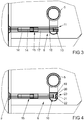
- FIG. 3 shows a further embodiment of the state detection device 6, which differs from the FIG. 2 characterized in that a fastening means 15 has two telescopically interconnected hollow screws 16, 17.
- the in FIG. 2 described in the receptacle 10 of the lock cylinder 5 screwed hollow screw 17 has a stop 18 on the lock cylinder 5. Otherwise, the condition detection device 6 with the optical sensor unit 11 as the off FIG. 2 built up.
- FIG. 4 shows a further embodiment of the state detection device 6, which differs from the FIG. 3 differs in that in the receptacle 10 of the lock cylinder 5 for the fastening means 15, a deflection unit 19 for deflecting the light with a prism 20 or a reflector is arranged.
- a photocell 21 and a light emitting diode 22 of an optical sensor unit 23 are arranged next to the receptacle 10 for the fastening means 15 in the lock cylinder 5.
- the deflection unit 19 transmits the signals between the light-emitting diode 22, the reflector element 9 and the photocell 21. Otherwise, the state detection device 6 is like that FIG. 3 built up.
Landscapes
- Engineering & Computer Science (AREA)
- Mechanical Engineering (AREA)
- Geophysics And Detection Of Objects (AREA)
- Power-Operated Mechanisms For Wings (AREA)
- Lock And Its Accessories (AREA)
Abstract
Description
- Zustandsdetektionsvorrichtung für eine eine Schließeinrichtung zur Verriegelung eines Flügels in einem Rahmen aufweisende Tür oder dergleichen mit einem zur auf dem Rahmen gerichteten Montage vorgesehenen Befestigungsmittel zur Halterung der Schließeinrichtung, mit einer Sensoreinheit zur Erfassung des geschlossenen Zustands der Tür.
- Eine solche Zustandsdetektionsvorrichtung ist aus der
DE 10 2010 018 566 B4 bekannt. Bei dieser Zustandsdetektionsvorrichtung dient das Befestigungsmittel zur Verschraubung einer Schließeinrichtung mit einem Flügel. Innerhalb des Befestigungsmittels ist eine Sensoreinheit zur Erfassung eines geschlossenen Zustandes der Tür angeordnet. - Nachteilig bei dieser Zustandsdetektionsvorrichtung ist jedoch, dass das Befestigungsmittel abhängig ist von den Schlossmaßen der Schließeinrichtung. Daher erfordert diese Gestaltung eine sehr aufwändige Bevorratung von unterschiedlichen Einheiten der Sensoreinheit mit dem Befestigungsmittel. Weiterhin ist das Befestigungsmittel mit der Sensoreinheit starken Einflüssen aus der Umgebung ausgesetzt, da z.B. eine Übertragungsstrecke für Daten und Energie zwischen Schließeinrichtung und Befestigungsmittel erforderlich wird.
- Der Erfindung liegt das Problem zugrunde, eine Zustandsdetektionsvorrichtung der eingangs genannten Art so weiter zu bilden, dass sie besonders kostengünstig herstellbar ist.
- Dieses Problem wird erfindungsgemäß dadurch gelöst, dass das Befestigungsmittel zumindest teilweise für Signale der Sensoreinheit durchlässig gestaltet ist und dass die Sensoreinheit vor dem in die Schließeinrichtung hineinragenden Ende des Befestigungsmittels in der Schließeinrichtung angeordnet ist.
- Durch diese Gestaltung dient das Befestigungsmittel als Leiter für die Signale der Sensoreinheit. Die Sensoreinheit selbst ist in der Schließeinrichtung angeordnet und damit zuverlässig geschützt vor Umgebungseinflüssen. Die Befestigungsmittel lassen sich einfach für die jeweiligen Schlossmaße fertigen. Da die Zustandsdetektionsvorrichtung mit der Schließeinrichtung eine Einheit bildet, gestaltet sich die Montage besonders einfach. Die Zustandsdetektionsvorrichtung ist damit besonders kostengünstig herstellbar.
- Ein berührungsloses Abtasten des im Rahmen liegenden Flügels gestaltet sich gemäß einer anderen vorteilhaften Weiterbildung der Erfindung konstruktiv besonders einfach, wenn die Sensoreinheit als optische Sensoreinheit, beispielsweise mit einer Leuchtdiode, ausgebildet ist.
- Das Befestigungsmittel könnte für den optischen Sensor geeignete Lichtwellenleiter aufweisen oder aus einem transparenten Kunststoff gefertigt sein. Das Befestigungsmittel weist jedoch gemäß einer anderen vorteilhaften Weiterbildung der Erfindung eine besonders hohe Stabilität auf, wenn das Befestigungsmittel rohrförmig gestaltet ist. Zur Führung des Lichts kann in dem rohrförmigen Befestigungselement ein Lichtwellenleiter angeordnet sein oder ein Trennelement zur Trennung von abgestrahlten und empfangenen Licht der optischen Sensoreinheit.
- Die Erfassung des geschlossenen, im Rahmen liegenden Zustandes des Flügels gestaltet sich gemäß einer anderen vorteilhaften Weiterbildung der Erfindung besonders zuverlässig, wenn die Sensoreinheit ein dem freien Ende des Befestigungsmittels gegenüberstehendes, im Rahmen anzuordnendes Reflektorelement hat und in der Schließeinrichtung vor dem anderem Ende des Befestigungsmittels eine Leuchtdiode zur Abstrahlung von Licht und eine Fotozelle zum Empfang des von dem Reflektorelement reflektierten Lichts hat. Durch diese Gestaltung vermag die Sensoreinheit zuverlässig zu detektieren, ob der Flügel im Rahmen liegt. Vorzugsweise ist das Reflektorelement auf einem im Rahmen anzuordnenden Schließblech befestigt.
- Manipulationsversuche lassen sich gemäß einer anderen vorteilhaften Weiterbildung der Erfindung weitgehend vermeiden, wenn das Reflektorelement eine definierte Polarisationscharakteristik oder Reflexionscharakteristik hat und die Sensoreinheit Mittel zur Auswertung der Charakteristik der Reflexionen des Reflektorelements hat. Eine definierte Reflexionscharakteristik ist z.B. frequenzselektiv oder durch die Polarisationsrichtung beeinflusst. Durch diese Gestaltung lässt sich das Reflektorelement mit einer vorgesehenen Orientierung, einer spezifischen Wellenlänge oder einem Muster der Reflektionen ausbilden. Alternativ kann das Reflektorelement auch den Bereich der Wellenlänge verschieben. Ebenso kann die Sensoreinheit einen definierten Pulsbetrieb aufweisen. Die spezifische Wellenlänge kann im sichtbaren Licht oder im Ultraviolett oder Infrarotbereich liegen. Die hierzu angepasste Sensoreinheit erfasst, ob die Lichtstrahlen von dem Reflektor kommen oder der Umgebung oder einem Manipulationsversuch, z.B. durch Einbringen eines Polarisationsfilters. Damit wird zudem der Einfluss von Lichtreflexen aus der Umgebung gering gehalten. Die Mittel zur Auswertung der Charakteristik der Reflexionen können eine mit der Fotozelle verbundene Auswerteelektronik sein.
- Die Zustandsdetektionsvorrichtung ermöglicht gemäß einer anderen vorteilhaften Weiterbildung der Erfindung insbesondere bei elektronischen oder teilelektronischen Schließzylindern einen besonders zuverlässigen Betrieb, wenn die Schließeinrichtung einen Schließzylinder, insbesondere einen Schließzylinder mit einem elektronischen Sperrmechanismus hat und wenn die Sensoreinheit in dem Schließzylinder angeordnet ist. Ein weiterer Vorteil dieser Gestaltung besteht darin, dass die Zustandsdetektionsvorrichtung automatisch mit dem Schließzylinder montiert ist. Weitere bauliche Anpassungen sind nicht erforderlich. Die Auswerteelektronik zur Auswertung der Signale der Fotozelle ist vorzugsweise Teil einer Steuerelektronik des Schließzylinders.
- Durch eine weitere Ausgestaltung werden Manipulationsversuche besonders gut erkannt, wenn die Sensoreinheit Mittel zur Bestimmung der Laufzeit der optischen Strahlung hat. Es kommt vorzugsweise eine lichtaussendende Diode zum Einsatz, die Laserstrahlung aussendet. Es erfolgte eine Auswertung der Laufzeit des Lichts oder eine Auswertung der Phasenlage.
- Eine weitere erfindungsgemäße Ausgestaltung zur Erkennung von Manipulationsversuchen sieht vor, dass die Sensoreinheit Mittel zur Bestimmung der Phasenlage von emittierter und reflektierter Strahlung hat.
- Eine mechanische Schwächung des Schließzylinders im Bereich des Befestigungsmittels lässt sich gemäß einer anderen vorteilhaften Weiterbildung der Erfindung weitgehend vermeiden, wenn der Schließzylinder in der Aufnahme für das Befestigungsmittel eine Umlenkeinheit zur Umlenkung der Signale der Sensoreinheit hat. Die Umlenkeinheit kann wie das zuvor beschriebene Reflektorelement eine definierte Polarisationscharakteristik aufweisen.
- Die Zustandsdetektionsvorrichtung ermöglicht gemäß einer anderen vorteilhaften Weiterbildung der Erfindung eine besonders einfache zentrale Überwachung des im Rahmen liegenden Flügels, wenn die Schließeinrichtung ein Schloss mit einer Schließzylinderaufnahme aufweist und wenn die Sensoreinheit in dem Schloss angeordnet ist. Diese Gestaltung ist insbesondere bei Schließanlagen mit mehreren Türen von Vorteil.
- Eine große Vielfalt von Längenvarianten des Befestigungsmittels lässt sich gemäß einer anderen vorteilhaften Weiterbildung der Erfindung einfach vermeiden, wenn das Befestigungsmittel zwei teleskopartig miteinander verschraubte Hohlschrauben aufweist.
- Das Befestigungsmittel mit den zwei teleskopartig miteinander verschraubten Hohlschrauben lässt sich gemäß einer weiteren vorteilhaften Weiterbildung der Erfindung besonders einfach von der Schließeinrichtung lösen, wenn das Befestigungsmittel mit den zwei teleskopartig miteinander verschraubten Hohlschrauben eine Hemmung der Bewegung in Löserichtung aufweist. Das Befestigungsmittel lässt sich dadurch jederzeit sicher als gesamte Einheit von der Schließeinrichtung entfernen und aus dem Rahmen, bzw. dem Flügel führen.
- Die Erfindung lässt zahlreiche Ausführungsformen zu. Zur weiteren Verdeutlichung ihres Grundprinzips sind mehrere davon in der Zeichnung dargestellt und werden nachfolgend beschrieben. Diese zeigt in
- Fig. 1
- eine Tür mit einer Schließeinrichtung und einer Zustandsdetektionsvorrichtung,
- Fig. 2
- einen Teilbereich der Tür mit einer ersten Ausführungsform der Zustandsdetektionsvorrichtung,
- Fig. 3
- einen Teilbereich der Tür mit einer weiteren Ausführungsform der Zustandsdetektionsvorrichtung,
- Fig. 4
- einen Teilbereich der Tür mit einer weiteren Ausführungsform der Zustandsdetektionsvorrichtung.
-
Figur 1 zeigt eine Tür mit einem in einem Rahmen 1 verriegelbaren Flügel 2 und mit einer Schließeinrichtung 3. Die Schließeinrichtung 3 hat ein Schloss 4 mit einem Schließzylinder 5. In der Schließeinrichtung 3 ist zudem eine Zustandsdetektionsvorrichtung 6 angeordnet. -
Figur 2 zeigt schematisch einen Teilbereich der Schließeinrichtung 3 mit angrenzenden Bereichen der Tür ausFigur 1 . Ein Befestigungsmittel 7 zur Verbindung des Schließzylinders 5 in dem Flügel 2 hat eine Hohlschraube 8. Auf dem Rahmen 1 ist ein Reflektorelement 9 dem freien Ende des Befestigungsmittels 7 gegenüberstehend angeordnet. Der Schließzylinder 5 hat eine Aufnahme 10 mit einem Innengewinde für das andere Ende des Befestigungsmittels 7. Diesem Ende des Befestigungsmittels 7 gegenüberstehend ist eine optische Sensoreinheit 11 angeordnet. Die optische Sensoreinheit 11 hat eine Fotozelle 12 und eine Leuchtdiode 13. In dem Befestigungsmittel 7 ist ein Lichtwellenleiter 14 zur Leitung des Lichts zwischen der Leuchtdiode 13, dem Reflektorelement 9 und der Fotozelle 12 angeordnet. In einer alternativen Ausführungsform kann das Befestigungsmittel 7 auch transparent, als Lichtwellenleiter 14 ausgebildet sein. - Das von der Leuchtdiode 13 abgestrahlte Licht wird durch das Befestigungsmittel 7 gestrahlt. Im geschlossenen Zustand der Tür liegt der Flügel 2 in dem Rahmen 1, so dass das Reflektorelement 9, wie dargestellt, vor dem freien Ende des Befestigungsmittels 7 liegt. In diesem Fall reflektiert das Reflektorelement 9 das Licht der Leuchtdiode 13 zu der Fotozelle 12. Die Fotozelle 12 erzeugt damit ein Signal, wenn die Tür geschlossen ist. Die Leuchtdiode 13 und die Fotozelle 12 sind in dem Ausführungsbeispiel in dem Schließzylinder 5 angeordnet. In einer alternativen, nicht dargestellten Ausführungsform können die Leuchtdiode 13 und die Fotozelle 12 auch in dem Schloss 4 nahe dem Schließzylinder 5 angeordnet sein.
-
Figur 3 zeigt eine weitere Ausführungsform der Zustandsdetektionsvorrichtung 6, welche sich von der ausFigur 2 dadurch unterscheidet, dass ein Befestigungsmittel 15 zwei teleskopartig miteinander verbundene Hohlschrauben 16, 17 hat. Der inFigur 2 beschriebene Lichtwellenleiter 14 durchdringt die beiden Hohlschrauben 16, 17. Die in die Aufnahme 10 des Schließzylinders 5 eingedrehte Hohlschraube 17 hat einen Anschlag 18 am Schließzylinder 5. Ansonsten ist die Zustandsdetektionsvorrichtung 6 mit der optischen Sensoreinheit 11 wie die ausFigur 2 aufgebaut. -
Figur 4 zeigt eine weitere Ausführungsform der Zustandsdetektionsvorrichtung 6, welche sich von der ausFigur 3 dadurch unterscheidet, dass in der Aufnahme 10 des Schließzylinders 5 für das Befestigungsmittel 15 eine Umlenkeinheit 19 zur Umlenkung des Lichts mit einem Prisma 20 oder einem Reflektor angeordnet ist. Eine Fotozelle 21 und eine Leuchtdiode 22 einer optischen Sensoreinheit 23 sind neben der Aufnahme 10 für das Befestigungsmittel 15 in dem Schließzylinder 5 angeordnet. Die Umlenkeinheit 19 überträgt die Signale zwischen Leuchtdiode 22, Reflektorelement 9 und Fotozelle 21. Ansonsten ist die Zustandsdetektionsvorrichtung 6 wie die ausFigur 3 aufgebaut.
Claims (12)
- Zustandsdetektionsvorrichtung (6) für eine eine Schließeinrichtung (3) zur Verriegelung eines Flügels (2) in einem Rahmen (1) aufweisende Tür oder dergleichen mit einem zur auf dem Rahmen (1) gerichteten Montage vorgesehenen Befestigungsmittel (7, 15) zur Halterung der Schließeinrichtung (3), mit einer Sensoreinheit (11, 23) zur Erfassung des geschlossenen Zustands der Tür, dadurch gekennzeichnet, dass das Befestigungsmittel (7, 15) zumindest teilweise für Signale der Sensoreinheit (11, 23) durchlässig gestaltet ist und dass die Sensoreinheit (11, 23) vor dem in die Schließeinrichtung (3) hineinragenden Ende des Befestigungsmittels (7, 15) in der Schließeinrichtung (3) angeordnet ist.
- Zustandsdetektionsvorrichtung nach Anspruch 1, dadurch gekennzeichnet, dass die Sensoreinheit (11, 23) als optischen Sensoreinheit ausgebildet ist.
- Zustandsdetektionsvorrichtung nach Anspruch 1 oder 2, dadurch gekennzeichnet, dass das Befestigungsmittel (7, 15) rohrförmig gestaltet ist.
- Zustandsdetektionsvorrichtung nach einem der Ansprüche 1 bis 3, dadurch gekennzeichnet, dass die Sensoreinheit (11, 23) ein dem freien Ende des Befestigungsmittels (7, 15) gegenüberstehend im Rahmen (1) anzuordnendes Reflektorelement (9) hat und in der Schließeinrichtung (3) vor dem anderen Ende des Befestigungsmittels (7, 15) eine Leuchtdiode (13, 22) zur Abstrahlung von Licht und eine Fotozelle (12, 21) zum Empfang des von dem Reflektorelement (9) reflektierten Lichts hat.
- Zustandsdetektionsvorrichtung nach Anspruch 4, dadurch gekennzeichnet, dass das Reflektorelement (9) eine definierte Polarisationscharakteristik oder Reflexionscharakteristik hat und die Sensoreinheit (11, 23) Mittel zur Auswertung der Charakteristik der Reflexionen des Reflektorelements (9) hat.
- Zustandsdetektionsvorrichtung nach Anspruch 5, dadurch gekennzeichnet, dass die Sensoreinheit (11, 23) Mittel zur Bestimmung der Laufzeit der optischen Strahlung hat.
- Zustandsdetektionsvorrichtung nach Anspruch 5, dadurch gekennzeichnet, dass die Sensoreinheit (11, 23) Mittel zur Bestimmung der Phasenlage von emittierter und reflektierter Strahlung hat.
- Zustandsdetektionsvorrichtung nach einem der Ansprüche 1 bis 7, dadurch gekennzeichnet, dass die Schließeinrichtung (3) einen Schließzylinder (5), insbesondere einen Schließzylinder (5) mit einem elektronischen Sperrmechanismus hat und dass die Sensoreinheit (11, 23) in dem Schließzylinder (5) angeordnet ist.
- Zustandsdetektionsvorrichtung nach Anspruch 8, dadurch gekennzeichnet, dass der Schließzylinder (5) in der Aufnahme (10) für das Befestigungsmittel (15) eine Umlenkeinheit (19) zur Umlenkung der Signale der Sensoreinheit (23) hat.
- Zustandsdetektionsvorrichtung nach einem der Ansprüche 1 bis 7, dadurch gekennzeichnet, dass die Schließeinrichtung (3) ein Schloss (4) mit einer Schließzylinderaufnahme aufweist und dass die Sensoreinheit in dem Schloss (4) angeordnet ist.
- Zustandsdetektionsvorrichtung nach einem der Ansprüche 1 bis 10, dadurch gekennzeichnet, dass das Befestigungsmittel (15) zwei teleskopartig miteinander verschraubte Hohlschrauben (16, 17) aufweist.
- Zustandsdetektionsvorrichtung nach Anspruch 11, dadurch gekennzeichnet, dass das Befestigungsmittel (15) mit den zwei teleskopartig miteinander verschraubten Hohlschrauben (16, 17) eine Hemmung der Bewegung in Löserichtung aufweist.
Applications Claiming Priority (1)
| Application Number | Priority Date | Filing Date | Title |
|---|---|---|---|
| DE102017202633.2A DE102017202633A1 (de) | 2017-02-20 | 2017-02-20 | Zustandsdetektionsvorrichtung |
Publications (2)
| Publication Number | Publication Date |
|---|---|
| EP3372756A1 true EP3372756A1 (de) | 2018-09-12 |
| EP3372756B1 EP3372756B1 (de) | 2019-08-28 |
Family
ID=61167982
Family Applications (1)
| Application Number | Title | Priority Date | Filing Date |
|---|---|---|---|
| EP18155321.5A Active EP3372756B1 (de) | 2017-02-20 | 2018-02-06 | Zustandsdetektionsvorrichtung |
Country Status (2)
| Country | Link |
|---|---|
| EP (1) | EP3372756B1 (de) |
| DE (1) | DE102017202633A1 (de) |
Cited By (1)
| Publication number | Priority date | Publication date | Assignee | Title |
|---|---|---|---|---|
| DE202021103247U1 (de) | 2021-06-16 | 2021-06-30 | Aug. Winkhaus Gmbh & Co. Kg | Schließeinrichtung für einen gegen einen Rahmen schwenkbaren Flügel |
Citations (4)
| Publication number | Priority date | Publication date | Assignee | Title |
|---|---|---|---|---|
| US20080012705A1 (en) * | 2006-07-14 | 2008-01-17 | Osi Security Devices | Door position monitor |
| DE102010018566A1 (de) * | 2010-04-28 | 2011-11-03 | Simonsvoss Technologies Ag | Zustandsdetektionsvorrichtung für eine Schließvorrichtung und eine solche umfassende Schließvorrichtung |
| DE102012025474A1 (de) * | 2012-12-29 | 2014-07-03 | Klaus Meister | Tür- und Riegelzustandsdetektionsvorrichtung |
| DE102016006151A1 (de) * | 2015-05-19 | 2016-11-24 | Simonsvoss Technologies Gmbh | Zustandsdetektionsvorrichtung für eine Schließvorrichtung |
Family Cites Families (3)
| Publication number | Priority date | Publication date | Assignee | Title |
|---|---|---|---|---|
| US6411215B1 (en) | 1999-02-19 | 2002-06-25 | J. Mitchell Shnier | Optical methods for detecting the position or state of an object |
| WO2012092492A2 (en) | 2010-12-29 | 2012-07-05 | Secureall Corporation | Alignment-related operation and position sensing of electronic and other locks and other objects |
| US8690205B2 (en) | 2011-02-21 | 2014-04-08 | Yale Security Inc. | Door lockset |
-
2017
- 2017-02-20 DE DE102017202633.2A patent/DE102017202633A1/de not_active Withdrawn
-
2018
- 2018-02-06 EP EP18155321.5A patent/EP3372756B1/de active Active
Patent Citations (4)
| Publication number | Priority date | Publication date | Assignee | Title |
|---|---|---|---|---|
| US20080012705A1 (en) * | 2006-07-14 | 2008-01-17 | Osi Security Devices | Door position monitor |
| DE102010018566A1 (de) * | 2010-04-28 | 2011-11-03 | Simonsvoss Technologies Ag | Zustandsdetektionsvorrichtung für eine Schließvorrichtung und eine solche umfassende Schließvorrichtung |
| DE102012025474A1 (de) * | 2012-12-29 | 2014-07-03 | Klaus Meister | Tür- und Riegelzustandsdetektionsvorrichtung |
| DE102016006151A1 (de) * | 2015-05-19 | 2016-11-24 | Simonsvoss Technologies Gmbh | Zustandsdetektionsvorrichtung für eine Schließvorrichtung |
Cited By (1)
| Publication number | Priority date | Publication date | Assignee | Title |
|---|---|---|---|---|
| DE202021103247U1 (de) | 2021-06-16 | 2021-06-30 | Aug. Winkhaus Gmbh & Co. Kg | Schließeinrichtung für einen gegen einen Rahmen schwenkbaren Flügel |
Also Published As
| Publication number | Publication date |
|---|---|
| EP3372756B1 (de) | 2019-08-28 |
| DE102017202633A1 (de) | 2018-08-23 |
Similar Documents
| Publication | Publication Date | Title |
|---|---|---|
| DE3780693T2 (de) | Sicherheitszaun. | |
| DE4444839C1 (de) | Vorrichtung zur Überwachung des Fenster-Verschlußzustands eines Öffnungs-Abdeckelements | |
| WO2020064769A1 (de) | Betätigungshandhabe mit zutrittskontrollsystem | |
| DE19801632C2 (de) | Reflexlichtschranke, insbesondere zur Erkennung transparenter, polarisierender Materialien, sowie ein Verfahren zur Verbesserung der Störsicherheit von Reflexlichtschranken | |
| DE102011008654A1 (de) | Beschlagsintegrierte Überwachungseinrichtung | |
| EP3372756B1 (de) | Zustandsdetektionsvorrichtung | |
| EP2023164A2 (de) | Optischer Sensor | |
| EP2053428B1 (de) | Optoelektronischer Sensor | |
| DE102017121891A1 (de) | Optoelektronischer Sensor und Verfahren zur Erfassung von transparenten Objekten | |
| DE102010042142A1 (de) | Messgerät zur Erfassung der Drehbewegung einer Welle | |
| EP3736783B1 (de) | Geldautomat | |
| EP2110500B1 (de) | Überwachungseinrichtung eines Treibstangenbeschlages eines Fensters | |
| DE19806124C1 (de) | Sensor | |
| WO2020064774A1 (de) | Zutrittsystem | |
| EP2535743B1 (de) | Optischer sensor | |
| DE102015220139A1 (de) | Überwachungseinrichtung eines Treibstangenbeschlages für einen in einem Rahmen verriegelbaren Flügel | |
| EP3454312B1 (de) | Optischer rauchmelder mit einem aufschwenkbaren leiterplattenabschnitt mit einem darauf angeordneten lichtsender und/oder lichtempfänger | |
| DE202008016946U1 (de) | Lichtgitter oder Lichtschranke | |
| DE3535301A1 (de) | Schliessstueck bzw. -kasten | |
| DE202021100807U1 (de) | Fensteralarmsystem | |
| DE102007051133B4 (de) | Drehtüranlage mit einer Sensorvorrichtung für die Überwachung von vertikalen Türkanten | |
| DE102005046554A1 (de) | Reflexionslichtschranke | |
| EP4700198A1 (de) | Türanordnung, insbesondere haus- oder balkontüranordnung | |
| DE202014001263U1 (de) | Vorrichtung zum Bestimmen eines Öffnungswinkels eines Türblatts und optischer Sensor | |
| EP4089257B1 (de) | Überwachungseinrichtung für einen treibstangenbeschlag |
Legal Events
| Date | Code | Title | Description |
|---|---|---|---|
| PUAI | Public reference made under article 153(3) epc to a published international application that has entered the european phase |
Free format text: ORIGINAL CODE: 0009012 |
|
| STAA | Information on the status of an ep patent application or granted ep patent |
Free format text: STATUS: THE APPLICATION HAS BEEN PUBLISHED |
|
| AK | Designated contracting states |
Kind code of ref document: A1 Designated state(s): AL AT BE BG CH CY CZ DE DK EE ES FI FR GB GR HR HU IE IS IT LI LT LU LV MC MK MT NL NO PL PT RO RS SE SI SK SM TR |
|
| AX | Request for extension of the european patent |
Extension state: BA ME |
|
| STAA | Information on the status of an ep patent application or granted ep patent |
Free format text: STATUS: REQUEST FOR EXAMINATION WAS MADE |
|
| 17P | Request for examination filed |
Effective date: 20190214 |
|
| RBV | Designated contracting states (corrected) |
Designated state(s): AL AT BE BG CH CY CZ DE DK EE ES FI FR GB GR HR HU IE IS IT LI LT LU LV MC MK MT NL NO PL PT RO RS SE SI SK SM TR |
|
| GRAP | Despatch of communication of intention to grant a patent |
Free format text: ORIGINAL CODE: EPIDOSNIGR1 |
|
| STAA | Information on the status of an ep patent application or granted ep patent |
Free format text: STATUS: GRANT OF PATENT IS INTENDED |
|
| INTG | Intention to grant announced |
Effective date: 20190403 |
|
| GRAS | Grant fee paid |
Free format text: ORIGINAL CODE: EPIDOSNIGR3 |
|
| GRAA | (expected) grant |
Free format text: ORIGINAL CODE: 0009210 |
|
| STAA | Information on the status of an ep patent application or granted ep patent |
Free format text: STATUS: THE PATENT HAS BEEN GRANTED |
|
| AK | Designated contracting states |
Kind code of ref document: B1 Designated state(s): AL AT BE BG CH CY CZ DE DK EE ES FI FR GB GR HR HU IE IS IT LI LT LU LV MC MK MT NL NO PL PT RO RS SE SI SK SM TR |
|
| REG | Reference to a national code |
Ref country code: GB Ref legal event code: FG4D Free format text: NOT ENGLISH |
|
| REG | Reference to a national code |
Ref country code: CH Ref legal event code: EP |
|
| REG | Reference to a national code |
Ref country code: DE Ref legal event code: R096 Ref document number: 502018000159 Country of ref document: DE |
|
| REG | Reference to a national code |
Ref country code: AT Ref legal event code: REF Ref document number: 1172604 Country of ref document: AT Kind code of ref document: T Effective date: 20190915 |
|
| REG | Reference to a national code |
Ref country code: IE Ref legal event code: FG4D Free format text: LANGUAGE OF EP DOCUMENT: GERMAN |
|
| REG | Reference to a national code |
Ref country code: NL Ref legal event code: FP |
|
| REG | Reference to a national code |
Ref country code: LT Ref legal event code: MG4D |
|
| PG25 | Lapsed in a contracting state [announced via postgrant information from national office to epo] |
Ref country code: BG Free format text: LAPSE BECAUSE OF FAILURE TO SUBMIT A TRANSLATION OF THE DESCRIPTION OR TO PAY THE FEE WITHIN THE PRESCRIBED TIME-LIMIT Effective date: 20191128 Ref country code: LT Free format text: LAPSE BECAUSE OF FAILURE TO SUBMIT A TRANSLATION OF THE DESCRIPTION OR TO PAY THE FEE WITHIN THE PRESCRIBED TIME-LIMIT Effective date: 20190828 Ref country code: PT Free format text: LAPSE BECAUSE OF FAILURE TO SUBMIT A TRANSLATION OF THE DESCRIPTION OR TO PAY THE FEE WITHIN THE PRESCRIBED TIME-LIMIT Effective date: 20191230 Ref country code: HR Free format text: LAPSE BECAUSE OF FAILURE TO SUBMIT A TRANSLATION OF THE DESCRIPTION OR TO PAY THE FEE WITHIN THE PRESCRIBED TIME-LIMIT Effective date: 20190828 Ref country code: FI Free format text: LAPSE BECAUSE OF FAILURE TO SUBMIT A TRANSLATION OF THE DESCRIPTION OR TO PAY THE FEE WITHIN THE PRESCRIBED TIME-LIMIT Effective date: 20190828 Ref country code: NO Free format text: LAPSE BECAUSE OF FAILURE TO SUBMIT A TRANSLATION OF THE DESCRIPTION OR TO PAY THE FEE WITHIN THE PRESCRIBED TIME-LIMIT Effective date: 20191128 Ref country code: SE Free format text: LAPSE BECAUSE OF FAILURE TO SUBMIT A TRANSLATION OF THE DESCRIPTION OR TO PAY THE FEE WITHIN THE PRESCRIBED TIME-LIMIT Effective date: 20190828 |
|
| PG25 | Lapsed in a contracting state [announced via postgrant information from national office to epo] |
Ref country code: RS Free format text: LAPSE BECAUSE OF FAILURE TO SUBMIT A TRANSLATION OF THE DESCRIPTION OR TO PAY THE FEE WITHIN THE PRESCRIBED TIME-LIMIT Effective date: 20190828 Ref country code: IS Free format text: LAPSE BECAUSE OF FAILURE TO SUBMIT A TRANSLATION OF THE DESCRIPTION OR TO PAY THE FEE WITHIN THE PRESCRIBED TIME-LIMIT Effective date: 20191228 Ref country code: GR Free format text: LAPSE BECAUSE OF FAILURE TO SUBMIT A TRANSLATION OF THE DESCRIPTION OR TO PAY THE FEE WITHIN THE PRESCRIBED TIME-LIMIT Effective date: 20191129 Ref country code: ES Free format text: LAPSE BECAUSE OF FAILURE TO SUBMIT A TRANSLATION OF THE DESCRIPTION OR TO PAY THE FEE WITHIN THE PRESCRIBED TIME-LIMIT Effective date: 20190828 Ref country code: AL Free format text: LAPSE BECAUSE OF FAILURE TO SUBMIT A TRANSLATION OF THE DESCRIPTION OR TO PAY THE FEE WITHIN THE PRESCRIBED TIME-LIMIT Effective date: 20190828 Ref country code: LV Free format text: LAPSE BECAUSE OF FAILURE TO SUBMIT A TRANSLATION OF THE DESCRIPTION OR TO PAY THE FEE WITHIN THE PRESCRIBED TIME-LIMIT Effective date: 20190828 |
|
| PG25 | Lapsed in a contracting state [announced via postgrant information from national office to epo] |
Ref country code: TR Free format text: LAPSE BECAUSE OF FAILURE TO SUBMIT A TRANSLATION OF THE DESCRIPTION OR TO PAY THE FEE WITHIN THE PRESCRIBED TIME-LIMIT Effective date: 20190828 |
|
| PG25 | Lapsed in a contracting state [announced via postgrant information from national office to epo] |
Ref country code: RO Free format text: LAPSE BECAUSE OF FAILURE TO SUBMIT A TRANSLATION OF THE DESCRIPTION OR TO PAY THE FEE WITHIN THE PRESCRIBED TIME-LIMIT Effective date: 20190828 Ref country code: EE Free format text: LAPSE BECAUSE OF FAILURE TO SUBMIT A TRANSLATION OF THE DESCRIPTION OR TO PAY THE FEE WITHIN THE PRESCRIBED TIME-LIMIT Effective date: 20190828 Ref country code: DK Free format text: LAPSE BECAUSE OF FAILURE TO SUBMIT A TRANSLATION OF THE DESCRIPTION OR TO PAY THE FEE WITHIN THE PRESCRIBED TIME-LIMIT Effective date: 20190828 Ref country code: IT Free format text: LAPSE BECAUSE OF FAILURE TO SUBMIT A TRANSLATION OF THE DESCRIPTION OR TO PAY THE FEE WITHIN THE PRESCRIBED TIME-LIMIT Effective date: 20190828 Ref country code: PL Free format text: LAPSE BECAUSE OF FAILURE TO SUBMIT A TRANSLATION OF THE DESCRIPTION OR TO PAY THE FEE WITHIN THE PRESCRIBED TIME-LIMIT Effective date: 20190828 |
|
| PG25 | Lapsed in a contracting state [announced via postgrant information from national office to epo] |
Ref country code: CZ Free format text: LAPSE BECAUSE OF FAILURE TO SUBMIT A TRANSLATION OF THE DESCRIPTION OR TO PAY THE FEE WITHIN THE PRESCRIBED TIME-LIMIT Effective date: 20190828 Ref country code: SK Free format text: LAPSE BECAUSE OF FAILURE TO SUBMIT A TRANSLATION OF THE DESCRIPTION OR TO PAY THE FEE WITHIN THE PRESCRIBED TIME-LIMIT Effective date: 20190828 Ref country code: SM Free format text: LAPSE BECAUSE OF FAILURE TO SUBMIT A TRANSLATION OF THE DESCRIPTION OR TO PAY THE FEE WITHIN THE PRESCRIBED TIME-LIMIT Effective date: 20190828 Ref country code: IS Free format text: LAPSE BECAUSE OF FAILURE TO SUBMIT A TRANSLATION OF THE DESCRIPTION OR TO PAY THE FEE WITHIN THE PRESCRIBED TIME-LIMIT Effective date: 20200224 |
|
| REG | Reference to a national code |
Ref country code: DE Ref legal event code: R097 Ref document number: 502018000159 Country of ref document: DE |
|
| PLBE | No opposition filed within time limit |
Free format text: ORIGINAL CODE: 0009261 |
|
| STAA | Information on the status of an ep patent application or granted ep patent |
Free format text: STATUS: NO OPPOSITION FILED WITHIN TIME LIMIT |
|
| PG2D | Information on lapse in contracting state deleted |
Ref country code: IS |
|
| 26N | No opposition filed |
Effective date: 20200603 |
|
| PG25 | Lapsed in a contracting state [announced via postgrant information from national office to epo] |
Ref country code: SI Free format text: LAPSE BECAUSE OF FAILURE TO SUBMIT A TRANSLATION OF THE DESCRIPTION OR TO PAY THE FEE WITHIN THE PRESCRIBED TIME-LIMIT Effective date: 20190828 |
|
| REG | Reference to a national code |
Ref country code: BE Ref legal event code: MM Effective date: 20200229 |
|
| PG25 | Lapsed in a contracting state [announced via postgrant information from national office to epo] |
Ref country code: LU Free format text: LAPSE BECAUSE OF NON-PAYMENT OF DUE FEES Effective date: 20200206 Ref country code: MC Free format text: LAPSE BECAUSE OF FAILURE TO SUBMIT A TRANSLATION OF THE DESCRIPTION OR TO PAY THE FEE WITHIN THE PRESCRIBED TIME-LIMIT Effective date: 20190828 |
|
| PG25 | Lapsed in a contracting state [announced via postgrant information from national office to epo] |
Ref country code: IE Free format text: LAPSE BECAUSE OF NON-PAYMENT OF DUE FEES Effective date: 20200206 Ref country code: FR Free format text: LAPSE BECAUSE OF NON-PAYMENT OF DUE FEES Effective date: 20200229 |
|
| PG25 | Lapsed in a contracting state [announced via postgrant information from national office to epo] |
Ref country code: BE Free format text: LAPSE BECAUSE OF NON-PAYMENT OF DUE FEES Effective date: 20200229 |
|
| PG25 | Lapsed in a contracting state [announced via postgrant information from national office to epo] |
Ref country code: LI Free format text: LAPSE BECAUSE OF NON-PAYMENT OF DUE FEES Effective date: 20210228 Ref country code: CH Free format text: LAPSE BECAUSE OF NON-PAYMENT OF DUE FEES Effective date: 20210228 |
|
| PG25 | Lapsed in a contracting state [announced via postgrant information from national office to epo] |
Ref country code: MT Free format text: LAPSE BECAUSE OF FAILURE TO SUBMIT A TRANSLATION OF THE DESCRIPTION OR TO PAY THE FEE WITHIN THE PRESCRIBED TIME-LIMIT Effective date: 20190828 Ref country code: CY Free format text: LAPSE BECAUSE OF FAILURE TO SUBMIT A TRANSLATION OF THE DESCRIPTION OR TO PAY THE FEE WITHIN THE PRESCRIBED TIME-LIMIT Effective date: 20190828 |
|
| PG25 | Lapsed in a contracting state [announced via postgrant information from national office to epo] |
Ref country code: MK Free format text: LAPSE BECAUSE OF FAILURE TO SUBMIT A TRANSLATION OF THE DESCRIPTION OR TO PAY THE FEE WITHIN THE PRESCRIBED TIME-LIMIT Effective date: 20190828 |
|
| GBPC | Gb: european patent ceased through non-payment of renewal fee |
Effective date: 20220206 |
|
| PG25 | Lapsed in a contracting state [announced via postgrant information from national office to epo] |
Ref country code: GB Free format text: LAPSE BECAUSE OF NON-PAYMENT OF DUE FEES Effective date: 20220206 |
|
| P01 | Opt-out of the competence of the unified patent court (upc) registered |
Effective date: 20230515 |
|
| REG | Reference to a national code |
Ref country code: DE Ref legal event code: R081 Ref document number: 502018000159 Country of ref document: DE Owner name: AUG. WINKHAUS SE & CO. KG, DE Free format text: FORMER OWNER: AUG. WINKHAUS GMBH & CO. KG, 48291 TELGTE, DE Ref country code: DE Ref legal event code: R081 Ref document number: 502018000159 Country of ref document: DE Owner name: AUG. WINKHAUS SE, DE Free format text: FORMER OWNER: AUG. WINKHAUS GMBH & CO. KG, 48291 TELGTE, DE |
|
| PGFP | Annual fee paid to national office [announced via postgrant information from national office to epo] |
Ref country code: NL Payment date: 20250220 Year of fee payment: 8 |
|
| REG | Reference to a national code |
Ref country code: DE Ref legal event code: R081 Ref document number: 502018000159 Country of ref document: DE Owner name: AUG. WINKHAUS SE, DE Free format text: FORMER OWNER: AUG. WINKHAUS SE & CO. KG, 48291 TELGTE, DE |
|
| PGFP | Annual fee paid to national office [announced via postgrant information from national office to epo] |
Ref country code: DE Payment date: 20260217 Year of fee payment: 9 |
|
| PGFP | Annual fee paid to national office [announced via postgrant information from national office to epo] |
Ref country code: AT Payment date: 20260216 Year of fee payment: 9 |