EP3372307B1 - Automatisierte versuchsvorrichtung und automatisiertes versuchsverfahren damit - Google Patents
Automatisierte versuchsvorrichtung und automatisiertes versuchsverfahren damit Download PDFInfo
- Publication number
- EP3372307B1 EP3372307B1 EP18160814.2A EP18160814A EP3372307B1 EP 3372307 B1 EP3372307 B1 EP 3372307B1 EP 18160814 A EP18160814 A EP 18160814A EP 3372307 B1 EP3372307 B1 EP 3372307B1
- Authority
- EP
- European Patent Office
- Prior art keywords
- gas
- holding member
- pressure
- sample holding
- vessel
- Prior art date
- Legal status (The legal status is an assumption and is not a legal conclusion. Google has not performed a legal analysis and makes no representation as to the accuracy of the status listed.)
- Active
Links
Images







Classifications
-
- B—PERFORMING OPERATIONS; TRANSPORTING
- B01—PHYSICAL OR CHEMICAL PROCESSES OR APPARATUS IN GENERAL
- B01L—CHEMICAL OR PHYSICAL LABORATORY APPARATUS FOR GENERAL USE
- B01L1/00—Enclosures; Chambers
- B01L1/02—Air-pressure chambers; Air-locks therefor
- B01L1/025—Environmental chambers
-
- B—PERFORMING OPERATIONS; TRANSPORTING
- B01—PHYSICAL OR CHEMICAL PROCESSES OR APPARATUS IN GENERAL
- B01J—CHEMICAL OR PHYSICAL PROCESSES, e.g. CATALYSIS OR COLLOID CHEMISTRY; THEIR RELEVANT APPARATUS
- B01J3/00—Processes of utilising sub-atmospheric or super-atmospheric pressure to effect chemical or physical change of matter; Apparatus therefor
- B01J3/03—Pressure vessels, or vacuum vessels, having closure members or seals specially adapted therefor
-
- B—PERFORMING OPERATIONS; TRANSPORTING
- B01—PHYSICAL OR CHEMICAL PROCESSES OR APPARATUS IN GENERAL
- B01J—CHEMICAL OR PHYSICAL PROCESSES, e.g. CATALYSIS OR COLLOID CHEMISTRY; THEIR RELEVANT APPARATUS
- B01J19/00—Chemical, physical or physico-chemical processes in general; Their relevant apparatus
- B01J19/0053—Details of the reactor
- B01J19/0073—Sealings
-
- B—PERFORMING OPERATIONS; TRANSPORTING
- B01—PHYSICAL OR CHEMICAL PROCESSES OR APPARATUS IN GENERAL
- B01J—CHEMICAL OR PHYSICAL PROCESSES, e.g. CATALYSIS OR COLLOID CHEMISTRY; THEIR RELEVANT APPARATUS
- B01J19/00—Chemical, physical or physico-chemical processes in general; Their relevant apparatus
- B01J19/08—Processes employing the direct application of electric or wave energy, or particle radiation; Apparatus therefor
- B01J19/12—Processes employing the direct application of electric or wave energy, or particle radiation; Apparatus therefor employing electromagnetic waves
- B01J19/122—Incoherent waves
- B01J19/126—Microwaves
-
- B—PERFORMING OPERATIONS; TRANSPORTING
- B01—PHYSICAL OR CHEMICAL PROCESSES OR APPARATUS IN GENERAL
- B01J—CHEMICAL OR PHYSICAL PROCESSES, e.g. CATALYSIS OR COLLOID CHEMISTRY; THEIR RELEVANT APPARATUS
- B01J3/00—Processes of utilising sub-atmospheric or super-atmospheric pressure to effect chemical or physical change of matter; Apparatus therefor
- B01J3/02—Feed or outlet devices therefor
-
- B—PERFORMING OPERATIONS; TRANSPORTING
- B01—PHYSICAL OR CHEMICAL PROCESSES OR APPARATUS IN GENERAL
- B01J—CHEMICAL OR PHYSICAL PROCESSES, e.g. CATALYSIS OR COLLOID CHEMISTRY; THEIR RELEVANT APPARATUS
- B01J3/00—Processes of utilising sub-atmospheric or super-atmospheric pressure to effect chemical or physical change of matter; Apparatus therefor
- B01J3/04—Pressure vessels, e.g. autoclaves
-
- B—PERFORMING OPERATIONS; TRANSPORTING
- B01—PHYSICAL OR CHEMICAL PROCESSES OR APPARATUS IN GENERAL
- B01J—CHEMICAL OR PHYSICAL PROCESSES, e.g. CATALYSIS OR COLLOID CHEMISTRY; THEIR RELEVANT APPARATUS
- B01J3/00—Processes of utilising sub-atmospheric or super-atmospheric pressure to effect chemical or physical change of matter; Apparatus therefor
- B01J3/04—Pressure vessels, e.g. autoclaves
- B01J3/048—Multiwall, strip or filament wound vessels
-
- G—PHYSICS
- G05—CONTROLLING; REGULATING
- G05B—CONTROL OR REGULATING SYSTEMS IN GENERAL; FUNCTIONAL ELEMENTS OF SUCH SYSTEMS; MONITORING OR TESTING ARRANGEMENTS FOR SUCH SYSTEMS OR ELEMENTS
- G05B19/00—Program-control systems
- G05B19/02—Program-control systems electric
- G05B19/04—Program control other than numerical control, i.e. in sequence controllers or logic controllers
- G05B19/05—Programmable logic controllers, e.g. simulating logic interconnections of signals according to ladder diagrams or function charts
- G05B19/058—Safety, monitoring
-
- H—ELECTRICITY
- H01—ELECTRIC ELEMENTS
- H01J—ELECTRIC DISCHARGE TUBES OR DISCHARGE LAMPS
- H01J37/00—Discharge tubes with provision for introducing objects or material to be exposed to the discharge, e.g. for the purpose of examination or processing thereof
- H01J37/02—Details
- H01J37/18—Vacuum locks ; Means for obtaining or maintaining the desired pressure within the vessel
- H01J37/185—Means for transferring objects between different enclosures of different pressure or atmosphere
-
- H—ELECTRICITY
- H05—ELECTRIC TECHNIQUES NOT OTHERWISE PROVIDED FOR
- H05B—ELECTRIC HEATING; ELECTRIC LIGHT SOURCES NOT OTHERWISE PROVIDED FOR; CIRCUIT ARRANGEMENTS FOR ELECTRIC LIGHT SOURCES, IN GENERAL
- H05B6/00—Heating by electric, magnetic or electromagnetic fields
- H05B6/64—Heating using microwaves
- H05B6/80—Apparatus for specific applications
- H05B6/806—Apparatus for specific applications for laboratory use
-
- B—PERFORMING OPERATIONS; TRANSPORTING
- B01—PHYSICAL OR CHEMICAL PROCESSES OR APPARATUS IN GENERAL
- B01J—CHEMICAL OR PHYSICAL PROCESSES, e.g. CATALYSIS OR COLLOID CHEMISTRY; THEIR RELEVANT APPARATUS
- B01J2219/00—Chemical, physical or physico-chemical processes in general; Their relevant apparatus
- B01J2219/08—Processes employing the direct application of electric or wave energy, or particle radiation; Apparatus therefor
- B01J2219/12—Processes employing electromagnetic waves
- B01J2219/1203—Incoherent waves
- B01J2219/1206—Microwaves
- B01J2219/1209—Features relating to the reactor or vessel
-
- B—PERFORMING OPERATIONS; TRANSPORTING
- B01—PHYSICAL OR CHEMICAL PROCESSES OR APPARATUS IN GENERAL
- B01J—CHEMICAL OR PHYSICAL PROCESSES, e.g. CATALYSIS OR COLLOID CHEMISTRY; THEIR RELEVANT APPARATUS
- B01J2219/00—Chemical, physical or physico-chemical processes in general; Their relevant apparatus
- B01J2219/08—Processes employing the direct application of electric or wave energy, or particle radiation; Apparatus therefor
- B01J2219/12—Processes employing electromagnetic waves
- B01J2219/1203—Incoherent waves
- B01J2219/1206—Microwaves
- B01J2219/1209—Features relating to the reactor or vessel
- B01J2219/1212—Arrangements of the reactor or the reactors
- B01J2219/1215—Single reactor
Definitions
- the present invention relates to an automated experiment apparatus according to claim 1 and an automated experiment method of claim 12 using the same and, more specifically, to an apparatus and method for putting a sample into a pressure vessel and automatically performing a chemical and/or physical reaction of the sample under a predetermined temperature and pressure.
- the apparatus includes a pressure vessel and the pressure vessel defines a reaction chamber. A sample is put into the reaction chamber for initiating and/or promoting chemical and/or physical high-pressure reaction on the sample.
- the pressure vessel includes an insulation lining (a so-called liner) which serves as an insulator of the pressure vessel to improve a thermal resistance of the pressure vessel.
- the insulation lining is preferably made of plastic, PTFE, ceramic or tantalum.
- the insulation lining serves for preventing an inner lining of the pressure vessel from being chemically contaminated and corroded by the reactant and/or product and protecting the inner lining of the pressure vessel.
- a lid is provided above the pressure vessel and configured to open or close the pressure vessel.
- a clamp When the lid closes the pressure vessel, an upper portion of the pressure vessel and the lid are clamped by a clamp, thereby sealing the pressure vessel. More specifically, when the lid rests on the upper part of the pressure vessel, both clamp halves which together form the circular metal clamp, can be closed. When the two steel clamp halves are closed, they can be secured against each other by a bolt.
- a thread of the bolt engages in an opposite thread formed in one of the two clamp halves so that the latter can be pulled against each other.
- a part of the thread of the bolt which projects beyond the opposite thread of one clamp half has a length such that the bolt is also thereby prevented from being screwed out in a direction away from the clamp. In this state, the bolt is manually rotated for locking the two clamp halves so that the lid and the pressure vessel are air-tightly fixed.
- a gas is supplied into the reaction chamber to increase an internal pressure of the pressure vessel.
- a microwave is generated to heat the sample, thereby performing a reaction of the sample.
- the clamp is loosened by manually untightening the bolt and the sample is removed from the pressure vessel.
- the applied force for tightening the bolt can vary each time. If the bolt is weakly tightened, the sealing of the pressure vessel may not be properly achieved. In the case where a reaction occurs in such a state that the pressure vessel is not properly sealed, the reaction may not be performed in the correct way and a gas may be leaked from the pressure vessel. This circumstance may lead to disaster.
- an acid material may be produced as a product.
- the produced acid material cause corrosion of parts and pipes for transporting gas provided inside the experiment apparatus. If such parts and pipes undergo corrosion, then the affected parts and pipes need to be replaced.
- each parts and pipes are independently arranged inside the experiment apparatus, it would be difficult for an ordinary user to replace the parts and pipes which should be delicately dealt with.
- US 6,097,015A reveals a system for microwave sterilization which produces and transmits microwaves from both ends of a pressure vessel for sterilizing medical waste contained within a treatment chamber formed by two mutually coupled pressure hulls.
- the medical waste is placed inside the chamber.
- Microwaves generated by generator are reflected by reflector into chamber along linear guides to generate steam and pressure for carrying out the sterilization.
- a liner along sides of pressure hulls is provided to focus microwave towards the medical waste container.
- a risk of gas leakage and human exposure to a harmful gas can be reduced.
- the parts and pipes for transporting gas can be easily replaced.
- the present invention provides an automated experiment apparatus, comprising: a pressure vessel having an opening to define a sample receiving chamber therein, the pressure vessel including a vessel flange having a circular outer shape with a radius about a central axis of the pressure vessel; a sample holding member configured to hold a sample to be accommodated in the sample receiving chamber, the sample holding member including a holder flange having an outer circular shape of the same radius as the vessel flange and configured to make contact with the vessel flange to close the opening; a sensing unit configured to sense at least one of an upper position and a lower position of the sample holding member; a plurality of clamps configured to air-tightly engage the holder flange of the sample holding member and the vessel flange of the pressure vessel wherein each of the plurality of clamps includes a clamp head having a groove configured to engage with the holder flange and the vessel flange, and an actuator connected to the clamp head; a clamping sensor configured to sense a top dead point of the clamp head
- the present invention provides an automated experiment method using an automated experiment apparatus, comprising moving a sample holding member of the automated experiment apparatus down to make a holder flange of the automated experiment apparatus contact with a vessel flange of the automated experiment apparatus by driving a lifter in response to a control signal sent by a controller of the automated experiment apparatus, wherein the sample holding member is configured to hold a sample to be accommodated in a sample receiving chamber of the automated experiment apparatus; engaging the holder flange and the vessel flange to air-tightly fix a sample holding member and a pressure vessel of the automated experiment apparatus by the controller sending control signals to actuators of the automated experiment apparatus to move clamp heads of clamps included in the automated experiment apparatus transversely toward the holder flange and the vessel flange; supplying a gas to a sample receiving chamber of the automated experiment apparatus until the internal pressure of the pressure vessel reaches a predetermined reaction pressure as indicated by a pressure sensor signal from a pressure sensor; heating the sample receiving chamber after the supplying; discharging the gas from
- one component is “connected”, “coupled”, “supplied”, “transferred” or “brought into contact” to or with another component, it is to be understood that one component may be connected, coupled, supplied, transferred or brought into contact to or with another component either directly or through the intervention of a third component.
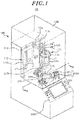
- the automated experiment apparatus 10 may include a housing 100, a pressure vessel 200 provided inside the housing 100 and including a sample receiving chamber 220 (see Fig. 2 ), and a clamp 300 configured to selectively air-tightly fix a sample holding member 120 and the pressure vessel 200.
- the housing 100 provides an outer shell of the automated experiment apparatus 10.
- the pressure vessel 200 is installed inside the housing 100.
- the automated experiment apparatus 10 may further include a display 104 disposed on the housing 100 and configured to display the current state of the apparatus 10 or other information to an user, and a user interface 106 disposed on the housing 100 and configured to receive an input from the user, generate an input signal and send it to a controller 400 shown in Fig. 7 .
- a transparent window 108 is configured to cover an upper portion of the housing 100.
- the window 108 functions as a safety shield curtain capable of preventing leakage of a gas to the outside.
- the user interface 106 is positioned outside of the transparent window 108. While not shown in the drawings, a fan for discharging a gas may be installed inside the housing 100.
- the sample holding member 120 configured to hold a sample P to be accommodated within the sample receiving chamber 220 and selectively cover an upper end opening 202 of the pressure vessel 200. Further, in the housing, there are provided a moving unit 110 configured to vertically move the sample holding member 120, a gas transfer unit 130 connected to the sample holding member 120 and configured to transfer a gas into the pressure vessel 200 and a sensing unit 140.
- the moving unit 110 is configured to vertically move the sample holding member 120 and provided on the front side of the housing 100.
- the moving unit 110 includes a lifter 112 configured to provide a driving force to move the sample holding member 120 vertically, a guide 114 configured to guide the vertical movement of the sample holding member 120, and a moving frame 116 connected to the sample holding member 120 and the lifter 112 and configured to be moved vertically by the lifter 112.
- the guide 114 is attached on the front side surface of the housing and extends vertically.
- the moving frame 116 is engaged with the guide 114. The vertical movement of the moving frame 116 is guided by the guide 114.
- the lifter 112 is, for example, a hydraulic cylinder or a screw jack.
- any suitable member which can provide a driving force for vertically moving the sample holding member 120 may be used as the lifter 112.
- the guide 114 may be one or more bars installed on a wall surface of the housing 100 and formed to extend in a vertical direction.
- the moving frame 116 may have a bar shape and extend horizontally. The moving frame 116 is guided by the guide 114 when the lifter 112 is driven.
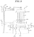
- the sample holding member 120 may be vertically moved between an upper position and a lower position by the moving unit 110, as shown in Fig. 3 .
- the term "upper position” used herein refers to the uppermost position to which the sample holding member 120 can be moved up with respect to the housing 100.
- the term “lower position” used herein refers to the lowermost position to which the sample holding member 120 can be moved down with respect to the housing 100.
- the sample holding member 120 may include a holder flange 122 configured to make contact with the pressure vessel 200 at the lower position, a connection frame 124 configured to interconnect the moving frame 116 and the holder flange 122, and a sample holder 126 connected to the holder flange 122 and configured to hold the sample P.
- the holder flange 122 is formed in a lower portion of the sample holding member 120.
- the holder flange 122 has a circular outer shape of the same radius as a vessel flange 210 of the pressure vessel 200.
- the connection frame 124 may extend from the upper surface of the sample holding member 120 and be connected to the center of the moving frame 116.
- the sample holder 126 is configured to hold the sample P provided as test tubes for accommodating a reactant therein.
- the sample holder 126 may include an upper disc having a plurality of holes into which the test tubes can be inserted, a lower disc having a plurality of recesses formed on an upper surface thereof and configured to accommodate the lower portions of the test tubes, and a central beam configured to interconnect the upper disc and the lower disc.
- the sample P may be held in the sample holder 126 as the test tubes are inserted into the holes of the upper disc and the lower portions of the test tubes are accommodated in the recesses of the lower disc.
- the gas transfer unit 130 is configured to supply the gas, for example, a N 2 gas, into the pressure vessel 200.
- the gas transfer unit 130 includes a gas supplier 132 configured to supply the gas into the pressure vessel 200, a gas discharger 136 configured to discharge the gas from the pressure vessel 200, a gas supply line 134 connected at the opposite ends to the sample holding member 120 and the gas supplier 132, and a gas discharge line 138 connected at the opposite ends to the sample holding member 120 and the gas discharger 136.
- the gas supplier 132 and the gas discharger 136 may include a gas transfer means, and the gas transfer means is for example, a blower fan 105 (see Fig. 12 ) provided inside the housing 100.
- the gas supplier 132 may further include a separate storage container configured to store a specified gas to be supplied.
- the gas transfer means may be connected to the storage container so that the gas stored in the storage container can be supplied into the pressure vessel 200 via the gas supply line 134.
- the gas discharger 136 may further include a separate post-treatment means.
- the gas transfer means may be connected to the post-treatment means so that the gas existing in the pressure vessel 200 can be discharged to the post-treatment means via the gas discharge line 138.
- the gas supplier 132 and the gas discharger 136 may be provided inside the housing 100. However, the present disclosure is not limited thereto.
- the gas supplier 132 and the gas discharger 136 may be separately provided outside the housing 100 and may be connected to the gas supply line 134 and the gas discharge line 138.
- the gas supply line 134 and the gas discharge line 138 are connected at one end to the sample holding member 120 and are formed to extend to the lower surface of the sample holding member 120 through the sample holding member 120.
- the gas supply line 134 and the gas discharge line 138 communicate with the sample receiving chamber 220 inside the pressure vessel 200 when the sample holding member 120 is fastened to the pressure vessel 200 in an air-tight manner.
- the sensing unit 140 includes an upper position sensor 142 configured to sense whether the sample holding member 120 is located at the upper position, a lower position sensor 144 configured to sense whether the sample holding member 120 is located at the lower position, a pressure sensor 146 configured to measure an internal pressure of the pressure vessel 200, and a temperature sensor 148 configured to measure an internal temperature of the pressure vessel 200.
- the upper position sensor 142 and the lower position sensor 144 are respectively installed in a position corresponding to the upper position of the moving frame 116 and a position corresponding to the lower position of the moving frame 116.
- the upper position sensor 142 and the lower position sensor 144 may be, for example, a magnetic sensor.
- the pressure vessel 200 which is a cylindrical container, may be made of a material capable of resisting a high temperature and a high pressure.
- the pressure vessel 200 has an opening 202 formed in the upper surface thereof.
- An inner lining 204 of the pressure vessel 200 is made of a rigid material having a superior heat resistance such as Teflon which has superior heat and acid resistance.
- the pressure vessel 200 further includes the vessel flange 210 provided as the upper end portion of the pressure vessel 200 so as to surround the opening 202.
- the vessel flange 210 has a circular outer shape with a radius about a central axis 201 of the pressure vessel 200.
- the pressure vessel 200 further includes a heating unit 230 configured to heat the sample receiving chamber 220, and a cooling unit 240 configured to cool the sample receiving chamber 220 by circulating a coolant along the periphery of the sample receiving chamber 220.
- the heating unit 230 may include a microwave generator 232 configured to generate a microwave, a magnetron 234 configured to transfer the microwave generated in the microwave generator 232 to the sample receiving chamber 220, and an antenna 236 connected to the sample receiving chamber 220 and configured to transmit the microwave guided by the magnetron 234 to the sample receiving chamber 220.
- the cooling unit 240 may include a coolant supplier 242 configured to store and supply a coolant.
- a coolant inlet 244 for supplying the coolant to a coolant circulation line connected to the coolant supplier 242 and provided to surround the outer surface of the pressure vessel 200 and a coolant outlet 246 for recovering the coolant discharged from the coolant circulation line.
- the clamp 300 is provided to selectively air-tightly engage the holder flange 122 of the sample holding member 120 and the vessel flange 210 of the pressure vessel 200.
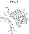
- the clamp 300 may include a clamp body 320, a clamp head 310 and an actuator 330 connected to the clamp head 310.
- the clamp head 310 includes a groove 312 configured to engage with the holder flange 122 and the vessel flange 210.
- the actuator 330 actuates the clamp head 310 to make the clamp head move in a radial direction of the vessel flange 210.
- the groove 312 When the clamp head 310 moves toward the vessel flange 210 and the holder flange 122, the groove 312 is engaged with the holder flange 122 and the vessel flange 210 together so that the holder flange 122 and the vessel flange 210 are air-tightly fixed to each other.
- the groove 312 When the clamp head 310 moves back from the vessel flange 210 and the holder flange 122, the groove 312 is disengaged from the holder flange 122 and the vessel flange 210 so that the holder flange 122 and the vessel flange 210 are not fixed to each other.
- the actuator 330 may be one of a hydraulic cylinder, a screw jack or the like.
- the holder flange 122 and the vessel flange 210 may have a ring shape and the clamp head 310 may have an arc shape.
- the clamp 300 may be a C-type clamp as the groove 312 has a C-like vertical cross section.
- the vertical cross section of the groove 312 may be defined by a vertical surface 312b and two slant surfaces 312a formed to obliquely extend from the upper and lower ends of the vertical surface 312b.
- Slant surfaces are also formed in the edge portions of the holder flange 122 and the vessel flange 210 that correspond to the slant surfaces 312a of the clamp 300.
- the clamp head 310 In a state in which the slant surfaces of the holder flange 122 and the vessel flange 210 and the slant surfaces 312a of the clamp 300 are brought into contact with each other, the clamp head 310 further moves toward the holder flange 122 and the vessel flange 210, thereby compressing the holder flange 122 and the vessel flange 210 against each other. In this manner, the holder flange 122 and the vessel flange 210 can be air-tightly sealed.
- a clamping sensor 322 configured to sense the position of the clamp head 310 may be provided to the clamp body 320.
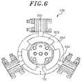
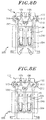
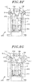
- the clamping sensor 322 is capable of accurately sensing a top dead point of the clamp head 310, at which the clamp head 310 is fully pushed out from the clamp body 320 by the actuator 330, as shown in Fig. 6 , and a bottom dead point of the clamp head 310, at which the clamp head 310 is fully pulled into the clamp body 320 by the actuator 330, as shown in Fig. 5 .
- the clamping sensor 322 may be a magnetic sensor.
- a contact point provided in the end portion of a piston rod connected to the clamp head 310 is brought into contact with a magnet disposed in a relevant position inside the clamp body 320, whereby an electric current flows through the contact point.
- An electrical signal thus generated is transmitted to the sensor signal receiving unit 414 (see Fig. 7 ) so that the position of the moving frame 116 can be detected.
- one or more clamps 300 are disposed around the opening 202 of the pressure vessel 200 and the clamp heads 310 thereof are configured to move toward or away from the pressure vessel 200. If a plurality of clamps 300 are provided, the clamps 300 are disposed around the pressure vessel 200 at predetermined intervals so that a plurality of the clamp heads 310 can make contact with the holder flange 122 and the vessel flange 210 at multiple points.
- the clamp heads 310 are configured to move toward or back from the holder flange 122 and the vessel flange 210, thereby air-tightly fixing or unfixing the sample holding member 120 and the pressure vessel 200.
- an elastic O-ring may be provided on the mutually-facing surface of the holder flange 122 and/or the vessel flange 210.
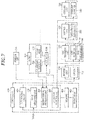
- the controller 400 is configured to automatically perform a reaction process under a predetermined temperature and pressure in a state in which the sample holding member 120 is air-tightly fixed to the pressure vessel 200 and a sample P is accommodated within the sample receiving chamber 220.
- the controller 400 comprises an interfacing circuit 410, a memory 420 and a processor 430.
- the interfacing circuit 410 is coupled to the processor 430, and the memory 420 is coupled to the processor 430.
- the interfacing circuit 410 comprises an input receiving unit 412 configured to receive an input through the user interface 106, a sensor signal receiving unit 414 configured to receive sensor signals from various sensors including the upper position sensor 142, the lower position sensor 144, the pressure sensor 146, the temperature sensor 148 and the clamping sensor 322, and an operation control unit 416 coupled to the lifter 112 of the moving unit 110, the gas supplier 132 and the gas discharger 136 of the gas transfer unit 130, the microwave generator 232 of the heating unit 230, the coolant supplier 242 of the cooling unit 240 and the actuator 330 of the clamp 300.
- the upper position sensor 142 is coupled to the sensor signal receiving unit 414 and configured to send a sensing signal of whether the sample holding member 120 is located at the upper position to the sensor signal receiving unit 414.
- the lower position sensor 144 is coupled to the sensor signal receiving unit 414 and configured to send a sensing signal of whether the sample holding member 120 is located at the lower position to the sensor signal receiving unit 414.
- the pressure sensor 146 is coupled to the sensor signal receiving unit 414 and configured to send a sensing signal of the internal pressure of the pressure vessel 200 to the sensor signal receiving unit 414.
- the temperature sensor 148 is coupled to the sensor signal receiving unit 414 and configured to send a sensing signal of the internal temperature of the pressure vessel 200 to the sensor signal receiving unit 414.
- the operation control unit 416 is configured to send a control signal to the lifter 112 to move the moving frame vertically.
- the operation control unit 416 is further configured to send a control signal to the gas supplier 132 and the gas discharger 136 for supplying/discharging the gas into/from the pressure vessel 200.
- the operation control unit 416 is further configured to send a control signal to the microwave generator 232 for heating the pressure vessel 200.
- the operation control unit 416 is further configured to send a control signal to the coolant supplier 242 for cooling the pressure vessel 200.
- the operation control unit 416 is further configured to send a control signal to the actuator 330 to move the moving frame 116 vertically.
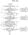
- the automated experiment method is started by a start signal input from an user through the user interface 106.
- the user may input specific reaction conditions such as a reaction temperature, a reaction pressure and a reaction time. These reaction conditions may be pre-stored in the memory 420.
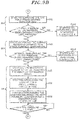
- the input receiving unit 412 of the controller 400 receives the start signal (S11). As the input receiving unit 412 receives the start signal, the controller 400 sends a control signal to the lifter 112 to move the sample holding member 120 down to the lower position.
- the controller 400 may determine whether the sample holding member 120 is sensed by the upper position sensor 142 (S12). If the upper position sensor 142 senses the sample holding member 120 being properly located at the upper position, the controller 400 sends a control signal to the lifter 112 and the lifter 112 is driven to move the sample holding member 120 downward (S14).
- the controller 400 stops all operations of the automated experiment apparatus 10 and generates alarm code 1 (S122).
- S122 alarm code 1
- the lifter 112 is controlled by the controller 400 to accurately generate a driving force at a predetermined magnitude and move the sample holding member 120 down to the lower position.
- the controller 400 verifies whether the sample holding member 120 is sensed by the lower position sensor 144 during a first preset time after the controller 400 sends a control signal to the lifter 112 to move down the sample holding member 120 (S16). If the lower position sensor 144 senses the sample holding member 120 being properly located at the lower position, the controller 400 sends control signals to the plurality of actuators 330.
- the controller 400 stops all operations of the automated experiment apparatus 10 and generates alarm code 2 (S162). This makes it possible to prevent damage or erroneous operation of the apparatus which may occur when the holder flange 122 and the vessel flange 210 are clamped in a state in which the sample holding member 120 is not properly positioned at the lower position due to an unexpected error despite the provision of the predetermined driving force.
- the controller 400 sends control signals to the plurality of actuators 330, and the clamp heads 310 move transversely toward the holder flange 122 and the vessel flange 210 to engage the holder flange 122 and the vessel flange 210 (S2).
- the sample holding member 120 and the pressure vessel 200 are air-tightly fixed to each other.
- each of the clamp heads 310 of the clamps 300 begins to be pushed out from the corresponding clamp bodies 320 (S22).
- the clamps 300 are controlled to be operated synchronously.
- the actuators 330 can be controlled to be stretched to a predetermined length.
- the controller 400 verifies whether the clamp head 310 is sensed to be located at the top dead point by the clamping sensors 322 during a second preset time after the controller 400 sends control signals to the actuators 330 for stretching thereof (S24). If the clamping sensors 322 senses the clamp heads 310 at the top dead point, it is considered that the sample holding member 120 and the pressure vessel 200 have been air-tightly fixed completely.
- the controller 400 stops all operations of the automated experiment apparatus 10 and generates alarm code 3 (S242). This makes it possible to prevent damage of the apparatus or leakage of a harmful gas, which may occur when the clamp heads 310 are not located at the predetermined top dead point due to an unexpected error and when a reaction is started in a state in which the air-tight fixing of the holder flange 122 and the vessel flange 210 by clamping is not fully achieved.
- the gas supplier 132 is operated to supply a specified gas to the sample receiving chamber 220 (S3) after the clamping step (S2) is completed.
- the operation of the gas supplier 132 may be started to supply a specified gas into the pressure vessel 200 for a predetermined period of time (S32).
- the gas may be, for example, an N 2 gas.
- the supply of the gas using the gas supplier 132 may be performed until the internal pressure of the pressure vessel 200 reaches a predetermined reaction pressure.
- the amount of the supply gas required for creating the predetermined reaction pressure may be automatically calculated according to an algorithm stored in the controller 400.
- the amount of the gas thus calculated may be supplied into the pressure vessel 200 via the gas supply line 134.
- the controller 400 determines whether the internal pressure of the pressure vessel 200 measured by the pressure sensor 146 is higher than a pressure limit (S34).
- the controller 400 may stop all operations of the automated experiment apparatus 10 and may generate alarm code 4 (S342). This makes it possible to prevent breakage of the pressure vessel 200 which may occur when the internal pressure exceeds the pressure limit due to an unexpected error.
- a heating step (S4) for heating the sample receiving chamber 220 is started.
- the operation of the microwave generator 232 is started to transfer a microwave to the pressure vessel 200 via the antenna 236 for a predetermined period of time (S42).
- the internal temperature of the pressure vessel 200 gets higher.
- the interior of the pressure vessel 200 may be heated so that the internal temperature of the pressure vessel 200 reaches a predetermined reaction temperature.
- the amount of the microwave required for achieving the predetermined reaction temperature may be automatically calculated according to a specified algorithm stored in the controller 400.
- the controller 400 may determine whether the internal temperature of the pressure vessel 200 measured by the temperature sensor 148 reaches a predetermined temperature limit(S44).
- the temperature limit may be set at a temperature above which explosion may occur inside the pressure vessel 200 by the sample P or a temperature above which other components inside the pressure vessel 200 may be damaged.
- the controller 400 may stop all operations of the automated experiment apparatus 10 and may generate alarm code 5 (S442). After the heating step (S4) is completed and the reaction is terminated, the sample receiving chamber 220 is cooled by circulating a coolant through a circumference of the pressure vessel 200, and the gas is discharged from the sample receiving chamber 220 (S5).
- the reaction is terminated as the operation of the microwave generator 232 is stopped (S52).
- the coolant supplier 242 starts to operate and the coolant is supplied to and circulated along the periphery of the pressure vessel 200 for a predetermined period of time (S54).
- the operation of the gas discharger 136 is started and the gas is discharged from the pressure vessel 200 via the gas discharge line 138 for a predetermined period of time (S56).
- the gas may be discharged until the internal pressure of the pressure vessel 200 reaches the atmospheric pressure (1 atm). This makes it possible to prevent the occurrence of unnecessary explosions when the pressure vessel 200 is opened (S58).
- the holder flange 122 and the vessel flange 210 are unclamped (S6) after the cooling and gas discharging step (S5) is completed.
- each of the clamp heads 310 of the clamps 300 begin to be pulled into the corresponding clamp bodies 320 (S62).
- the clamps 300 are controlled to be operated synchronously.
- the actuators 330 can be controlled to be shrunk to a predetermined length.
- the controller 400 verifies whether the clamp head 310 is sensed to be located at the bottom dead point by the clamping sensors 322 during a third preset time after the controller 400 sends control signals to the actuators 330 for shrinking thereof (S64). If the clamping sensors 322 senses the clamp heads 310 at the bottom dead point, it is considered that the sample holding member 120 and the pressure vessel 200 have been unfixed completely.
- the controller 400 stops all operations of the automated experiment apparatus 10 and generates alarm code 6 (S642). This makes it possible to prevent damage or erroneous operation of the apparatus which may occur when the clamp head 310 is not located at the predetermined bottom dead point due to an unexpected error and when the upward movement of the sample holding member 120 is started in a state in which the unclamping of the holder flange 122 and the vessel flange 210 is not fully achieved.
- the sample holding member 120 is moved up to the upper position by the lifter 112 (S7).
- the controller 400 controls the lifter 112 to move the sample holding member 120 upward (S72).
- the lifter 112 is controlled by the controller 400 to accurately generate a driving force at a predetermined magnitude and move the sample holding member 120 up to the upper position.
- the controller 400 verifies whether the sample holding member 120 is sensed by the upper position sensor 142 during a fourth preset time after the controller 400 sends a control signal to the lifter 112 to move up the sample holding member 120 (S74). If the upper position sensor 142 senses the sample holding member 120 being properly located at the upper position, the automated experiment process is completed.
- the controller 400 stops all of the operations of the automated experiment apparatus 10 and generates alarm code 7 (S742). This makes it possible to prevent the erroneous operation of the apparatus which may occur when the next experiment is initiated in a state in which the sample holding member 120 is not properly positioned at the upper position due to an unexpected error despite the provision of the predetermined driving force.
- FIGs. 1 and 7 show the gas transfer unit 130 connected to the sample holding member 120.
- the gas supplier 132 and the gas discharger 136 of the gas transfer unit 130 are connected to the sample holding member 120 via the gas supply line 134 and the gas discharge line 138, respectively, and the gas supply line 134 and the gas discharge line 138 are arranged to go inside the housing 100.
- the gas supply line 134 and the gas discharge line 138 are arranged to go inside the housing 100.
- gas lines disposed in the housing 100 are corroded, it would be difficult for an ordinary user to fix the same.
- the automated experiment apparatus 10 may employ a gas control module 500 detachably accommodated in the housing 100, making it easy for an unskilled person to replace gas pipes constituting a part of the gas supply line 134 and the gas discharge line 138.
- a gas control module 500 detachably accommodated in the housing 100, making it easy for an unskilled person to replace gas pipes constituting a part of the gas supply line 134 and the gas discharge line 138.
- the gas control module 500 is detachably accommodated in the housing 100 and includes gas pipes constituting a part of the gas supply line 134 and the gas discharge line 138 which provide flow paths for the gas supplied to or discharged from the pressure vessel 200. Further, the gas control module 500 also includes various valve devices for controlling a supply path or a discharge path of the gas.
- the gas control module 500 includes a base panel 502, a connecting block 510 connected at one side of the base panel 502, a gas input valve 520 configured to open or close the gas supply line 134, a gas output valve 530 configured to open or close the gas discharge line 138 and a relief valve 540 configured to open a bypass line for a rapid discharging of the gas when the pressure inside the pressure vessel 200 reaches or exceeds the pressure limit.
- a space for accommodating the gas control module 500 is formed inside the housing 100 and an inner hole 101 (see, Fig. 12 ) communicating with a lower portion of the housing 100 is formed at the bottom surface of said space.
- various lines and connectors extended from the gas control module 500 pass through this inner hole 101, such as an input connector 522 and an output connector 524 respectively extended from the gas supply line 134 and the gas discharge line 138.
- the input connector 522 and the output connector 524 are connected to connection ports (not shown) of the pressure vessel 200 within the housing 100.
- the space in the housing 100 where the gas control module 500 is received may be covered by a back cover 103.
- the back cover 103 is configured to open said space of the housing 100 when the gas control module 500 is being installed in or detached from the housing 100.
- the base panel 502 is provided to support pipes for supplying or discharging the gas and may be fixed to the housing 100 by bolts and nuts. Alternatively, the base panel 502 may be detachably attached to the housing 100 and the detaching or attaching of the base panel 502 is guided by the connecting block 510 attached at one side of the base panel 502.
- the connecting block 510 is inserted to a connecting groove 102 concavely formed from an edge of a wall of the housing 100 and determines an installing position of the base panel 502. Accordingly, it is easy even for an unskilled person to open the back cover 103 and attach or detach the base panel 502 to or from the housing 100.
- a manual valve 512, an emergency valve 514 and a gas input port 516 are provided to the connecting block 510.
- the manual valve 512 may be provided for adjusting a pressure of the gas supplied from the gas supplier 132 such as a gas bombe in a laboratory when the automated experiment apparatus 10 is initially set up in the laboratory.
- an initial pressure gauge 504 may be provided to the base panel 502, and the initial pressure gauge 504 is connected to the manual valve 512 so that an installer can check the pressure of the gas when adjusting the initial pressure of the gas. After the initial adjustment of the pressure of the gas is finished, the manual valve 512 may not be touched during the normal operation.
- the emergency valve 514 may be used to manually discharge the gas from the pressure vessel 200 when an alarm is generated by the controller 400 during the experiment.
- the emergency valve 514 is configured to manually open or close a bypass line bypassing the gas output valve 530.
- the gas input port 516 is configured to be engaged with the gas supply line 134 extended from the gas supplier 132. Further, a line is extended from the gas input port 516 to the pressure vessel 200.
- the gas input valve 520 is installed to the base panel 520 and configured to be provided on the gas supply line 134 when the gas control module 500 is installed in the housing 100.
- the gas input valve 520 is provided on the line extended from the gas input port 516 so as to open or close the gas supply line 134 and configured to be controlled by the controller 400.
- the gas input valve 520 may be a solenoid valve that is electrically connected to the controller 400.
- the input connector 522 is provided at an end of the line on which the gas input valve 520 is provided.
- the input connector 522 is connected to an input line extended from the sample holding member 120.
- the check valve 526 is provided between the gas input valve 520 and the input connector 522, to prevent a gas reflux toward the gas input valve 520.
- the gas output valve 530 may be attached to the base panel 502 and located in the middle of the gas discharge line 138 when the gas control module 500 is installed in the housing 100.
- the gas output valve 530 is provided on the gas discharge line 138 which is extended from the sample holding member 120 and connected to the blower fan 105.
- the gas output valve 530 is configured to open or close the gas discharge line 138 and the controller 400 is configured to control the gas output valve 530.
- the gas discharge valve 530 may be a solenoid valve that is electrically connected to the controller 400.
- the relief valve 540 may be attached to the base panel 502 and located in the middle of the bypass line bypassing the gas output valve 530 when the gas control module 500 is installed in the housing 100. Further, the relief valve 540 is configured to open the bypass line only at a pressure exceeding a preset pressure limit such as 200 bars. As a result, if the pressure of the gas inside the pressure vessel 200 or the gas discharge line 138 exceeds the pressure limit, the relief valve 540 is configured to be automatically opened and the gas is discharged therefrom through the relief valve 540. Consequently, an accident can be prevented by opening of the relief valve 540 even when the user failed to open the emergency valve 514.
- the relief valve 540 can be preset to be opened under a pressure higher than the pressure limit at which the alarm will be also generated by the controller 400.
- the gas discharge line 138 extended from the sample holding member 120 and connected to the blower fan 105 includes at least three junctions 532, 534, 536 so that the gas discharge line 138 is separated into at least three branches inside the housing 100.
- a first junction 532 is a junction from which a line with the emergency valve 514 provided thereon is branched off and a second junction 534 is positioned on a downstream line of the first junction 532.
- the second junction 534 is a junction from which a line with the gas output valve 530 provided thereon and a line with the relief valve 540 provided thereon are branched off.
- the third junction 536 is where the three lines with the emergency valve 514, the gas output valve 530 and the relief valve 540 respectively provided thereon all join together.
- a line extended from the third junction 536 is connected to the blower fan 105 so that the gas is discharged by the blower fan 105.
- the blower fan 105 is connected to a discharge port 107 formed through a wall of the housing 100 to discharge the gas from the housing 100.
- a regular pressure gauge 506 may be provided on the base panel 502 for manually checking the pressure of the gas inside the pressure vessel 200 during the operation of the automated experiment apparatus 10.
- the regular pressure gauge 506 is connected to a line branched from the middle of a line connecting the second junction 534 and the relief valve 540 so that the pressure inside the pressure vessel 200 can be shown by the regular pressure gauge 506.
- the emergency valve 514 and the relief valve 540 are closed, and discharging of the gas is controlled by the gas output valve 530. Further, when the pressure inside the pressure vessel 200 increases over the pressure limit, an alarm is generated, and the user can manually manipulate the emergency valve 514 to discharge the gas from the pressure vessel 200 or the relief valve 540 is automatically opened to discharge the gas.
- the steps for installing the gas control module 500 having aforementioned configurations into the housing 100 will be described.
- the back cover 103 can be opened.
- the connecting block 510 can be simply inserted into the connecting groove 102.
- the base panel 502 can be fixed to the housing 100 by bolts.
- the input connector 522 and the output connector 524 can be connected to the sample holding member 120 or lines extended from the sample holding member 120.
- the third junction 536 can be connected to the blower fan 105 via a tube and the back cover 103 can be closed.
- the resultant values detected by various kinds of sensors are utilized during the course of the automated experiment process.
- the process is stopped and different alarm codes are generated depending on the situation. This enables the user to recognize the situation and to take an appropriate measure. It is therefore possible to prevent irrecoverable damage or erroneous operation of the apparatus.
Landscapes
- Chemical & Material Sciences (AREA)
- Chemical Kinetics & Catalysis (AREA)
- Organic Chemistry (AREA)
- Health & Medical Sciences (AREA)
- Physics & Mathematics (AREA)
- Clinical Laboratory Science (AREA)
- Electromagnetism (AREA)
- General Health & Medical Sciences (AREA)
- Analytical Chemistry (AREA)
- Automation & Control Theory (AREA)
- Engineering & Computer Science (AREA)
- General Physics & Mathematics (AREA)
- Toxicology (AREA)
- Sampling And Sample Adjustment (AREA)
Claims (18)
- Automatisierte Versuchseinrichtung, umfassend:ein Druckgefäß (200), das eine Öffnung aufweist, um eine Probenaufnahmekammer (220) in demselben zu definieren, wobei das Druckgefäß einen Gefäßflansch (210) einschließt, der eine kreisrunde Außenform mit einem Radius um eine Mittelachse des Druckgefäßes aufweist;ein Probenhalteelement (120), das dazu konfiguriert ist, eine Probe zu halten, die in der Probenaufnahmekammer (220) untergebracht werden soll, wobei das Probenhalteelement einen Halterflansch (122) einschließt, der eine kreisrunde Außenform desselben Radius wie der Gefäßflansch (210) aufweist und dazu konfiguriert ist, Kontakt mit dem Gefäßflansch herzustellen, um die Öffnung zu verschließen;eine Erfassungseinheit (140), die dazu konfiguriert ist, mindestens eine aus einer oberen Position und einer unteren Position des Probenhalteelements (120) zu erfassen;eine Vielzahl von Klemmen (300), die dazu konfiguriert sind, luftdicht mit dem Halterflansch (122) des Probenhalteelements (120) und dem Gefäßflansch (210) des Druckgefäßes (200) einzugreifen, wobei jede aus der Vielzahl von Klemmen einen Klemmenkopf (310), der eine Nut (312) aufweist, die dazu konfiguriert ist, mit dem Halterflansch und dem Gefäßflansch einzugreifen, und einen Aktor (330) einschließt, der mit dem Klemmenkopf verbunden ist;einen Klemmsensor (322), der dazu konfiguriert ist, einen oberen Totpunkt des Klemmenkopfes (310) zu erfassen, bei dem der Klemmenkopf (310) vom Aktor (330) vollständig herausgedrückt ist, um luftdicht mit dem Halterflansch (122) einzugreifen;eine Gastransfereinheit (130), die eine Gaszuführung (132) und eine Gasabführung (136) umfasst, die mit dem Probenhalteelement (120) verbunden und dazu konfiguriert sind, ein Gas in das Druckgefäß (200) zuzuführen oder aus demselben abzuführen;eine Heizeinheit (230), die dazu konfiguriert ist, die Probenaufnahmekammer (220) zu erhitzen;einen Drucksensor (146), der dazu konfiguriert ist, einen Innendruck des Druckgefäßes (200) zu messen;eine Benutzerschnittstelle (106), die dazu konfiguriert ist, eine Eingabe von einem Benutzer zu empfangen; undeine Steuerung (400), die dazu konfiguriert ist, ein Eingangssignal von der Benutzerschnittstelle (106) und ein Erfassungssignal von der Erfassungseinheit (140) zu empfangen, um in Antwort auf das Eingangssignal und das Erfassungssignal den Aktor (330) jeder der Klemmen (300) so zu steuern, dass der Klemmenkopf (310) dazu gebracht wird, eine Querbewegung in einer radialen Richtung des Gefäßflansches (210) vorzunehmen, um mit dem Halterflansch (122) und dem Gefäßflansch (210) einzugreifen, in Antwort auf ein Klemmsensorsignal, das aus dem Klemmsensor (322) empfangen wird, die Gastransfereinheit (130) so zu steuern, dass dem Druckgefäß (200) das Gas zugeführt wird, bis der Innendruck des Druckgefäßes (200) einen vorbestimmten Reaktionsdruck, wie von einem Drucksensorsignal aus dem Drucksensor (146) angezeigt, erreicht, in Antwort auf das Drucksensorsignal aus dem Drucksensor (146) die Heizeinheit (230) so zu steuern, dass die Probenaufnahmekammer (220) erhitzt wird, und die Gastransfereinheit (130) so zu steuern, dass das Gas aus der Probenaufnahmekammer (220) abgeführt wird.
- Einrichtung nach Anspruch 1, wobei die Steuerung (400) umfasst:einen Prozessor (430),einen Speicher (420), der mit dem Prozessor gekoppelt ist, undeine Schnittstellenschaltung (410), die mit dem Prozessor gekoppelt ist, wobei die Schnittstellenschaltung weiter mit der Benutzerschnittstelle (106) und der Erfassungseinheit (140) gekoppelt ist, um das Eingangssignal und das Erfassungssignal von denselben zu empfangen, wobei die Schnittstellenschaltung ebenfalls mit dem Klemmsensor (322), um ein Sensorsignal von demselben zu empfangen, und dem Aktor (330) jeder der Klemmen gekoppelt ist, um Steuersignale an die Aktoren zu senden, um Betriebsvorgänge der Aktoren zu steuern.
- Einrichtung nach Anspruch 2, weiter umfassend:einen Heber (112);einen beweglichen Rahmen (116), der mit dem Probenhalteelement (120) und dem Heber (112) verbunden ist; undeine Führung (114), die dazu konfiguriert ist, Bewegung des beweglichen Rahmens zu führen,wobei die Schnittstellenschaltung (410) dazu konfiguriert ist, ein Steuersignal an den Heber (112) zu senden, um den beweglichen Rahmen (116) vertikal zu bewegen.
- Einrichtung nach Anspruch 2 oder 3,
wobei die Schnittstellenschaltung (410) dazu konfiguriert ist, ein Steuersignal an die Gaszuführung zu senden, um der Probenaufnahmekammer das Gas zuzuführen, und
wobei die Schnittstellenschaltung (410) dazu konfiguriert ist, ein Steuersignal an die Gasabführung zu senden, um das Gas aus der Probenaufnahmekammer abzuführen. - Einrichtung nach Anspruch 2, 3 oder 4, wobei die Erfassungseinheit (140) einen oberen Positionssensor (142), der dazu konfiguriert ist, zu erfassen, ob sich das Probenhalteelement (120) an der oberen Position befindet, und einen unteren Positionssensor (144) umfasst, der dazu konfiguriert ist, zu erfassen, ob sich das Probenhalteelement an der unteren Position befindet,
wobei der obere Positionssensor (142) mit der Sensorsignal-Empfangseinheit (414) gekoppelt und dazu konfiguriert ist, ein Erfassungssignal desbezüglich, ob sich das Probenhalteelement an der oberen Position befindet, an die Sensorsignal-Empfangseinheit zu senden, und
wobei der untere Positionssensor (144) mit der Sensorsignal-Empfangseinheit (414) gekoppelt und dazu konfiguriert ist, ein Erfassungssignal desbezüglich, ob sich das Probenhalteelement an der unteren Position befindet, an die Sensorsignal-Empfangseinheit zu senden. - Einrichtung nach einem der Ansprüche 2 bis 5, wobei die Steuerung (400) dazu konfiguriert ist, einen Reaktionsprozess automatisch unter einer vorbestimmten Temperatur und einem vorbestimmten Druck auszuführen, wenn das Probenhalteelement (120) luftdicht am Druckgefäß (200) befestigt ist.
- Einrichtung nach einem vorstehenden Anspruch, wobei der Halterflansch (122) und der Gefäßflansch (210) eine Ringform aufweisen, und die Nut (312) einen C-artigen vertikalen Querschnitt aufweist.
- Einrichtung nach einem vorstehenden Anspruch, wobei ein vertikaler Querschnitt der Nut (312) von einer vertikalen Fläche (312b) und zwei Neigungsflächen (312a) definiert wird, die so gebildet sind, dass sie sich jeweils von oberen und unteren Enden der vertikalen Fläche (312b) erstrecken.
- Einrichtung nach einem vorstehenden Anspruch, weiter umfassend:ein Gehäuse (100), in dem das Druckgefäß (200) bereitgestellt ist; undein Gassteuermodul (500), das abnehmbar im Gehäuse untergebracht ist,wobei das Gassteuermodul (500) umfasst:eine Grundplatte (502), die Rohre zum Zuführen des Gases zu, oder Abführen des Gases aus dem Druckgefäß (200) trägt, wobei die Grundplatte (502) abnehmbar am Gehäuse (100) untergebracht ist;einen Verbindungsblock (510), der auf einer Seite der Grundplatte angebracht ist;ein Gaseingangsventil (520), das auf der Grundplatte bereitgestellt ist, um eine Gaszuführleitung (134) zum Zuführen des Gases zum Druckgefäß zu öffnen oder zu schließen; undein Gasausgangsventil (530), das auf der Grundplatte bereitgestellt ist, um eine Gasabführleitung (138) zum Abführen des Gases aus dem Druckgefäß zu öffnen oder zu schließen.
- Einrichtung nach Anspruch 9, wobei der Verbindungsblock (510) in eine Verbindungsnut (102) eingesetzt ist, die an einer Kante einer Wand des Gehäuses (100) vertieft ist,
wobei der Verbindungsblock (510) eine Position der Grundplatte (502) bestimmt, wenn das Gassteuermodul (500) im Gehäuse untergebracht ist. - Einrichtung nach Anspruch 9 oder 10, wobei das Gassteuermodul (500) weiter ein Entlastungsventil (540) umfasst, das auf der Grundplatte (502) bereitgestellt ist und automatisch geöffnet wird, wenn ein Druck im Druckgefäß (200) gleich oder höher als ein vorbestimmter Druck ist,
wobei am Verbindungsblock (510) ein Notventil (514) bereitgestellt ist, das dazu konfiguriert ist, manuell betätigt zu werden, und sich an einer Mitte der Gasabführleitung (138) befindet, und
wobei die Gasabführleitung mindestens drei Zweige (532, 534, 536) im Gassteuermodul einschließt, und
wobei das Notventil (514), das Gasausgangsventil (530) und das Entlastungsventil (540) jeweils an jedem der drei Zweige bereitgestellt sind. - Automatisiertes Versuchsverfahren unter Verwendung einer automatisierten Versuchseinrichtung, umfassend:Bewegen eines Probenhalteelements (120) der automatisierten Versuchseinrichtung nach unten, um einen Halterflansch (122) der automatisierten Versuchseinrichtung mit einem Gefäßflansch (210) der automatisierten Versuchseinrichtung in Kontakt zu bringen, indem in Antwort auf ein von einer Steuerung (400) der automatisierten Versuchseinrichtung gesendetes Steuersignal ein Heber (112) angetrieben wird, wobei das Probenhalteelement (120) dazu konfiguriert ist, eine Probe zu halten, die in einer Probenaufnahmekammer (220) der automatisierten Versuchseinrichtung untergebracht werden soll;Ineingriffbringen des Halterflansches (122) und des Gefäßflansches (210), um ein Probenhalteelement (120) und ein Druckgefäß (200) der automatisierten Versuchseinrichtung luftdicht zu befestigen, indem die Steuerung Steuersignale an Aktoren (330) der automatisierten Versuchseinrichtung sendet, um Klemmenköpfe (310) von Klemmen (300), die in der automatisierten Versuchseinrichtung eingeschlossen sind, quer zum Halterflansch (122) und dem Gefäßflansch (210) hin zu bewegen;Zuführen eines Gases zu einer Probenaufnahmekammer (220) der automatisierten Versuchseinrichtung, bis der Innendruck des Druckgefäßes (200) einen vorbestimmten Reaktionsdruck, wie von einem Drucksensorsignal aus einem Drucksensor (146) angezeigt, erreicht;Erhitzen der Probenaufnahmekammer (220) nach dem Zuführen;Abführen des Gases aus der Probenaufnahmekammer (220);Lösen des Halterflansches (122) und des Gefäßflansches (210), indem die Steuerung (400) Steuersignale an die Aktoren (330) sendet, um die Klemmenköpfe (310) quer vom Halterflansch und dem Gefäßflansch weg zu bewegen; undBewegen des Probenhalteelements (120) nach oben, indem der Heber (112) in Antwort auf das von der Steuerung gesendete Steuersignal angetrieben wird.
- Verfahren nach Anspruch 12, wobei die automatisierte Versuchseinrichtung eine Erfassungseinheit (140) umfasst, die einen oberen Positionssensor (142), der erfasst, ob sich das Probenhalteelement (120) an einer oberen Position befindet, und einen unteren Positionssensor (144) einschließt, der erfasst, ob sich das Probenhalteelement (120) an einer unteren Position befindet,
wobei, wenn es dem oberen Positionssensor (142) nicht gelingt, zu erfassen, dass sich das Probenhalteelement an der oberen Position befindet, bevor das Probenhalteelement beginnt, sich nach unten zu bewegen, die Steuerung alle Betriebsvorgänge der automatisierten Versuchseinrichtung stoppt und einen ersten Alarm erzeugt (S122), und
wobei, wenn es dem unteren Positionssensor (144) während der ersten voreingestellten Zeit, nachdem die Steuerung das Steuersignal an den Heber gesendet hat, um das Probenhalteelement nach unten zu bewegen, nicht gelingt, zu erfassen, dass sich das Probenhalteelement (120) an der unteren Position befindet, die Steuerung alle Betriebsvorgänge der automatisierten Versuchseinrichtung stoppt und einen zweiten Alarm erzeugt (S162). - Verfahren nach Anspruch 12 oder 13, wobei jede der Klemmen (300) einen Klemmsensor (322) einschließt, der eine Position des Klemmenkopfes (310) erfasst, und
wobei, wenn es mindestens einem der Klemmsensoren (322) nicht gelingt, während einer zweiten voreingestellten Zeit, nachdem die Steuerung Steuersignale an die Aktoren sendet, um dieselben auszustrecken, zu erfassen, dass der entsprechende Klemmenkopf (310) an einem oberen Totpunkt positioniert ist, die Steuerung alle Betriebsvorgänge der automatisierten Versuchseinrichtung stoppt und einen dritten Alarm erzeugt (S242). - Verfahren nach Anspruch 12, 13 oder 14, wobei, wenn es dem Klemmsensor (322) während einer dritten voreingestellten Zeit, nachdem die Steuerung Steuersignale an die Aktoren sendet, um dieselben zurückzuziehen, nicht gelingt, zu erfassen, dass der Klemmenkopf (310) an einem unteren Totpunkt positioniert ist, die Steuerung alle Betriebsvorgänge der automatisierten Versuchseinrichtung stoppt und einen vierten Alarm erzeugt (S642).
- Verfahren nach einem der Ansprüche 12 bis 15, wobei die automatisierte Versuchseinrichtung einen Drucksensor (146) einschließt, der dazu konfiguriert ist, einen Innendruck des Druckgefäßes (200) zu messen, und
wobei, wenn während des Zuführens der vom Drucksensor (146) gemessene Innendruck eine Druckgrenze erreicht, die Steuerung alle Betriebsvorgänge der automatisierten Versuchseinrichtung stoppt und einen fünften Alarm erzeugt (S342). - Verfahren nach einem der Ansprüche 12 bis 16, wobei die automatisierte Versuchseinrichtung einen Temperatursensor (148) einschließt, der dazu konfiguriert ist, eine Innentemperatur des Druckgefäßes (200) zu messen, und
wobei, wenn während des Erhitzens die vom Temperatursensor (148) gemessene Innentemperatur eine Temperaturgrenze erreicht, die Steuerung alle Betriebsvorgänge der automatisierten Versuchseinrichtung stoppt und einen sechsten Alarm erzeugt (S442). - Verfahren nach einem der Ansprüche 12 bis 17, wobei, wenn es dem oberen Positionssensor (142) während einer vierten voreingestellten Zeit, nachdem die Steuerung ein Steuersignal an den Heber sendet, um das Probenhalteelement nach oben zu bewegen, nicht gelingt, zu erfassen, dass sich das Probenhalteelement (120) an der oberen Position befindet, die Steuerung alle Betriebsvorgänge der automatisierten Versuchseinrichtung stoppt und einen siebten Alarm erzeugt (S742).
Applications Claiming Priority (2)
| Application Number | Priority Date | Filing Date | Title |
|---|---|---|---|
| US201762468853P | 2017-03-08 | 2017-03-08 | |
| US15/631,622 US10363556B2 (en) | 2017-03-08 | 2017-06-23 | Automated experiment apparatus and automated experiment method using the same |
Publications (2)
| Publication Number | Publication Date |
|---|---|
| EP3372307A1 EP3372307A1 (de) | 2018-09-12 |
| EP3372307B1 true EP3372307B1 (de) | 2020-05-13 |
Family
ID=61628121
Family Applications (1)
| Application Number | Title | Priority Date | Filing Date |
|---|---|---|---|
| EP18160814.2A Active EP3372307B1 (de) | 2017-03-08 | 2018-03-08 | Automatisierte versuchsvorrichtung und automatisiertes versuchsverfahren damit |
Country Status (3)
| Country | Link |
|---|---|
| US (1) | US10363556B2 (de) |
| EP (1) | EP3372307B1 (de) |
| CN (1) | CN108816156B (de) |
Families Citing this family (5)
| Publication number | Priority date | Publication date | Assignee | Title |
|---|---|---|---|---|
| US10506308B1 (en) * | 2018-08-01 | 2019-12-10 | B. United International Inc. | Closed vessel monitoring |
| US10512911B1 (en) * | 2018-12-07 | 2019-12-24 | Ultima Genomics, Inc. | Implementing barriers for controlled environments during sample processing and detection |
| CN110215936B (zh) * | 2019-06-06 | 2021-07-23 | 北京卫星环境工程研究所 | 高温和液氮浸泡交变试验中试验件升降和液氮箱开闭装置 |
| CN112991875A (zh) * | 2021-01-25 | 2021-06-18 | 林玲 | 一种用于实验的教学装置、实验教学的方法、应用 |
| CN115351890B (zh) * | 2022-08-03 | 2024-04-09 | 北新绿色住宅有限公司 | 一种蒸压釜 |
Family Cites Families (12)
| Publication number | Priority date | Publication date | Assignee | Title |
|---|---|---|---|---|
| US5725835A (en) * | 1993-11-11 | 1998-03-10 | Lautenschlaeger; Werner | Device for initiating and/or promoting chemical or physical processes in a material |
| JPH11505956A (ja) * | 1995-05-22 | 1999-05-25 | ウィンテックス・コーポレイション | マイクロ波圧力容器と殺菌方法 |
| US6097015A (en) | 1995-05-22 | 2000-08-01 | Healthbridge, Inc. | Microwave pressure vessel and method of sterilization |
| US7282184B2 (en) * | 2002-04-19 | 2007-10-16 | Cem Corporation | Microwave assisted chemical synthesis instrument with controlled pressure release |
| CN201108822Y (zh) * | 2007-09-07 | 2008-09-03 | 中信国安盟固利新能源科技有限公司 | 一种微波化学反应装置 |
| DE102010030287B4 (de) | 2010-03-22 | 2022-07-14 | Mwt Mikrowellen Labor Technik Ag | Druckbehälter mit Haltemittel, System mit einer Gehäuseanordnung, die einen solchen Druckbehälter aufweist, und Verfahren mit Druckbehälter und Haltemittel |
| US8820565B2 (en) | 2011-03-14 | 2014-09-02 | Robbins & Myers Energy Systems L.P. | Clamp-style closure |
| NZ596549A (en) * | 2011-11-21 | 2014-05-30 | Carbonscape Ltd | Apparatus and method for processing biomass |
| DE202012004800U1 (de) * | 2012-03-14 | 2012-06-14 | Mikrowellen Labor Technik MWT AG | Druckbehälter |
| CN202778415U (zh) * | 2012-09-21 | 2013-03-13 | 长春黄金研究院 | 微波加热压力反应装置 |
| CN203545695U (zh) * | 2013-11-01 | 2014-04-16 | 刘新保 | 微波加压合成装置 |
| CN203610125U (zh) * | 2013-11-13 | 2014-05-28 | 成都瑞奇石油化工工程有限公司 | 高温高压微波化学反应器 |
-
2017
- 2017-06-23 US US15/631,622 patent/US10363556B2/en active Active
-
2018
- 2018-03-06 CN CN201810181298.9A patent/CN108816156B/zh active Active
- 2018-03-08 EP EP18160814.2A patent/EP3372307B1/de active Active
Non-Patent Citations (1)
| Title |
|---|
| None * |
Also Published As
| Publication number | Publication date |
|---|---|
| EP3372307A1 (de) | 2018-09-12 |
| US10363556B2 (en) | 2019-07-30 |
| US20180257067A1 (en) | 2018-09-13 |
| CN108816156B (zh) | 2021-04-13 |
| CN108816156A (zh) | 2018-11-16 |
Similar Documents
| Publication | Publication Date | Title |
|---|---|---|
| EP3372307A1 (de) | Automatisierte versuchsvorrichtung und automatisiertes versuchsverfahren damit | |
| EP2371447B1 (de) | Hochdruckgefäß für Mikrowellen-Synthesis | |
| US6465765B2 (en) | Fluid heating apparatus | |
| TWI557787B (zh) | 薄加熱基板支撐件 | |
| JP5046429B2 (ja) | 基板処理装置のガス計測制御 | |
| EP1198825A2 (de) | Wärmebehandlungskammer zur heizung und kühlung von scheibenförmigen substraten | |
| WO2005004214A1 (ja) | 熱処理装置及びその校正方法 | |
| JPH0434095B2 (de) | ||
| EP0733130A1 (de) | Vorrichtung zum heizen und kuehlen von wafers | |
| US20200328485A1 (en) | Battery control system | |
| KR20190006134A (ko) | 가스 센서 평가 장치 및 방법 | |
| WO2020230661A1 (ja) | 等方圧加圧装置、等方圧加圧装置用収容ユニット、等方圧加圧処理方法 | |
| US10999896B2 (en) | Temperature control apparatus and method for the industrial heater having auto-correction of soak time and self-diagnosis of abnormal heating function | |
| JP6366515B2 (ja) | 連結構造及びこれを用いた磁気アニール装置、並びに連結方法 | |
| KR20190033592A (ko) | 가스 제거 방법, 가스 제거 챔버 및 반도체 처리 설비 | |
| KR20200064026A (ko) | 원료 탱크의 감시 장치 및 원료 탱크의 감시 방법 | |
| KR20240042452A (ko) | 지지구, 기판 처리 장치, 온도 측정 방법, 반도체 장치의 제조 방법 및 기록 매체 | |
| KR20070038253A (ko) | 누설탐지장치 | |
| KR20120121280A (ko) | 압력용기의 결함 검출장치 | |
| JP2018016408A5 (de) | ||
| CN118435336A (zh) | 高压热处理装置以及用于其的气体监测模块 | |
| CN119437920B (zh) | 一种高温高压鼓胀材料测试系统与测试方法 | |
| JP2000252223A (ja) | 半導体製造装置 | |
| KR20210156753A (ko) | 불소수지 성형품의 치수보정장치와 이를 이용한 불소수지 성형품의 제조방법. | |
| US20250369845A1 (en) | Systems and methods for testing a rupture disc |
Legal Events
| Date | Code | Title | Description |
|---|---|---|---|
| PUAI | Public reference made under article 153(3) epc to a published international application that has entered the european phase |
Free format text: ORIGINAL CODE: 0009012 |
|
| STAA | Information on the status of an ep patent application or granted ep patent |
Free format text: STATUS: THE APPLICATION HAS BEEN PUBLISHED |
|
| AK | Designated contracting states |
Kind code of ref document: A1 Designated state(s): AL AT BE BG CH CY CZ DE DK EE ES FI FR GB GR HR HU IE IS IT LI LT LU LV MC MK MT NL NO PL PT RO RS SE SI SK SM TR |
|
| AX | Request for extension of the european patent |
Extension state: BA ME |
|
| STAA | Information on the status of an ep patent application or granted ep patent |
Free format text: STATUS: REQUEST FOR EXAMINATION WAS MADE |
|
| 17P | Request for examination filed |
Effective date: 20190312 |
|
| RBV | Designated contracting states (corrected) |
Designated state(s): AL AT BE BG CH CY CZ DE DK EE ES FI FR GB GR HR HU IE IS IT LI LT LU LV MC MK MT NL NO PL PT RO RS SE SI SK SM TR |
|
| GRAP | Despatch of communication of intention to grant a patent |
Free format text: ORIGINAL CODE: EPIDOSNIGR1 |
|
| STAA | Information on the status of an ep patent application or granted ep patent |
Free format text: STATUS: GRANT OF PATENT IS INTENDED |
|
| INTG | Intention to grant announced |
Effective date: 20190704 |
|
| GRAJ | Information related to disapproval of communication of intention to grant by the applicant or resumption of examination proceedings by the epo deleted |
Free format text: ORIGINAL CODE: EPIDOSDIGR1 |
|
| STAA | Information on the status of an ep patent application or granted ep patent |
Free format text: STATUS: REQUEST FOR EXAMINATION WAS MADE |
|
| GRAP | Despatch of communication of intention to grant a patent |
Free format text: ORIGINAL CODE: EPIDOSNIGR1 |
|
| STAA | Information on the status of an ep patent application or granted ep patent |
Free format text: STATUS: GRANT OF PATENT IS INTENDED |
|
| INTC | Intention to grant announced (deleted) | ||
| INTG | Intention to grant announced |
Effective date: 20191126 |
|
| GRAS | Grant fee paid |
Free format text: ORIGINAL CODE: EPIDOSNIGR3 |
|
| GRAA | (expected) grant |
Free format text: ORIGINAL CODE: 0009210 |
|
| STAA | Information on the status of an ep patent application or granted ep patent |
Free format text: STATUS: THE PATENT HAS BEEN GRANTED |
|
| AK | Designated contracting states |
Kind code of ref document: B1 Designated state(s): AL AT BE BG CH CY CZ DE DK EE ES FI FR GB GR HR HU IE IS IT LI LT LU LV MC MK MT NL NO PL PT RO RS SE SI SK SM TR |
|
| REG | Reference to a national code |
Ref country code: GB Ref legal event code: FG4D |
|
| REG | Reference to a national code |
Ref country code: CH Ref legal event code: EP |
|
| REG | Reference to a national code |
Ref country code: DE Ref legal event code: R096 Ref document number: 602018004317 Country of ref document: DE |
|
| REG | Reference to a national code |
Ref country code: AT Ref legal event code: REF Ref document number: 1269519 Country of ref document: AT Kind code of ref document: T Effective date: 20200615 |
|
| REG | Reference to a national code |
Ref country code: LT Ref legal event code: MG4D |
|
| REG | Reference to a national code |
Ref country code: NL Ref legal event code: MP Effective date: 20200513 |
|
| PG25 | Lapsed in a contracting state [announced via postgrant information from national office to epo] |
Ref country code: SE Free format text: LAPSE BECAUSE OF FAILURE TO SUBMIT A TRANSLATION OF THE DESCRIPTION OR TO PAY THE FEE WITHIN THE PRESCRIBED TIME-LIMIT Effective date: 20200513 Ref country code: LT Free format text: LAPSE BECAUSE OF FAILURE TO SUBMIT A TRANSLATION OF THE DESCRIPTION OR TO PAY THE FEE WITHIN THE PRESCRIBED TIME-LIMIT Effective date: 20200513 Ref country code: PT Free format text: LAPSE BECAUSE OF FAILURE TO SUBMIT A TRANSLATION OF THE DESCRIPTION OR TO PAY THE FEE WITHIN THE PRESCRIBED TIME-LIMIT Effective date: 20200914 Ref country code: GR Free format text: LAPSE BECAUSE OF FAILURE TO SUBMIT A TRANSLATION OF THE DESCRIPTION OR TO PAY THE FEE WITHIN THE PRESCRIBED TIME-LIMIT Effective date: 20200814 Ref country code: FI Free format text: LAPSE BECAUSE OF FAILURE TO SUBMIT A TRANSLATION OF THE DESCRIPTION OR TO PAY THE FEE WITHIN THE PRESCRIBED TIME-LIMIT Effective date: 20200513 Ref country code: NO Free format text: LAPSE BECAUSE OF FAILURE TO SUBMIT A TRANSLATION OF THE DESCRIPTION OR TO PAY THE FEE WITHIN THE PRESCRIBED TIME-LIMIT Effective date: 20200813 Ref country code: IS Free format text: LAPSE BECAUSE OF FAILURE TO SUBMIT A TRANSLATION OF THE DESCRIPTION OR TO PAY THE FEE WITHIN THE PRESCRIBED TIME-LIMIT Effective date: 20200913 |
|
| PG25 | Lapsed in a contracting state [announced via postgrant information from national office to epo] |
Ref country code: BG Free format text: LAPSE BECAUSE OF FAILURE TO SUBMIT A TRANSLATION OF THE DESCRIPTION OR TO PAY THE FEE WITHIN THE PRESCRIBED TIME-LIMIT Effective date: 20200813 Ref country code: HR Free format text: LAPSE BECAUSE OF FAILURE TO SUBMIT A TRANSLATION OF THE DESCRIPTION OR TO PAY THE FEE WITHIN THE PRESCRIBED TIME-LIMIT Effective date: 20200513 Ref country code: RS Free format text: LAPSE BECAUSE OF FAILURE TO SUBMIT A TRANSLATION OF THE DESCRIPTION OR TO PAY THE FEE WITHIN THE PRESCRIBED TIME-LIMIT Effective date: 20200513 Ref country code: LV Free format text: LAPSE BECAUSE OF FAILURE TO SUBMIT A TRANSLATION OF THE DESCRIPTION OR TO PAY THE FEE WITHIN THE PRESCRIBED TIME-LIMIT Effective date: 20200513 |
|
| REG | Reference to a national code |
Ref country code: AT Ref legal event code: MK05 Ref document number: 1269519 Country of ref document: AT Kind code of ref document: T Effective date: 20200513 |
|
| PG25 | Lapsed in a contracting state [announced via postgrant information from national office to epo] |
Ref country code: AL Free format text: LAPSE BECAUSE OF FAILURE TO SUBMIT A TRANSLATION OF THE DESCRIPTION OR TO PAY THE FEE WITHIN THE PRESCRIBED TIME-LIMIT Effective date: 20200513 Ref country code: NL Free format text: LAPSE BECAUSE OF FAILURE TO SUBMIT A TRANSLATION OF THE DESCRIPTION OR TO PAY THE FEE WITHIN THE PRESCRIBED TIME-LIMIT Effective date: 20200513 |
|
| PG25 | Lapsed in a contracting state [announced via postgrant information from national office to epo] |
Ref country code: IT Free format text: LAPSE BECAUSE OF FAILURE TO SUBMIT A TRANSLATION OF THE DESCRIPTION OR TO PAY THE FEE WITHIN THE PRESCRIBED TIME-LIMIT Effective date: 20200513 Ref country code: RO Free format text: LAPSE BECAUSE OF FAILURE TO SUBMIT A TRANSLATION OF THE DESCRIPTION OR TO PAY THE FEE WITHIN THE PRESCRIBED TIME-LIMIT Effective date: 20200513 Ref country code: ES Free format text: LAPSE BECAUSE OF FAILURE TO SUBMIT A TRANSLATION OF THE DESCRIPTION OR TO PAY THE FEE WITHIN THE PRESCRIBED TIME-LIMIT Effective date: 20200513 Ref country code: CZ Free format text: LAPSE BECAUSE OF FAILURE TO SUBMIT A TRANSLATION OF THE DESCRIPTION OR TO PAY THE FEE WITHIN THE PRESCRIBED TIME-LIMIT Effective date: 20200513 Ref country code: AT Free format text: LAPSE BECAUSE OF FAILURE TO SUBMIT A TRANSLATION OF THE DESCRIPTION OR TO PAY THE FEE WITHIN THE PRESCRIBED TIME-LIMIT Effective date: 20200513 Ref country code: DK Free format text: LAPSE BECAUSE OF FAILURE TO SUBMIT A TRANSLATION OF THE DESCRIPTION OR TO PAY THE FEE WITHIN THE PRESCRIBED TIME-LIMIT Effective date: 20200513 Ref country code: EE Free format text: LAPSE BECAUSE OF FAILURE TO SUBMIT A TRANSLATION OF THE DESCRIPTION OR TO PAY THE FEE WITHIN THE PRESCRIBED TIME-LIMIT Effective date: 20200513 Ref country code: SM Free format text: LAPSE BECAUSE OF FAILURE TO SUBMIT A TRANSLATION OF THE DESCRIPTION OR TO PAY THE FEE WITHIN THE PRESCRIBED TIME-LIMIT Effective date: 20200513 |
|
| REG | Reference to a national code |
Ref country code: DE Ref legal event code: R097 Ref document number: 602018004317 Country of ref document: DE |
|
| PG25 | Lapsed in a contracting state [announced via postgrant information from national office to epo] |
Ref country code: SK Free format text: LAPSE BECAUSE OF FAILURE TO SUBMIT A TRANSLATION OF THE DESCRIPTION OR TO PAY THE FEE WITHIN THE PRESCRIBED TIME-LIMIT Effective date: 20200513 Ref country code: PL Free format text: LAPSE BECAUSE OF FAILURE TO SUBMIT A TRANSLATION OF THE DESCRIPTION OR TO PAY THE FEE WITHIN THE PRESCRIBED TIME-LIMIT Effective date: 20200513 |
|
| PLBE | No opposition filed within time limit |
Free format text: ORIGINAL CODE: 0009261 |
|
| STAA | Information on the status of an ep patent application or granted ep patent |
Free format text: STATUS: NO OPPOSITION FILED WITHIN TIME LIMIT |
|
| 26N | No opposition filed |
Effective date: 20210216 |
|
| PG25 | Lapsed in a contracting state [announced via postgrant information from national office to epo] |
Ref country code: SI Free format text: LAPSE BECAUSE OF FAILURE TO SUBMIT A TRANSLATION OF THE DESCRIPTION OR TO PAY THE FEE WITHIN THE PRESCRIBED TIME-LIMIT Effective date: 20200513 |
|
| PG25 | Lapsed in a contracting state [announced via postgrant information from national office to epo] |
Ref country code: MC Free format text: LAPSE BECAUSE OF FAILURE TO SUBMIT A TRANSLATION OF THE DESCRIPTION OR TO PAY THE FEE WITHIN THE PRESCRIBED TIME-LIMIT Effective date: 20200513 |
|
| REG | Reference to a national code |
Ref country code: CH Ref legal event code: PL |
|
| REG | Reference to a national code |
Ref country code: BE Ref legal event code: MM Effective date: 20210331 |
|
| PG25 | Lapsed in a contracting state [announced via postgrant information from national office to epo] |
Ref country code: LI Free format text: LAPSE BECAUSE OF NON-PAYMENT OF DUE FEES Effective date: 20210331 Ref country code: LU Free format text: LAPSE BECAUSE OF NON-PAYMENT OF DUE FEES Effective date: 20210308 Ref country code: CH Free format text: LAPSE BECAUSE OF NON-PAYMENT OF DUE FEES Effective date: 20210331 Ref country code: FR Free format text: LAPSE BECAUSE OF NON-PAYMENT OF DUE FEES Effective date: 20210331 Ref country code: IE Free format text: LAPSE BECAUSE OF NON-PAYMENT OF DUE FEES Effective date: 20210308 |
|
| PG25 | Lapsed in a contracting state [announced via postgrant information from national office to epo] |
Ref country code: BE Free format text: LAPSE BECAUSE OF NON-PAYMENT OF DUE FEES Effective date: 20210331 |
|
| GBPC | Gb: european patent ceased through non-payment of renewal fee |
Effective date: 20220308 |
|
| PG25 | Lapsed in a contracting state [announced via postgrant information from national office to epo] |
Ref country code: GB Free format text: LAPSE BECAUSE OF NON-PAYMENT OF DUE FEES Effective date: 20220308 |
|
| PG25 | Lapsed in a contracting state [announced via postgrant information from national office to epo] |
Ref country code: CY Free format text: LAPSE BECAUSE OF FAILURE TO SUBMIT A TRANSLATION OF THE DESCRIPTION OR TO PAY THE FEE WITHIN THE PRESCRIBED TIME-LIMIT Effective date: 20200513 |
|
| PG25 | Lapsed in a contracting state [announced via postgrant information from national office to epo] |
Ref country code: HU Free format text: LAPSE BECAUSE OF FAILURE TO SUBMIT A TRANSLATION OF THE DESCRIPTION OR TO PAY THE FEE WITHIN THE PRESCRIBED TIME-LIMIT; INVALID AB INITIO Effective date: 20180308 |
|
| PG25 | Lapsed in a contracting state [announced via postgrant information from national office to epo] |
Ref country code: MK Free format text: LAPSE BECAUSE OF FAILURE TO SUBMIT A TRANSLATION OF THE DESCRIPTION OR TO PAY THE FEE WITHIN THE PRESCRIBED TIME-LIMIT Effective date: 20200513 |
|
| PG25 | Lapsed in a contracting state [announced via postgrant information from national office to epo] |
Ref country code: MT Free format text: LAPSE BECAUSE OF FAILURE TO SUBMIT A TRANSLATION OF THE DESCRIPTION OR TO PAY THE FEE WITHIN THE PRESCRIBED TIME-LIMIT Effective date: 20200513 |
|
| PG25 | Lapsed in a contracting state [announced via postgrant information from national office to epo] |
Ref country code: TR Free format text: LAPSE BECAUSE OF FAILURE TO SUBMIT A TRANSLATION OF THE DESCRIPTION OR TO PAY THE FEE WITHIN THE PRESCRIBED TIME-LIMIT Effective date: 20200513 |
|
| PGFP | Annual fee paid to national office [announced via postgrant information from national office to epo] |
Ref country code: DE Payment date: 20260318 Year of fee payment: 9 |