EP3371668B1 - Teleoperation system and method for trajectory modification of autonomous vehicles - Google Patents
Teleoperation system and method for trajectory modification of autonomous vehicles Download PDFInfo
- Publication number
- EP3371668B1 EP3371668B1 EP16804949.2A EP16804949A EP3371668B1 EP 3371668 B1 EP3371668 B1 EP 3371668B1 EP 16804949 A EP16804949 A EP 16804949A EP 3371668 B1 EP3371668 B1 EP 3371668B1
- Authority
- EP
- European Patent Office
- Prior art keywords
- data
- autonomous vehicle
- teleoperator
- action
- autonomous
- Prior art date
- Legal status (The legal status is an assumption and is not a legal conclusion. Google has not performed a legal analysis and makes no representation as to the accuracy of the status listed.)
- Active
Links
- 238000000034 method Methods 0.000 title claims description 75
- 238000012986 modification Methods 0.000 title description 3
- 230000004048 modification Effects 0.000 title description 3
- 238000004891 communication Methods 0.000 claims description 100
- 230000009471 action Effects 0.000 claims description 98
- 238000012800 visualization Methods 0.000 claims description 26
- 238000004088 simulation Methods 0.000 claims description 18
- 238000010586 diagram Methods 0.000 description 115
- 230000004807 localization Effects 0.000 description 58
- 230000008447 perception Effects 0.000 description 51
- 230000008569 process Effects 0.000 description 46
- 230000006870 function Effects 0.000 description 34
- 230000003068 static effect Effects 0.000 description 34
- 230000003993 interaction Effects 0.000 description 23
- 230000011218 segmentation Effects 0.000 description 22
- 230000002457 bidirectional effect Effects 0.000 description 20
- 230000033001 locomotion Effects 0.000 description 20
- 238000013459 approach Methods 0.000 description 15
- 238000013439 planning Methods 0.000 description 15
- 238000004422 calculation algorithm Methods 0.000 description 14
- 230000004044 response Effects 0.000 description 12
- 238000005457 optimization Methods 0.000 description 9
- 238000013507 mapping Methods 0.000 description 8
- 239000008186 active pharmaceutical agent Substances 0.000 description 7
- 239000000470 constituent Substances 0.000 description 7
- 230000000694 effects Effects 0.000 description 7
- 230000008859 change Effects 0.000 description 6
- 238000013461 design Methods 0.000 description 6
- 230000007613 environmental effect Effects 0.000 description 6
- 238000005259 measurement Methods 0.000 description 6
- 238000012545 processing Methods 0.000 description 6
- 230000006399 behavior Effects 0.000 description 5
- 238000001514 detection method Methods 0.000 description 5
- 238000003860 storage Methods 0.000 description 5
- 238000012876 topography Methods 0.000 description 5
- 230000000007 visual effect Effects 0.000 description 5
- 230000001133 acceleration Effects 0.000 description 4
- 230000005540 biological transmission Effects 0.000 description 4
- 238000004364 calculation method Methods 0.000 description 4
- 230000001413 cellular effect Effects 0.000 description 4
- 239000003795 chemical substances by application Substances 0.000 description 4
- 238000010801 machine learning Methods 0.000 description 4
- 238000007726 management method Methods 0.000 description 4
- 230000007246 mechanism Effects 0.000 description 4
- 230000003287 optical effect Effects 0.000 description 4
- 238000003491 array Methods 0.000 description 3
- 230000015556 catabolic process Effects 0.000 description 3
- 238000006731 degradation reaction Methods 0.000 description 3
- 238000012423 maintenance Methods 0.000 description 3
- 230000000737 periodic effect Effects 0.000 description 3
- 238000011084 recovery Methods 0.000 description 3
- 230000009467 reduction Effects 0.000 description 3
- 238000012360 testing method Methods 0.000 description 3
- 230000007704 transition Effects 0.000 description 3
- 241000282472 Canis lupus familiaris Species 0.000 description 2
- 241000699670 Mus sp. Species 0.000 description 2
- 230000002776 aggregation Effects 0.000 description 2
- 238000004220 aggregation Methods 0.000 description 2
- 230000033228 biological regulation Effects 0.000 description 2
- 239000003086 colorant Substances 0.000 description 2
- 238000004590 computer program Methods 0.000 description 2
- 230000007547 defect Effects 0.000 description 2
- 230000001419 dependent effect Effects 0.000 description 2
- 238000009826 distribution Methods 0.000 description 2
- 230000001771 impaired effect Effects 0.000 description 2
- 238000012544 monitoring process Methods 0.000 description 2
- 238000012552 review Methods 0.000 description 2
- 238000012546 transfer Methods 0.000 description 2
- 238000012384 transportation and delivery Methods 0.000 description 2
- HPTJABJPZMULFH-UHFFFAOYSA-N 12-[(Cyclohexylcarbamoyl)amino]dodecanoic acid Chemical compound OC(=O)CCCCCCCCCCCNC(=O)NC1CCCCC1 HPTJABJPZMULFH-UHFFFAOYSA-N 0.000 description 1
- RYGMFSIKBFXOCR-UHFFFAOYSA-N Copper Chemical compound [Cu] RYGMFSIKBFXOCR-UHFFFAOYSA-N 0.000 description 1
- 241000282326 Felis catus Species 0.000 description 1
- 241001465754 Metazoa Species 0.000 description 1
- 206010039203 Road traffic accident Diseases 0.000 description 1
- 230000006978 adaptation Effects 0.000 description 1
- 238000004378 air conditioning Methods 0.000 description 1
- 238000004458 analytical method Methods 0.000 description 1
- 230000002547 anomalous effect Effects 0.000 description 1
- 230000009118 appropriate response Effects 0.000 description 1
- 230000004888 barrier function Effects 0.000 description 1
- 238000009529 body temperature measurement Methods 0.000 description 1
- 239000003990 capacitor Substances 0.000 description 1
- 239000004568 cement Substances 0.000 description 1
- 238000012790 confirmation Methods 0.000 description 1
- 238000007796 conventional method Methods 0.000 description 1
- 230000007423 decrease Effects 0.000 description 1
- 230000001934 delay Effects 0.000 description 1
- 230000003111 delayed effect Effects 0.000 description 1
- 238000011161 development Methods 0.000 description 1
- 230000018109 developmental process Effects 0.000 description 1
- 238000002405 diagnostic procedure Methods 0.000 description 1
- 238000009792 diffusion process Methods 0.000 description 1
- 238000006073 displacement reaction Methods 0.000 description 1
- 230000001815 facial effect Effects 0.000 description 1
- 239000000835 fiber Substances 0.000 description 1
- 230000004927 fusion Effects 0.000 description 1
- 238000009499 grossing Methods 0.000 description 1
- 231100001261 hazardous Toxicity 0.000 description 1
- 238000011065 in-situ storage Methods 0.000 description 1
- 230000002452 interceptive effect Effects 0.000 description 1
- 238000002372 labelling Methods 0.000 description 1
- 238000004519 manufacturing process Methods 0.000 description 1
- 238000010295 mobile communication Methods 0.000 description 1
- 230000036651 mood Effects 0.000 description 1
- 239000010813 municipal solid waste Substances 0.000 description 1
- 230000006855 networking Effects 0.000 description 1
- 239000002245 particle Substances 0.000 description 1
- 238000005192 partition Methods 0.000 description 1
- 230000001846 repelling effect Effects 0.000 description 1
- 230000003997 social interaction Effects 0.000 description 1
- 239000000725 suspension Substances 0.000 description 1
- 230000029305 taxis Effects 0.000 description 1
- 239000004557 technical material Substances 0.000 description 1
- 230000002123 temporal effect Effects 0.000 description 1
- 238000009423 ventilation Methods 0.000 description 1
Images


Classifications
-
- B—PERFORMING OPERATIONS; TRANSPORTING
- B60—VEHICLES IN GENERAL
- B60L—PROPULSION OF ELECTRICALLY-PROPELLED VEHICLES; SUPPLYING ELECTRIC POWER FOR AUXILIARY EQUIPMENT OF ELECTRICALLY-PROPELLED VEHICLES; ELECTRODYNAMIC BRAKE SYSTEMS FOR VEHICLES IN GENERAL; MAGNETIC SUSPENSION OR LEVITATION FOR VEHICLES; MONITORING OPERATING VARIABLES OF ELECTRICALLY-PROPELLED VEHICLES; ELECTRIC SAFETY DEVICES FOR ELECTRICALLY-PROPELLED VEHICLES
- B60L3/00—Electric devices on electrically-propelled vehicles for safety purposes; Monitoring operating variables, e.g. speed, deceleration or energy consumption
- B60L3/0007—Measures or means for preventing or attenuating collisions
- B60L3/0015—Prevention of collisions
-
- G—PHYSICS
- G05—CONTROLLING; REGULATING
- G05D—SYSTEMS FOR CONTROLLING OR REGULATING NON-ELECTRIC VARIABLES
- G05D1/00—Control of position, course, altitude or attitude of land, water, air or space vehicles, e.g. using automatic pilots
- G05D1/0011—Control of position, course, altitude or attitude of land, water, air or space vehicles, e.g. using automatic pilots associated with a remote control arrangement
- G05D1/0038—Control of position, course, altitude or attitude of land, water, air or space vehicles, e.g. using automatic pilots associated with a remote control arrangement by providing the operator with simple or augmented images from one or more cameras located onboard the vehicle, e.g. tele-operation
-
- B—PERFORMING OPERATIONS; TRANSPORTING
- B60—VEHICLES IN GENERAL
- B60Q—ARRANGEMENT OF SIGNALLING OR LIGHTING DEVICES, THE MOUNTING OR SUPPORTING THEREOF OR CIRCUITS THEREFOR, FOR VEHICLES IN GENERAL
- B60Q1/00—Arrangement of optical signalling or lighting devices, the mounting or supporting thereof or circuits therefor
- B60Q1/26—Arrangement of optical signalling or lighting devices, the mounting or supporting thereof or circuits therefor the devices being primarily intended to indicate the vehicle, or parts thereof, or to give signals, to other traffic
- B60Q1/50—Arrangement of optical signalling or lighting devices, the mounting or supporting thereof or circuits therefor the devices being primarily intended to indicate the vehicle, or parts thereof, or to give signals, to other traffic for indicating other intentions or conditions, e.g. request for waiting or overtaking
- B60Q1/503—Arrangement of optical signalling or lighting devices, the mounting or supporting thereof or circuits therefor the devices being primarily intended to indicate the vehicle, or parts thereof, or to give signals, to other traffic for indicating other intentions or conditions, e.g. request for waiting or overtaking using luminous text or symbol displays in or on the vehicle, e.g. static text
-
- B—PERFORMING OPERATIONS; TRANSPORTING
- B60—VEHICLES IN GENERAL
- B60Q—ARRANGEMENT OF SIGNALLING OR LIGHTING DEVICES, THE MOUNTING OR SUPPORTING THEREOF OR CIRCUITS THEREFOR, FOR VEHICLES IN GENERAL
- B60Q1/00—Arrangement of optical signalling or lighting devices, the mounting or supporting thereof or circuits therefor
- B60Q1/26—Arrangement of optical signalling or lighting devices, the mounting or supporting thereof or circuits therefor the devices being primarily intended to indicate the vehicle, or parts thereof, or to give signals, to other traffic
- B60Q1/50—Arrangement of optical signalling or lighting devices, the mounting or supporting thereof or circuits therefor the devices being primarily intended to indicate the vehicle, or parts thereof, or to give signals, to other traffic for indicating other intentions or conditions, e.g. request for waiting or overtaking
- B60Q1/507—Arrangement of optical signalling or lighting devices, the mounting or supporting thereof or circuits therefor the devices being primarily intended to indicate the vehicle, or parts thereof, or to give signals, to other traffic for indicating other intentions or conditions, e.g. request for waiting or overtaking specific to autonomous vehicles
-
- B—PERFORMING OPERATIONS; TRANSPORTING
- B60—VEHICLES IN GENERAL
- B60Q—ARRANGEMENT OF SIGNALLING OR LIGHTING DEVICES, THE MOUNTING OR SUPPORTING THEREOF OR CIRCUITS THEREFOR, FOR VEHICLES IN GENERAL
- B60Q1/00—Arrangement of optical signalling or lighting devices, the mounting or supporting thereof or circuits therefor
- B60Q1/26—Arrangement of optical signalling or lighting devices, the mounting or supporting thereof or circuits therefor the devices being primarily intended to indicate the vehicle, or parts thereof, or to give signals, to other traffic
- B60Q1/50—Arrangement of optical signalling or lighting devices, the mounting or supporting thereof or circuits therefor the devices being primarily intended to indicate the vehicle, or parts thereof, or to give signals, to other traffic for indicating other intentions or conditions, e.g. request for waiting or overtaking
- B60Q1/508—Arrangement of optical signalling or lighting devices, the mounting or supporting thereof or circuits therefor the devices being primarily intended to indicate the vehicle, or parts thereof, or to give signals, to other traffic for indicating other intentions or conditions, e.g. request for waiting or overtaking specific to vehicles driving in fleets or convoys
-
- B—PERFORMING OPERATIONS; TRANSPORTING
- B60—VEHICLES IN GENERAL
- B60Q—ARRANGEMENT OF SIGNALLING OR LIGHTING DEVICES, THE MOUNTING OR SUPPORTING THEREOF OR CIRCUITS THEREFOR, FOR VEHICLES IN GENERAL
- B60Q5/00—Arrangement or adaptation of acoustic signal devices
- B60Q5/005—Arrangement or adaptation of acoustic signal devices automatically actuated
- B60Q5/006—Arrangement or adaptation of acoustic signal devices automatically actuated indicating risk of collision between vehicles or with pedestrians
-
- B—PERFORMING OPERATIONS; TRANSPORTING
- B60—VEHICLES IN GENERAL
- B60Q—ARRANGEMENT OF SIGNALLING OR LIGHTING DEVICES, THE MOUNTING OR SUPPORTING THEREOF OR CIRCUITS THEREFOR, FOR VEHICLES IN GENERAL
- B60Q9/00—Arrangement or adaptation of signal devices not provided for in one of main groups B60Q1/00 - B60Q7/00, e.g. haptic signalling
- B60Q9/008—Arrangement or adaptation of signal devices not provided for in one of main groups B60Q1/00 - B60Q7/00, e.g. haptic signalling for anti-collision purposes
-
- B—PERFORMING OPERATIONS; TRANSPORTING
- B60—VEHICLES IN GENERAL
- B60R—VEHICLES, VEHICLE FITTINGS, OR VEHICLE PARTS, NOT OTHERWISE PROVIDED FOR
- B60R21/00—Arrangements or fittings on vehicles for protecting or preventing injuries to occupants or pedestrians in case of accidents or other traffic risks
- B60R21/01—Electrical circuits for triggering passive safety arrangements, e.g. airbags, safety belt tighteners, in case of vehicle accidents or impending vehicle accidents
-
- B—PERFORMING OPERATIONS; TRANSPORTING
- B60—VEHICLES IN GENERAL
- B60W—CONJOINT CONTROL OF VEHICLE SUB-UNITS OF DIFFERENT TYPE OR DIFFERENT FUNCTION; CONTROL SYSTEMS SPECIALLY ADAPTED FOR HYBRID VEHICLES; ROAD VEHICLE DRIVE CONTROL SYSTEMS FOR PURPOSES NOT RELATED TO THE CONTROL OF A PARTICULAR SUB-UNIT
- B60W30/00—Purposes of road vehicle drive control systems not related to the control of a particular sub-unit, e.g. of systems using conjoint control of vehicle sub-units
- B60W30/08—Active safety systems predicting or avoiding probable or impending collision or attempting to minimise its consequences
- B60W30/09—Taking automatic action to avoid collision, e.g. braking and steering
-
- B—PERFORMING OPERATIONS; TRANSPORTING
- B60—VEHICLES IN GENERAL
- B60W—CONJOINT CONTROL OF VEHICLE SUB-UNITS OF DIFFERENT TYPE OR DIFFERENT FUNCTION; CONTROL SYSTEMS SPECIALLY ADAPTED FOR HYBRID VEHICLES; ROAD VEHICLE DRIVE CONTROL SYSTEMS FOR PURPOSES NOT RELATED TO THE CONTROL OF A PARTICULAR SUB-UNIT
- B60W30/00—Purposes of road vehicle drive control systems not related to the control of a particular sub-unit, e.g. of systems using conjoint control of vehicle sub-units
- B60W30/08—Active safety systems predicting or avoiding probable or impending collision or attempting to minimise its consequences
- B60W30/095—Predicting travel path or likelihood of collision
- B60W30/0956—Predicting travel path or likelihood of collision the prediction being responsive to traffic or environmental parameters
-
- B—PERFORMING OPERATIONS; TRANSPORTING
- B60—VEHICLES IN GENERAL
- B60W—CONJOINT CONTROL OF VEHICLE SUB-UNITS OF DIFFERENT TYPE OR DIFFERENT FUNCTION; CONTROL SYSTEMS SPECIALLY ADAPTED FOR HYBRID VEHICLES; ROAD VEHICLE DRIVE CONTROL SYSTEMS FOR PURPOSES NOT RELATED TO THE CONTROL OF A PARTICULAR SUB-UNIT
- B60W60/00—Drive control systems specially adapted for autonomous road vehicles
- B60W60/001—Planning or execution of driving tasks
- B60W60/0011—Planning or execution of driving tasks involving control alternatives for a single driving scenario, e.g. planning several paths to avoid obstacles
-
- B—PERFORMING OPERATIONS; TRANSPORTING
- B60—VEHICLES IN GENERAL
- B60W—CONJOINT CONTROL OF VEHICLE SUB-UNITS OF DIFFERENT TYPE OR DIFFERENT FUNCTION; CONTROL SYSTEMS SPECIALLY ADAPTED FOR HYBRID VEHICLES; ROAD VEHICLE DRIVE CONTROL SYSTEMS FOR PURPOSES NOT RELATED TO THE CONTROL OF A PARTICULAR SUB-UNIT
- B60W60/00—Drive control systems specially adapted for autonomous road vehicles
- B60W60/001—Planning or execution of driving tasks
- B60W60/0027—Planning or execution of driving tasks using trajectory prediction for other traffic participants
-
- G—PHYSICS
- G01—MEASURING; TESTING
- G01C—MEASURING DISTANCES, LEVELS OR BEARINGS; SURVEYING; NAVIGATION; GYROSCOPIC INSTRUMENTS; PHOTOGRAMMETRY OR VIDEOGRAMMETRY
- G01C21/00—Navigation; Navigational instruments not provided for in groups G01C1/00 - G01C19/00
- G01C21/26—Navigation; Navigational instruments not provided for in groups G01C1/00 - G01C19/00 specially adapted for navigation in a road network
- G01C21/34—Route searching; Route guidance
- G01C21/3446—Details of route searching algorithms, e.g. Dijkstra, A*, arc-flags, using precalculated routes
-
- G—PHYSICS
- G01—MEASURING; TESTING
- G01C—MEASURING DISTANCES, LEVELS OR BEARINGS; SURVEYING; NAVIGATION; GYROSCOPIC INSTRUMENTS; PHOTOGRAMMETRY OR VIDEOGRAMMETRY
- G01C21/00—Navigation; Navigational instruments not provided for in groups G01C1/00 - G01C19/00
- G01C21/26—Navigation; Navigational instruments not provided for in groups G01C1/00 - G01C19/00 specially adapted for navigation in a road network
- G01C21/34—Route searching; Route guidance
- G01C21/36—Input/output arrangements for on-board computers
- G01C21/3626—Details of the output of route guidance instructions
- G01C21/3635—Guidance using 3D or perspective road maps
-
- G—PHYSICS
- G01—MEASURING; TESTING
- G01C—MEASURING DISTANCES, LEVELS OR BEARINGS; SURVEYING; NAVIGATION; GYROSCOPIC INSTRUMENTS; PHOTOGRAMMETRY OR VIDEOGRAMMETRY
- G01C21/00—Navigation; Navigational instruments not provided for in groups G01C1/00 - G01C19/00
- G01C21/38—Electronic maps specially adapted for navigation; Updating thereof
- G01C21/3804—Creation or updating of map data
- G01C21/3833—Creation or updating of map data characterised by the source of data
- G01C21/3848—Data obtained from both position sensors and additional sensors
-
- G—PHYSICS
- G01—MEASURING; TESTING
- G01C—MEASURING DISTANCES, LEVELS OR BEARINGS; SURVEYING; NAVIGATION; GYROSCOPIC INSTRUMENTS; PHOTOGRAMMETRY OR VIDEOGRAMMETRY
- G01C21/00—Navigation; Navigational instruments not provided for in groups G01C1/00 - G01C19/00
- G01C21/38—Electronic maps specially adapted for navigation; Updating thereof
- G01C21/3863—Structures of map data
- G01C21/3867—Geometry of map features, e.g. shape points, polygons or for simplified maps
-
- G—PHYSICS
- G01—MEASURING; TESTING
- G01C—MEASURING DISTANCES, LEVELS OR BEARINGS; SURVEYING; NAVIGATION; GYROSCOPIC INSTRUMENTS; PHOTOGRAMMETRY OR VIDEOGRAMMETRY
- G01C21/00—Navigation; Navigational instruments not provided for in groups G01C1/00 - G01C19/00
- G01C21/38—Electronic maps specially adapted for navigation; Updating thereof
- G01C21/3863—Structures of map data
- G01C21/387—Organisation of map data, e.g. version management or database structures
- G01C21/3881—Tile-based structures
-
- G—PHYSICS
- G01—MEASURING; TESTING
- G01S—RADIO DIRECTION-FINDING; RADIO NAVIGATION; DETERMINING DISTANCE OR VELOCITY BY USE OF RADIO WAVES; LOCATING OR PRESENCE-DETECTING BY USE OF THE REFLECTION OR RERADIATION OF RADIO WAVES; ANALOGOUS ARRANGEMENTS USING OTHER WAVES
- G01S17/00—Systems using the reflection or reradiation of electromagnetic waves other than radio waves, e.g. lidar systems
- G01S17/87—Combinations of systems using electromagnetic waves other than radio waves
- G01S17/875—Combinations of systems using electromagnetic waves other than radio waves for determining attitude
-
- G—PHYSICS
- G01—MEASURING; TESTING
- G01S—RADIO DIRECTION-FINDING; RADIO NAVIGATION; DETERMINING DISTANCE OR VELOCITY BY USE OF RADIO WAVES; LOCATING OR PRESENCE-DETECTING BY USE OF THE REFLECTION OR RERADIATION OF RADIO WAVES; ANALOGOUS ARRANGEMENTS USING OTHER WAVES
- G01S5/00—Position-fixing by co-ordinating two or more direction or position line determinations; Position-fixing by co-ordinating two or more distance determinations
- G01S5/16—Position-fixing by co-ordinating two or more direction or position line determinations; Position-fixing by co-ordinating two or more distance determinations using electromagnetic waves other than radio waves
-
- G—PHYSICS
- G01—MEASURING; TESTING
- G01S—RADIO DIRECTION-FINDING; RADIO NAVIGATION; DETERMINING DISTANCE OR VELOCITY BY USE OF RADIO WAVES; LOCATING OR PRESENCE-DETECTING BY USE OF THE REFLECTION OR RERADIATION OF RADIO WAVES; ANALOGOUS ARRANGEMENTS USING OTHER WAVES
- G01S7/00—Details of systems according to groups G01S13/00, G01S15/00, G01S17/00
- G01S7/48—Details of systems according to groups G01S13/00, G01S15/00, G01S17/00 of systems according to group G01S17/00
- G01S7/497—Means for monitoring or calibrating
- G01S7/4972—Alignment of sensor
-
- G—PHYSICS
- G05—CONTROLLING; REGULATING
- G05D—SYSTEMS FOR CONTROLLING OR REGULATING NON-ELECTRIC VARIABLES
- G05D1/00—Control of position, course, altitude or attitude of land, water, air or space vehicles, e.g. using automatic pilots
- G05D1/0011—Control of position, course, altitude or attitude of land, water, air or space vehicles, e.g. using automatic pilots associated with a remote control arrangement
- G05D1/0044—Control of position, course, altitude or attitude of land, water, air or space vehicles, e.g. using automatic pilots associated with a remote control arrangement by providing the operator with a computer generated representation of the environment of the vehicle, e.g. virtual reality, maps
-
- G—PHYSICS
- G05—CONTROLLING; REGULATING
- G05D—SYSTEMS FOR CONTROLLING OR REGULATING NON-ELECTRIC VARIABLES
- G05D1/00—Control of position, course, altitude or attitude of land, water, air or space vehicles, e.g. using automatic pilots
- G05D1/02—Control of position or course in two dimensions
- G05D1/021—Control of position or course in two dimensions specially adapted to land vehicles
- G05D1/0268—Control of position or course in two dimensions specially adapted to land vehicles using internal positioning means
- G05D1/0274—Control of position or course in two dimensions specially adapted to land vehicles using internal positioning means using mapping information stored in a memory device
-
- G—PHYSICS
- G05—CONTROLLING; REGULATING
- G05D—SYSTEMS FOR CONTROLLING OR REGULATING NON-ELECTRIC VARIABLES
- G05D1/00—Control of position, course, altitude or attitude of land, water, air or space vehicles, e.g. using automatic pilots
- G05D1/02—Control of position or course in two dimensions
- G05D1/021—Control of position or course in two dimensions specially adapted to land vehicles
- G05D1/0276—Control of position or course in two dimensions specially adapted to land vehicles using signals provided by a source external to the vehicle
- G05D1/0278—Control of position or course in two dimensions specially adapted to land vehicles using signals provided by a source external to the vehicle using satellite positioning signals, e.g. GPS
-
- G—PHYSICS
- G05—CONTROLLING; REGULATING
- G05D—SYSTEMS FOR CONTROLLING OR REGULATING NON-ELECTRIC VARIABLES
- G05D1/00—Control of position, course, altitude or attitude of land, water, air or space vehicles, e.g. using automatic pilots
- G05D1/02—Control of position or course in two dimensions
- G05D1/021—Control of position or course in two dimensions specially adapted to land vehicles
- G05D1/0287—Control of position or course in two dimensions specially adapted to land vehicles involving a plurality of land vehicles, e.g. fleet or convoy travelling
- G05D1/0291—Fleet control
- G05D1/0297—Fleet control by controlling means in a control room
-
- G—PHYSICS
- G05—CONTROLLING; REGULATING
- G05D—SYSTEMS FOR CONTROLLING OR REGULATING NON-ELECTRIC VARIABLES
- G05D1/00—Control of position, course, altitude or attitude of land, water, air or space vehicles, e.g. using automatic pilots
- G05D1/20—Control system inputs
- G05D1/22—Command input arrangements
- G05D1/221—Remote-control arrangements
- G05D1/222—Remote-control arrangements operated by humans
- G05D1/224—Output arrangements on the remote controller, e.g. displays, haptics or speakers
- G05D1/2244—Optic
- G05D1/2245—Optic providing the operator with a purely computer-generated representation of the environment of the vehicle, e.g. virtual reality
- G05D1/2246—Optic providing the operator with a purely computer-generated representation of the environment of the vehicle, e.g. virtual reality displaying a map of the environment
-
- G—PHYSICS
- G05—CONTROLLING; REGULATING
- G05D—SYSTEMS FOR CONTROLLING OR REGULATING NON-ELECTRIC VARIABLES
- G05D1/00—Control of position, course, altitude or attitude of land, water, air or space vehicles, e.g. using automatic pilots
- G05D1/20—Control system inputs
- G05D1/22—Command input arrangements
- G05D1/221—Remote-control arrangements
- G05D1/222—Remote-control arrangements operated by humans
- G05D1/224—Output arrangements on the remote controller, e.g. displays, haptics or speakers
- G05D1/2244—Optic
- G05D1/2247—Optic providing the operator with simple or augmented images from one or more cameras
- G05D1/2249—Optic providing the operator with simple or augmented images from one or more cameras using augmented reality
-
- G—PHYSICS
- G05—CONTROLLING; REGULATING
- G05D—SYSTEMS FOR CONTROLLING OR REGULATING NON-ELECTRIC VARIABLES
- G05D1/00—Control of position, course, altitude or attitude of land, water, air or space vehicles, e.g. using automatic pilots
- G05D1/20—Control system inputs
- G05D1/22—Command input arrangements
- G05D1/221—Remote-control arrangements
- G05D1/226—Communication links with the remote-control arrangements
-
- G—PHYSICS
- G05—CONTROLLING; REGULATING
- G05D—SYSTEMS FOR CONTROLLING OR REGULATING NON-ELECTRIC VARIABLES
- G05D1/00—Control of position, course, altitude or attitude of land, water, air or space vehicles, e.g. using automatic pilots
- G05D1/60—Intended control result
- G05D1/69—Coordinated control of the position or course of two or more vehicles
- G05D1/698—Control allocation
- G05D1/6987—Control allocation by centralised control off-board any of the vehicles
-
- G—PHYSICS
- G06—COMPUTING; CALCULATING OR COUNTING
- G06F—ELECTRIC DIGITAL DATA PROCESSING
- G06F18/00—Pattern recognition
- G06F18/20—Analysing
- G06F18/25—Fusion techniques
-
- G—PHYSICS
- G06—COMPUTING; CALCULATING OR COUNTING
- G06V—IMAGE OR VIDEO RECOGNITION OR UNDERSTANDING
- G06V20/00—Scenes; Scene-specific elements
- G06V20/50—Context or environment of the image
- G06V20/56—Context or environment of the image exterior to a vehicle by using sensors mounted on the vehicle
-
- G—PHYSICS
- G08—SIGNALLING
- G08G—TRAFFIC CONTROL SYSTEMS
- G08G1/00—Traffic control systems for road vehicles
- G08G1/16—Anti-collision systems
- G08G1/164—Centralised systems, e.g. external to vehicles
-
- G—PHYSICS
- G08—SIGNALLING
- G08G—TRAFFIC CONTROL SYSTEMS
- G08G1/00—Traffic control systems for road vehicles
- G08G1/20—Monitoring the location of vehicles belonging to a group, e.g. fleet of vehicles, countable or determined number of vehicles
- G08G1/205—Indicating the location of the monitored vehicles as destination, e.g. accidents, stolen, rental
-
- G—PHYSICS
- G10—MUSICAL INSTRUMENTS; ACOUSTICS
- G10K—SOUND-PRODUCING DEVICES; METHODS OR DEVICES FOR PROTECTING AGAINST, OR FOR DAMPING, NOISE OR OTHER ACOUSTIC WAVES IN GENERAL; ACOUSTICS NOT OTHERWISE PROVIDED FOR
- G10K11/00—Methods or devices for transmitting, conducting or directing sound in general; Methods or devices for protecting against, or for damping, noise or other acoustic waves in general
- G10K11/18—Methods or devices for transmitting, conducting or directing sound
- G10K11/26—Sound-focusing or directing, e.g. scanning
-
- B—PERFORMING OPERATIONS; TRANSPORTING
- B60—VEHICLES IN GENERAL
- B60L—PROPULSION OF ELECTRICALLY-PROPELLED VEHICLES; SUPPLYING ELECTRIC POWER FOR AUXILIARY EQUIPMENT OF ELECTRICALLY-PROPELLED VEHICLES; ELECTRODYNAMIC BRAKE SYSTEMS FOR VEHICLES IN GENERAL; MAGNETIC SUSPENSION OR LEVITATION FOR VEHICLES; MONITORING OPERATING VARIABLES OF ELECTRICALLY-PROPELLED VEHICLES; ELECTRIC SAFETY DEVICES FOR ELECTRICALLY-PROPELLED VEHICLES
- B60L2240/00—Control parameters of input or output; Target parameters
- B60L2240/60—Navigation input
- B60L2240/62—Vehicle position
- B60L2240/622—Vehicle position by satellite navigation
-
- B—PERFORMING OPERATIONS; TRANSPORTING
- B60—VEHICLES IN GENERAL
- B60L—PROPULSION OF ELECTRICALLY-PROPELLED VEHICLES; SUPPLYING ELECTRIC POWER FOR AUXILIARY EQUIPMENT OF ELECTRICALLY-PROPELLED VEHICLES; ELECTRODYNAMIC BRAKE SYSTEMS FOR VEHICLES IN GENERAL; MAGNETIC SUSPENSION OR LEVITATION FOR VEHICLES; MONITORING OPERATING VARIABLES OF ELECTRICALLY-PROPELLED VEHICLES; ELECTRIC SAFETY DEVICES FOR ELECTRICALLY-PROPELLED VEHICLES
- B60L2260/00—Operating Modes
- B60L2260/20—Drive modes; Transition between modes
- B60L2260/32—Auto pilot mode
-
- B—PERFORMING OPERATIONS; TRANSPORTING
- B60—VEHICLES IN GENERAL
- B60Q—ARRANGEMENT OF SIGNALLING OR LIGHTING DEVICES, THE MOUNTING OR SUPPORTING THEREOF OR CIRCUITS THEREFOR, FOR VEHICLES IN GENERAL
- B60Q1/00—Arrangement of optical signalling or lighting devices, the mounting or supporting thereof or circuits therefor
- B60Q1/26—Arrangement of optical signalling or lighting devices, the mounting or supporting thereof or circuits therefor the devices being primarily intended to indicate the vehicle, or parts thereof, or to give signals, to other traffic
- B60Q1/50—Arrangement of optical signalling or lighting devices, the mounting or supporting thereof or circuits therefor the devices being primarily intended to indicate the vehicle, or parts thereof, or to give signals, to other traffic for indicating other intentions or conditions, e.g. request for waiting or overtaking
- B60Q1/549—Arrangement of optical signalling or lighting devices, the mounting or supporting thereof or circuits therefor the devices being primarily intended to indicate the vehicle, or parts thereof, or to give signals, to other traffic for indicating other intentions or conditions, e.g. request for waiting or overtaking for expressing greetings, gratitude or emotions
-
- B—PERFORMING OPERATIONS; TRANSPORTING
- B60—VEHICLES IN GENERAL
- B60R—VEHICLES, VEHICLE FITTINGS, OR VEHICLE PARTS, NOT OTHERWISE PROVIDED FOR
- B60R21/00—Arrangements or fittings on vehicles for protecting or preventing injuries to occupants or pedestrians in case of accidents or other traffic risks
- B60R21/01—Electrical circuits for triggering passive safety arrangements, e.g. airbags, safety belt tighteners, in case of vehicle accidents or impending vehicle accidents
- B60R2021/01204—Actuation parameters of safety arrangents
- B60R2021/01252—Devices other than bags
- B60R2021/01265—Seat belts
- B60R2021/01272—Belt tensioners
-
- B—PERFORMING OPERATIONS; TRANSPORTING
- B60—VEHICLES IN GENERAL
- B60W—CONJOINT CONTROL OF VEHICLE SUB-UNITS OF DIFFERENT TYPE OR DIFFERENT FUNCTION; CONTROL SYSTEMS SPECIALLY ADAPTED FOR HYBRID VEHICLES; ROAD VEHICLE DRIVE CONTROL SYSTEMS FOR PURPOSES NOT RELATED TO THE CONTROL OF A PARTICULAR SUB-UNIT
- B60W2554/00—Input parameters relating to objects
- B60W2554/20—Static objects
-
- B—PERFORMING OPERATIONS; TRANSPORTING
- B60—VEHICLES IN GENERAL
- B60W—CONJOINT CONTROL OF VEHICLE SUB-UNITS OF DIFFERENT TYPE OR DIFFERENT FUNCTION; CONTROL SYSTEMS SPECIALLY ADAPTED FOR HYBRID VEHICLES; ROAD VEHICLE DRIVE CONTROL SYSTEMS FOR PURPOSES NOT RELATED TO THE CONTROL OF A PARTICULAR SUB-UNIT
- B60W2554/00—Input parameters relating to objects
- B60W2554/40—Dynamic objects, e.g. animals, windblown objects
- B60W2554/402—Type
- B60W2554/4029—Pedestrians
-
- B—PERFORMING OPERATIONS; TRANSPORTING
- B60—VEHICLES IN GENERAL
- B60W—CONJOINT CONTROL OF VEHICLE SUB-UNITS OF DIFFERENT TYPE OR DIFFERENT FUNCTION; CONTROL SYSTEMS SPECIALLY ADAPTED FOR HYBRID VEHICLES; ROAD VEHICLE DRIVE CONTROL SYSTEMS FOR PURPOSES NOT RELATED TO THE CONTROL OF A PARTICULAR SUB-UNIT
- B60W2554/00—Input parameters relating to objects
- B60W2554/40—Dynamic objects, e.g. animals, windblown objects
- B60W2554/406—Traffic density
-
- B—PERFORMING OPERATIONS; TRANSPORTING
- B60—VEHICLES IN GENERAL
- B60W—CONJOINT CONTROL OF VEHICLE SUB-UNITS OF DIFFERENT TYPE OR DIFFERENT FUNCTION; CONTROL SYSTEMS SPECIALLY ADAPTED FOR HYBRID VEHICLES; ROAD VEHICLE DRIVE CONTROL SYSTEMS FOR PURPOSES NOT RELATED TO THE CONTROL OF A PARTICULAR SUB-UNIT
- B60W2554/00—Input parameters relating to objects
- B60W2554/80—Spatial relation or speed relative to objects
-
- G—PHYSICS
- G01—MEASURING; TESTING
- G01S—RADIO DIRECTION-FINDING; RADIO NAVIGATION; DETERMINING DISTANCE OR VELOCITY BY USE OF RADIO WAVES; LOCATING OR PRESENCE-DETECTING BY USE OF THE REFLECTION OR RERADIATION OF RADIO WAVES; ANALOGOUS ARRANGEMENTS USING OTHER WAVES
- G01S13/00—Systems using the reflection or reradiation of radio waves, e.g. radar systems; Analogous systems using reflection or reradiation of waves whose nature or wavelength is irrelevant or unspecified
- G01S13/86—Combinations of radar systems with non-radar systems, e.g. sonar, direction finder
- G01S13/865—Combination of radar systems with lidar systems
-
- G—PHYSICS
- G01—MEASURING; TESTING
- G01S—RADIO DIRECTION-FINDING; RADIO NAVIGATION; DETERMINING DISTANCE OR VELOCITY BY USE OF RADIO WAVES; LOCATING OR PRESENCE-DETECTING BY USE OF THE REFLECTION OR RERADIATION OF RADIO WAVES; ANALOGOUS ARRANGEMENTS USING OTHER WAVES
- G01S13/00—Systems using the reflection or reradiation of radio waves, e.g. radar systems; Analogous systems using reflection or reradiation of waves whose nature or wavelength is irrelevant or unspecified
- G01S13/86—Combinations of radar systems with non-radar systems, e.g. sonar, direction finder
- G01S13/867—Combination of radar systems with cameras
-
- G—PHYSICS
- G01—MEASURING; TESTING
- G01S—RADIO DIRECTION-FINDING; RADIO NAVIGATION; DETERMINING DISTANCE OR VELOCITY BY USE OF RADIO WAVES; LOCATING OR PRESENCE-DETECTING BY USE OF THE REFLECTION OR RERADIATION OF RADIO WAVES; ANALOGOUS ARRANGEMENTS USING OTHER WAVES
- G01S13/00—Systems using the reflection or reradiation of radio waves, e.g. radar systems; Analogous systems using reflection or reradiation of waves whose nature or wavelength is irrelevant or unspecified
- G01S13/87—Combinations of radar systems, e.g. primary radar and secondary radar
-
- G—PHYSICS
- G01—MEASURING; TESTING
- G01S—RADIO DIRECTION-FINDING; RADIO NAVIGATION; DETERMINING DISTANCE OR VELOCITY BY USE OF RADIO WAVES; LOCATING OR PRESENCE-DETECTING BY USE OF THE REFLECTION OR RERADIATION OF RADIO WAVES; ANALOGOUS ARRANGEMENTS USING OTHER WAVES
- G01S13/00—Systems using the reflection or reradiation of radio waves, e.g. radar systems; Analogous systems using reflection or reradiation of waves whose nature or wavelength is irrelevant or unspecified
- G01S13/88—Radar or analogous systems specially adapted for specific applications
- G01S13/93—Radar or analogous systems specially adapted for specific applications for anti-collision purposes
- G01S13/931—Radar or analogous systems specially adapted for specific applications for anti-collision purposes of land vehicles
- G01S2013/9316—Radar or analogous systems specially adapted for specific applications for anti-collision purposes of land vehicles combined with communication equipment with other vehicles or with base stations
-
- G—PHYSICS
- G01—MEASURING; TESTING
- G01S—RADIO DIRECTION-FINDING; RADIO NAVIGATION; DETERMINING DISTANCE OR VELOCITY BY USE OF RADIO WAVES; LOCATING OR PRESENCE-DETECTING BY USE OF THE REFLECTION OR RERADIATION OF RADIO WAVES; ANALOGOUS ARRANGEMENTS USING OTHER WAVES
- G01S13/00—Systems using the reflection or reradiation of radio waves, e.g. radar systems; Analogous systems using reflection or reradiation of waves whose nature or wavelength is irrelevant or unspecified
- G01S13/88—Radar or analogous systems specially adapted for specific applications
- G01S13/93—Radar or analogous systems specially adapted for specific applications for anti-collision purposes
- G01S13/931—Radar or analogous systems specially adapted for specific applications for anti-collision purposes of land vehicles
- G01S2013/9322—Radar or analogous systems specially adapted for specific applications for anti-collision purposes of land vehicles using additional data, e.g. driver condition, road state or weather data
-
- G—PHYSICS
- G01—MEASURING; TESTING
- G01S—RADIO DIRECTION-FINDING; RADIO NAVIGATION; DETERMINING DISTANCE OR VELOCITY BY USE OF RADIO WAVES; LOCATING OR PRESENCE-DETECTING BY USE OF THE REFLECTION OR RERADIATION OF RADIO WAVES; ANALOGOUS ARRANGEMENTS USING OTHER WAVES
- G01S5/00—Position-fixing by co-ordinating two or more direction or position line determinations; Position-fixing by co-ordinating two or more distance determinations
- G01S5/0009—Transmission of position information to remote stations
- G01S5/0018—Transmission from mobile station to base station
-
- G—PHYSICS
- G05—CONTROLLING; REGULATING
- G05D—SYSTEMS FOR CONTROLLING OR REGULATING NON-ELECTRIC VARIABLES
- G05D2105/00—Specific applications of the controlled vehicles
- G05D2105/20—Specific applications of the controlled vehicles for transportation
- G05D2105/22—Specific applications of the controlled vehicles for transportation of humans
-
- G—PHYSICS
- G05—CONTROLLING; REGULATING
- G05D—SYSTEMS FOR CONTROLLING OR REGULATING NON-ELECTRIC VARIABLES
- G05D2107/00—Specific environments of the controlled vehicles
- G05D2107/10—Outdoor regulated spaces
- G05D2107/13—Spaces reserved for vehicle traffic, e.g. roads, regulated airspace or regulated waters
-
- G—PHYSICS
- G05—CONTROLLING; REGULATING
- G05D—SYSTEMS FOR CONTROLLING OR REGULATING NON-ELECTRIC VARIABLES
- G05D2109/00—Types of controlled vehicles
- G05D2109/10—Land vehicles
-
- G—PHYSICS
- G08—SIGNALLING
- G08G—TRAFFIC CONTROL SYSTEMS
- G08G1/00—Traffic control systems for road vehicles
- G08G1/20—Monitoring the location of vehicles belonging to a group, e.g. fleet of vehicles, countable or determined number of vehicles
Definitions
- Various embodiments relate generally to autonomous vehicles and associated mechanical, electrical and electronic hardware, computer software and systems, and wired and wireless network communications to provide an autonomous vehicle fleet as a service. More specifically, systems, devices, and methods are configured to initiate modification of trajectories (e.g., remotely) to influence navigation of autonomous vehicles.
- a variety of approaches to developing driverless vehicles focus predominately on automating conventional vehicles (e.g., manually-driven automotive vehicles) with an aim toward producing driverless vehicles for consumer purchase.
- conventional vehicles e.g., manually-driven automotive vehicles
- a number of automotive companies and affiliates are modifying conventional automobiles and control mechanisms, such as steering, to provide consumers with an ability to own a vehicle that may operate without a driver.
- a conventional driverless vehicle performs safety-critical driving functions in some conditions, but requires a driver to assume control (e.g., steering, etc.) should the vehicle controller fail to resolve certain issues that might jeopardize the safety of the occupants.
- driverless vehicles typically have a number of drawbacks.
- a large number of driverless cars under development have evolved from vehicles requiring manual (i.e., human-controlled) steering and other like automotive functions. Therefore, a majority of driverless cars are based on a paradigm that a vehicle is to be designed to accommodate a licensed driver, for which a specific seat or location is reserved within the vehicle.
- driverless vehicles are designed sub-optimally and generally forego opportunities to simplify vehicle design and conserve resources (e.g., reducing costs of producing a driverless vehicle).
- Other drawbacks are also present in conventional driverless vehicles.
- This approach is not well-suited to provide for convenient transportation services as drivers need to pick up and drop off shared vehicles at specific locations, which typically are rare and sparse in city environments, and require access to relatively expensive real estate (i.e., parking lots) at which to park ride-shared vehicles.
- the traditional vehicles used to provide transportation services are generally under-utilized, from an inventory perspective, as the vehicles are rendered immobile once a driver departs.
- ride-sharing approaches (as well as individually-owned vehicle transportation services) generally are not well-suited to rebalance inventory to match demand of transportation services to accommodate usage and typical travel patterns.
- L3 Level 3
- NHSA National Highway Traffic Safety Administration
- typical approaches to driverless vehicles are generally not well-suited to detect and navigate vehicles relative to interactions (e.g., social interactions) between a vehicle-in-travel and other drivers of vehicles or individuals.
- interactions e.g., social interactions
- some conventional approaches are not sufficiently able to identify pedestrians, cyclists, etc., and associated interactions, such as eye contact, gesturing, and the like, for purposes of addressing safety risks to occupants of a driverless vehicles, as well as drivers of other vehicles, pedestrians, etc.
- US2015248131 discloses systems and methods which enable an autonomous vehicle to request assistance from a remote operator in certain predetermined situations.
- US5220507A discloses a land vehicle multiple navigation route apparatus.
- WO2015155133 discloses a system for autonomous vehicle guidance.
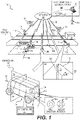
- FIG. 1 is a diagram depicting an implementation of a fleet of autonomous vehicles that are communicatively networked to an autonomous vehicle service platform, according to some embodiments.
- Diagram 100 depicts a fleet of autonomous vehicles 109 (e.g., one or more of autonomous vehicles 109a to 109e) operating as a service, each autonomous vehicle 109 being configured to self-drive a road network 110 and establish a communication link 192 with an autonomous vehicle service platform 101.
- a user 102 may transmit a request 103 for autonomous transportation via one or more networks 106 to autonomous vehicle service platform 101.
- autonomous vehicle service platform 101 may dispatch one of autonomous vehicles 109 to transport user 102 autonomously from geographic location 119 to geographic location 111.
- Autonomous vehicle service platform 101 may dispatch an autonomous vehicle from a station 190 to geographic location 119, or may divert an autonomous vehicle 109c, already in transit (e.g., without occupants), to service the transportation request for user 102. Autonomous vehicle service platform 101 may be further configured to divert an autonomous vehicle 109c in transit, with passengers, responsive to a request from user 102 (e.g., as a passenger). In addition, autonomous vehicle service platform 101 may be configured to reserve an autonomous vehicle 109c in transit, with passengers, for diverting to service a request of user 102 subsequent to dropping off existing passengers. Note that multiple autonomous vehicle service platforms 101 (not shown) and one or more stations 190 may be implemented to service one or more autonomous vehicles 109 in connection with road network 110. One or more stations 190 may be configured to store, service, manage, and/or maintain an inventory of autonomous vehicles 109 (e.g., station 190 may include one or more computing devices implementing autonomous vehicle service platform 101).
- bidirectional autonomous vehicle 130 may be configured to travel in either direction principally along, but not limited to, a longitudinal axis 131. Accordingly, bidirectional autonomous vehicle 130 may be configured to implement active lighting external to the vehicle to alert others (e.g., other drivers, pedestrians, cyclists, etc.) in the adjacent vicinity, and a direction in which bidirectional autonomous vehicle 130 is traveling.
- active sources of light 136 may be implemented as active lights 138a when traveling in a first direction, or may be implemented as active lights 138b when traveling in a second direction.
- Active lights 138a may be implemented using a first subset of one or more colors, with optional animation (e.g., light patterns of variable intensities of light or color that may change over time).
- active lights 138b may be implemented using a second subset of one or more colors and light patterns that may be different than those of active lights 138a.
- active lights 138a may be implemented using white-colored lights as "headlights”
- active lights 138b may be implemented using red-colored lights as "taillights.”
- Active lights 138a and 138b, or portions thereof, may be configured to provide other light-related functionalities, such as provide "turn signal indication" functions (e.g., using yellow light).
- logic in autonomous vehicle 130 may be configured to adapt active lights 138a and 138b to comply with various safety requirements and traffic regulations or laws for any number of jurisdictions.
- bidirectional autonomous vehicle 130 may be configured to have similar structural elements and components in each quad portion, such as quad portion 194.
- the quad portions are depicted, at least in this example, as portions of bidirectional autonomous vehicle 130 defined by the intersection of a plane 132 and a plane 134, both of which pass through the vehicle to form two similar halves on each side of planes 132 and 134.
- bidirectional autonomous vehicle 130 may include an autonomous vehicle controller 147 that includes logic (e.g., hardware or software, or as combination thereof) that is configured to control a predominate number of vehicle functions, including driving control (e.g., propulsion, steering, etc.) and active sources 136 of light, among other functions.
- Bidirectional autonomous vehicle 130 also includes a number of sensors 139 disposed at various locations on the vehicle (other sensors are not shown).
- Autonomous vehicle controller 147 may be further configured to determine a local pose (e.g., local position) of an autonomous vehicle 109 and to detect external objects relative to the vehicle. For example, consider that bidirectional autonomous vehicle 130 is traveling in the direction 119 in road network 110. A localizer (not shown) of autonomous vehicle controller 147 can determine a local pose at the geographic location 111. As such, the localizer may use acquired sensor data, such as sensor data associated with surfaces of buildings 115 and 117, which can be compared against reference data, such as map data (e.g., 3D map data, including reflectance data) to determine a local pose.
- map data e.g., 3D map data, including reflectance data
- a perception engine (not shown) of autonomous vehicle controller 147 may be configured to detect, classify, and predict the behavior of external objects, such as external object 112 (a "tree") and external object 114 (a "pedestrian”). Classification of such external objects may broadly classify objects as static objects, such as external object 112, and dynamic objects, such as external object 114.
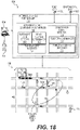
- autonomous vehicle service platform 101 is configured to provide teleoperator services should an autonomous vehicle 109 request teleoperation. For example, consider that an autonomous vehicle controller 147 in autonomous vehicle 109d detects an object 126 obscuring a path 124 on roadway 122 at point 191, as depicted in inset 120. If autonomous vehicle controller 147 cannot ascertain a path or trajectory over which vehicle 109d may safely transit with a relatively high degree of certainty, then autonomous vehicle controller 147 may transmit request message 105 for teleoperation services. In response, a teleoperator computing device 104 may receive instructions from a teleoperator 108 to perform a course of action to successfully (and safely) negotiate obstacles 126.
- Response data 107 then can be transmitted back to autonomous vehicle 109d to cause the vehicle to, for example, safely cross a set of double lines as it transits along the alternate path 121.
- teleoperator computing device 104 may generate a response identifying geographic areas to exclude from planning a path.
- a teleoperator 108 may define areas or locations that the autonomous vehicle must avoid.
- autonomous vehicle 130 and/or autonomous vehicle controller 147 can perform real-time (or near real-time) trajectory calculations through autonomous-related operations, such as localization and perception, to enable autonomous vehicles 109 to self-drive.
- bidirectional nature of bidirectional autonomous vehicle 130 provides for a vehicle that has quad portions 194 (or any other number of symmetric portions) that are similar or are substantially similar to each other. Such symmetry reduces complexity of design and decreases relatively the number of unique components or structures, thereby reducing inventory and manufacturing complexities.
- a drivetrain and wheel system may be disposed in any of the quad portions 194.
- autonomous vehicle controller 147 is configured to invoke teleoperation services to reduce the likelihood that an autonomous vehicle 109 is delayed in transit while resolving an event or issue that may otherwise affect the safety of the occupants.
- the visible portion of road network 110 depicts a geo-fenced region that may limit or otherwise control the movement of autonomous vehicles 109 to the road network shown in FIG.1 .
- autonomous vehicle 109 and a fleet thereof, may be configurable to operate as a level 4 ("full self-driving automation," or L4) vehicle that can provide transportation on demand with the convenience and privacy of point-to-point personal mobility while providing the efficiency of shared vehicles.
- L4 level 4
- autonomous vehicle 109, or any autonomous vehicle described herein may be configured to omit a steering wheel or any other mechanical means of providing manual (i.e., human-controlled) steering for autonomous vehicle 109.
- autonomous vehicle 109, or any autonomous vehicle described herein may be configured to omit a seat or location reserved within the vehicle for an occupant to engage a steering wheel or any mechanical interface for a steering system.
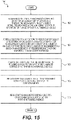
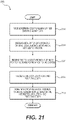
- FIG. 2 is an example of a flow diagram to monitor a fleet of autonomous vehicles, according to some embodiments.
- flow 200 begins when a fleet of autonomous vehicles are monitored.
- At least one autonomous vehicle includes an autonomous vehicle controller configured to cause the vehicle to autonomously transit from a first geographic region to a second geographic region.
- data representing an event associated with a calculated confidence level for a vehicle is detected.
- An event may be a condition or situation affecting operation, or potentially affecting operation, of an autonomous vehicle.
- the events may be internal to an autonomous vehicle, or external. For example, an obstacle obscuring a roadway may be viewed as an event, as well as a reduction or loss of communication.
- An event may include traffic conditions or congestion, as well as unexpected or unusual numbers or types of external objects (or tracks) that are perceived by a perception engine.
- An event may include weather-related conditions (e.g., loss of friction due to ice or rain) or the angle at which the sun is shining (e.g., at sunset), such as low angle to the horizon that cause sun to shine brightly in the eyes of human drivers of other vehicles. These and other conditions may be viewed as events that cause invocation of the teleoperator service or for the vehicle to execute a safe-stop trajectory.
- data representing a subset of candidate trajectories may be received from an autonomous vehicle responsive to the detection of the event.
- a planner of an autonomous vehicle controller may calculate and evaluate large numbers of trajectories (e.g., thousands or greater) per unit time, such as a second.
- candidate trajectories are a subset of the trajectories that provide for relatively higher confidence levels that an autonomous vehicle may move forward safely in view of the event (e.g., using an alternate path provided by a teleoperator). Note that some candidate trajectories may be ranked or associated with higher degrees of confidence than other candidate trajectories.
- subsets of candidate trajectories may originate from any number of sources, such as a planner, a teleoperator computing device (e.g., teleoperators can determine and provide approximate paths), etc., and may be combined as a superset of candidate trajectories.
- path guidance data may be identified at one or more processors. The path guidance data may be configured to assist a teleoperator in selecting a guided trajectory from one or more of the candidate trajectories. In some instances, the path guidance data specifies a value indicative of a confidence level or probability that indicates the degree of certainty that a particular candidate trajectory may reduce or negate the probability that the event may impact operation of an autonomous vehicle.
- a guided trajectory, as a selected candidate trajectory, may be received at 210, responsive to input from a teleoperator (e.g., a teleoperator may select at least one candidate trajectory as a guided trajectory from a group of differently-ranked candidate trajectories). The selection may be made via an operator interface that lists a number of candidate trajectories, for example, in order from highest confidence levels to lowest confidence levels.
- the selection of a candidate trajectory as a guided trajectory may be transmitted to the vehicle, which, in turn, implements the guided trajectory for resolving the condition by causing the vehicle to perform a teleoperator-specified maneuver.
- the autonomous vehicle may transition from a non-normative operational state.
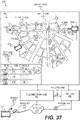
- FIG. 3A is a diagram depicting examples of sensors and other autonomous vehicle components, according to some examples.
- Diagram 300 depicts an interior view of a bidirectional autonomous vehicle 330 that includes sensors, signal routers 345, drive trains 349, removable batteries 343, audio generators 344 (e.g., speakers or transducers), and autonomous vehicle (“AV”) control logic 347.
- AV autonomous vehicle
- Sensors shown in diagram 300 include image capture sensors 340 (e.g., light capture devices or cameras of any type), audio capture sensors 342 (e.g., microphones of any type), radar devices 348, sonar devices 341 (or other like sensors, including ultrasonic sensors or acoustic-related sensors), and LIDAR devices 346, among other sensor types and modalities (some of which are not shown, such inertial measurement units, or "IMUs," global positioning system (“GPS”) sensors, sonar sensors, etc.).
- quad portion 350 is representative of the symmetry of each of four "quad portions" of bidirectional autonomous vehicle 330 (e.g., each quad portion 350 may include a wheel, a drivetrain 349, similar steering mechanisms, similar structural support and members, etc.
- autonomous vehicle controller 347a is depicted as being used in a bidirectional autonomous vehicle 330, autonomous vehicle controller 347a is not so limited and may be implemented in unidirectional autonomous vehicles or any other type of vehicle, whether on land, in air, or at sea. Note that the depicted and described positions, locations, orientations, quantities, and types of sensors shown in FIG. 3A are not intended to be limiting, and, as such, there may be any number and type of sensor, and any sensor may be located and oriented anywhere on autonomous vehicle 330.
- portions of the autonomous vehicle (“AV") control logic 347 may be implemented using clusters of graphics processing units (“GPUs”) implementing a framework and programming model suitable for programming the clusters of GPUs.
- GPUs graphics processing units
- CUDA compute unified device architecture
- API application programming interface
- CUDA TM is produced and maintained by NVIDIA of Santa Clara, California. Note that other programming languages may be implemented, such as OpenCL, or any other parallel programming language.
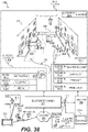
- autonomous vehicle control logic 347 may be implemented in hardware and/or software as autonomous vehicle controller 347a, which is shown to include a motion controller 362, a planner 364, a perception engine 366, and a localizer 368.
- autonomous vehicle controller 347a is configured to receive camera data 340a, LIDAR data 346a, and radar data 348a, or any other range-sensing or localization data, including sonar data 341a or the like.
- Autonomous vehicle controller 347a is also configured to receive positioning data, such as GPS data 352, IMU data 354, and other position-sensing data (e.g., wheel-related data, such as steering angles, angular velocity, etc.).
- autonomous vehicle controller 347a may receive any other sensor data 356, as well as reference data 339.
- reference data 339 includes map data (e.g., 3D map data, 2D map data, 4D map data (e.g., including Epoch Determination)) and route data (e.g., road network data, including, but not limited to, RNDF data (or similar data), MDF data (or similar data), etc.
- Localizer 368 is configured to receive sensor data from one or more sources, such as GPS data 352, wheel data, IMU data 354, LIDAR data 346a, camera data 340a, radar data 348a, and the like, as well as reference data 339 (e.g., 3D map data and route data). Localizer 368 integrates (e.g., fuses the sensor data) and analyzes the data by comparing sensor data to map data to determine a local pose (or position) of bidirectional autonomous vehicle 330. According to some examples, localizer 368 may generate or update the pose or position of any autonomous vehicle in real-time or near real-time. Note that localizer 368 and its functionality need not be limited to "bi-directional" vehicles and can be implemented in any vehicle of any type.
- localizer 368 (as well as other components of AV controller 347a) may be implemented in a "uni-directional" vehicle or any non-autonomous vehicle.
- data describing a local pose may include one or more of an x-coordinate, a y-coordinate, a z-coordinate (or any coordinate of any coordinate system, including polar or cylindrical coordinate systems, or the like), a yaw value, a roll value, a pitch value (e.g., an angle value), a rate (e.g., velocity), altitude, and the like.
- Perception engine 366 is configured to receive sensor data from one or more sources, such as LIDAR data 346a, camera data 340a, radar data 348a, and the like, as well as local pose data. Perception engine 366 may be configured to determine locations of external objects based on sensor data and other data. External objects, for instance, may be objects that are not part of a drivable surface. For example, perception engine 366 may be able to detect and classify external objects as pedestrians, bicyclists, dogs, other vehicles, etc. (e.g., perception engine 366 is configured to classify the objects in accordance with a type of classification, which may be associated with semantic information, including a label).
- sources such as LIDAR data 346a, camera data 340a, radar data 348a, and the like
- Perception engine 366 may be configured to determine locations of external objects based on sensor data and other data. External objects, for instance, may be objects that are not part of a drivable surface. For example, perception engine 366 may be
- the external objects may be labeled as dynamic objects or static objects.
- an external object classified as a tree may be labeled as a static object
- an external object classified as a pedestrian may be labeled as a static object.
- External objects labeled as static mayor may not be described in map data. Examples of external objects likely to be labeled as static include traffic cones, cement barriers arranged across a roadway, lane closure signs, newly-placed mailboxes or trash cans adjacent a roadway, etc. Examples of external objects likely to be labeled as dynamic include bicyclists, pedestrians, animals, other vehicles, etc.
- the external object is labeled as dynamic, and further data about the external object may indicate a typical level of activity and velocity, as well as behavior patterns associated with the classification type. Further data about the external object may be generated by tracking the external object.
- the classification type can be used to predict or otherwise determine the likelihood that an external object may, for example, interfere with an autonomous vehicle traveling along a planned path.
- an external object that is classified as a pedestrian may be associated with some maximum speed, as well as an average speed (e.g., based on tracking data).
- the velocity of the pedestrian relative to the velocity of an autonomous vehicle can be used to determine if a collision is likely.
- perception engine 364 may determine a level of uncertainty associated with a current and future state of objects. In some examples, the level of uncertainty may be expressed as an estimated value (or probability).
- Planner 364 is configured to receive perception data from perception engine 366, and may also include localizer data from localizer 368.
- the perception data may include an obstacle map specifying static and dynamic objects located in the vicinity of an autonomous vehicle, whereas the localizer data may include a local pose or position.
- planner 364 generates numerous trajectories, and evaluates the trajectories, based on at least the location of the autonomous vehicle against relative locations of external dynamic and static objects.
- Planner 364 selects an optimal trajectory based on a variety of criteria over which to direct the autonomous vehicle in way that provides for collision-free travel.
- planner 364 may be configured to calculate the trajectories as probabilistically-determined trajectories.
- planner 364 may transmit steering and propulsion commands (as well as decelerating or braking commands) to motion controller 362.
- Motion controller 362 subsequently may convert any of the commands, such as a steering command, a throttle or propulsion command, and a braking command, into control signals (e.g., for application to actuators or other mechanical interfaces) to implement changes in steering or wheel angles 351 and/or velocity 353.
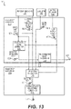
- FIGs. 3B to 3E are diagrams depicting examples of sensor field redundancy and autonomous vehicle adaption to a loss of a sensor field, according to some examples.
- Diagram 391 of FIG. 3B depicts a sensor field 301a in which sensor 310a detects objects (e.g., for determining range or distance, or other information). While sensor 310a may implement any type of sensor or sensor modality, sensor 310a and similarly-described sensors, such as sensors 310b, 310c, and 310d, may include LIDAR devices. Therefore, sensor fields 301a, 301b, 301c, and 301d each includes a field into which lasers extend.
- 3C depicts four overlapping sensor fields each of which is generated by a corresponding LIDAR sensor 310 (not shown). As shown, portions 301 of the sensor fields include no overlapping sensor fields (e.g., a single LIDAR field), portions 302 of the sensor fields include two overlapping sensor fields, and portions 303 include three overlapping sensor fields, whereby such sensors provide for multiple levels of redundancy should a LIDAR sensor fail.
- FIG. 3D depicts a loss of a sensor field due to failed operation of LIDAR 309, according to some examples.
- Sensor field 302 of FIG. 3C is transformed into a single sensor field 305, one of sensor fields 301 of FIG. 3C is lost to a gap 304, and three of sensor fields 303 of FIG. 3C are transformed into sensor fields 306 (i.e., limited to two overlapping fields).
- an autonomous vehicle controller (not shown) is configured to leverage the bidirectional nature of autonomous vehicle 330c to address the loss of sensor field at the leading area in front of the vehicle.
- 3E depicts a bidirectional maneuver for restoring a certain robustness of the sensor field in front of autonomous vehicle 330d.
- a more robust sensor field 302 is disposed at the rear of the vehicle 330d coextensive with taillights 348.
- autonomous vehicle 330d performs a bidirectional maneuver by pulling into a driveway 397 and switches its directionality such that taillights 348 actively switch to the other side (e.g., the trailing edge) of autonomous vehicle 330d.
- autonomous vehicle 330d restores a robust sensor field 302 in front of the vehicle as it travels along direction of travel 398.
- the above-described bidirectional maneuver obviates a requirement for a more complicated maneuver that requires backing up into a busy roadway.
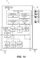
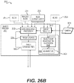
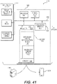
- FIG. 4 is a functional block diagram depicting a system including an autonomous vehicle service platform that is communicatively coupled via a communication layer to an autonomous vehicle controller, according to some examples.
- Diagram 400 depicts an autonomous vehicle controller ("AV") 447 disposed in an autonomous vehicle 430, which, in turn, includes a number of sensors 470 coupled to autonomous vehicle controller 447.
- AV autonomous vehicle controller
- Sensors 470 include one or more LIDAR devices 472, one or more cameras 474, one or more radars 476, one or more global positioning system (“GPS") data receiver-sensors, one or more inertial measurement units (“IMUs”) 475, one or more odometry sensors 477 (e.g., wheel encoder sensors, wheel speed sensors, and the like), and any other suitable sensors 478, such as infrared cameras or sensors, hyperspectral-capable sensors, ultrasonic sensors (or any other acoustic energy-based sensor), radio frequency-based sensors, etc.
- wheel angle sensors configured to sense steering angles of wheels may be included as odometry sensors 477 or suitable sensors 478.
- autonomous vehicle controller 447 may include four or more LIDARs 472, sixteen or more cameras 474 and four or more radar units 476. Further, sensors 470 may be configured to provide sensor data to components of autonomous vehicle controller 447 and to elements of autonomous vehicle service platform 401. As shown in diagram 400, autonomous vehicle controller 447 includes a planner 464, a motion controller 462, a localizer 468, a perception engine 466, and a local map generator 440. Note that elements depicted in diagram 400 of FIG. 4 may include structures and/or functions as similarly-named elements described in connection to one or more other drawings.
- Localizer 468 is configured to localize autonomous vehicle (i.e., determine a local pose) relative to reference data, which may include map data, route data (e.g., road network data, such as RNDF-like data), and the like. In some cases, localizer 468 is configured to identity, for example, a point in space that may represent a location of autonomous vehicle 430 relative to features of a representation of an environment. Localizer 468 is shown to include a sensor data integrator 469, which may be configured to integrate multiple subsets of sensor data (e.g., of different sensor modalities) to reduce uncertainties related to each individual type of sensor.
- sensor data integrator 469 may be configured to integrate multiple subsets of sensor data (e.g., of different sensor modalities) to reduce uncertainties related to each individual type of sensor.
- sensor data integrator 469 is configured to fuse sensor data (e.g., LIDAR data, camera data, radar data, etc.) to form integrated sensor data values for determining a local pose.
- localizer 468 retrieves reference data originating from a reference data repository 405, which includes a map data repository 405a for storing 2D map data, 3D map data, 4D map data, and the like.
- Localizer 468 may be configured to identify at least a subset of features in the environment to match against map data to identify, or otherwise confirm, a pose of autonomous vehicle 430.
- localizer 468 may be configured to identify any amount of features in an environment, such that a set of features can one or more features, or all features.
- any amount of LIDAR data may be compared against data representing a map for purposes of localization.
- non-matched objects resulting from the comparison of the environment features and map data may be a dynamic object, such as a vehicle, bicyclist, pedestrian, etc.
- detection of dynamic objects, including obstacles may be performed with or without map data.
- dynamic objects may be detected and tracked independently of map data (i.e., in the absence of map data).
- 2D map data and 3D map data may be viewed as "global map data" or map data that has been validated at a point in time by autonomous vehicle service platform 401.
- map data in map data repository 405a may be updated and/or validated periodically, a deviation may exist between the map data and an actual environment in which the autonomous vehicle is positioned. Therefore, localizer 468 may retrieve locally-derived map data generated by local map generator 440 to enhance localization.
- Local map generator 440 is configured to generate local map data in real-time or near real-time.
- local map generator 440 may receive static and dynamic object map data to enhance the accuracy of locally generated maps by, for example, disregarding dynamic objects in localization.
- local map generator 440 may be integrated with, or formed as part of, localizer 468.
- local map generator 440 may be configured to generate map and/or reference data based on simultaneous localization and mapping ("SLAM") or the like.
- SLAM simultaneous localization and mapping
- localizer 468 may implement a "hybrid" approach to using map data, whereby logic in localizer 468 may be configured to select various amounts of map data from either map data repository 405a or local map data from local map generator 440, depending on the degrees of reliability of each source of map data. Therefore, localizer 468 may still use out-of-date map data in view of locally-generated map data.
- Perception engine 466 is configured to, for example, assist planner 464 in planning routes and generating trajectories by identifying objects of interest in a surrounding environment in which autonomous vehicle 430 is transiting. Further, probabilities may be associated with each of the object of interest, whereby a probability may represent a likelihood that an object of interest may be a threat to safe travel (e.g., a fast-moving motorcycle may require enhanced tracking rather than a person sitting at a bus stop bench while reading a newspaper). As shown, perception engine 466 includes an object detector 442 and an object classifier 444.
- Object detector 442 is configured to distinguish objects relative to other features in the environment, and object classifier 444 may be configured to classify objects as either dynamic or static objects and track the locations of the dynamic and the static objects relative to autonomous vehicle 430 for planning purposes. Further, perception engine 466 may be configured to assign an identifier to a static or dynamic object that specifies whether the object is (or has the potential to become) an obstacle that may impact path planning at planner 464. Although not shown in FIG. 4 , note that perception engine 466 may also perform other perception-related functions, such as segmentation and tracking, examples of which are described below.
- Planner 464 is configured to generate a number of candidate trajectories for accomplishing a goal to reaching a destination via a number of paths or routes that are available.
- Trajectory evaluator 465 is configured to evaluate candidate trajectories and identify which subsets of candidate trajectories are associated with higher degrees of confidence levels of providing collision-free paths to the destination. As such, trajectory evaluator 465 can select an optimal trajectory based on relevant criteria for causing commands to generate control signals for vehicle components 450 (e.g., actuators or other mechanisms). Note that the relevant criteria may include any number of factors that define optimal trajectories, the selection of which need not be limited to reducing collisions.
- the selection of trajectories may be made to optimize user experience (e.g., user comfort) as well as collision-free trajectories that comply with traffic regulations and laws.
- User experience may be optimized by moderating accelerations in various linear and angular directions (e.g., to reduce jerking-like travel or other unpleasant motion).
- at least a portion of the relevant criteria can specify which of the other criteria to override or supersede, while maintain optimized, collision-free travel.
- legal restrictions may be temporarily lifted or deemphasized when generating trajectories in limited situations (e.g., crossing double yellow lines to go around a cyclist or travelling at higher speeds than the posted speed limit to match traffic flows).
- control signals are configured to cause propulsion and directional changes at the drivetrain and/or wheels.
- motion controller 462 is configured to transform commands into control signals (e.g., velocity, wheel angles, etc.) for controlling the mobility of autonomous vehicle 430.
- control signals e.g., velocity, wheel angles, etc.
- planner 464 can generate a request to teleoperator 404 for teleoperator support.
- Autonomous vehicle service platform 401 includes teleoperator 404 (e.g., a teleoperator computing device), reference data repository 405, a map updater 406, a vehicle data controller 408, a calibrator 409, and an off-line object classifier 410. Note that each element of autonomous vehicle service platform 401 may be independently located or distributed and in communication with other elements in autonomous vehicle service platform 401. Further, element of autonomous vehicle service platform 401 may independently communicate with the autonomous vehicle 430 via the communication layer 402.
- Map updater 406 is configured to receive map data (e.g., from local map generator 440, sensors 460, or any other component of autonomous vehicle controller 447), and is further configured to detect deviations, for example, of map data in map data repository 405a from a locally-generated map.
- Vehicle data controller 408 can cause map updater 406 to update reference data within repository 405 and facilitate updates to 2D, 3D, and/or 4D map data.
- vehicle data controller 408 can control the rate at which local map data is received into autonomous vehicle service platform 408 as well as the frequency at which map updater 406 performs updating of the map data.
- Calibrator 409 is configured to perform calibration of various sensors of the same or different types. Calibrator 409 may be configured to determine the relative poses of the sensors (e.g., in Cartesian space (x, y, z)) and orientations of the sensors (e.g., roll, pitch and yaw). The pose and orientation of a sensor, such a camera, LIDAR sensor, radar sensor, etc., may be calibrated relative to other sensors, as well as globally relative to the vehicle's reference frame. Off-line self-calibration can also calibrate or estimate other parameters, such as vehicle inertial tensor, wheel base, wheel radius or surface road friction. Calibration can also be done online to detect parameter change, according to some examples.
- calibration by calibrator 409 may include intrinsic parameters of the sensors (e.g., optical distortion, beam angles, etc.) and extrinsic parameters. In some cases, calibrator 409 may be performed by maximizing a correlation between depth discontinuities in 3D laser data and edges of image data, as an example.
- Off-line object classification 410 is configured to receive data, such as sensor data, from sensors 470 or any other component of autonomous vehicle controller 447.
- an off-line classification pipeline of off-line object classification 410 may be configured to pre-collect and annotate objects (e.g., manually by a human and/or automatically using an offline labeling algorithm), and may further be configured to train an online classifier (e.g., object classifier 444), which can provide real-time classification of object types during online autonomous operation.
- an online classifier e.g., object classifier 444.
- FIG. 5 is an example of a flow diagram to control an autonomous vehicle, according to some embodiments.
- flow 500 begins when sensor data originating from sensors of multiple modalities at an autonomous vehicle is received, for example, by an autonomous vehicle controller.
- One or more subsets of sensor data may be integrated for generating fused data to improve, for example, estimates.
- a sensor stream of one or more sensors e.g., of same or different modalities
- subsets of LIDAR sensor data and camera sensor data may be fused at 504 to facilitate localization.
- data representing objects based on the least two subsets of sensor data may be derived at a processor.
- data identifying static objects or dynamic objects may be derived (e.g., at a perception engine) from at least LIDAR and camera data.
- a detected obj ect is determined to affect a planned path, and a subset of trajectories are evaluated (e.g., at a planner) responsive to the detected object at 510.
- a confidence level is determined at 512 to exceed a range of acceptable confidence levels associated with normative operation of an autonomous vehicle.
- a confidence level may be such that a certainty of selecting an optimized path is less likely, whereby an optimized path may be determined as a function of the probability of facilitating collision-free travel, complying with traffic laws, providing a comfortable user experience (e.g., comfortable ride), and/or generating candidate trajectories on any other factor.
- a request for an alternate path may be transmitted to a teleoperator computing device at 514. Thereafter, the teleoperator computing device may provide a planner with an optimal trajectory over which an autonomous vehicle made travel.
- the vehicle may also determine that executing a safe-stop maneuver is the best course of action (e.g., safely and automatically causing an autonomous vehicle to a stop at a location of relatively low probabilities of danger).
- a safe-stop maneuver is the best course of action (e.g., safely and automatically causing an autonomous vehicle to a stop at a location of relatively low probabilities of danger).
- FIG. 6 is a diagram depicting an example of an architecture for an autonomous vehicle controller, according to some embodiments.
- Diagram 600 depicts a number of processes including a motion controller process 662, a planner processor 664, a perception process 666, a mapping process 640, and a localization process 668, some of which may generate or receive data relative to other processes.
- Other processes such as such as processes 670 and 650 may facilitate interactions with one or more mechanical components of an autonomous vehicle.
- perception process 666, mapping process 640, and localization process 668 are configured to receive sensor data from sensors 670
- planner process 664 and perception process 666 are configured to receive guidance data 606, which may include route data, such as road network data.
- localization process 668 is configured to receive map data 605a (i.e., 2D map data), map data 605b (i.e., 3D map data), and local map data 642, among other types of map data.
- localization process 668 may also receive other forms of map data, such as 4D map data, which may include, for example, an epoch determination.
- Localization process 668 is configured to generate local position data 641 representing a local pose. Local position data 641 is provided to motion controller process 662, planner process 664, and perception process 666.
- Perception process 666 is configured to generate static and dynamic object map data 667, which, in turn, may be transmitted to planner process 664.
- static and dynamic object map data 667 may be transmitted with other data, such as semantic classification information and predicted object behavior.
- Planner process 664 is configured to generate trajectories data 665, which describes a number of trajectories generated by planner 664.
- Motion controller process uses trajectories data 665 to generate low-level commands or control signals for application to actuators 650 to cause changes in steering angles and/or velocity.
- FIG. 7 is a diagram depicting an example of an autonomous vehicle service platform implementing redundant communication channels to maintain reliable communications with a fleet of autonomous vehicles, according to some embodiments.
- Diagram 700 depicts an autonomous vehicle service platform 701 including a reference data generator 705, a vehicle data controller 702, an autonomous vehicle fleet manager 703, a teleoperator manager 707, a simulator 740, and a policy manager 742.
- Reference data generator 705 is configured to generate and modify map data and route data (e.g., RNDF data). Further, reference data generator 705 may be configured to access 2D maps in 2D map data repository 720, access 3D maps in 3D map data repository 722, and access route data in route data repository 724.
- map data and route data e.g., RNDF data
- Vehicle data controller 702 may be configured to perform a variety of operations. For example, vehicle data controller 702 may be configured to change a rate that data is exchanged between a fleet of autonomous vehicles and platform 701 based on quality levels of communication over channels 770. During bandwidth-constrained periods, for example, data communications may be prioritized such that teleoperation requests from autonomous vehicle 730 are prioritized highly to ensure delivery. Further, variable levels of data abstraction may be transmitted per vehicle over channels 770, depending on bandwidth available for a particular channel.
- Autonomous vehicle fleet manager 703 is configured to coordinate the dispatching of autonomous vehicles 730 to optimize multiple variables, including an efficient use of battery power, times of travel, whether or not an air-conditioning unit in an autonomous vehicle 730 may be used during low charge states of a battery, etc., any or all of which may be monitored in view of optimizing cost functions associated with operating an autonomous vehicle service.
- An algorithm may be implemented to analyze a variety of variables with which to minimize costs or times of travel for a fleet of autonomous vehicles. Further, autonomous vehicle fleet manager 703 maintains an inventory of autonomous vehicles as well as parts for accommodating a service schedule in view of maximizing up-time of the fleet.
- Teleoperator manager 707 is configured to manage a number of teleoperator computing devices 704 with which teleoperators 708 provide input.
- Simulator 740 is configured to simulate operation of one or more autonomous vehicles 730, as well as the interactions between teleoperator manager 707 and an autonomous vehicle 730.
- Simulator 740 may also simulate operation of a number of sensors (including the introduction of simulated noise) disposed in autonomous vehicle 730.
- an environment such as a city, may be simulated such that a simulated autonomous vehicle can be introduced to the synthetic environment, whereby simulated sensors may receive simulated sensor data, such as simulated laser returns.
- Simulator 740 may provide other functions as well, including validating software updates and/or map data.
- Policy manager 742 is configured to maintain data representing policies or rules by which an autonomous vehicle ought to behave in view of a variety of conditions or events that an autonomous vehicle encounters while traveling in a network of roadways. In some cases, updated policies and/or rules may be simulated in simulator 740 to confirm safe operation of a fleet of autonomous vehicles in view of changes to a policy.
- Communication channels 770 are configured to provide networked communication links among a fleet of autonomous vehicles 730 and autonomous vehicle service platform 701.
- communication channel 770 includes a number of different types of networks 771, 772, 773, and 774, with corresponding subnetworks (e.g., 771a to 771n), to ensure a certain level of redundancy for operating an autonomous vehicle service reliably.
- the different types of networks in communication channels 770 may include different cellular network providers, different types of data networks, etc., to ensure sufficient bandwidth in the event of reduced or lost communications due to outages in one or more networks 771, 772, 773, and 774.
- FIG. 8 is a diagram depicting an example of a messaging application configured to exchange data among various applications, according to some embodiments.
- Diagram 800 depicts an teleoperator application 801 disposed in a teleoperator manager, and an autonomous vehicle application 830 disposed in an autonomous vehicle, whereby teleoperator applications 801 and autonomous vehicle application 830 exchange message data via a protocol that facilitates communications over a variety of networks, such as network 871, 872, and other networks 873.
- the communication protocol is a middleware protocol implemented as a Data Distribution Service TM having a specification maintained by the Object Management Group consortium.
- teleoperator application 801 and autonomous vehicle application 830 may include a message router 854 disposed in a message domain, the message router being configured to interface with the teleoperator API 852.
- message router 854 is a routing service.
- message domain 850a in teleoperator application 801 may be identified by a teleoperator identifier, whereas message domain 850b be may be identified as a domain associated with a vehicle identifier.
- Teleoperator API 852 in teleoperator application 801 is configured to interface with teleoperator processes 803a to 803c, whereby teleoperator process 803b is associated with an autonomous vehicle identifier 804, and teleoperator process 803c is associated with an event identifier 806 (e.g., an identifier that specifies an intersection that may be problematic for collision-free path planning).
- Teleoperator API 852 in autonomous vehicle application 830 is configured to interface with an autonomous vehicle operating system 840, which includes sensing application 842, a perception application 844, a localization application 846, and a control application 848.
- the above-described communications protocol may facilitate data exchanges to facilitate teleoperations as described herein.
- the above-described communications protocol may be adapted to provide secure data exchanges among one or more autonomous vehicles and one or more autonomous vehicle service platforms.
- message routers 854 may be configured to encrypt and decrypt messages to provide for secured interactions between, for example, a teleoperator process 803 and an autonomous vehicle operation system 840.
- FIG. 9 is a diagram depicting types of data for facilitating teleoperations using a communications protocol described in FIG. 8 , according to some examples.
- Diagram 900 depicts a teleoperator 908 interfacing with a teleoperator computing device 904 coupled to a teleoperator application 901, which is configured to exchange data via a data-centric messaging bus 972 implemented in one or more networks 971.
- Data-centric messaging bus 972 provides a communication link between teleoperator application 901 and autonomous vehicle application 930.
- Teleoperator API 962 of teleoperator application 901 is configured to receive message service configuration data 964 and route data 960, such as road network data (e.g., RNDF-like data), mission data (e.g., MDF-data), and the like.
- a messaging service bridge 932 is also configured to receive messaging service configuration data 934.
- Messaging service configuration data 934 and 964 provide configuration data to configure the messaging service between teleoperator application 901 and autonomous vehicle application 930.
- An example of messaging service configuration data 934 and 964 includes quality of service (“QoS") configuration data implemented to configure a Data Distribution Service TM application.
- QoS quality of service
- obstacle data 920 is generated by a perception system of an autonomous vehicle controller.
- planner options data 924 is generated by a planner to notify a teleoperator of a subset of candidate trajectories
- position data 926 is generated by the localizer.
- Obstacle data 920, planner options data 924, and position data 926 are transmitted to a messaging service bridge 932, which, in accordance with message service configuration data 934, generates telemetry data 940 and query data 942, both of which are transmitted via data-centric messaging bus 972 into teleoperator application 901 as telemetry data 950 and query data 952.
- Teleoperator API 962 receives telemetry data 950 and inquiry data 952, which, in turn are processed in view of Route data 960 and message service configuration data 964.
- the resultant data is subsequently presented to a teleoperator 908 via teleoperator computing device 904 and/or a collaborative display (e.g., a dashboard display visible to a group of collaborating teleoperators 908).
- Teleoperator 908 reviews the candidate trajectory options that are presented on the display of teleoperator computing device 904, and selects a guided trajectory, which generates command data 982 and query response data 980, both of which are passed through teleoperator API 962 as query response data 954 and command data 956.
- query response data 954 and command data 956 are transmitted via data-centric messaging bus 972 into autonomous vehicle application 930 as query response data 944 and command data 946.
- Messaging service bridge 932 receives query response data 944 and command data 946 and generates teleoperator command data 928, which is configured to generate a teleoperator-selected trajectory for implementation by a planner. Note that the above-described messaging processes are not intended to be limiting, and other messaging protocols may be implemented as well.
- FIG. 10 is a diagram illustrating an example of a teleoperator interface with which a teleoperator may influence path planning, according to some embodiments.
- Diagram 1000 depicts examples of an autonomous vehicle 1030 in communication with an autonomous vehicle service platform 1001, which includes a teleoperator manager 1007 configured to facilitate teleoperations.
- teleoperator manager 1007 receives data that requires teleoperator 1008 to preemptively view a path of an autonomous vehicle approaching a potential obstacle or an area of low planner confidence levels so that teleoperator 1008 may be able to address an issue in advance.
- an intersection that an autonomous vehicle is approaching may be tagged as being problematic.
- user interface 1010 displays a representation 1014 of a corresponding autonomous vehicle 1030 transiting along a path 1012, which has been predicted by a number of trajectories generated by a planner. Also displayed are other vehicles 1011 and dynamic objects 1013, such as pedestrians, that may cause sufficient confusion at the planner, thereby requiring teleoperation support. User interface 1010 also presents to teleoperator 1008 a current velocity 1022, a speed limit 1024, and an amount of charge 1026 presently in the batteries. According to some examples, user interface 1010 may display other data, such as sensor data as acquired from autonomous vehicle 1030.
- planner 1064 has generated a number of trajectories that are coextensive with a planner-generated path 1044 regardless of a detected unidentified object 1046.
- Planner 1064 may also generate a subset of candidate trajectories 1040, but in this example, the planner is unable to proceed given present confidence levels. If planner 1064 fails to determine an alternative path, a teleoperation request may be transmitted. In this case, a teleoperator may select one of candidate trajectories 1040 to facilitate travel by autonomous vehicle 1030 that is consistent with teleoperator-based path 1042.
- FIG. 11 is a diagram depicting an example of a planner configured to invoke teleoperations, according to some examples.
- Diagram 1100 depicts a planner 1164 including a topography manager 1110, a route manager 1112, a path generator 1114, a trajectory evaluator 1120, and a trajectory tracker 1128.
- Topography manager 1110 is configured to receive map data, such as 3D map data or other like map data that specifies topographic features.
- Topography manager 1110 is further configured to identify candidate paths based on topographic-related features on a path to a destination.
- topography manager 1110 receives 3D maps generated by sensors associated with one or more autonomous vehicles in the fleet.
- Route manager 1112 is configured to receive environmental data 1103, which may include traffic-related information associated with one or more routes that may be selected as a path to the destination.
- Path generator 1114 receives data from topography manager 1110 and route manager 1112, and generates one or more paths or path segments suitable to direct autonomous vehicle toward a destination. Data representing one or more paths or path segments is transmitted into trajectory evaluator 1120.
- Trajectory evaluator 1120 includes a state and event manager 1122, which, in turn, may include a confidence level generator 1123. Trajectory evaluator 1120 further includes a guided trajectory generator 1126 and a trajectory generator 1124. Further, planner 1164 is configured to receive policy data 1130, perception engine data 1132, and localizer data 1134.
- Policy data 1130 may include criteria with which planner 1164 uses to determine a path that has a sufficient confidence level with which to generate trajectories, according to some examples.
- Examples of policy data 1130 include policies that specify that trajectory generation is bounded by stand-off distances to external objects (e.g., maintaining a safety buffer of 3 feet from a cyclist, as possible), or policies that require that trajectories must not cross a center double yellow line, or policies that require trajectories to be limited to a single lane in a 4-lane roadway (e.g., based on past events, such as typically congregating at a lane closest to a bus stop), and any other similar criteria specified by policies.
- Perception engine data 1132 includes maps of locations of static objects and dynamic objects of interest, and localizer data 1134 includes at least a local pose or position.
- State and event manager 1122 may be configured to probabilistically determine a state of operation for an autonomous vehicle. For example, a first state of operation (i.e., "normative operation”) may describe a situation in which trajectories are collision-free, whereas a second state of operation (i.e., "non-normative operation”) may describe another situation in which the confidence level associated with possible trajectories are insufficient to guarantee collision-free travel. According to some examples, state and event manager 1122 is configured to use perception data 1132 to determine a state of autonomous vehicle that is either normative or non-normative. Confidence level generator 1123 may be configured to analyze perception data 1132 to determine a state for the autonomous vehicle.
- confidence level generator 1123 may use semantic information associated with static and dynamic objects, as well as associated probabilistic estimations, to enhance a degree of certainty that planner 1164 is determining safe course of action.
- planner 1164 may use perception engine data 1132 that specifies a probability that an object is either a person or not a person to determine whether planner 1164 is operating safely (e.g., planner 1164 may receive a degree of certainty that an object has a 98% probability of being a person, and a probability of 2% that the object is not a person).
- a relatively low confidence level may trigger planner 1164 to transmit a request 1135 for teleoperation support to autonomous vehicle service platform 1101.
- telemetry data and a set of candidate trajectories may accompany the request. Examples of telemetry data include sensor data, localization data, perception data, and the like.
- a teleoperator 1108 may transmit via teleoperator computing device 1104 a selected trajectory 1137 to guided trajectory generator 1126. As such, selected trajectory 1137 is a trajectory formed with guidance from a teleoperator.
- guided trajectory generator 1126 Upon confirming there is no change in the state (e.g., a non-normative state is pending), guided trajectory generator 1126 passes data to trajectory generator 1124, which, in turn, causes trajectory tracker 1128, as a trajectory tracking controller, to use the teleop-specified trajectory for generating control signals 1170 (e.g., steering angles, velocity, etc.).
- control signals 1170 e.g., steering angles, velocity, etc.
- planner 1164 may trigger transmission of a request 1135 for teleoperation support prior to a state transitioning to a non-normative state.
- an autonomous vehicle controller and/or its components can predict that a distant obstacle may be problematic and preemptively cause planner 1164 to invoke teleoperations prior to the autonomous vehicle reaching the obstacle.
- the autonomous vehicle may cause a delay by transitioning to a safe state upon encountering the obstacle or scenario (e.g., pulling over and off the roadway).
- teleoperations may be automatically invoked prior to an autonomous vehicle approaching a particular location that is known to be difficult to navigate. This determination may optionally take into consideration other factors, including the time of day, the position of the sun, if such situation is likely to cause a disturbance to the reliability of sensor readings, and traffic or accident data derived from a variety of sources.
- FIG. 12 is an example of a flow diagram configured to control an autonomous vehicle, according to some embodiments.
- flow 1200 begins.
- perception engine data may include metadata associated with objects, whereby the metadata specifies a degree of certainty associated with a specific classification type. For instance, a dynamic object may be classified as a "young pedestrian" with an 85% confidence level of being correct.
- localizer data may be received (e.g., at a planner).
- the localizer data may include map data that is generated locally within the autonomous vehicle.
- the local map data may specify a degree of certainty (including a degree of uncertainty) that an event at a geographic region may occur.
- An event may be a condition or situation affecting operation, or potentially affecting operation, of an autonomous vehicle.
- the events may be internal (e.g., failed or impaired sensor) to an autonomous vehicle, or external (e.g., roadway obstruction). Examples of events are described herein, such as in FIG. 2 as well as in other figures and passages.
- a path coextensive with the geographic region of interest may be determined at 1206. For example, consider that the event is the positioning of the sun in the sky at a time of day in which the intensity of sunlight impairs the vision of drivers during rush hour traffic. As such, it is expected or predicted that traffic may slow down responsive to the bright sunlight.
- a planner may preemptively invoke teleoperations if an alternate path to avoid the event is less likely.
- a local position is determined at a planner based on local pose data.
- a state of operation of an autonomous vehicle may be determined (e.g., probabilistically), for example, based on a degree of certainty for a classification type and a degree of certainty of the event, which is may be based on any number of factors, such as speed, position, and other state information.
- a young pedestrian is detected by the autonomous vehicle during the event in which other drivers' vision likely will be impaired by the sun, thereby causing an unsafe situation for the young pedestrian.
- a relatively unsafe situation can be detected as a probabilistic event that may be likely to occur (i.e., an unsafe situation for which teleoperations may be invoked).
- a likelihood that the state of operation is in a normative state is determined, and based on the determination, a message is transmitted to a teleoperator computing device requesting teleoperations to preempt a transition to a next state of operation (e.g., preempt transition from a normative to non-normative state of operation, such as an unsafe state of operation).
- FIG. 13 depicts an example in which a planner may generate a trajectory, according to some examples.
- Diagram 1300 includes a trajectory evaluator 1320 and a trajectory generator 1324.
- Trajectory evaluator 1320 includes a confidence level generator 1322 and a teleoperator query messenger 1329.
- trajectory evaluator 1320 is coupled to a perception engine 1366 to receive static map data 1301, and current and predicted object state data 1303.
- Trajectory evaluator 1320 also receives local pose data 1305 from localizer 1368 and plan data 1307 from a global planner 1369.
- confidence level generator 1322 receives static map data 1301 and current and predicted object state data 1303.
- confidence level generator 1322 may determine that detected trajectories are associated with unacceptable confidence level values. As such, confidence level generator 1322 transmits detected trajectory data 1309 (e.g., data including candidate trajectories) to notify a teleoperator via teleoperator query messenger 1329, which, in turn, transmits a request 1370 for teleoperator assistance.
- detected trajectory data 1309 e.g., data including candidate trajectories
- trajectory calculator 1325 In another state of operation (e.g., a normative state), static map data 1301, current and predicted object state data 1303, local pose data 1305, and plan data 1307 (e.g., global plan data) are received into trajectory calculator 1325, which is configured to calculate (e.g., iteratively) trajectories to determine an optimal one or more paths. Next, at least one path is selected and is transmitted as selected path data 1311. According to some embodiments, trajectory calculator 1325 is configured to implement re-planning of trajectories as an example.
- Nominal driving trajectory generator 1327 is configured to generate trajectories in a refined approach, such as by generating trajectories based on receding horizon control techniques. Nominal driving trajectory generator 1327 subsequently may transmit nominal driving trajectory path data 1372 to, for example, a trajectory tracker or a vehicle controller to implement physical changes in steering, acceleration, and other components.
- FIG. 14 is a diagram depicting another example of an autonomous vehicle service platform, according to some embodiments.
- Diagram 1400 depicts an autonomous vehicle service platform 1401 including a teleoperator manager 1407 that is configured to manage interactions and/or communications among teleoperators 1408, teleoperator computing devices 1404, and other components of autonomous vehicle service platform 1401.
- autonomous vehicle service platform 1401 includes a simulator 1440, a repository 1441, a policy manager 1442, a reference data updater 1438, a 2D map data repository 1420, a 3D map data repository 1422, and a route data repository 1424.
- Other map data such as 4D map data (e.g., using epoch determination), may be implemented and stored in a repository (not shown).
- Teleoperator action recommendation controller 1412 includes logic configured to receive and/or control a teleoperation service request via autonomous vehicle (“AV") planner data 1472, which can include requests for teleoperator assistance as well as telemetry data and other data.
- planner data 1472 may include recommended candidate trajectories or paths from which a teleoperator 1408 via teleoperator computing device 1404 may select.
- teleoperator action recommendation controller 1412 may be configured to access other sources of recommended candidate trajectories from which to select an optimum trajectory.
- candidate trajectories contained in autonomous vehicle planner data 1472 may, in parallel, be introduced into simulator 1440, which is configured to simulate an event or condition being experienced by an autonomous vehicle requesting teleoperator assistance.
- Simulator 1440 can access map data and other data necessary for performing a simulation on the set of candidate trajectories, whereby simulator 1440 need not exhaustively reiterate simulations to confirm sufficiency. Rather, simulator 1440 may provide either confirm the appropriateness of the candidate trajectories, or may otherwise alert a teleoperator to be cautious in their selection.
- Teleoperator interaction capture analyzer 1416 may be configured to capture numerous amounts of teleoperator transactions or interactions for storage in repository 1441, which, for example, may accumulate data relating to a number of teleoperator transactions for analysis and generation of policies, at least in some cases.
- repository 1441 may also be configured to store policy data for access by policy manager 1442.
- teleoperator interaction capture analyzer 1416 may apply machine learning techniques to empirically determine how best to respond to events or conditions causing requests for teleoperation assistance.
- policy manager 1442 may be configured to update a particular policy or generate a new policy responsive to analyzing the large set of teleoperator interactions (e.g., subsequent to applying machine learning techniques).
- Policy manager 1442 manages policies that may be viewed as rules or guidelines with which an autonomous vehicle controller and its components operate under to comply with autonomous operations of a vehicle. In some cases, a modified or updated policy may be applied to simulator 1440 to confirm the efficacy of permanently releasing or implementing such policy changes.
- Simulator interface controller 1414 is configured to provide an interface between simulator 1440 and teleoperator computing devices 1404. For example, consider that sensor data from a fleet of autonomous vehicles is applied to reference data updater 1438 via autonomous (“AV") fleet data 1470, whereby reference data updater 1438 is configured to generate updated map and route data 1439.
- updated map and route data 1439 may be preliminarily released as an update to data in map data repositories 1420 and 1422, or as an update to data in route data repository 1424.
- such data may be tagged as being a "beta version" in which a lower threshold for requesting teleoperator service may be implemented when, for example, a map tile including preliminarily updated information is used by an autonomous vehicle.
- updated map and route data 1439 may be introduced to simulator 1440 for validating the updated map data.
- the previously lowered threshold for requesting a teleoperator service related to map tiles is canceled.
- User interface graphics controller 1410 provides rich graphics to teleoperators 1408, whereby a fleet of autonomous vehicles may be simulated within simulator 1440 and may be accessed via teleoperator computing device 1404 as if the simulated fleet of autonomous vehicles were real.
- FIG. 15 is an example of a flow diagram to control an autonomous vehicle, according to some embodiments.
- flow 1500 begins.
- Message data may be received at a teleoperator computing device for managing a fleet of autonomous vehicles.
- the message data may indicate event attributes associated with a non-normative state of operation in the context of a planned path for an autonomous vehicle.
- an event may be characterized as a particular intersection that becomes problematic due to, for example, a large number of pedestrians, hurriedly crossing the street against a traffic light.
- the event attributes describe the characteristics of the event, such as, for example, the number of people crossing the street, the traffic delays resulting from an increased number of pedestrians, etc.
- a teleoperation repository may be accessed to retrieve a first subset of recommendations based on simulated operations of aggregated data associated with a group of autonomous vehicles.
- a simulator may be a source of recommendations with which a teleoperator may implement.
- the teleoperation repository may also be accessed to retrieve a second subset of recommendations based on an aggregation of teleoperator interactions responsive to similar event attributes.
- a teleoperator interaction capture analyzer may apply machine learning techniques to empirically determine how best to respond to events having similar attributes based on previous requests for teleoperation assistance.
- the first subset and the second subset of recommendations are combined to form a set of recommended courses of action for the autonomous vehicle.
- representations of the set of recommended courses of actions may be presented visually on a display of a teleoperator computing device.
- data signals representing a selection (e.g., by teleoperator) of a recommended course of action may be detected.
- FIG. 16 is a diagram of an example of an autonomous vehicle fleet manager implementing a fleet optimization manager, according to some examples.
- Diagram 1600 depicts an autonomous vehicle fleet manager that is configured to manage a fleet of autonomous vehicles 1630 transiting within a road network 1650.
- Autonomous vehicle fleet manager 1603 is coupled to a teleoperator 1608 via a teleoperator computing device 1604, and is also coupled to a fleet management data repository 1646.
- Autonomous vehicle fleet manager 1603 is configured to receive policy data 1602 and environmental data 1606, as well as other data.
- fleet optimization manager 1620 is shown to include a transit request processor 1631, which, in turn, includes a fleet data extractor 1632 and an autonomous vehicle dispatch optimization calculator 1634.
- Transit request processor 1631 is configured to process transit requests, such as from a user 1688 who is requesting autonomous vehicle service.
- Fleet data extractor 1632 is configured to extract data relating to autonomous vehicles in the fleet. Data associated with each autonomous vehicle is stored in repository 1646. For example, data for each vehicle may describe maintenance issues, scheduled service calls, daily usage, battery charge and discharge rates, and any other data, which may be updated in real-time, may be used for purposes of optimizing a fleet of autonomous vehicles to minimize downtime.
- Autonomous vehicle dispatch optimization calculator 1634 is configured to analyze the extracted data and calculate optimized usage of the fleet so as to ensure that the next vehicle dispatched, such as from station 1652, provides for the least travel times and/or costs-in the aggregate-for the autonomous vehicle service.
- Fleet optimization manager 1620 is shown to include a hybrid autonomous vehicle/non-autonomous vehicle processor 1640, which, in turn, includes an AV/non-AV optimization calculator 1642 and a non-AV selector 1644.
- hybrid autonomous vehicle/non-autonomous vehicle processor 1640 is configured to manage a hybrid fleet of autonomous vehicles and human-driven vehicles (e.g., as independent contractors).
- autonomous vehicle service may employ non-autonomous vehicles to meet excess demand, or in areas, such as non-AV service region 1690, that may be beyond a geo-fence or in areas of poor communication coverage.
- Non-AV selector 1644 includes logic for selecting a number of non-AV drivers to assist based on calculations derived by AV/non-AV optimization calculator 1642.
- FIG. 17 is an example of a flow diagram to manage a fleet of autonomous vehicles, according to some embodiments.
- flow 1700 begins.
- policy data is received.
- the policy data may include parameters that define how best apply to select an autonomous vehicle for servicing a transit request.
- fleet management data from a repository may be extracted.
- the fleet management data includes subsets of data for a pool of autonomous vehicles (e.g., the data describes the readiness of vehicles to service a transportation request).
- data representing a transit request is received. For exemplary purposes, the transit request could be for transportation from a first geographic location to a second geographic location.
- attributes based on the policy data are calculated to determine a subset of autonomous vehicles that are available to service the request.
- attributes may include a battery charge level and time until next scheduled maintenance.
- an autonomous vehicle is selected as transportation from the first geographic location to the second geographic location, and data is generated to dispatch the autonomous vehicle to a third geographic location associated with the origination of the transit request.
- FIG. 18 is a diagram illustrating an autonomous vehicle fleet manager implementing an autonomous vehicle communications link manager, according to some embodiments.
- Diagram 1800 depicts an autonomous vehicle fleet manager that is configured to manage a fleet of autonomous vehicles 1830 transiting within a road network 1850 that coincides with a communication outage at an area identified as "reduced communication region" 1880.
- Autonomous vehicle fleet manager 1803 is coupled to a teleoperator 1808 via a teleoperator computing device 1804.
- Autonomous vehicle fleet manager 1803 is configured to receive policy data 1802 and environmental data 1806, as well as other data.
- an autonomous vehicle communications link manager 1820 is shown to include an environment event detector 1831, a policy adaption determinator 1832, and a transit request processor 1834.
- Environment event detector 1831 is configured to receive environmental data 1806 specifying a change within the environment in which autonomous vehicle service is implemented. For example, environmental data 1806 may specify that region 1880 has degraded communication services, which may affect the autonomous vehicle service. Policy adaption determinator 1832 may specify parameters with which to apply when receiving transit requests during such an event (e.g., during a loss of communications).
- Transit request processor 1834 is configured to process transit requests in view of the degraded communications. In this example, a user 1888 is requesting autonomous vehicle service. Further, transit request processor 1834 includes logic to apply an adapted policy for modifying the way autonomous vehicles are dispatched so to avoid complications due to poor communications.
- Communication event detector 1840 includes a policy download manager 1842 and communications-configured ("COMM-configured") AV dispatcher 1844.
- Policy download manager 1842 is configured to provide autonomous vehicles 1830 an updated policy in view of reduced communications region 1880, whereby the updated policy may specify routes to quickly exit region 1880 if an autonomous vehicle enters that region.
- autonomous vehicle 1864 may receive an updated policy moments before driving into region 1880.
- autonomous vehicle 1864 implements the updated policy and selects route 1866 to drive out of region 1880 quickly.
- COMM-configured AV dispatcher 1844 may be configured to identify points 1865 at which to park autonomous vehicles that are configured as relays to establishing a peer-to-peer network over region 1880.
- COMM-configured AV dispatcher 1844 is configured to dispatch autonomous vehicles 1862 (without passengers) to park at locations 1865 for the purposes of operating as communication towers in a peer-to-peer ad hoc network.
- FIG. 19 is an example of a flow diagram to determine actions for autonomous vehicles during an event, such as degraded or lost communications, according to some embodiments.
- flow 1900 begins. Policy data is received, whereby the policy data defines parameters with which to apply to transit requests in a geographical region during an event.
- one or more of the following actions may be implemented: (1) dispatch a subset of autonomous vehicles to geographic locations in the portion of the geographic location, the subset of autonomous vehicles being configured to either park at specific geographic locations and each serve as a static communication relay, or transit in a geographic region to each serve as a mobile communication relay, (2) implement peer-to-peer communications among a portion of the pool of autonomous vehicles associated with the portion of the geographic region, (3) provide to the autonomous vehicles an event policy that describes a route to egress the portion of the geographic region during an event, (4) invoke teleoperations, and (5) recalculate paths so as to avoid the geographic portion. Subsequent to implementing the action, the fleet of autonomous vehicles is monitored at 1914.
- FIG. 20 is a diagram depicting an example of a localizer, according to some embodiments.
- Diagram 2000 includes a localizer 2068 configured to receive sensor data from sensors 2070, such as LIDAR data 2072, camera data 2074, radar data 2076, and other data 2078. Further, localizer 2068 is configured to receive reference data 2020, such as 2D map data 2022, 3D map data 2024, and 3D local map data. According to some examples, other map data, such as 4D map data 2025 and semantic map data (not shown), including corresponding data structures and repositories, may also be implemented. Further to diagram 2000, localizer 2068 includes a positioning system 2010 and a localization system 2012, both of which are configured to receive sensor data from sensors 2070 as well as reference data 2020. Localization data integrator 2014 is configured to receive data from positioning system 2010 and data from localization system 2012, whereby localization data integrator 2014 is configured to integrate or fuse sensor data from multiple sensors to form local pose data 2052.
- FIG. 21 is an example of a flow diagram to generate local pose data based on integrated sensor data, according to some embodiments.
- flow 2100 begins.
- reference data is received, the reference data including three dimensional map data.
- reference data such as 3D or 4D map data, may be received via one or more networks.
- localization data from one or more localization sensors is received and placed into a localization system.
- positioning data from one or more positioning sensors is received into a positioning system.
- the localization and positioning data are integrated.
- the localization data and positioning data are integrated to form local position data specifying a geographic position of an autonomous vehicle.
- FIG. 22 is a diagram depicting another example of a localizer, according to some embodiments.
- Diagram 2200 includes a localizer 2268, which, in turn, includes a localization system 2210 and a relative localization system 2212 to generate positioning-based data 2250 and local location-based data 2251, respectively.
- Localization system 2210 includes a projection processor 2254a for processing GPS data 2273, a GPS datum 2211, and 3D Map data 2222, among other optional data (e.g., 4D map data).
- Localization system 2210 also includes an odometry processor 2254b to process wheel data 2275 (e.g., wheel speed), vehicle model data 2213 and 3D map data 2222, among other optional data.
- localization system 2210 includes an integrator processor 2254c to process IMU data 2257, vehicle model data 2215, and 3D map data 2222, among other optional data.
- relative localization system 2212 includes a LIDAR localization processor 2254d for processing LIDAR data 2272, 2D tile map data 2220, 3D map data 2222, and 3D local map data 2223, among other optional data.
- Relative localization system 2212 also includes a visual registration processor 2254e to process camera data 2274, 3D map data 2222, and 3D local map data 2223, among other optional data.
- relative localization system 2212 includes a radar return processor 2254f to process radar data 2276, 3D map data 2222, and 3D local map data 2223, among other optional data.
- radar return processor 2254f to process radar data 2276, 3D map data 2222, and 3D local map data 2223, among other optional data.
- other types of sensor data and sensors or processors may be implemented, such as sonar data and the like.
- localization-based data 2250 and relative localization-based data 2251 may be fed into data integrator 2266a and localization data integrator 2266, respectively.
- Data integrator 2266a and localization data integrator 2266 may be configured to fuse corresponding data, whereby localization-based data 2250 may be fused at data integrator 2266a prior to being fused with relative localization-based data 2251 at localization data integrator 2266.
- data integrator 2266a is formed as part of localization data integrator 2266, or is absent. Regardless, a localization-based data 2250 and relative localization-based data 2251 can be both fed into localization data integrator 2266 for purposes of fusing data to generate local position data 2252.
- Localization-based data 2250 may include unary-constrained data (and uncertainty values) from projection processor 2254a, as well as binary-constrained data (and uncertainty values) from odometry processor 2254b and integrator processor 2254c.
- Relative localization-based data 2251 may include unary-constrained data (and uncertainty values) from localization processor 2254d and visual registration processor 2254e, and optionally from radar return processor 2254 f.
- localization data integrator 2266 may implement non-linear smoothing functionality, such as a Kalman filter (e.g., a gated Kalman filter), a relative bundle adjuster, pose-graph relaxation, particle filter, histogram filter, or the like.
- FIG. 23 is a diagram depicting an example of a perception engine, according to some embodiments.
- Diagram 2300 includes a perception engine 2366, which, in turn, includes a segmentation processor 2310, an object tracker 2330, and a classifier 2360. Further, perception engine 2366 is configured to receive a local position data 2352, LIDAR data 2372, camera data 2374, and radar data 2376, for example. Note that other sensor data, such as sonar data, may be accessed to provide functionalities of perception engine 2366.
- Segmentation processor 2310 is configured to extract ground plane data and/or to segment portions of an image to distinguish objects from each other and from static imagery (e.g., background). In some cases, 3D blobs may be segmented to distinguish each other.
- a blob may refer to a set of features that identify an object in a spatially-reproduced environment and may be composed of elements (e.g., pixels of camera data, points of laser return data, etc.) having similar characteristics, such as intensity and color.
- a blob may also refer to a point cloud (e.g., composed of colored laser return data) or other elements constituting an object.
- Object tracker 2330 is configured to perform frame-to-frame estimations of motion for blobs, or other segmented image portions. Further, data association is used to associate a blob at one location in a first frame at time, t1, to a blob in a different position in a second frame at time, t2.
- object tracker 2330 is configured to perform real-time probabilistic tracking of 3D objects, such as blobs.
- Classifier 2360 is configured to identify an object and to classify that object by classification type (e.g., as a pedestrian, cyclist, etc.) and by energy/activity (e.g. whether the object is dynamic or static), whereby data representing classification is described by a semantic label.
- probabilistic estimations of object categories may be performed, such as classifying an object as a vehicle, bicyclist, pedestrian, etc. with varying confidences per object class.
- Perception engine 2366 is configured to determine perception engine data 2354, which may include static object maps and/or dynamic object maps, as well as semantic information so that, for example, a planner may use this information to enhance path planning. According to various examples, one or more of segmentation processor 2310, object tracker 2330, and classifier 2360 may apply machine learning techniques to generate perception engine data 2354.
- FIG. 24 is an example of a flow chart to generate perception engine data, according to some embodiments.
- Flow chart 2400 begins at 2402, at which data representing a local position of an autonomous vehicle is retrieved.
- localization data from one or more localization sensors is received, and features of an environment in which the autonomous vehicle is disposed are segmented at 2406 to form segmented objects.
- One or more portions of the segmented object are tracked spatially at 2408 to form at least one tracked object having a motion (e.g., an estimated motion).
- a tracked object is classified at least as either being a static object or a dynamic object. In some cases, a static object or a dynamic object may be associated with a classification type.
- data identifying a classified object is generated. For example, the data identifying the classified object may include semantic information.
- FIG. 25 is an example of a segmentation processor, according to some embodiments.
- Diagram 2500 depicts a segmentation processor 2510 receiving LIDAR data from one or more LIDARs 2572 and camera image data from one or more cameras 2574.
- Local pose data 2552, LIDAR data, and camera image data are received into meta spin generator 2521.
- meta spin generator is configured to partition an image based on various attributes (e.g., color, intensity, etc.) into distinguishable regions (e.g., clusters or groups of a point cloud), at least two or more of which may be updated at the same time or about the same time.
- Meta spin data 2522 is used to perform object segmentation and ground segmentation at segmentation processor 2523, whereby both meta spin data 2522 and segmentation-related data from segmentation processor 2523 are applied to a scanned differencing processor 2513.
- Scanned differencing processor 2513 is configured to predict motion and/or relative velocity of segmented image portions, which can be used to identify dynamic objects at 2517. Data indicating objects with detected velocity at 2517 are optionally transmitted to the planner to enhance path planning decisions. Additionally, data from scanned differencing processor 2513 may be used to approximate locations of objects to form mapping of such objects (as well as optionally identifying a level of motion). In some examples, an occupancy grid map 2515 may be generated.
- Data representing an occupancy grid map 2515 may be transmitted to the planner to further enhance path planning decisions (e.g., by reducing uncertainties).
- image camera data from one or more cameras 2574 are used to classify blobs in blob classifier 2520, which also receives blob data 2524 from segmentation processor 2523.
- Segmentation processor 2510 also may receive raw radar returns data 2512 from one or more radars 2576 to perform segmentation at a radar segmentation processor 2514, which generates radar-related blob data 2516. Further to 10 FIG. 25 , segmentation processor 2510 may also receive and/or generate tracked blob data 2518 related to radar data.
- Blob data 2516, tracked blob data 2518, data from blob classifier 2520, and blob data 2524 may be used to track objects or portions thereof. According to some examples, one or more of the following may be optional: scanned differencing processor 2513, blob classification 2520, and data from radar 2576.
- FIG. 26A is a diagram depicting examples of an object tracker and a classifier, according to various embodiments.
- Object tracker 2630 of diagram 2600 is configured to receive blob data 2516, tracked blob data 2518, data from blob classifier 2520, blob data 2524, and camera image data from one or more cameras 2676.
- Image tracker 2633 is configured to receive camera image data from one or more cameras 2676 to generate tracked image data, which, in turn, may be provided to data association processor 2632.
- data association processor 2632 is configured to receive blob data 2516, tracked blob data 2518, data from blob classifier 2520, blob data 2524, and track image data from image tracker 2633, and is further configured to identify one or more associations among the above-described types of data.
- Data association processor 2632 is configured to track, for example, various blob data from one frame to a next frame to, for example, estimate motion, among other things.
- data generated by data association processor 2632 may be used by track updater 2634 to update one or more tracks, or tracked objects.
- track updater 2634 may implement a Kalman Filter, or the like, to form updated data for tracked objects, which may be stored online in track database (“DB”) 2636.
- DB track database
- Feedback data may be exchanged via path 2699 between data association processor 2632 and track database 2636.
- image tracker 2633 may be optional and may be excluded.
- Object tracker 2630 may also use other sensor data, such as radar or sonar, as well as any other types of sensor data, for example.
- FIG. 26B is a diagram depicting another example of an object tracker according to at least some examples.
- Diagram 2601 includes an obj ect tracker 2631 that may include structures and/or functions as similarly-named elements described in connection to one or more other drawings (e.g., FIG. 26A ).
- object tracker 2631 includes an optional registration portion 2699 that includes a processor 2696 configured to perform object scan registration and data fusion.
- Processor 2696 is further configured to store the resultant data in 3D object database 2698.
- diagram 2600 also includes classifier 2660, which may include a track classification engine 2662 for generating static obstacle data 2672 and dynamic obstacle data 2674, both of which may be transmitted to the planner for path planning purposes.
- track classification engine 2662 is configured to determine whether an obstacle is static or dynamic, as well as another classification type for the object (e.g., whether the object is a vehicle, pedestrian, tree, cyclist, dog, cat, paper bag, etc.).
- Static obstacle data 2672 may be formed as part of an obstacle map (e.g., a 2D occupancy map), and dynamic obstacle data 2674 may be formed to include bounding boxes with data indicative of velocity and classification type.
- Dynamic obstacle data 2674 at least in some cases, includes 2D dynamic obstacle map data.
- FIG. 27 is an example of front-end processor for a perception engine, according to some examples.
- Diagram 2700 includes a ground segmentation processor 2723a for performing ground segmentation, and an over segmentation processor 2723b for performing "over-segmentation," according to various examples.
- Processors 2723a and 2723b are configured to receive optionally colored LIDAR data 2775.
- Over segmentation processor 2723b generates data 2710 of a first blob type (e.g., a relatively small blob), which is provided to an aggregation classification and segmentation engine 2712 that generates data 2714 of a second blob type.
- Data 2714 is provided to data association processor 2732, which is configured to detect whether data 2714 resides in track database 2736.
- Track classification engine 2762 is coupled to track database 2736 to identify and update/modify tracks by, for example, adding, removing or modifying track-related data.
- FIG. 28 is a diagram depicting a simulator configured to simulate an autonomous vehicle in a synthetic environment, according to various embodiments.
- Diagram 2800 includes a simulator 2840 that is configured to generate a simulated environment 2803.
- simulator 2840 is configured to use reference data 2822 (e.g., 3D map data and/or other map or route data including RNDF data or similar road network data) to generate simulated geometries, such as simulated surfaces 2892a and 2892b, within simulated environment 2803.
- Simulated surfaces 2892a and 2892b may simulate walls or front sides of buildings adjacent a roadway.
- Simulator 2840 may also pre-generated or procedurally generated use dynamic object data 2825 to simulate dynamic agents in a synthetic environment.
- simulated dynamic object 2801 is representative of a simulated cyclist having a velocity.
- the simulated dynamic agents may optionally respond to other static and dynamic agents in the simulated environment, including the simulated autonomous vehicle.
- simulated object 2801 may slow down for other obstacles in simulated environment 2803 rather than follow a preset trajectory, thereby creating a more realistic simulation of actual dynamic environments that exist in the real world.
- Simulator 2840 may be configured to generate a simulated autonomous vehicle controller 2847, which includes synthetic adaptations of a perception engine 2866, a localizer 2868, a motion controller 2862, and a planner 2864, each of which may have functionalities described herein within simulated environment 2803. Simulator 2840 may also generate simulated interfaces ("I/F") 2849 to simulate the data exchanges with different sensors modalities and different sensor data formats. As such, simulated interface 2849 may simulate a software interface for packetized data from, for example, a simulated LIDAR sensor 2872. Further, simulator 2840 may also be configured to generate a simulated autonomous vehicle 2830 that implements simulated AV controller 2847.
- a simulated autonomous vehicle controller 2847 which includes synthetic adaptations of a perception engine 2866, a localizer 2868, a motion controller 2862, and a planner 2864, each of which may have functionalities described herein within simulated environment 2803. Simulator 2840 may also generate simulated interfaces ("I/F") 2849 to simulate the
- Simulated autonomous vehicle 2830 includes simulated LIDAR sensors 2872, simulated camera or image sensors 2874, and simulated radar sensors 2876.
- simulated LIDAR sensor 2872 may be configured to generate a simulated laser consistent with ray trace 2892, which causes generation of simulated sensor return 2891.
- simulator 2840 may simulate the addition of noise or other environmental effects on sensor data (e.g., added diffusion or reflections that affect simulated sensor return 2891, etc.). Further yet, simulator 2840 may be configured to simulate a variety of sensor defects, including sensor failure, sensor miscalibration, intermittent data outages, and the like.
- Simulator 2840 includes a physics processor 2850 for simulating the mechanical, static, dynamic, and kinematic aspects of an autonomous vehicle for use in simulating behavior of simulated autonomous vehicle 2830.
- physics processor 2850 includes a content mechanics module 2851 for simulating contact mechanics, a collision detection module 2852 for simulating the interaction between simulated bodies, and a multibody dynamics module 2854 to simulate the interaction between simulated mechanical interactions.
- Simulator 2840 also includes a simulator controller 2856 configured to control the simulation to adapt the functionalities of any synthetically-generated element of simulated environment 2803 to determine cause-effect relationship, among other things.
- Simulator 2840 includes a simulator evaluator 2858 to evaluate the performance synthetically-generated element of simulated environment 2803.
- simulator evaluator 2858 may analyze simulated vehicle commands 2880 (e.g., simulated steering angles and simulated velocities) to determine whether such commands are an appropriate response to the simulated activities within simulated environment 2803.
- simulator evaluator 2858 may evaluate interactions of a teleoperator 2808 with the simulated autonomous vehicle 2830 via teleoperator computing device 2804.
- Simulator evaluator 2858 may evaluate the effects of updated reference data 2827, including updated map tiles and route data, which may be added to guide the responses of simulated autonomous vehicle 2830. Simulator evaluator 2858 may also evaluate the responses of simulator AV controller 2847 when policy data 2829 is updated, deleted, or added.
- the above-description of simulator 2840 is not intended to be limiting. As such, simulator 2840 is configured to perform a variety of different simulations of an autonomous vehicle relative to a simulated environment, which include both static and dynamic features. For example, simulator 2840 may be used to validate changes in software versions to ensure reliability. Simulator 2840 may also be used to determine vehicle dynamics properties and for calibration purposes. Further, simulator 2840 may be used to explore the space of applicable controls and resulting trajectories so as to effect learning by self-simulation.
- FIG. 29 is an example of a flow chart to simulate various aspects of an autonomous vehicle, according to some embodiments.
- Flow chart 2900 begins at 2902, at which reference data including three dimensional map data is received into a simulator. Dynamic object data defining motion patterns for a classified object may be retrieved at 2904.
- a simulated environment is formed based on at least three dimensional ("3D") map data and the dynamic object data.
- the simulated environment may include one or more simulated surfaces.
- an autonomous vehicle is simulated that includes a simulated autonomous vehicle controller that forms part of a simulated environment.
- the autonomous vehicle controller may include a simulated perception engine and a simulated localizer configured to receive sensor data.
- simulated sensor data are generated based on data for at least one simulated sensor return, and simulated vehicle commands are generated at 2912 to cause motion (e.g., vectored propulsion) by a simulated autonomous vehicle in a synthetic environment.
- simulated vehicle commands are evaluated to determine whether the simulated autonomous vehicle behaved consistent with expected behaviors (e.g., consistent with a policy).
- FIG. 30 is an example of a flow chart to generate map data, according to some embodiments.
- Flow chart 3000 begins at 3002, at which trajectory data is retrieved.
- the trajectory data may include trajectories captured over a duration of time (e.g., as logged trajectories).
- at least localization data may be received.
- the localization data may be captured over a duration of time (e.g., as logged localization data).
- a camera or other image sensor may be implemented to generate a subset of the localization data.
- the retrieved localization data may include image data.
- subsets of localization data are aligned to identifying a global position (e.g., a global pose).
- three dimensional (“3D") map data is generated based on the global position, and at 3012, the three dimensional map data is available for implementation by, for example, a manual route data editor (e.g., including a manual road network data editor, such as an RNDF editor), an automated route data generator (e.g., including an automatic road network generator, including an automatic RNDF generator), a fleet of autonomous vehicles, a simulator, a teleoperator computing device, and any other component of an autonomous vehicle service.
- a manual route data editor e.g., including a manual road network data editor, such as an RNDF editor
- an automated route data generator e.g., including an automatic road network generator, including an automatic RNDF generator
- a fleet of autonomous vehicles e.g., a simulator, a teleoperator computing device, and any other component of an autonomous vehicle service.
- FIG. 31 is a diagram depicting an architecture of a mapping engine, according to some embodiments.
- Diagram 3100 includes a 3D mapping engine that is configured to receive trajectory log data 3140, LIDAR log data 3172, camera log data 3174, radar log data 3176, and other optional logged sensor data (not shown).
- Logic 3141 includes a loop-closure detector 3150 configured to detect whether sensor data indicates a nearby point in space has been previously visited, among other things.
- Logic 3141 also includes a registration controller 3152 for aligning map data, including 3D map data in some cases, relative to one or more registration points. Further, logic 3141 provides data 3142 representing states of loop closures for use by a global pose graph generator 3143, which is configured to generate pose graph data 3145.
- pose graph data 3145 may also be generated based on data from registration refinement module 3146.
- Logic 3144 includes a 3D mapper 3154 and a LIDAR self-calibration unit 3156. Further, logic 3144 receives sensor data and pose graph data 3145 to generate 3D map data 3120 (or other map data, such as 4D map data). In some examples, logic 3144 may implement a truncated sign distance function ("TSDF") to fuse sensor data and/or map data to form optimal three-dimensional maps. Further, logic 3144 is configured to include texture and reflectance properties.
- TSDF truncated sign distance function
- 3D map data 3120 may be released for usage by a manual route data editor 3160 (e.g., an editor to manipulate Route data or other types of route or reference data), an automated route data generator 3162 (e.g., logic to configured to generate route data or other types of road network or reference data), a fleet of autonomous vehicles 3164, a simulator 3166, a teleoperator computing device 3168, and any other component of an autonomous vehicle service.
- Mapping engine 3110 may capture semantic information from manual annotation or automatically-generated annotation as well as other sensors, such as sonar or instrumented environment (e.g., smart stop-lights).
- FIG. 32 is a diagram depicting an autonomous vehicle application, according to some examples.
- Diagram 3200 depicts a mobile computing device 3203 including an autonomous service application 3240 that is configured to contact an autonomous vehicle service platform 3201 to arrange transportation of user 3202 via an autonomous vehicle 3230.
- autonomous service application 3240 may include a transportation controller 3242, which may be a software application residing on a computing device (e.g., a mobile phone 3203, etc.).
- Transportation controller 3242 is configured to receive, schedule, select, or perform operations related to autonomous vehicles and/or autonomous vehicle fleets for which a user 3202 may arrange transportation from the user's location to a destination. For example, user 3202 may open up an application to request vehicle 3230.
- the application may display a map and user 3202 may drop a pin to indicate their destination within, for example, a geo-fenced region.
- the application may display a list of nearby pre-specified pick-up locations, or provide the user with a text entry field in which to type a destination either by address or by name.
- autonomous vehicle application 3240 may also include a user identification controller 3246 that may be configured to detect that user 3202 is in a geographic region, or vicinity, near autonomous vehicle 3230, as the vehicle approaches. In some situations, user 3202 may not readily perceive or identify autonomous vehicle 3230 as it approaches for use by user 3203 (e.g., due to various other vehicles, including trucks, cars, taxis, and other obstructions that are typical in city environments).
- a user identification controller 3246 may be configured to detect that user 3202 is in a geographic region, or vicinity, near autonomous vehicle 3230, as the vehicle approaches. In some situations, user 3202 may not readily perceive or identify autonomous vehicle 3230 as it approaches for use by user 3203 (e.g., due to various other vehicles, including trucks, cars, taxis, and other obstructions that are typical in city environments).
- autonomous vehicle 3230 may establish a wireless communication link 3262 (e.g., via a radio frequency ("RF") signal, such as WiFi or Bluetooth ® , including BLE, or the like) for communicating and/or determining a spatial location of user 3202 relative to autonomous vehicle 3230 (e.g., using relative direction of RF signal and signal strength).
- RF radio frequency
- autonomous vehicle 3230 may detect an approximate geographic location of user 3202 using, for example, GPS data or the like.
- a GPS receiver (not shown) of mobile computing device 3203 may be configured to provide GPS data to autonomous vehicle service application 3240.
- user identification controller 3246 may provide GPS data via link 3260 to autonomous vehicle service platform 3201, which, in turn, may provide that location to autonomous vehicle 3230 via link 3261.
- autonomous vehicle 3230 may determine a relative distance and/or direction of user 3202 by comparing the user's GPS data to the vehicle's GPS-derived location.
- Autonomous vehicle 3230 may also include additional logic to identify the presence of user 3202, such that logic configured to perform face detection algorithms to detect either user 3202 generally, or to specifically identify the identity (e.g., name, phone number, etc.) of user 3202 based on the user's unique facial characteristics. Further, autonomous vehicle 3230 may include logic to detect codes for identifying user 3202. Examples of such codes include specialized visual codes, such as QR codes, color codes, etc., specialized audio codes, such as voice activated or recognized codes, etc., and the like. In some cases, a code may be an encoded security key that may be transmitted digitally via link 3262 to autonomous vehicle 3230 to ensure secure ingress and/or egress.
- one or more of the above-identified techniques for identifying user 3202 may be used as a secured means to grant ingress and egress privileges to user 3202 so as to prevent others from entering autonomous vehicle 3230 (e.g., to ensure third party persons do not enter an unoccupied autonomous vehicle prior to arriving at user 3202).
- any other means for identifying user 3202 and providing secured ingress and egress may also be implemented in one or more of autonomous vehicle service application 3240, autonomous vehicle service platform 3201, and autonomous vehicle 3230.
- autonomous vehicle 3230 may be configured to notify or otherwise alert user 3202 to the presence of autonomous vehicle 3230 as it approaches user 3202.
- autonomous vehicle 3230 may activate one or more light-emitting devices 3280 (e.g., LEDs) in accordance with specific light patterns.
- light-emitting devices 3280 e.g., LEDs
- certain light patterns are created so that user 3202 may readily perceive that autonomous vehicle 3230 is reserved to service the transportation needs of user 3202.
- autonomous vehicle 3230 may generate light patterns 3290 that may be perceived by user 3202 as a "wink," or other animation of its exterior and interior lights in such a visual and temporal way.
- the patterns of light 3290 may be generated with or without patterns of sound to identify to user 3202 that this vehicle is the one that they booked.
- autonomous vehicle user controller 3244 may implement a software application that is configured to control various functions of an autonomous vehicle. Further, an application may be configured to redirect or reroute the autonomous vehicle during transit to its initial destination. Further, autonomous vehicle user controller 3244 may be configured to cause on-board logic to modify interior lighting of autonomous vehicle 3230 to effect, for example, mood lighting.
- Controller 3244 may also control a source of audio (e.g., an external source such as Spotify, or audio stored locally on the mobile computing device 3203), select a type of ride (e.g., modify desired acceleration and braking aggressiveness, modify active suspension parameters to select a set of "road-handling" characteristics to implement aggressive driving characteristics, including vibrations, or to select “soft-ride” qualities with vibrations dampened for comfort), and the like.
- a source of audio e.g., an external source such as Spotify, or audio stored locally on the mobile computing device 3203
- select a type of ride e.g., modify desired acceleration and braking aggressiveness, modify active suspension parameters to select a set of "road-handling" characteristics to implement aggressive driving characteristics, including vibrations, or to select “soft-ride” qualities with vibrations dampened for comfort
- mobile computing device 3203 may be configured to control HVAC functions as well, like ventilation and temperature.
- FIGs. 33 to 35 illustrate examples of various computing platforms configured to provide various functionalities to components of an autonomous vehicle service, according to various embodiments.
- computing platform 3300 may be used to implement computer programs, applications, methods, processes, algorithms, or other software to perform the above-described techniques.
- FIG. 33 Note that various structures and/or functionalities of FIG. 33 are applicable to FIGs. 34 and 35 , and, as such, some elements in those figures may be discussed in the context of FIG. 33 .
- computing platform 3300 can be disposed in any device, such as a computing device 3390a, which may be disposed in one or more computing devices in an autonomous vehicle service platform, an autonomous vehicle 3391, and/or mobile computing device 3390b.
- a computing device 3390a which may be disposed in one or more computing devices in an autonomous vehicle service platform, an autonomous vehicle 3391, and/or mobile computing device 3390b.
- Computing platform 3300 includes a bus 3302 or other communication mechanism for communicating information, which interconnects subsystems and devices, such as processor 3304, system memory 3306 (e.g., RAM, etc.), storage device 3308 (e.g., ROM, etc.), an in-memory cache (which may be implemented in RAM 3306 or other portions of computing platform 3300), a communication interface 3313 (e.g., an Ethernet or wireless controller, a Bluetooth controller, NFC logic, etc.) to facilitate communications via a port on communication link 3321 to communicate, for example, with a computing device, including mobile computing and/or communication devices with processors.
- system memory 3306 e.g., RAM, etc.
- storage device 3308 e.g., ROM, etc.
- an in-memory cache which may be implemented in RAM 3306 or other portions of computing platform 3300
- a communication interface 3313 e.g., an Ethernet or wireless controller, a Bluetooth controller, NFC logic, etc.
- Processor 3304 can be implemented with one or more graphics processing units (“GPUs”), with one or more central processing units (“CPUs”), such as those manufactured by Intel ® Corporation, or one or more virtual processors, as well as any combination of CPUs and virtual processors.
- GPUs graphics processing units
- CPUs central processing units
- Computing platform 3300 exchanges data representing inputs and outputs via input-and-output devices 3301, including, but not limited to, keyboards, mice, audio inputs (e.g., speech-to-text devices), user interfaces, displays, monitors, cursors, touch-sensitive displays, LCD or LED displays, and other I/O-related devices.
- computing platform 3300 performs specific operations by processor 3304 executing one or more sequences of one or more instructions stored in system memory 3306, and computing platform 3300 can be implemented in a client-server arrangement, peer-to-peer arrangement, or as any mobile computing device, including smart phones and the like.
- Such instructions or data may be read into system memory 3306 from another computer readable medium, such as storage device 3308.
- hardwired circuitry may be used in place of or in combination with software instructions for implementation. Instructions may be embedded in software or firmware.
- the term "computer readable medium” refers to any tangible medium that participates in providing instructions to processor 3304 for execution. Such a medium may take many forms, including but not limited to, nonvolatile media and volatile media.
- Non-volatile media includes, for example, optical or magnetic disks and the like.
- Volatile media includes dynamic memory, such as system memory 3306.
- Computer readable media includes, for example, floppy disk, flexible disk, hard disk, magnetic tape, any other magnetic medium, CDROM, any other optical medium, punch cards, paper tape, any other physical medium with patterns of holes, RAM, PROM, EPROM, FLASH-EPROM, any other memory chip or cartridge, or any other medium from which a computer can read. Instructions may further be transmitted or received using a transmission medium.
- the term "transmission medium” may include any tangible or intangible medium that is capable of storing, encoding or carrying instructions for execution by the machine, and includes digital or analog communications signals or other intangible medium to facilitate communication of such instructions.
- Transmission media includes coaxial cables, copper wire, and fiber optics, including wires that comprise bus 3302 for transmitting a computer data signal.
- execution of the sequences of instructions may be performed by computing platform 3300.
- computing platform 3300 can be coupled by communication link 3321 (e.g., a wired network, such as LAN, PSTN, or any wireless network, including WiFi of various standards and protocols, Bluetooth ® , NFC, Zig-Bee, etc.) to any other processor to perform the sequence of instructions in coordination with (or asynchronous to) one another.
- Communication link 3321 e.g., a wired network, such as LAN, PSTN, or any wireless network, including WiFi of various standards and protocols, Bluetooth ® , NFC, Zig-Bee, etc.
- program code e.g., application code
- Received program code may be executed by processor 3304 as it is received, and/or stored in memory 3306 or other non-volatile storage for later execution.
- system memory 3306 can include various modules that include executable instructions to implement functionalities described herein.
- System memory 3306 may include an operating system (“O/S”) 3332, as well as an application 3336 and/or logic module(s) 3359.
- system memory 3306 includes an autonomous vehicle (“AV") controller module 3350 and/or its components (e.g., a perception engine module, a localization module, a planner module, and/or a motion controller module), any of which, or one or more portions of which, can be configured to facilitate an autonomous vehicle service by implementing one or more functions described herein.
- AV autonomous vehicle
- system memory 3306 includes an autonomous vehicle service platform module 3450 and/or its components (e.g., a teleoperator manager, a simulator, etc.), any of which, or one or more portions of which, can be configured to facilitate managing an autonomous vehicle service by implementing one or more functions described herein.
- autonomous vehicle service platform module 3450 and/or its components (e.g., a teleoperator manager, a simulator, etc.), any of which, or one or more portions of which, can be configured to facilitate managing an autonomous vehicle service by implementing one or more functions described herein.
- system memory 3306 includes an autonomous vehicle (“AV”) module and/or its components for use, for example, in a mobile computing device.
- AV autonomous vehicle
- One or more portions of module 3550 can be configured to facilitate delivery of an autonomous vehicle service by implementing one or more functions described herein.
- the structures and/or functions of any of the above-described features can be implemented in software, hardware, firmware, circuitry, or a combination thereof.
- the structures and constituent elements above, as well as their functionality may be aggregated with one or more other structures or elements.
- the elements and their functionality may be subdivided into constituent sub-elements, if any.
- the above-described techniques may be implemented using various types of programming or formatting languages, frameworks, syntax, applications, protocols, objects, or techniques.
- module can refer, for example, to an algorithm or a portion thereof, and/or logic implemented in either hardware circuitry or software, or a combination thereof. These can be varied and are not limited to the examples or descriptions provided.
- module 3350 of FIG. 33 , module 3450 of FIG. 34 , and module 3550 of FIG. 35 , or one or more of their components, or any process or device described herein, can be in communication (e.g., wired or wirelessly) with a mobile device, such as a mobile phone or computing device, or can be disposed therein.
- a mobile device such as a mobile phone or computing device
- a mobile device in communication with one or more modules 3359 (module 3350 of FIG. 33 , module 3450 of FIG. 34 , and module 3550 of FIG. 35 ) or one or more of its components (or any process or device described herein), can provide at least some of the structures and/or functions of any of the features described herein.
- the structures and/or functions of any of the above-described features can be implemented in software, hardware, firmware, circuitry, or any combination thereof. Note that the structures and constituent elements above, as well as their functionality, may be aggregated or combined with one or more other structures or elements.
- the elements and their functionality may be subdivided into constituent sub-elements, if any.
- at least some of the above-described techniques may be implemented using various types of programming or formatting languages, frameworks, syntax, applications, protocols, objects, or techniques.
- at least one of the elements depicted in any of the figures can represent one or more algorithms.
- at least one of the elements can represent a portion of logic including a portion of hardware configured to provide constituent structures and/or functionalities.
- module 3350 of FIG. 33 , module 3450 of FIG. 34 , and module 3550 of FIG. 35 , or one or more of its components, or any process or device described herein, can be implemented in one or more computing devices (i.e., any mobile computing device, such as a wearable device, an audio device (such as headphones or a headset) or mobile phone, whether worn or carried) that include one or more processors configured to execute one or more algorithms in memory.
- processors configured to execute one or more algorithms in memory.
- processors configured to execute one or more algorithms in memory.
- at least some of the elements in the above-described figures can represent one or more algorithms.
- at least one of the elements can represent a portion of logic including a portion of hardware configured to provide constituent structures and/or functionalities. These can be varied and are not limited to the examples or descriptions provided.
- RTL register transfer language
- FPGAs field-programmable gate arrays
- ASICs application-specific integrated circuits
- multi-chip modules multi-chip modules, or any other type of integrated circuit.
- module 3350 of FIG. 33 can be implemented in one or more computing devices that include one or more circuits.
- at least one of the elements in the above-described figures can represent one or more components of hardware.
- at least one of the elements can represent a portion of logic including a portion of a circuit configured to provide constituent structures and/or functionalities.
- the term "circuit" can refer, for example, to any system including a number of components through which current flows to perform one or more functions, the components including discrete and complex components.
- discrete components include transistors, resistors, capacitors, inductors, diodes, and the like
- complex components include memory, processors, analog circuits, digital circuits, and the like, including field-programmable gate arrays ("FPGAs"), application-specific integrated circuits ("ASICs").
- FPGAs field-programmable gate arrays
- ASICs application-specific integrated circuits
- a circuit can include a system of electronic components and logic components (e.g., logic configured to execute instructions, such that a group of executable instructions of an algorithm, for example, and, thus, is a component of a circuit).
- the term “module” can refer, for example, to an algorithm or a portion thereof, and/or logic implemented in either hardware circuitry or software, or a combination thereof (i.e., a module can be implemented as a circuit).
- algorithms and/or the memory in which the algorithms are stored are “components” of a circuit.
- circuit can also refer, for example, to a system of components, including algorithms. These can be varied and are not limited to the examples or descriptions provided.
- FIG. 36 is a diagram depicting an example of a teleoperator manager configured to at least influence navigational control of an autonomous vehicle, according to some examples.
- Diagram 3600 depicts a teleoperator manager 3607 that generates data configured to guide generation of trajectories at an autonomous vehicle 3630, where the guidance provided by teleoperator manager 3607 assists in facilitating navigation of autonomous vehicle 3630.
- Teleoperator manager 3607 may include logic, such as hardware or software, or a combination thereof, and may be disposed in a teleoperator computing device 3604 with which teleoperators 3608 may interact.
- a teleoperator 3608 may monitor remotely, such as via a user interface or display of teleoperator computing device 3604, a number of functions of autonomous vehicle 3630. Moreover, a teleoperator may visually discern an event based on view by autonomous vehicle 3630 similar to an occupant (e.g., a high definition, 3D view in 360 degrees or less, both horizontally and vertically) of the physical environment (e.g., roadway, cityscape, etc.) in which autonomous vehicle 3630 travels. In particular, the view may be a visualization of the environment relative to, for example, a leading surface of the autonomous vehicle 3630 in the direction of travel. The teleoperator 3608 may provide guidance or assistance to autonomous vehicle 3630 and a fleet of autonomous vehicles 3630a to assist in navigation or resolving any other event or condition, whether occurring external or internal to autonomous vehicle 3630.
- an occupant e.g., a high definition, 3D view in 360 degrees or less, both horizontally and vertically
- the view may be a
- Teleoperator manager 3607 is configured to facilitate a connection, or session, via a communication channel over network 3606 between one of teleoperators 3608 and autonomous vehicle 3630 responsive to receiving a signal to invoke teleoperations received from autonomous vehicle 3630, from within an autonomous vehicle service platform (not shown) in which teleoperator manager 3607 is disposed, or from teleoperator computing device 3604.
- Examples of such signals include message data and are configured to provide information for purposes of monitoring autonomous vehicle 3630 by teleoperator 3608 (i.e., without requiring active teleoperator intervention).
- such signals may include a request for teleoperator 3608 to perform a task (e.g., provide guidance).
- teleoperator manager 3607 may provide data representing implicit guidance or explicit guidance.
- explicit guidance includes actions relating to specific routing paths (i.e., specific roadways or segments) that may be transmitted from teleoperator manager 3607 via network 3606 as instruction data 3617.
- examples of implicit guidance include instructions to avoid or bypass certain geographic regions (e.g., suggested subset of roadways to deemphasize or exclude from trajectory calculations so as to guide autonomous vehicle 3630 away from these regions), as well as instructions specifying regions through which travel is preferred (e.g., suggested subsets of roadways or segments to emphasize or include (e.g., as a preference) in trajectory calculations so as to guide autonomous vehicle 3630 toward these regions).
- any teleoperator 3608 may initiate communication or otherwise cause communication between teleoperator computing device 3604 and autonomous vehicle 3630.
- teleoperator manager 3607 may be invoked responsive to message data 3619, which may include a request for one type of many teleoperation services.
- the request for teleoperation service may include a request to negotiate difficult or unsafe roadway conditions and obstacles external to autonomous vehicle 3630.
- An open door on a parked car that may be impeding travel by autonomous vehicle 3630 may be views as such an obstacle.
- Message data 3619 may also include data representing an indication that, for example, observed lane markings are not located at expected positions in the physical environment.
- Message data 3619 may also include a request for teleoperator services if, for instance, autonomous vehicle controller 3647 experiences difficulties identifying or classifying one or more objects or obstacles that may affect planning and/or trajectory generation.
- Message data 3619 may also include a request to monitor the operation of autonomous vehicle 3630 or any component therein (e.g., sensor performance, drivetrain characteristics, battery charge levels, etc.).
- message data 3619 may include information or a request to address sensor-related events, such as a degraded or failed LIDAR sensor, radar sensor, or sonar sensor. Other examples include faulty temperature measurements, degraded tachometer sensing on a drive train, etc. An example of degraded LIDAR sensor may be due to intense sunlight or other light affecting range measurements.
- Message data 3619 may also include information or a request to address measurements derived from multiple sensors, such as kinematic-related data.
- any autonomous vehicle in fleet of autonomous vehicles 3630a may generate message data 3619a to establish teleoperation services with teleoperator manager 3607, or to provide autonomous vehicle 3630 teleoperation services.
- message data 3619 may include any type of data, such as telemetry data or planner data, that may be suitable for facilitating teleoperations.
- teleoperator manager 3607 may be configured invoke teleoperation services such that autonomous vehicle 3630 need not generate message data to establish a session between teleoperator computing device 3604 and autonomous vehicle 3630.
- teleoperator manager 3607 may include a message data generator 3690 that is configured to self-generate teleoperation service messages to establish communications between teleoperator computing device 3604 and autonomous vehicle 3630.
- Diagram 3600 further depicts teleoperator manager 3607 being communicatively coupled to a repository 3641 and to a reference data repository 3605, which is shown to include map data repository 3605a.
- Repository 3641 may be configured as a policy repository configured to store data representing policies or rules with which to determine when to invoke teleoperation services, based on a number of factors that may affect trajectory generation by autonomous vehicle controller 3647, at least in some examples.
- data stored in repository 3641 may include a rule to connect teleoperator computing device 3604 to autonomous vehicles 3630 if the vehicle remains stopped (e.g., beyond a time-related threshold) at a stop sign without any other detected obstacle or impediment that may be prohibiting travel through the stop sign.
- map data associated with a geographic region through which autonomous vehicle 3630 is predicted to travel is accessed by teleoperator manager 3607.
- map data may be linked to alert data ("AD") 3605b that indicates that one or more routes (e.g., in a map tile) may be associated with certain levels of uncertainty or navigational complexities.
- AD alert data
- alert data may be linked to temporary map data that is used temporarily for localization until, for example, the map data may be validated (e.g., via simulation, etc.). Therefore, alert data 3605b causes instantiation of a teleoperations session to enable a teleoperator to monitor usage of such map data by autonomous vehicle 3630.
- teleoperator manager 3607 may establish a connection link between teleoperator computing device 3604 and the vehicle.
- message data generator 3690 may generate any type of data suitable for facilitating teleoperations.
- Diagram 3600 further depicts that teleoperator manager 3607 includes a teleoperator action controller 3612, which may be configured to facilitate interactions between teleoperator 3608 and autonomous vehicle controller 3647 in autonomous vehicle 3630.
- Teleoperator action controller 3612 is shown to include an action generator 3613 that may be configured to generate data to initiate one or more actions to observe, assist, monitor, etc. one or more aspects of autonomous vehicle 3630, responsive to, for example, input from teleoperator 3608.
- Action generator 3613 may be configured to determine one or more courses of actions (as one or more teleoperations services) to navigate or otherwise assist autonomous vehicle 3630.
- action generator 3613 may generate a subset of actions that may be undertaken by a teleoperator 3608 for navigating (or assisting in navigating) autonomous vehicle 3630 around an unsafe condition or hazardous obstacle.
- an action selected by teleoperator 3608 may cause autonomous vehicle 3630 to travel a particular route that includes one or more road segments over which to navigate around, for example, an event location (e.g., a geographic location or region in which an event may occur).
- an event location e.g., a geographic location or region in which an event may occur.
- action generator 3613 may be configured to generate navigational data (e.g., as instruction data 3617) to guide autonomous vehicle 3630.
- action generator 3613 may identify routes or regions of either preference or avoidance that may define data configured for use (as instruction data 3617) by, for example, a planner (not shown) of autonomous vehicle controller 3647.
- Action generator 3613 may further be configured to initiate a self-diagnostic tests (e.g., responsive to selection by teleoperator 3608) or calibration of subsets of sensors, communication devices, electrical components, electromechanical components, etc. to solicit additional information with which teleoperator 3608 may use to ensure intended operability of autonomous vehicle 3630.
- teleoperator 3608 may communicate via teleoperator manager 3607 with autonomous vehicle 3630 to evaluate operability of a failing sensor, and may further send instruction data 3617 to cause autonomous vehicle controller 3647 to diagnose (e.g., perform diagnostics, etc.), modify or correct operation of the sensor of interest.
- An action may also be represented by data configured to cause presentation of each view of a sensor (e.g., each individual set of laser returns for each LIDAR sensor) to assist teleoperator 3608 in monitoring or diagnosing sensor performance issues.
- Another action generated by action generator 3613 may include data representing instructions to fetch sensor data from autonomous vehicle 3630 associated with a past time interval so that, for example, teleoperator 3608 may be able to visually review actions of autonomous vehicle 3630 during a loss of communication (e.g., during which autonomous vehicle 3630 self-navigates using a contingent trajectory to performs a safe-stop operation when principal trajectories are not available, such as if operation of a planner degrades or fails).
- a loss of communication e.g., during which autonomous vehicle 3630 self-navigates using a contingent trajectory to performs a safe-stop operation when principal trajectories are not available, such as if operation of a planner degrades or fails.
- an "event” relevant to teleoperation services may be a condition or situation affecting operation, or potentially affecting operation, of an autonomous vehicle (e.g., an event may be associated with, or characterized by, a calculated confidence level).
- An event may be internal or external to autonomous vehicle 3630.
- An obstacle obscuring a roadway may be viewed as an event, as well as a reduction or loss of communication.
- An event may include traffic conditions or congestion, as well as unexpected or unusual numbers or types of external objects (or tracks) that are perceived by a perception engine.
- An event may include weather-related conditions (e.g., loss of friction due to ice or rain) or the angle at which the sun is shining (e.g., at sunset), such as low angle to the horizon that causes sun to shine brightly in the eyes of human drivers of other vehicles. Bright sunlight may also impair operability of sensors, such as laser or camera-based sensors. Accordingly, an event may be a condition associated with degraded performance of one or more sensors or failure thereof. An event may arise due to a rule violation (e.g., for a rule stored in repository 3641) or the detection of alert data 3605b linked to map data being used for localization.
- a rule violation e.g., for a rule stored in repository 3641
- alert data 3605b linked to map data being used for localization.
- Diagram 3600 shows that teleoperator action controller 3612 also includes a communication link manager 3615 that may be configured to monitor and characterize attributes of communication links via networks 3606 (e.g., bandwidth, identifiers for alternative communication networks, such as various cellular networks and/or other wireless networks, etc.).
- communication link manager 3615 may detect a change in bandwidth, such as a reduction in bandwidth, and may adjust functionality of teleoperator manager 3607 to facilitate teleoperations service.
- a change in bandwidth such as a reduction in bandwidth
- amounts of visualization data may be changed to enable teleoperator 3608 to visually monitor a physical environment in which autonomous vehicle 3630 travel.
- communication link manager 3615 may cause visualization data to depict bounding boxes of dynamic and static objects in the physical environment rather than using sensor data having greater data amounts than the bounding boxes. Additionally, communication link manager 3615 may adjust bandwidth in accordance with a criticality of an event for which teleoperation service may assist. Examples of events of low criticality (e.g., low probability of causing inoperability) include minor deviations in performance of a sensor for which there are other redundant sensors, whereas examples of events of high criticality (e.g., high probability of causing inoperability) include obstacles in a roadway.
- events of low criticality e.g., low probability of causing inoperability
- examples of events of high criticality include obstacles in a roadway.
- communication link manager 3615 may be configured to identify the presence or absence of communication links among one or more autonomous vehicles 3630 and teleoperator manager 3607, and may be configured to adapt teleoperation services accordingly. For example, upon detecting a loss of a periodic confirmation signal, teleoperator manager 3607 may alert teleoperator 3608 of the event so that the teleoperator may seek alternate modes of communication (e.g., generate actions by action generator 3613 to implement other cellular networks, peer-to-peer (e.g., autonomous vehicle-to autonomous vehicle) networks, etc.).
- alternate modes of communication e.g., generate actions by action generator 3613 to implement other cellular networks, peer-to-peer (e.g., autonomous vehicle-to autonomous vehicle) networks, etc.
- Teleoperator manager 3607 of diagram 3600 also includes user interface controller 3610, which may be configured to facilitate visualization and user interface functionality.
- Visualization controller 3611 of user interface controller 3610 is configured to process sensor-generated data (e.g., fused sensor data of one or more of LIDAR sensors, cameras, radars, sonars, etc.) to generate high definition visualization data for presentation on a display of teleoperator computing device 3604.
- visualization controller 3611 may implement one or more graphics processing units ("GPUs"), including clusters of GPUs, to facilitate generation of imagery of high fidelity with which teleoperator 3608 may use to assist autonomous vehicle 3630.
- visualization controller 3611 may generate visualization data responsive to data from communication link manager 3615.
- visualization controller 3611 may facilitate the use of bounding boxes for presentation on a display rather than an image of an object associated with the bounding box, if communication link manager 3615 indicates occurrence of an event of reduced availability of bandwidth.
- Input/output controller 3614 of user interface controller 3610 is configured to generate data representing user inputs and user outputs, both of which may be presented to a user interface or display of teleoperator computing device 3604. Data signals associated with user inputs and user outputs may be exchanged between a user interface of teleoperator computing device 3604 and teleoperator manager 3607. Such data signals may facilitate operation of any of the components of teleoperator manager 3607 or any other component of an autonomous vehicle service platform to implement teleoperation services. Note that elements depicted in diagram 3600 of FIG. 36 may include structures and/or functions as similarly-named elements described in connection to one or more other drawings described herein.
- FIG. 37 is a diagram depicting an example of a teleoperator manager configured to implement a user interface to facilitate teleoperations service commands, according to some examples.
- Diagram 3700 depicts teleoperator manager 3707 communicatively coupled via network(s) 3706 with autonomous vehicle 3730, and being configured to implement user interface 3701 to facilitate interaction with teleoperator.
- an event location 3703 indicates a geographic location, or a region thereof, at which one or more autonomous vehicles may experience a level of complexity in determining a trajectory.
- a level of complexity may be expressed as a value (e.g., numeric, probabilistic values, or any other suitable value), or a range of values, that may specify whether accuracy in determining trajectories may be assisted with teleoperator services.
- event location 3703 is depicted as being associated with a road network 3710 (e.g., based on reference or map data, topographic data, traffic data, etc.) in user interface 3701.
- event location 3703 is shown to be located at an intersection or in the vicinity of a subset of road segments through which relatively large number of routes or trajectories may be affected by event location 3703.
- event location 3703 may be a location at which there is a probability that an event may occur or is occurring, such as a traffic accident or an indication (e.g., based on alert data) that trajectory generation and route planning on autonomous vehicle 3730 may have a certain level of complexity or difficulty (e.g., at a particular time of day, bright sunlight may hinder proper sensor operation).
- teleoperator manager 3707 may provide teleoperation services to assist autonomous vehicles in navigating event location 3703.
- Diagram 3700 further depicts a variety of examples of accepting user inputs via user interface 3701 to facilitate any number of actions to guide navigation of autonomous vehicles 3730.
- autonomous vehicle 3730 may be displayed or visually represented as either autonomous vehicle representation 3730a or autonomous vehicle representation 3730b.
- a teleoperator may influence navigation of autonomous vehicle 3730 by applying user input(s) to user interface 3701, whereby data signals representing inputs and outputs may be exchanged via any of one or more input-and-output devices, including, but not limited to, keyboards, mice, audio inputs (e.g., speech-to-text devices), graphical user interfaces, displays, monitors, cursors, touch-sensitive displays, LCD or LED displays, and other I/O-related devices.
- a teleoperator may interact with user interface 3701 to provide implicit guidance or explicit guidance to modify trajectories of autonomous vehicle 3730.
- navigation point D may represent a point associated with a geographic region in road network 3710 that may influence planning and trajectory generation at autonomous vehicle 3730.
- Navigation point D may be configured to generate trajectories either toward navigation point D (i.e., as an attract point) or away from navigation point D (i.e., as a repel point).
- the degree of attracting or repelling may have values that vary linearly or non-linearly from the distance, r, between vehicle 3730a and navigation point D.
- a planner at autonomous vehicle 3730 may generate trajectories to determine (e.g., probabilistically) that road segment 3725 is less likely to be included in generated trajectories than road segment 3727, which is at a further distance from navigation point D than road segment 3725.
- a teleoperator may establish a boundary to either attract or repel trajectory generation for autonomous vehicle 3730 either toward or away from the boundary.
- user input to user interface 3701 may establish a repel boundary 3794 between navigation points A and B, which generates input signal data that teleoperator manager 3707 processes to form instruction data 3717, which, in turn, is used in trajectory generation processes of autonomous vehicle 3730 to avoid repel boundary 3794.
- addition of navigation point C may establish a repel region 3792 that encapsulates road segments 3721 and 3723, both of which may be deemphasized in, or excluded from, trajectory generation so as to bypass event location 3703.
- repel region 3792 may be configured as a "no-travel zone" in which travel is prohibited.
- repel boundary 3794 and repel region 3792 may be formed as an attract boundary and an attract region, respectively, if a teleoperator desires that autonomous vehicle 3730 navigates to event location 3703 (e.g., via road segment 3721 or road segment 3723).
- user input 3729b may include continuous inputs (or semi-continuous inputs) as a set of navigation points formed, for example, when a teleoperator swipes a finger across a surface of user interface 3701. As shown, user input 3729b forms an attract region 3791, which is configured to influence trajectory generation toward road segments associated with or in the vicinity of attract region 3791.
- the above-described navigation points, boundaries, and regions may be applied to a specific autonomous vehicle or to multiple autonomous vehicles (e.g., a fleet of autonomous vehicles, including an autonomous vehicle associated with autonomous vehicle representation 3730b).
- Diagram 3700 further depicts examples of accepting user inputs via user interface 3701 to provide navigational guidance to autonomous vehicles 3730, which may be presented via user interface 3701 to a teleoperator as autonomous vehicle representation 3730b.
- Teleoperator manager 3707 may be configured to accept user inputs to invoke one or more actions via user interface 3701 by generating instruction data 3717 that may be transmitted to autonomous vehicle 3730.
- teleoperator manager 3707 may also be configured to cause presentation of user inputs 3731a, 3732a, and 3733a, which correspond to a first action (“1") 3731, a second action (“2") 3732, and a third action (“3") 3733, respectively, for presentation on user interface 3701.
- Action 3731 may include a first subset of instructions that causes autonomous vehicle representation 3730b, and thus autonomous vehicle 3730, to turn left at a first street.
- Action 3732 may include a subset of instructions that causes autonomous vehicle representation 3730b (and autonomous vehicle 3730) to turn left at a second street.
- Action 3733 may include a subset of instructions that causes autonomous vehicle representation 3730b (and autonomous vehicle 3730) to turn right at the second street.
- actions 3731 to 3733 are configured to provide a teleoperator-guided route to cause autonomous vehicle 3730b to bypass event location 3703.
- user inputs 3731a, 3732a, and 3733a may be configured, as instruction data 3717, to override at least one planner-generated trajectory.
- user interface 3701 may present, one or more selectable courses of action 3741 with which a teleoperator may implement to assist navigation of autonomous vehicle 3730.
- a first user input (“action 2") 3732a to implement action 3732 a second user input (“action 1") 3731a to implement action 3731, and a third user input (“action 3") 3733a to implement action 3733.
- User inputs 3731 a, 3732a and 3733a may represent interactive portions of user interface 3701 that activate respective data signals-as input signals-responsive to, for example, a user input 3729c, which may be a finger touching a specific portion of user interface 3701.
- a planner of autonomous vehicle 3730 may transmit data representing these selections as message data 3719 to teleoperator manager 3707, as the planner may identify optimal actions and/or trajectories for presentation to, and selection by, a teleoperator in view of an event.
- user inputs 3732a, 3731 a, and 3733a each are displayed with a corresponding ranking 3742 of 0.98, 0.96, and 0.89, respectively, specifying a relative preference or recommendation for selecting an appropriate user input. Note, however, any indicia other than ranking may be used.
- user inputs 3731a, 3732a and 3733a may presented as a weighted set of potential solutions as actions (e.g., probabilistically-weighted).
- a planner of autonomous vehicle 3730 may provide rankings 3742 as message data 3719, whereby rankings 3743 may indicate a probability of successful navigation of a proposed route or trajectory, as calculated by the planner.
- rankings 3742 is not limited to probabilities or the numbers shown, and may be of any form of distinguishing a recommended selection relative to other recommended selections.
- a teleoperator i.e., user input 3729c
- simulator 3740 may receive message data 3719 as well as any other data from any component of an autonomous vehicle service platform and a fleet of autonomous vehicles to simulate implementation of actions 3731 to 3733 to determine, in real-time (or near-real time) for autonomous vehicle 3730 (or subsequent autonomous vehicles 3730 encountering event location 3703), whether a specific ranking value 3742 is optimal.
- simulator 3740 may generate, as simulation data 3718, simulation values 3744 for display with a corresponding user input.
- a simulation value of" 1" may indicate agreement with an associated ranking
- lesser values of simulation value 3744 may indicate a greater divergence from ranking 3742 that a teleoperator may wish to consider before relying on rank 3742.
- rank value 3742 of user input 3731a is associated with a simulation value 3744 of "1," and, as such, a teleoperator may select user input 3731 a rather than user input 3732a.
- simulator 3740 may be configured to simulate the operability of autonomous vehicle 3730 in a virtual environment, teleoperator interactions with user interface 3701, and other functions of an autonomous vehicle service platform in which teleoperator manager 3707 may be implemented to, among other things, validate the functionality and structure of teleoperator manager 3707.
- rank values 3742 and/or simulator values 3744 need not be limited to those described above, but may include any other values or input types for distinguishing optimal courses of actions that teleoperators may select.
- Selectable courses of action 3741 may be used with providing either implicit or explicit guidance, and may include other actions other than navigation-related actions. Examples of other actions include actions to test or view sensor data, actions to self-calibrate or selfdiagnose issues on board autonomous vehicle 3730, actions to communicate with occupants of vehicle 3730, and any other relevant action.
- User inputs such as those shown as selectable courses of actions 3741, as well as user inputs configured to implement navigation points, boundaries, regions, and the like, may be implemented as preemptive courses of actions, whereby autonomous vehicle 3730 may receive teleoperation services timely such that operations of autonomous vehicle 3730 need not be affected or degraded by, for example, an event or at event location 3703. For example, autonomous vehicle 3730 need not stop or modify its performance prior to being impacted by an event.
- elements depicted in diagram 3700 of FIG. 37 may include structures and/or functions as similarly-named elements described in connection to one or more other drawings described herein.
- FIG. 38 is a diagram depicting another example of a teleoperator manager configured to implement a user interface to facilitate teleoperations service commands, according to some examples.
- Diagram 3800 depicts teleoperator manager 3807 communicatively coupled via network(s) 3806 with autonomous vehicle 3830, and being configured to implement user interface 3801 to facilitate interaction with a teleoperator.
- teleoperator manager 3807 is configured to present, via user interface 3801, a view 3810 (e.g., a 3D view) from at least one leading surface of an autonomous vehicle in a direction of travel in a physical environment (e.g., roadway, cityscape, etc.) in which autonomous vehicle 3630 travels.
- a view 3810 e.g., a 3D view
- data representing view 3810 may be transmitted from autonomous vehicle 3830 as message data 3819, and the data representing view 3810 may include optimized amounts of data (e.g., as a function of bandwidth of communication channels in networks 3806, etc.), such as sensor data (or any amount less) that may generate visualization data of any resolution so that a teleoperator may provide teleoperation commands based on, for example, events depicted view 3810.
- Teleoperator manager 3807 may be further configured to present, via user interface 3801, selectable courses of action 3841, a message log 3841a based on message data 3819, and an autonomous vehicle (“AV") identifier 3881a indicating the specific autonomous vehicle 3830 associated with user interface 3801.
- AV autonomous vehicle
- a teleoperator associated with user interface 3801 may receive message (“la") 3843a representing an "immobile alert," which may indicate that autonomous vehicle 3830 is in encountering one or more events (e.g., associated with a range of confidence levels) for which teleoperation services may be invoked.
- an immobile alert indicates that autonomous vehicle 3830 has been immobile beyond a threshold of time for which there may not be determinable reason (e.g., an autonomous vehicle controller of autonomous vehicle may not be able to generate acceptable trajectories in view of the events that may prevent safe or unobstructed travel).
- one or more traffic cones 3861 may be detected as obstacles, as well as an occurrence in which a car door 3869 (of a parked car) extends, as an obstacle, into a spatial region in which generated trajectories are predicted to traverse.
- an autonomous vehicle controller of autonomous vehicle 3830 may be configured to detect the above-described obstacles prior to arriving at the geographic location associated with view 3810, whereby a teleoperator may intervene preemptively to provide navigation guidance as instruction data 3817 to cause the vehicle to following path 3866. With preemptive guidance from a teleoperation, operation of autonomous vehicle 3830 need not be affected by obstacles (or minimally affected).
- car door 3869 may instantaneously open such that autonomous vehicle 3830 detects the car door opening and stops to await its closure. If an excessive time at which the vehicle is immobile is detected, then message data 3819 may include message 3843a.
- teleoperator manager 3807 causes message ("1b") 3843b to be displayed to indicate to a teleoperator that communications are lost with autonomous vehicle 3830.
- teleoperator manager 3807 determines that an autonomous vehicle service platform fails to receive either sufficient data or a periodic signal (e.g., heartbeat signal) that confirms communication via network 3806 is present.
- a teleoperator may, via user interface 3801, initiate one or more actions to reestablish communications.
- a teleoperator computing device may be configured to establish an alternate communication link (e.g., via peer-to-peer networking, alternate cellular networks, etc.) with autonomous vehicle 3830.
- a teleoperator viewing user interface 3801 may perceive that autonomous vehicle 3830, whether due to loss of communications and/or other reasons, had implemented a safe-stop trajectory 3892 to stop autonomous vehicle at a safe region 3890.
- the teleoperator may view a message ("3b") 3843d indicating that autonomous vehicle 3830 is, for example, implementing (or has implemented) a safe-stop recovery mode or routine, which may be optional, to establish that autonomous vehicle 3830 is functionally and/or structurally able to continue transiting.
- a safe-stop recovery routine may be configured to confirm that subsets of sensors are operating in respective ranges of normative operating parameters. As such, autonomous vehicle 3830 may be able to resume autonomous vehicle services upon completion of successful safe-stop recovery processes.
- a teleoperator may provide user input 3829a to select or activate a user input (“action 1”) 3831a, which may initiate a self-test routine by autonomous vehicle 3830 to validate proper operation of its systems.
- a teleoperator may also select a user input (“action 2") 3832a to cause autonomous vehicle 3830 to perform self-calibration processes on one or more sensors or other components.
- a teleoperator may select a user input (“action 3") 3833a to cause a replay of sensor data subsequent to the loss of communications and prior to the safe-start operation to determine, for example, there were no other events, such as autonomous vehicle 3830 striking or otherwise encountering a basketball bouncing into the street.
- a teleoperator may provide instruction data 3817 to autonomous vehicle 3830 to travel one or more guided trajectories 3866.
- Simulator 3840 may be configured to simulate the operability of autonomous vehicle 3830 as virtual autonomous vehicle 3830a in a virtual environment. As such, virtual autonomous vehicle 3830a may generate simulated message data 3819a. Note that simulator 3840 may also be configured to simulate functionalities of teleoperator manager 3807, teleoperator interactions with user interface 3801, and other functions of an autonomous vehicle service platform in which simulator 3840 may be implemented to, among other things, simulate and validate the functionality and structure of teleoperator manager 3807.
- teleoperator manager 3807 may cause visualization data to adjust content for presentation by, for example, depicting one or more obstacles as bounding boxes 3863 in the depiction of the physical environment rather than using sensor data having greater data amounts than the bounding boxes. As such, less data may be transmitted via message data 3819 to form view 3810. Or, in some cases, detected objects or features of the physical environment which sufficiently deviate from map data may be transmitted as message data 3819 rather than, for example, transmitting data associated with static-related object or previously-detected objects.
- a user 3802 may interact with a computing device 3803 (e.g., a mobile computing device) to generate message data 3819 or to cause autonomous vehicle 3830 to generate such data.
- a computing device 3803 e.g., a mobile computing device
- elements depicted in diagram 3800 of FIG. 38 may include structures and/or functions as similarly-named elements described in connection to one or more other drawings described herein.
- FIG. 39 is a diagram depicting yet another example of a teleoperator manager configured to implement a user interface to facilitate teleoperations service commands, according to some examples.
- Diagram 3900 depicts teleoperator manager 3907 communicatively coupled via network(s) 3906 with autonomous vehicle 3930, and being configured to implement user interface 3901 to facilitate interactions with a teleoperator.
- teleoperator manager 3907 is configured to present, via user interface 3901, views 3910 (e.g., 3D views) as specific views of portions of physical environment, whereby each of views 3910 may relate to a sensed portion of the environment as generated by a corresponding sensor.
- views 3910 e.g., 3D views
- data representing view 3910 may be transmitted from autonomous vehicle may be used to notify a teleoperator of sensor operations so that the teleoperator may provide teleoperation commands based on, for example, events depicted with respect to views 3910.
- Teleoperator manager 3907 may be further configured to present, via user interface 3901, selectable courses of action 3940, a message log 3941 based on message data 3919, and an autonomous vehicle ("AV") identifier 3981a indicating the specific autonomous vehicle 3930 associated with user interface 3901.
- AV autonomous vehicle
- a teleoperator receives a message ("1") 3943a indicating that a sensor is operating in a manner that at least one parameter may be operating within a range of marginal parametric values.
- views 3910 need not be presented on user interface 3901 until a teleoperator provides user input 3929a to select user input ("action 1") 3931a to cause sensor data to be viewed on user interface 3901.
- a teleoperator may receive via user interface 3901 a message (“2") 3943b specifying a sensor alert, whereby at least one sensor parameter value may be deviating from at least one range of normative parametric values.
- an event may be detected as the degradation of sensor functionality.
- instruction data 3917 is transmitted to autonomous vehicle 3930, which, in response, is configured to transmit sensed data from, for example, sensors 1 to 4 as message data 3919 to teleoperator manager 3907, which causes presentation of sensor data views 3970, 3972, 3974, and 3976.
- a sensor such as sensor 1
- an anomaly 3977 e.g., a physical defect in sensor, an obstruction on the sensor, too much intense light, etc.
- a teleoperator may visually confirm the presence of an anomaly in sensor operation.
- the teleoperator may select user input (“2") 3932a and user input (“3") 3933a to perform sensor calibration and sensor reorientation, respectively, by transmitting such instructions as instruction data 3917 to autonomous vehicle 3930.
- An instruction responsive to user input may cause autonomous vehicle 3930 to modify its operation to reduce or negate sensor degradation.
- An example of reorienting a sensor of interest (e.g., sensor 1) is described in FIG. 3E , 25 among other examples described herein.
- views for more or fewer sensors than those shown may be presented on user interface 3901.
- any type of sensors such as LIDARs, cameras, radars, sonars, etc.
- views 3970, 3972, 3974, and 3976 are not limited to the above-described sensors, and teleoperator manager 3907 may be configured to generate any visual representation of sensed parameters, such as temperature, battery charge, wheel angles, speed, etc.
- Simulator 3940 may be configured to simulate the operability of sensors in autonomous vehicle 3930 as virtual sensors used in a virtual environment, along with a virtual or synthetic version of autonomous vehicle 3930.
- simulator 3940 generates at least a portion of data may also be configured simulate functionalities of teleoperator manager 3907, teleoperator interactions with user interface 3901, and other functions of an autonomous vehicle service platform in which simulator 3940 may be implemented to, among other things, simulate and validate the functionality and structure of sensors in autonomous vehicle 3930 using teleoperator manager 3907.
- elements depicted in diagram 3900 of FIG. 39 may include structures and/or functions as similarly-named elements described in connection to one or more other drawings described herein.
- FIG. 40 is a flow chart illustrating an example of performing teleoperation services, according to some examples.
- Flow 4000 begins with 4002 at which a teleoperations message may be received via communication link between, for example, an autonomous vehicle and an autonomous vehicle service platform.
- the teleoperations message may include sensor data (or other data) configured to provide a depiction of a physical environment in which the autonomous vehicle is traveling. For example, the depiction may be presented to a user interface and may be formed with fused sensor data.
- data specifying event associated with an autonomous vehicle is detected based on message data.
- one or more courses of actions may be identified. At least one action may be selected for performance responsive to detecting the event.
- visualization data is generated to present information associated with the event via a user interface to a teleoperator interacting with a teleoperator computing device.
- the visualization data may be presented to a display or user interface so that a teleoperator is presented with the visualization data to determine whether to intervene in operation of a planner (e.g., trajectory generation) of an autonomous vehicle.
- a planner e.g., trajectory generation
- FIG. 41 illustrates examples of various computing platforms configured to provide various teleoperations-related functionalities and/or structures to components of an autonomous vehicle service, according to various embodiments.
- computing platform 3300 may be used to implement computer programs, applications, methods, processes, algorithms, or other software to perform the above-described techniques.
- FIG. 33 may be applicable to FIG. 41 , and, as such, some elements in those figures may be discussed in FIG. 33 .
- elements depicted in diagram 4100 of FIG. 41 may include structures and/or functions as similarly-named elements described in connection to one or more other drawings herein.
- system memory 3306 includes an autonomous vehicle service platform module 4150 and/or its components (e.g., a teleoperator services module 4152, etc.), any of which, or one or more portions of which, can be configured to facilitate navigation for an autonomous vehicle service by implementing one or more functions described herein.
- autonomous vehicle service platform module 4150 and/or its components (e.g., a teleoperator services module 4152, etc.), any of which, or one or more portions of which, can be configured to facilitate navigation for an autonomous vehicle service by implementing one or more functions described herein.
Landscapes
- Engineering & Computer Science (AREA)
- Remote Sensing (AREA)
- Radar, Positioning & Navigation (AREA)
- Physics & Mathematics (AREA)
- General Physics & Mathematics (AREA)
- Automation & Control Theory (AREA)
- Mechanical Engineering (AREA)
- Aviation & Aerospace Engineering (AREA)
- Electromagnetism (AREA)
- Transportation (AREA)
- Computer Networks & Wireless Communication (AREA)
- Theoretical Computer Science (AREA)
- Multimedia (AREA)
- Human Computer Interaction (AREA)
- Acoustics & Sound (AREA)
- General Engineering & Computer Science (AREA)
- Life Sciences & Earth Sciences (AREA)
- Geometry (AREA)
- Databases & Information Systems (AREA)
- Data Mining & Analysis (AREA)
- Artificial Intelligence (AREA)
- Evolutionary Computation (AREA)
- Bioinformatics & Cheminformatics (AREA)
- Bioinformatics & Computational Biology (AREA)
- Computer Vision & Pattern Recognition (AREA)
- Evolutionary Biology (AREA)
- Sustainable Development (AREA)
- Sustainable Energy (AREA)
- Power Engineering (AREA)
- Traffic Control Systems (AREA)
- Business, Economics & Management (AREA)
- Health & Medical Sciences (AREA)
- Game Theory and Decision Science (AREA)
- Medical Informatics (AREA)
- Navigation (AREA)
Description
- Various embodiments relate generally to autonomous vehicles and associated mechanical, electrical and electronic hardware, computer software and systems, and wired and wireless network communications to provide an autonomous vehicle fleet as a service. More specifically, systems, devices, and methods are configured to initiate modification of trajectories (e.g., remotely) to influence navigation of autonomous vehicles.
- A variety of approaches to developing driverless vehicles focus predominately on automating conventional vehicles (e.g., manually-driven automotive vehicles) with an aim toward producing driverless vehicles for consumer purchase. For example, a number of automotive companies and affiliates are modifying conventional automobiles and control mechanisms, such as steering, to provide consumers with an ability to own a vehicle that may operate without a driver. In some approaches, a conventional driverless vehicle performs safety-critical driving functions in some conditions, but requires a driver to assume control (e.g., steering, etc.) should the vehicle controller fail to resolve certain issues that might jeopardize the safety of the occupants.
- Although functional, conventional driverless vehicles typically have a number of drawbacks. For example, a large number of driverless cars under development have evolved from vehicles requiring manual (i.e., human-controlled) steering and other like automotive functions. Therefore, a majority of driverless cars are based on a paradigm that a vehicle is to be designed to accommodate a licensed driver, for which a specific seat or location is reserved within the vehicle. As such, driverless vehicles are designed sub-optimally and generally forego opportunities to simplify vehicle design and conserve resources (e.g., reducing costs of producing a driverless vehicle). Other drawbacks are also present in conventional driverless vehicles.
- Other drawbacks are also present in conventional transportation services, which are not well-suited for managing, for example, inventory of vehicles effectively due to the common approaches of providing conventional transportation and ride-sharing services. In one conventional approach, passengers are required to access a mobile application to request transportation services via a centralized service that assigns a human driver and vehicle (e.g., under private ownership) to a passenger. With the use of differently-owned vehicles, maintenance of private vehicles and safety systems generally go unchecked. In another conventional approach, some entities enable ride-sharing for a group of vehicles by allowing drivers, who enroll as members, access to vehicles that are shared among the members. This approach is not well-suited to provide for convenient transportation services as drivers need to pick up and drop off shared vehicles at specific locations, which typically are rare and sparse in city environments, and require access to relatively expensive real estate (i.e., parking lots) at which to park ride-shared vehicles. In the above-described conventional approaches, the traditional vehicles used to provide transportation services are generally under-utilized, from an inventory perspective, as the vehicles are rendered immobile once a driver departs. Further, ride-sharing approaches (as well as individually-owned vehicle transportation services) generally are not well-suited to rebalance inventory to match demand of transportation services to accommodate usage and typical travel patterns. Note, too, that some conventionally-described vehicles having limited self-driving automation capabilities also are not well-suited to rebalance inventories as a human driver generally may be required. Examples of vehicles having limited self-driving automation capabilities are vehicles designated as Level 3 ("L3") vehicles, according to the U.S. Department of Transportation's National Highway Traffic Safety Administration ("NHTSA").
- As another drawback, typical approaches to driverless vehicles are generally not well-suited to detect and navigate vehicles relative to interactions (e.g., social interactions) between a vehicle-in-travel and other drivers of vehicles or individuals. For example, some conventional approaches are not sufficiently able to identify pedestrians, cyclists, etc., and associated interactions, such as eye contact, gesturing, and the like, for purposes of addressing safety risks to occupants of a driverless vehicles, as well as drivers of other vehicles, pedestrians, etc.
- Thus, what is needed is a solution for implementing autonomous vehicles, without the limitations of conventional techniques.
-
US2015248131 discloses systems and methods which enable an autonomous vehicle to request assistance from a remote operator in certain predetermined situations.US5220507A discloses a land vehicle multiple navigation route apparatus.WO2015155133 discloses a system for autonomous vehicle guidance. - Various embodiments or examples ("examples") of the invention are disclosed in the following detailed description and the accompanying drawings:
-
FIG. 1 is a diagram depicting implementation of a fleet of autonomous vehicles that are communicatively networked to an autonomous vehicle service platform, according to some embodiments; -
FIG. 2 is an example of a flow diagram to monitor a fleet of autonomous vehicles, according to some embodiments; -
FIG. 3A is a diagram depicting examples of sensors and other autonomous vehicle components, according to some examples; -
FIGs. 3B to 3E are diagrams depicting examples of sensor field redundancy and autonomous vehicle adaption to a loss of a sensor field, according to some examples; -
FIG. 4 is a functional block diagram depicting a system including an autonomous vehicle service platform that is communicatively coupled via a communication layer to an autonomous vehicle controller, according to some examples; -
FIG. 5 is an example of a flow diagram to control an autonomous vehicle, according to some embodiments; -
FIG. 6 is a diagram depicting an example of an architecture for an autonomous vehicle controller, according to some embodiments; -
FIG. 7 is a diagram depicting an example of an autonomous vehicle service platform implementing redundant communication channels to maintain reliable communications with a fleet of autonomous vehicles, according to some embodiments; -
FIG. 8 is a diagram depicting an example of a messaging application configured to exchange data among various applications, according to some embodiment; -
FIG. 9 is a diagram depicting types of data for facilitating teleoperations using a communications protocol described inFIG. 8 , according to some examples; -
FIG. 10 is a diagram illustrating an example of a teleoperator interface with which a teleoperator may influence path planning, according to some embodiments; -
FIG. 11 is a diagram depicting an example of a planner configured to invoke teleoperations, according to some examples; -
FIG. 12 is an example of a flow diagram configured to control an autonomous vehicle, according to some embodiments; -
FIG. 13 depicts an example in which a planner may generate a trajectory, according to some examples; -
FIG. 14 is a diagram depicting another example of an autonomous vehicle service platform, according to some embodiments; -
FIG. 15 is an example of a flow diagram to control an autonomous vehicle, according to some embodiments; -
FIG. 16 is a diagram of an example of an autonomous vehicle fleet manager implementing a fleet optimization manager, according to some examples; -
FIG. 17 is an example of a flow diagram for managing a fleet of autonomous vehicles, according to some embodiments; -
FIG. 18 is a diagram illustrating an autonomous vehicle fleet manager implementing an autonomous vehicle communications link manager, according to some embodiments; -
FIG. 19 is an example of a flow diagram to determine actions for autonomous vehicles during an event, according to some embodiments; -
FIG. 20 is a diagram depicting an example of a localizer, according to some embodiments; -
FIG. 21 is an example of a flow diagram to generate local pose data 25 based on integrated sensor data, according to some embodiments; -
FIG. 22 is a diagram depicting another example of a localizer, according to some embodiments; -
FIG. 23 is a diagram depicting an example of a perception engine, according to some embodiments; -
FIG. 24 is an example of a flow chart to generate perception engine data, according to some embodiments; -
FIG. 25 is an example of a segmentation processor, according to some embodiments; -
FIG. 26A is a diagram depicting examples of an object tracker and a classifier, according to various embodiments; -
FIG. 26B is a diagram depicting another example of an object tracker according to at least some examples; -
FIG. 27 is an example of front-end processor for a perception engine, according to some examples; -
FIG. 28 is a diagram depicting a simulator configured to simulate an autonomous vehicle in a synthetic environment, according to various embodiments; -
FIG. 29 is an example of a flow chart to simulate various aspects of an autonomous vehicle, according to some embodiments; -
FIG. 30 is an example of a flow chart to generate map data, according to some embodiments; -
FIG. 31 is a diagram depicting an architecture of a mapping engine, according to some embodiments -
FIG. 32 is a diagram depicting an autonomous vehicle application, according to some examples; and -
FIGs. 33 to 35 illustrate examples of various computing platforms configured to provide various functionalities to components of an autonomous vehicle service, according to various embodiments; -
FIG. 36 is a diagram depicting an example of a teleoperator manager configured to at least influence navigational control for an autonomous vehicle, according to some examples; -
FIG. 37 is a diagram depicting an example of a teleoperator manager configured to implement a user interface to facilitate teleoperations service commands, according to some examples; -
FIG. 38 is a diagram depicting another example of a teleoperator manager configured to implement a user interface to facilitate teleoperations service commands, according to some examples; -
FIG. 39 is a diagram depicting yet another example of a teleoperator manager configured to implement a user interface to facilitate teleoperations service commands, according to some examples; -
FIG. 40 is a flow chart illustrating an example of performing teleoperation services, according to some examples; and -
FIG. 41 illustrates examples of various computing platforms configured to provide various teleoperations-related functionalities and/or structures to components of an autonomous vehicle service, according to various embodiments. - Various embodiments or examples may be implemented in numerous ways, including as a system, a process, an apparatus, a user interface, or a series of program instructions on a computer readable medium such as a computer readable storage medium or a computer network where the program instructions are sent over optical, electronic, or wireless communication links. In general, operations of disclosed processes may be performed in an arbitrary order, unless otherwise provided in the claims.
- A detailed description of one or more examples is provided below along with accompanying figures. The detailed description is provided in connection with such examples, but is not limited to any particular example. The scope is limited only by the claims, and numerous alternatives, modifications, and equivalents thereof. Numerous specific details are set forth in the following description in order to provide a thorough understanding. These details are provided for the purpose of example and the described techniques may be practiced according to the claims without some or all of these specific details. For clarity, technical material that is known in the technical fields related to the examples has not been described in detail to avoid unnecessarily obscuring the description.
-
FIG. 1 is a diagram depicting an implementation of a fleet of autonomous vehicles that are communicatively networked to an autonomous vehicle service platform, according to some embodiments. Diagram 100 depicts a fleet of autonomous vehicles 109 (e.g., one or more ofautonomous vehicles 109a to 109e) operating as a service, each autonomous vehicle 109 being configured to self-drive aroad network 110 and establish acommunication link 192 with an autonomousvehicle service platform 101. In examples in which a fleet of autonomous vehicles 109 constitutes a service, auser 102 may transmit arequest 103 for autonomous transportation via one ormore networks 106 to autonomousvehicle service platform 101. In response, autonomousvehicle service platform 101 may dispatch one of autonomous vehicles 109 to transportuser 102 autonomously fromgeographic location 119 togeographic location 111. Autonomousvehicle service platform 101 may dispatch an autonomous vehicle from astation 190 togeographic location 119, or may divert anautonomous vehicle 109c, already in transit (e.g., without occupants), to service the transportation request foruser 102. Autonomousvehicle service platform 101 may be further configured to divert anautonomous vehicle 109c in transit, with passengers, responsive to a request from user 102 (e.g., as a passenger). In addition, autonomousvehicle service platform 101 may be configured to reserve anautonomous vehicle 109c in transit, with passengers, for diverting to service a request ofuser 102 subsequent to dropping off existing passengers. Note that multiple autonomous vehicle service platforms 101 (not shown) and one ormore stations 190 may be implemented to service one or more autonomous vehicles 109 in connection withroad network 110. One ormore stations 190 may be configured to store, service, manage, and/or maintain an inventory of autonomous vehicles 109 (e.g.,station 190 may include one or more computing devices implementing autonomous vehicle service platform 101). - According to some examples, at least some of
autonomous vehicles 109a to 109e are configured as bidirectional autonomous vehicles, such as bidirectional autonomous vehicle ("AV") 130. Bidirectionalautonomous vehicle 130 may be configured to travel in either direction principally along, but not limited to, alongitudinal axis 131. Accordingly, bidirectionalautonomous vehicle 130 may be configured to implement active lighting external to the vehicle to alert others (e.g., other drivers, pedestrians, cyclists, etc.) in the adjacent vicinity, and a direction in which bidirectionalautonomous vehicle 130 is traveling. For example, active sources of light 136 may be implemented asactive lights 138a when traveling in a first direction, or may be implemented asactive lights 138b when traveling in a second direction.Active lights 138a may be implemented using a first subset of one or more colors, with optional animation (e.g., light patterns of variable intensities of light or color that may change over time). Similarly,active lights 138b may be implemented using a second subset of one or more colors and light patterns that may be different than those ofactive lights 138a. For example,active lights 138a may be implemented using white-colored lights as "headlights," whereasactive lights 138b may be implemented using red-colored lights as "taillights."Active lights autonomous vehicle 130 may be configured to adaptactive lights - In some embodiments, bidirectional
autonomous vehicle 130 may be configured to have similar structural elements and components in each quad portion, such asquad portion 194. The quad portions are depicted, at least in this example, as portions of bidirectionalautonomous vehicle 130 defined by the intersection of aplane 132 and aplane 134, both of which pass through the vehicle to form two similar halves on each side ofplanes autonomous vehicle 130 may include anautonomous vehicle controller 147 that includes logic (e.g., hardware or software, or as combination thereof) that is configured to control a predominate number of vehicle functions, including driving control (e.g., propulsion, steering, etc.) andactive sources 136 of light, among other functions. Bidirectionalautonomous vehicle 130 also includes a number ofsensors 139 disposed at various locations on the vehicle (other sensors are not shown). -
Autonomous vehicle controller 147 may be further configured to determine a local pose (e.g., local position) of an autonomous vehicle 109 and to detect external objects relative to the vehicle. For example, consider that bidirectionalautonomous vehicle 130 is traveling in thedirection 119 inroad network 110. A localizer (not shown) ofautonomous vehicle controller 147 can determine a local pose at thegeographic location 111. As such, the localizer may use acquired sensor data, such as sensor data associated with surfaces ofbuildings autonomous vehicle controller 147 may be configured to detect, classify, and predict the behavior of external objects, such as external object 112 (a "tree") and external object 114 (a "pedestrian"). Classification of such external objects may broadly classify objects as static objects, such asexternal object 112, and dynamic objects, such asexternal object 114. The localizer and the perception engine, as well as other components of theAV controller 147, collaborate to cause autonomous vehicles 109 to drive autonomously. - According to some examples, autonomous
vehicle service platform 101 is configured to provide teleoperator services should an autonomous vehicle 109 request teleoperation. For example, consider that anautonomous vehicle controller 147 inautonomous vehicle 109d detects anobject 126 obscuring apath 124 onroadway 122 atpoint 191, as depicted ininset 120. Ifautonomous vehicle controller 147 cannot ascertain a path or trajectory over whichvehicle 109d may safely transit with a relatively high degree of certainty, thenautonomous vehicle controller 147 may transmitrequest message 105 for teleoperation services. In response, ateleoperator computing device 104 may receive instructions from ateleoperator 108 to perform a course of action to successfully (and safely) negotiateobstacles 126.Response data 107 then can be transmitted back toautonomous vehicle 109d to cause the vehicle to, for example, safely cross a set of double lines as it transits along thealternate path 121. In some examples,teleoperator computing device 104 may generate a response identifying geographic areas to exclude from planning a path. In particular, rather than provide a path to follow, ateleoperator 108 may define areas or locations that the autonomous vehicle must avoid. - In view of the foregoing, the structures and/or functionalities of
autonomous vehicle 130 and/orautonomous vehicle controller 147, as well as their components, can perform real-time (or near real-time) trajectory calculations through autonomous-related operations, such as localization and perception, to enable autonomous vehicles 109 to self-drive. - In some cases, the bidirectional nature of bidirectional
autonomous vehicle 130 provides for a vehicle that has quad portions 194 (or any other number of symmetric portions) that are similar or are substantially similar to each other. Such symmetry reduces complexity of design and decreases relatively the number of unique components or structures, thereby reducing inventory and manufacturing complexities. For example, a drivetrain and wheel system may be disposed in any of thequad portions 194. Further,autonomous vehicle controller 147 is configured to invoke teleoperation services to reduce the likelihood that an autonomous vehicle 109 is delayed in transit while resolving an event or issue that may otherwise affect the safety of the occupants. In some cases, the visible portion ofroad network 110 depicts a geo-fenced region that may limit or otherwise control the movement of autonomous vehicles 109 to the road network shown inFIG.1 . According to various examples, autonomous vehicle 109, and a fleet thereof, may be configurable to operate as a level 4 ("full self-driving automation," or L4) vehicle that can provide transportation on demand with the convenience and privacy of point-to-point personal mobility while providing the efficiency of shared vehicles. In some examples, autonomous vehicle 109, or any autonomous vehicle described herein, may be configured to omit a steering wheel or any other mechanical means of providing manual (i.e., human-controlled) steering for autonomous vehicle 109. Further, autonomous vehicle 109, or any autonomous vehicle described herein, may be configured to omit a seat or location reserved within the vehicle for an occupant to engage a steering wheel or any mechanical interface for a steering system. -
FIG. 2 is an example of a flow diagram to monitor a fleet of autonomous vehicles, according to some embodiments. At 202,flow 200 begins when a fleet of autonomous vehicles are monitored. At least one autonomous vehicle includes an autonomous vehicle controller configured to cause the vehicle to autonomously transit from a first geographic region to a second geographic region. At 204, data representing an event associated with a calculated confidence level for a vehicle is detected. An event may be a condition or situation affecting operation, or potentially affecting operation, of an autonomous vehicle. The events may be internal to an autonomous vehicle, or external. For example, an obstacle obscuring a roadway may be viewed as an event, as well as a reduction or loss of communication. An event may include traffic conditions or congestion, as well as unexpected or unusual numbers or types of external objects (or tracks) that are perceived by a perception engine. An event may include weather-related conditions (e.g., loss of friction due to ice or rain) or the angle at which the sun is shining (e.g., at sunset), such as low angle to the horizon that cause sun to shine brightly in the eyes of human drivers of other vehicles. These and other conditions may be viewed as events that cause invocation of the teleoperator service or for the vehicle to execute a safe-stop trajectory. - At 206, data representing a subset of candidate trajectories may be received from an autonomous vehicle responsive to the detection of the event. For example, a planner of an autonomous vehicle controller may calculate and evaluate large numbers of trajectories (e.g., thousands or greater) per unit time, such as a second. In some embodiments, candidate trajectories are a subset of the trajectories that provide for relatively higher confidence levels that an autonomous vehicle may move forward safely in view of the event (e.g., using an alternate path provided by a teleoperator). Note that some candidate trajectories may be ranked or associated with higher degrees of confidence than other candidate trajectories. According to some examples, subsets of candidate trajectories may originate from any number of sources, such as a planner, a teleoperator computing device (e.g., teleoperators can determine and provide approximate paths), etc., and may be combined as a superset of candidate trajectories. At 208, path guidance data may be identified at one or more processors. The path guidance data may be configured to assist a teleoperator in selecting a guided trajectory from one or more of the candidate trajectories. In some instances, the path guidance data specifies a value indicative of a confidence level or probability that indicates the degree of certainty that a particular candidate trajectory may reduce or negate the probability that the event may impact operation of an autonomous vehicle. A guided trajectory, as a selected candidate trajectory, may be received at 210, responsive to input from a teleoperator (e.g., a teleoperator may select at least one candidate trajectory as a guided trajectory from a group of differently-ranked candidate trajectories). The selection may be made via an operator interface that lists a number of candidate trajectories, for example, in order from highest confidence levels to lowest confidence levels. At 212, the selection of a candidate trajectory as a guided trajectory may be transmitted to the vehicle, which, in turn, implements the guided trajectory for resolving the condition by causing the vehicle to perform a teleoperator-specified maneuver. As such, the autonomous vehicle may transition from a non-normative operational state.
-
FIG. 3A is a diagram depicting examples of sensors and other autonomous vehicle components, according to some examples. Diagram 300 depicts an interior view of a bidirectionalautonomous vehicle 330 that includes sensors,signal routers 345, drive trains 349,removable batteries 343, audio generators 344 (e.g., speakers or transducers), and autonomous vehicle ("AV")control logic 347. Sensors shown in diagram 300 include image capture sensors 340 (e.g., light capture devices or cameras of any type), audio capture sensors 342 (e.g., microphones of any type),radar devices 348, sonar devices 341 (or other like sensors, including ultrasonic sensors or acoustic-related sensors), andLIDAR devices 346, among other sensor types and modalities (some of which are not shown, such inertial measurement units, or "IMUs," global positioning system ("GPS") sensors, sonar sensors, etc.). Note thatquad portion 350 is representative of the symmetry of each of four "quad portions" of bidirectional autonomous vehicle 330 (e.g., eachquad portion 350 may include a wheel, adrivetrain 349, similar steering mechanisms, similar structural support and members, etc. beyond that which is depicted). As depicted inFIG. 3A , similar sensors may be placed in similar locations in eachquad portion 350, however any other configuration may implemented. Each wheel may be steerable individually and independent of the others. Note, too, thatremovable batteries 343 may be configured to facilitate being swapped in and swapped out rather than charging in situ, thereby ensuring reduced or negligible downtimes due to the necessity of chargingbatteries 343. Whileautonomous vehicle controller 347a is depicted as being used in a bidirectionalautonomous vehicle 330,autonomous vehicle controller 347a is not so limited and may be implemented in unidirectional autonomous vehicles or any other type of vehicle, whether on land, in air, or at sea. Note that the depicted and described positions, locations, orientations, quantities, and types of sensors shown inFIG. 3A are not intended to be limiting, and, as such, there may be any number and type of sensor, and any sensor may be located and oriented anywhere onautonomous vehicle 330. - According to some embodiments, portions of the autonomous vehicle ("AV")
control logic 347 may be implemented using clusters of graphics processing units ("GPUs") implementing a framework and programming model suitable for programming the clusters of GPUs. For example, a compute unified device architecture ("CUDA") compatible programming language and application programming interface ("API") model may be used to program the GPUs. CUDA™ is produced and maintained by NVIDIA of Santa Clara, California. Note that other programming languages may be implemented, such as OpenCL, or any other parallel programming language. - According to some embodiments, autonomous
vehicle control logic 347 may be implemented in hardware and/or software asautonomous vehicle controller 347a, which is shown to include amotion controller 362, aplanner 364, aperception engine 366, and alocalizer 368. As shown,autonomous vehicle controller 347a is configured to receivecamera data 340a,LIDAR data 346a, andradar data 348a, or any other range-sensing or localization data, includingsonar data 341a or the like.Autonomous vehicle controller 347a is also configured to receive positioning data, such asGPS data 352,IMU data 354, and other position-sensing data (e.g., wheel-related data, such as steering angles, angular velocity, etc.). Further,autonomous vehicle controller 347a may receive anyother sensor data 356, as well asreference data 339. In some cases,reference data 339 includes map data (e.g., 3D map data, 2D map data, 4D map data (e.g., including Epoch Determination)) and route data (e.g., road network data, including, but not limited to, RNDF data (or similar data), MDF data (or similar data), etc. -
Localizer 368 is configured to receive sensor data from one or more sources, such asGPS data 352, wheel data,IMU data 354,LIDAR data 346a,camera data 340a,radar data 348a, and the like, as well as reference data 339 (e.g., 3D map data and route data).Localizer 368 integrates (e.g., fuses the sensor data) and analyzes the data by comparing sensor data to map data to determine a local pose (or position) of bidirectionalautonomous vehicle 330. According to some examples,localizer 368 may generate or update the pose or position of any autonomous vehicle in real-time or near real-time. Note thatlocalizer 368 and its functionality need not be limited to "bi-directional" vehicles and can be implemented in any vehicle of any type. Therefore, localizer 368 (as well as other components ofAV controller 347a) may be implemented in a "uni-directional" vehicle or any non-autonomous vehicle. According to some embodiments, data describing a local pose may include one or more of an x-coordinate, a y-coordinate, a z-coordinate (or any coordinate of any coordinate system, including polar or cylindrical coordinate systems, or the like), a yaw value, a roll value, a pitch value (e.g., an angle value), a rate (e.g., velocity), altitude, and the like. -
Perception engine 366 is configured to receive sensor data from one or more sources, such asLIDAR data 346a,camera data 340a,radar data 348a, and the like, as well as local pose data.Perception engine 366 may be configured to determine locations of external objects based on sensor data and other data. External objects, for instance, may be objects that are not part of a drivable surface. For example,perception engine 366 may be able to detect and classify external objects as pedestrians, bicyclists, dogs, other vehicles, etc. (e.g.,perception engine 366 is configured to classify the objects in accordance with a type of classification, which may be associated with semantic information, including a label). Based on the classification of these external objects, the external objects may be labeled as dynamic objects or static objects. For example, an external object classified as a tree may be labeled as a static object, while an external object classified as a pedestrian may be labeled as a static object. External objects labeled as static mayor may not be described in map data. Examples of external objects likely to be labeled as static include traffic cones, cement barriers arranged across a roadway, lane closure signs, newly-placed mailboxes or trash cans adjacent a roadway, etc. Examples of external objects likely to be labeled as dynamic include bicyclists, pedestrians, animals, other vehicles, etc. If the external object is labeled as dynamic, and further data about the external object may indicate a typical level of activity and velocity, as well as behavior patterns associated with the classification type. Further data about the external object may be generated by tracking the external object. As such, the classification type can be used to predict or otherwise determine the likelihood that an external object may, for example, interfere with an autonomous vehicle traveling along a planned path. For example, an external object that is classified as a pedestrian may be associated with some maximum speed, as well as an average speed (e.g., based on tracking data). The velocity of the pedestrian relative to the velocity of an autonomous vehicle can be used to determine if a collision is likely. Further,perception engine 364 may determine a level of uncertainty associated with a current and future state of objects. In some examples, the level of uncertainty may be expressed as an estimated value (or probability). -
Planner 364 is configured to receive perception data fromperception engine 366, and may also include localizer data fromlocalizer 368. According to some examples, the perception data may include an obstacle map specifying static and dynamic objects located in the vicinity of an autonomous vehicle, whereas the localizer data may include a local pose or position. In operation,planner 364 generates numerous trajectories, and evaluates the trajectories, based on at least the location of the autonomous vehicle against relative locations of external dynamic and static objects.Planner 364 selects an optimal trajectory based on a variety of criteria over which to direct the autonomous vehicle in way that provides for collision-free travel. In some examples,planner 364 may be configured to calculate the trajectories as probabilistically-determined trajectories. Further,planner 364 may transmit steering and propulsion commands (as well as decelerating or braking commands) tomotion controller 362.Motion controller 362 subsequently may convert any of the commands, such as a steering command, a throttle or propulsion command, and a braking command, into control signals (e.g., for application to actuators or other mechanical interfaces) to implement changes in steering or wheel angles 351 and/orvelocity 353. -
FIGs. 3B to 3E are diagrams depicting examples of sensor field redundancy and autonomous vehicle adaption to a loss of a sensor field, according to some examples. Diagram 391 ofFIG. 3B depicts asensor field 301a in whichsensor 310a detects objects (e.g., for determining range or distance, or other information). Whilesensor 310a may implement any type of sensor or sensor modality,sensor 310a and similarly-described sensors, such assensors sensor fields FIG. 3C depicts four overlapping sensor fields each of which is generated by a corresponding LIDAR sensor 310 (not shown). As shown, portions 301 of the sensor fields include no overlapping sensor fields (e.g., a single LIDAR field),portions 302 of the sensor fields include two overlapping sensor fields, andportions 303 include three overlapping sensor fields, whereby such sensors provide for multiple levels of redundancy should a LIDAR sensor fail. -
FIG. 3D depicts a loss of a sensor field due to failed operation ofLIDAR 309, according to some examples.Sensor field 302 ofFIG. 3C is transformed into asingle sensor field 305, one of sensor fields 301 ofFIG. 3C is lost to agap 304, and three ofsensor fields 303 ofFIG. 3C are transformed into sensor fields 306 (i.e., limited to two overlapping fields). Shouldautonomous car 330c be traveling in the direction oftravel 396, the sensor field in front of the moving autonomous vehicle may be less robust than the one at the trailing end portion. According to some examples, an autonomous vehicle controller (not shown) is configured to leverage the bidirectional nature ofautonomous vehicle 330c to address the loss of sensor field at the leading area in front of the vehicle.FIG. 3E depicts a bidirectional maneuver for restoring a certain robustness of the sensor field in front ofautonomous vehicle 330d. As shown, a morerobust sensor field 302 is disposed at the rear of thevehicle 330d coextensive withtaillights 348. When convenient,autonomous vehicle 330d performs a bidirectional maneuver by pulling into adriveway 397 and switches its directionality such thattaillights 348 actively switch to the other side (e.g., the trailing edge) ofautonomous vehicle 330d. As shown,autonomous vehicle 330d restores arobust sensor field 302 in front of the vehicle as it travels along direction oftravel 398. Further, the above-described bidirectional maneuver obviates a requirement for a more complicated maneuver that requires backing up into a busy roadway. -
FIG. 4 is a functional block diagram depicting a system including an autonomous vehicle service platform that is communicatively coupled via a communication layer to an autonomous vehicle controller, according to some examples. Diagram 400 depicts an autonomous vehicle controller ("AV") 447 disposed in an autonomous vehicle 430, which, in turn, includes a number ofsensors 470 coupled toautonomous vehicle controller 447.Sensors 470 include one ormore LIDAR devices 472, one ormore cameras 474, one ormore radars 476, one or more global positioning system ("GPS") data receiver-sensors, one or more inertial measurement units ("IMUs") 475, one or more odometry sensors 477 (e.g., wheel encoder sensors, wheel speed sensors, and the like), and any othersuitable sensors 478, such as infrared cameras or sensors, hyperspectral-capable sensors, ultrasonic sensors (or any other acoustic energy-based sensor), radio frequency-based sensors, etc. In some cases, wheel angle sensors configured to sense steering angles of wheels may be included asodometry sensors 477 orsuitable sensors 478. In a non-limiting example,autonomous vehicle controller 447 may include four or more LIDARs 472, sixteen ormore cameras 474 and four ormore radar units 476. Further,sensors 470 may be configured to provide sensor data to components ofautonomous vehicle controller 447 and to elements of autonomousvehicle service platform 401. As shown in diagram 400,autonomous vehicle controller 447 includes aplanner 464, amotion controller 462, alocalizer 468, aperception engine 466, and alocal map generator 440. Note that elements depicted in diagram 400 ofFIG. 4 may include structures and/or functions as similarly-named elements described in connection to one or more other drawings. -
Localizer 468 is configured to localize autonomous vehicle (i.e., determine a local pose) relative to reference data, which may include map data, route data (e.g., road network data, such as RNDF-like data), and the like. In some cases,localizer 468 is configured to identity, for example, a point in space that may represent a location of autonomous vehicle 430 relative to features of a representation of an environment.Localizer 468 is shown to include a sensor data integrator 469, which may be configured to integrate multiple subsets of sensor data (e.g., of different sensor modalities) to reduce uncertainties related to each individual type of sensor. According to some examples, sensor data integrator 469 is configured to fuse sensor data (e.g., LIDAR data, camera data, radar data, etc.) to form integrated sensor data values for determining a local pose. According to some examples,localizer 468 retrieves reference data originating from areference data repository 405, which includes amap data repository 405a for storing 2D map data, 3D map data, 4D map data, and the like.Localizer 468 may be configured to identify at least a subset of features in the environment to match against map data to identify, or otherwise confirm, a pose of autonomous vehicle 430. According to some examples,localizer 468 may be configured to identify any amount of features in an environment, such that a set of features can one or more features, or all features. In a specific example, any amount of LIDAR data (e.g., most or substantially all LIDAR data) may be compared against data representing a map for purposes of localization. Generally, non-matched objects resulting from the comparison of the environment features and map data may be a dynamic object, such as a vehicle, bicyclist, pedestrian, etc. Note that detection of dynamic objects, including obstacles, may be performed with or without map data. In particular, dynamic objects may be detected and tracked independently of map data (i.e., in the absence of map data). In some instances, 2D map data and 3D map data may be viewed as "global map data" or map data that has been validated at a point in time by autonomousvehicle service platform 401. As map data inmap data repository 405a may be updated and/or validated periodically, a deviation may exist between the map data and an actual environment in which the autonomous vehicle is positioned. Therefore,localizer 468 may retrieve locally-derived map data generated bylocal map generator 440 to enhance localization.Local map generator 440 is configured to generate local map data in real-time or near real-time. Optionally,local map generator 440 may receive static and dynamic object map data to enhance the accuracy of locally generated maps by, for example, disregarding dynamic objects in localization. According to at least some embodiments,local map generator 440 may be integrated with, or formed as part of,localizer 468. In at least one case,local map generator 440, either individually or in collaboration withlocalizer 468, may be configured to generate map and/or reference data based on simultaneous localization and mapping ("SLAM") or the like. Note thatlocalizer 468 may implement a "hybrid" approach to using map data, whereby logic inlocalizer 468 may be configured to select various amounts of map data from eithermap data repository 405a or local map data fromlocal map generator 440, depending on the degrees of reliability of each source of map data. Therefore,localizer 468 may still use out-of-date map data in view of locally-generated map data. -
Perception engine 466 is configured to, for example, assistplanner 464 in planning routes and generating trajectories by identifying objects of interest in a surrounding environment in which autonomous vehicle 430 is transiting. Further, probabilities may be associated with each of the object of interest, whereby a probability may represent a likelihood that an object of interest may be a threat to safe travel (e.g., a fast-moving motorcycle may require enhanced tracking rather than a person sitting at a bus stop bench while reading a newspaper). As shown,perception engine 466 includes anobject detector 442 and anobject classifier 444.Object detector 442 is configured to distinguish objects relative to other features in the environment, and objectclassifier 444 may be configured to classify objects as either dynamic or static objects and track the locations of the dynamic and the static objects relative to autonomous vehicle 430 for planning purposes. Further,perception engine 466 may be configured to assign an identifier to a static or dynamic object that specifies whether the object is (or has the potential to become) an obstacle that may impact path planning atplanner 464. Although not shown inFIG. 4 , note thatperception engine 466 may also perform other perception-related functions, such as segmentation and tracking, examples of which are described below. -
Planner 464 is configured to generate a number of candidate trajectories for accomplishing a goal to reaching a destination via a number of paths or routes that are available.Trajectory evaluator 465 is configured to evaluate candidate trajectories and identify which subsets of candidate trajectories are associated with higher degrees of confidence levels of providing collision-free paths to the destination. As such,trajectory evaluator 465 can select an optimal trajectory based on relevant criteria for causing commands to generate control signals for vehicle components 450 (e.g., actuators or other mechanisms). Note that the relevant criteria may include any number of factors that define optimal trajectories, the selection of which need not be limited to reducing collisions. For example, the selection of trajectories may be made to optimize user experience (e.g., user comfort) as well as collision-free trajectories that comply with traffic regulations and laws. User experience may be optimized by moderating accelerations in various linear and angular directions (e.g., to reduce jerking-like travel or other unpleasant motion). In some cases, at least a portion of the relevant criteria can specify which of the other criteria to override or supersede, while maintain optimized, collision-free travel. For example, legal restrictions may be temporarily lifted or deemphasized when generating trajectories in limited situations (e.g., crossing double yellow lines to go around a cyclist or travelling at higher speeds than the posted speed limit to match traffic flows). As such, the control signals are configured to cause propulsion and directional changes at the drivetrain and/or wheels. In this example,motion controller 462 is configured to transform commands into control signals (e.g., velocity, wheel angles, etc.) for controlling the mobility of autonomous vehicle 430. In the event thattrajectory evaluator 465 has insufficient information to ensure a confidence level high enough to provide collision-free, optimized travel,planner 464 can generate a request toteleoperator 404 for teleoperator support. - Autonomous
vehicle service platform 401 includes teleoperator 404 (e.g., a teleoperator computing device),reference data repository 405, amap updater 406, avehicle data controller 408, acalibrator 409, and an off-line object classifier 410. Note that each element of autonomousvehicle service platform 401 may be independently located or distributed and in communication with other elements in autonomousvehicle service platform 401. Further, element of autonomousvehicle service platform 401 may independently communicate with the autonomous vehicle 430 via thecommunication layer 402.Map updater 406 is configured to receive map data (e.g., fromlocal map generator 440, sensors 460, or any other component of autonomous vehicle controller 447), and is further configured to detect deviations, for example, of map data inmap data repository 405a from a locally-generated map.Vehicle data controller 408 can causemap updater 406 to update reference data withinrepository 405 and facilitate updates to 2D, 3D, and/or 4D map data. In some cases,vehicle data controller 408 can control the rate at which local map data is received into autonomousvehicle service platform 408 as well as the frequency at whichmap updater 406 performs updating of the map data. -
Calibrator 409 is configured to perform calibration of various sensors of the same or different types.Calibrator 409 may be configured to determine the relative poses of the sensors (e.g., in Cartesian space (x, y, z)) and orientations of the sensors (e.g., roll, pitch and yaw). The pose and orientation of a sensor, such a camera, LIDAR sensor, radar sensor, etc., may be calibrated relative to other sensors, as well as globally relative to the vehicle's reference frame. Off-line self-calibration can also calibrate or estimate other parameters, such as vehicle inertial tensor, wheel base, wheel radius or surface road friction. Calibration can also be done online to detect parameter change, according to some examples. Note, too, that calibration bycalibrator 409 may include intrinsic parameters of the sensors (e.g., optical distortion, beam angles, etc.) and extrinsic parameters. In some cases,calibrator 409 may be performed by maximizing a correlation between depth discontinuities in 3D laser data and edges of image data, as an example. Off-line object classification 410 is configured to receive data, such as sensor data, fromsensors 470 or any other component ofautonomous vehicle controller 447. According to some embodiments, an off-line classification pipeline of off-line object classification 410 may be configured to pre-collect and annotate objects (e.g., manually by a human and/or automatically using an offline labeling algorithm), and may further be configured to train an online classifier (e.g., object classifier 444), which can provide real-time classification of object types during online autonomous operation. -
FIG. 5 is an example of a flow diagram to control an autonomous vehicle, according to some embodiments. At 502,flow 500 begins when sensor data originating from sensors of multiple modalities at an autonomous vehicle is received, for example, by an autonomous vehicle controller. One or more subsets of sensor data may be integrated for generating fused data to improve, for example, estimates. In some examples, a sensor stream of one or more sensors (e.g., of same or different modalities) may be fused to form fused sensor data at 504. In some examples, subsets of LIDAR sensor data and camera sensor data may be fused at 504 to facilitate localization. At 506, data representing objects based on the least two subsets of sensor data may be derived at a processor. For example, data identifying static objects or dynamic objects may be derived (e.g., at a perception engine) from at least LIDAR and camera data. At 508, a detected obj ect is determined to affect a planned path, and a subset of trajectories are evaluated (e.g., at a planner) responsive to the detected object at 510. A confidence level is determined at 512 to exceed a range of acceptable confidence levels associated with normative operation of an autonomous vehicle. Therefore, in this case, a confidence level may be such that a certainty of selecting an optimized path is less likely, whereby an optimized path may be determined as a function of the probability of facilitating collision-free travel, complying with traffic laws, providing a comfortable user experience (e.g., comfortable ride), and/or generating candidate trajectories on any other factor. As such, a request for an alternate path may be transmitted to a teleoperator computing device at 514. Thereafter, the teleoperator computing device may provide a planner with an optimal trajectory over which an autonomous vehicle made travel. In situations, the vehicle may also determine that executing a safe-stop maneuver is the best course of action (e.g., safely and automatically causing an autonomous vehicle to a stop at a location of relatively low probabilities of danger). Note that the order depicted in this and other flow charts herein are not intended to imply a requirement to linearly perform various functions as each portion of a flow chart may be performed serially or in parallel with anyone or more other portions of the flow chart, as well as independent or dependent on other portions of the flow chart. -
FIG. 6 is a diagram depicting an example of an architecture for an autonomous vehicle controller, according to some embodiments. Diagram 600 depicts a number of processes including amotion controller process 662, aplanner processor 664, aperception process 666, amapping process 640, and alocalization process 668, some of which may generate or receive data relative to other processes. Other processes, such as such asprocesses perception process 666,mapping process 640, andlocalization process 668 are configured to receive sensor data fromsensors 670, whereasplanner process 664 andperception process 666 are configured to receiveguidance data 606, which may include route data, such as road network data. Further to diagram 600,localization process 668 is configured to receivemap data 605a (i.e., 2D map data), map data 605b (i.e., 3D map data), and local map data 642, among other types of map data. For example,localization process 668 may also receive other forms of map data, such as 4D map data, which may include, for example, an epoch determination.Localization process 668 is configured to generate local position data 641 representing a local pose. Local position data 641 is provided tomotion controller process 662,planner process 664, andperception process 666.Perception process 666 is configured to generate static and dynamic object map data 667, which, in turn, may be transmitted toplanner process 664. In some examples, static and dynamic object map data 667 may be transmitted with other data, such as semantic classification information and predicted object behavior.Planner process 664 is configured to generatetrajectories data 665, which describes a number of trajectories generated byplanner 664. Motion controller process usestrajectories data 665 to generate low-level commands or control signals for application to actuators 650 to cause changes in steering angles and/or velocity. -
FIG. 7 is a diagram depicting an example of an autonomous vehicle service platform implementing redundant communication channels to maintain reliable communications with a fleet of autonomous vehicles, according to some embodiments. Diagram 700 depicts an autonomousvehicle service platform 701 including areference data generator 705, avehicle data controller 702, an autonomousvehicle fleet manager 703, ateleoperator manager 707, asimulator 740, and apolicy manager 742.Reference data generator 705 is configured to generate and modify map data and route data (e.g., RNDF data). Further,reference data generator 705 may be configured to access 2D maps in 2Dmap data repository 720,access 3D maps in 3Dmap data repository 722, and access route data inroute data repository 724. Other map representation data and repositories may be implemented in some examples, such as 4D map data including Epoch Determination.Vehicle data controller 702 may be configured to perform a variety of operations. For example,vehicle data controller 702 may be configured to change a rate that data is exchanged between a fleet of autonomous vehicles andplatform 701 based on quality levels of communication overchannels 770. During bandwidth-constrained periods, for example, data communications may be prioritized such that teleoperation requests from autonomous vehicle 730 are prioritized highly to ensure delivery. Further, variable levels of data abstraction may be transmitted per vehicle overchannels 770, depending on bandwidth available for a particular channel. For example, in the presence of a robust network connection, full LIDAR data (e.g., substantially all LIDAR data, but also may be less) may be transmitted, whereas in the presence of a degraded or low-speed connection, simpler or more abstract depictions of the data may be transmitted (e.g., bounding boxes with associated metadata, etc.). Autonomousvehicle fleet manager 703 is configured to coordinate the dispatching of autonomous vehicles 730 to optimize multiple variables, including an efficient use of battery power, times of travel, whether or not an air-conditioning unit in an autonomous vehicle 730 may be used during low charge states of a battery, etc., any or all of which may be monitored in view of optimizing cost functions associated with operating an autonomous vehicle service. An algorithm may be implemented to analyze a variety of variables with which to minimize costs or times of travel for a fleet of autonomous vehicles. Further, autonomousvehicle fleet manager 703 maintains an inventory of autonomous vehicles as well as parts for accommodating a service schedule in view of maximizing up-time of the fleet. -
Teleoperator manager 707 is configured to manage a number ofteleoperator computing devices 704 with whichteleoperators 708 provide input.Simulator 740 is configured to simulate operation of one or more autonomous vehicles 730, as well as the interactions betweenteleoperator manager 707 and an autonomous vehicle 730.Simulator 740 may also simulate operation of a number of sensors (including the introduction of simulated noise) disposed in autonomous vehicle 730. Further, an environment, such as a city, may be simulated such that a simulated autonomous vehicle can be introduced to the synthetic environment, whereby simulated sensors may receive simulated sensor data, such as simulated laser returns.Simulator 740 may provide other functions as well, including validating software updates and/or map data.Policy manager 742 is configured to maintain data representing policies or rules by which an autonomous vehicle ought to behave in view of a variety of conditions or events that an autonomous vehicle encounters while traveling in a network of roadways. In some cases, updated policies and/or rules may be simulated insimulator 740 to confirm safe operation of a fleet of autonomous vehicles in view of changes to a policy. Some of the above-described elements of autonomousvehicle service platform 701 are further described hereinafter. -
Communication channels 770 are configured to provide networked communication links among a fleet of autonomous vehicles 730 and autonomousvehicle service platform 701. For example,communication channel 770 includes a number of different types ofnetworks communication channels 770 may include different cellular network providers, different types of data networks, etc., to ensure sufficient bandwidth in the event of reduced or lost communications due to outages in one ormore networks -
FIG. 8 is a diagram depicting an example of a messaging application configured to exchange data among various applications, according to some embodiments. Diagram 800 depicts anteleoperator application 801 disposed in a teleoperator manager, and anautonomous vehicle application 830 disposed in an autonomous vehicle, wherebyteleoperator applications 801 andautonomous vehicle application 830 exchange message data via a protocol that facilitates communications over a variety of networks, such asnetwork other networks 873. According to some examples, the communication protocol is a middleware protocol implemented as a Data Distribution Service™ having a specification maintained by the Object Management Group consortium. In accordance with the communications protocol,teleoperator application 801 andautonomous vehicle application 830 may include amessage router 854 disposed in a message domain, the message router being configured to interface with theteleoperator API 852. In some examples,message router 854 is a routing service. In some examples,message domain 850a inteleoperator application 801 may be identified by a teleoperator identifier, whereasmessage domain 850b be may be identified as a domain associated with a vehicle identifier.Teleoperator API 852 inteleoperator application 801 is configured to interface withteleoperator processes 803a to 803c, wherebyteleoperator process 803b is associated with anautonomous vehicle identifier 804, andteleoperator process 803c is associated with an event identifier 806 (e.g., an identifier that specifies an intersection that may be problematic for collision-free path planning).Teleoperator API 852 inautonomous vehicle application 830 is configured to interface with an autonomous vehicle operating system 840, which includessensing application 842, aperception application 844, alocalization application 846, and acontrol application 848. In view of the foregoing, the above-described communications protocol may facilitate data exchanges to facilitate teleoperations as described herein. Further, the above-described communications protocol may be adapted to provide secure data exchanges among one or more autonomous vehicles and one or more autonomous vehicle service platforms. For example,message routers 854 may be configured to encrypt and decrypt messages to provide for secured interactions between, for example, a teleoperator process 803 and an autonomous vehicle operation system 840. -
FIG. 9 is a diagram depicting types of data for facilitating teleoperations using a communications protocol described inFIG. 8 , according to some examples. Diagram 900 depicts ateleoperator 908 interfacing with ateleoperator computing device 904 coupled to ateleoperator application 901, which is configured to exchange data via a data-centric messaging bus 972 implemented in one ormore networks 971. Data-centric messaging bus 972 provides a communication link betweenteleoperator application 901 and autonomous vehicle application 930.Teleoperator API 962 ofteleoperator application 901 is configured to receive messageservice configuration data 964 androute data 960, such as road network data (e.g., RNDF-like data), mission data (e.g., MDF-data), and the like. Similarly, amessaging service bridge 932 is also configured to receive messaging service configuration data 934. Messagingservice configuration data 934 and 964 provide configuration data to configure the messaging service betweenteleoperator application 901 and autonomous vehicle application 930. An example of messagingservice configuration data 934 and 964 includes quality of service ("QoS") configuration data implemented to configure a Data Distribution Service™ application. - An example of a data exchange for facilitating teleoperations via the communications protocol is described as follows. Consider that
obstacle data 920 is generated by a perception system of an autonomous vehicle controller. Further,planner options data 924 is generated by a planner to notify a teleoperator of a subset of candidate trajectories, andposition data 926 is generated by the localizer.Obstacle data 920,planner options data 924, andposition data 926 are transmitted to amessaging service bridge 932, which, in accordance with message service configuration data 934, generatestelemetry data 940 and querydata 942, both of which are transmitted via data-centric messaging bus 972 intoteleoperator application 901 astelemetry data 950 andquery data 952.Teleoperator API 962 receivestelemetry data 950 andinquiry data 952, which, in turn are processed in view ofRoute data 960 and messageservice configuration data 964. The resultant data is subsequently presented to ateleoperator 908 viateleoperator computing device 904 and/or a collaborative display (e.g., a dashboard display visible to a group of collaborating teleoperators 908).Teleoperator 908 reviews the candidate trajectory options that are presented on the display ofteleoperator computing device 904, and selects a guided trajectory, which generatescommand data 982 and queryresponse data 980, both of which are passed throughteleoperator API 962 asquery response data 954 andcommand data 956. In turn,query response data 954 andcommand data 956 are transmitted via data-centric messaging bus 972 into autonomous vehicle application 930 asquery response data 944 andcommand data 946.Messaging service bridge 932 receivesquery response data 944 andcommand data 946 and generatesteleoperator command data 928, which is configured to generate a teleoperator-selected trajectory for implementation by a planner. Note that the above-described messaging processes are not intended to be limiting, and other messaging protocols may be implemented as well. -
FIG. 10 is a diagram illustrating an example of a teleoperator interface with which a teleoperator may influence path planning, according to some embodiments. Diagram 1000 depicts examples of anautonomous vehicle 1030 in communication with an autonomous vehicle service platform 1001, which includes ateleoperator manager 1007 configured to facilitate teleoperations. In a first example,teleoperator manager 1007 receives data that requiresteleoperator 1008 to preemptively view a path of an autonomous vehicle approaching a potential obstacle or an area of low planner confidence levels so thatteleoperator 1008 may be able to address an issue in advance. To illustrate, consider that an intersection that an autonomous vehicle is approaching may be tagged as being problematic. As such,user interface 1010 displays arepresentation 1014 of a correspondingautonomous vehicle 1030 transiting along apath 1012, which has been predicted by a number of trajectories generated by a planner. Also displayed areother vehicles 1011 anddynamic objects 1013, such as pedestrians, that may cause sufficient confusion at the planner, thereby requiring teleoperation support.User interface 1010 also presents to teleoperator 1008 a current velocity 1022, aspeed limit 1024, and an amount of charge 1026 presently in the batteries. According to some examples,user interface 1010 may display other data, such as sensor data as acquired fromautonomous vehicle 1030. In a second example, consider thatplanner 1064 has generated a number of trajectories that are coextensive with a planner-generatedpath 1044 regardless of a detectedunidentified object 1046.Planner 1064 may also generate a subset ofcandidate trajectories 1040, but in this example, the planner is unable to proceed given present confidence levels. Ifplanner 1064 fails to determine an alternative path, a teleoperation request may be transmitted. In this case, a teleoperator may select one ofcandidate trajectories 1040 to facilitate travel byautonomous vehicle 1030 that is consistent with teleoperator-basedpath 1042. -
FIG. 11 is a diagram depicting an example of a planner configured to invoke teleoperations, according to some examples. Diagram 1100 depicts aplanner 1164 including atopography manager 1110, aroute manager 1112, apath generator 1114, atrajectory evaluator 1120, and atrajectory tracker 1128.Topography manager 1110 is configured to receive map data, such as 3D map data or other like map data that specifies topographic features.Topography manager 1110 is further configured to identify candidate paths based on topographic-related features on a path to a destination. According to various examples,topography manager 1110 receives 3D maps generated by sensors associated with one or more autonomous vehicles in the fleet.Route manager 1112 is configured to receiveenvironmental data 1103, which may include traffic-related information associated with one or more routes that may be selected as a path to the destination.Path generator 1114 receives data fromtopography manager 1110 androute manager 1112, and generates one or more paths or path segments suitable to direct autonomous vehicle toward a destination. Data representing one or more paths or path segments is transmitted intotrajectory evaluator 1120. -
Trajectory evaluator 1120 includes a state andevent manager 1122, which, in turn, may include aconfidence level generator 1123.Trajectory evaluator 1120 further includes a guidedtrajectory generator 1126 and atrajectory generator 1124. Further,planner 1164 is configured to receivepolicy data 1130,perception engine data 1132, andlocalizer data 1134. -
Policy data 1130 may include criteria with whichplanner 1164 uses to determine a path that has a sufficient confidence level with which to generate trajectories, according to some examples. Examples ofpolicy data 1130 include policies that specify that trajectory generation is bounded by stand-off distances to external objects (e.g., maintaining a safety buffer of 3 feet from a cyclist, as possible), or policies that require that trajectories must not cross a center double yellow line, or policies that require trajectories to be limited to a single lane in a 4-lane roadway (e.g., based on past events, such as typically congregating at a lane closest to a bus stop), and any other similar criteria specified by policies.Perception engine data 1132 includes maps of locations of static objects and dynamic objects of interest, andlocalizer data 1134 includes at least a local pose or position. - State and
event manager 1122 may be configured to probabilistically determine a state of operation for an autonomous vehicle. For example, a first state of operation (i.e., "normative operation") may describe a situation in which trajectories are collision-free, whereas a second state of operation (i.e., "non-normative operation") may describe another situation in which the confidence level associated with possible trajectories are insufficient to guarantee collision-free travel. According to some examples, state andevent manager 1122 is configured to useperception data 1132 to determine a state of autonomous vehicle that is either normative or non-normative.Confidence level generator 1123 may be configured to analyzeperception data 1132 to determine a state for the autonomous vehicle. For example,confidence level generator 1123 may use semantic information associated with static and dynamic objects, as well as associated probabilistic estimations, to enhance a degree of certainty thatplanner 1164 is determining safe course of action. For example,planner 1164 may useperception engine data 1132 that specifies a probability that an object is either a person or not a person to determine whetherplanner 1164 is operating safely (e.g.,planner 1164 may receive a degree of certainty that an object has a 98% probability of being a person, and a probability of 2% that the object is not a person). - Upon determining a confidence level (e.g., based on statistics and probabilistic determinations) is below a threshold required for predicted safe operation, a relatively low confidence level (e.g., single probability score) may trigger
planner 1164 to transmit arequest 1135 for teleoperation support to autonomousvehicle service platform 1101. In some cases, telemetry data and a set of candidate trajectories may accompany the request. Examples of telemetry data include sensor data, localization data, perception data, and the like. Ateleoperator 1108 may transmit via teleoperator computing device 1104 a selectedtrajectory 1137 to guidedtrajectory generator 1126. As such, selectedtrajectory 1137 is a trajectory formed with guidance from a teleoperator. Upon confirming there is no change in the state (e.g., a non-normative state is pending), guidedtrajectory generator 1126 passes data totrajectory generator 1124, which, in turn, causestrajectory tracker 1128, as a trajectory tracking controller, to use the teleop-specified trajectory for generating control signals 1170 (e.g., steering angles, velocity, etc.). Note thatplanner 1164 may trigger transmission of arequest 1135 for teleoperation support prior to a state transitioning to a non-normative state. In particular, an autonomous vehicle controller and/or its components can predict that a distant obstacle may be problematic andpreemptively cause planner 1164 to invoke teleoperations prior to the autonomous vehicle reaching the obstacle. Otherwise, the autonomous vehicle may cause a delay by transitioning to a safe state upon encountering the obstacle or scenario (e.g., pulling over and off the roadway). In another example, teleoperations may be automatically invoked prior to an autonomous vehicle approaching a particular location that is known to be difficult to navigate. This determination may optionally take into consideration other factors, including the time of day, the position of the sun, if such situation is likely to cause a disturbance to the reliability of sensor readings, and traffic or accident data derived from a variety of sources. -
FIG. 12 is an example of a flow diagram configured to control an autonomous vehicle, according to some embodiments. At 1202,flow 1200 begins. Data representing a subset of objects that are received at a planner in an autonomous vehicle, the subset of objects including at least one object associated with data representing a degree of certainty for a classification type. For example, perception engine data may include metadata associated with objects, whereby the metadata specifies a degree of certainty associated with a specific classification type. For instance, a dynamic object may be classified as a "young pedestrian" with an 85% confidence level of being correct. At 1204, localizer data may be received (e.g., at a planner). The localizer data may include map data that is generated locally within the autonomous vehicle. The local map data may specify a degree of certainty (including a degree of uncertainty) that an event at a geographic region may occur. An event may be a condition or situation affecting operation, or potentially affecting operation, of an autonomous vehicle. The events may be internal (e.g., failed or impaired sensor) to an autonomous vehicle, or external (e.g., roadway obstruction). Examples of events are described herein, such as inFIG. 2 as well as in other figures and passages. A path coextensive with the geographic region of interest may be determined at 1206. For example, consider that the event is the positioning of the sun in the sky at a time of day in which the intensity of sunlight impairs the vision of drivers during rush hour traffic. As such, it is expected or predicted that traffic may slow down responsive to the bright sunlight. Accordingly, a planner may preemptively invoke teleoperations if an alternate path to avoid the event is less likely. At 1208, a local position is determined at a planner based on local pose data. At 1210, a state of operation of an autonomous vehicle may be determined (e.g., probabilistically), for example, based on a degree of certainty for a classification type and a degree of certainty of the event, which is may be based on any number of factors, such as speed, position, and other state information. To illustrate, consider an example in which a young pedestrian is detected by the autonomous vehicle during the event in which other drivers' vision likely will be impaired by the sun, thereby causing an unsafe situation for the young pedestrian. Therefore, a relatively unsafe situation can be detected as a probabilistic event that may be likely to occur (i.e., an unsafe situation for which teleoperations may be invoked). At 1212, a likelihood that the state of operation is in a normative state is determined, and based on the determination, a message is transmitted to a teleoperator computing device requesting teleoperations to preempt a transition to a next state of operation (e.g., preempt transition from a normative to non-normative state of operation, such as an unsafe state of operation). -
FIG. 13 depicts an example in which a planner may generate a trajectory, according to some examples. Diagram 1300 includes atrajectory evaluator 1320 and atrajectory generator 1324.Trajectory evaluator 1320 includes aconfidence level generator 1322 and ateleoperator query messenger 1329. As shown,trajectory evaluator 1320 is coupled to aperception engine 1366 to receivestatic map data 1301, and current and predictedobject state data 1303.Trajectory evaluator 1320 also receiveslocal pose data 1305 fromlocalizer 1368 andplan data 1307 from aglobal planner 1369. In one state of operation (e.g., non-normative),confidence level generator 1322 receivesstatic map data 1301 and current and predictedobject state data 1303. Based on this data,confidence level generator 1322 may determine that detected trajectories are associated with unacceptable confidence level values. As such,confidence level generator 1322 transmits detected trajectory data 1309 (e.g., data including candidate trajectories) to notify a teleoperator viateleoperator query messenger 1329, which, in turn, transmits arequest 1370 for teleoperator assistance. - In another state of operation (e.g., a normative state),
static map data 1301, current and predictedobject state data 1303,local pose data 1305, and plan data 1307 (e.g., global plan data) are received intotrajectory calculator 1325, which is configured to calculate (e.g., iteratively) trajectories to determine an optimal one or more paths. Next, at least one path is selected and is transmitted as selectedpath data 1311. According to some embodiments,trajectory calculator 1325 is configured to implement re-planning of trajectories as an example. Nominaldriving trajectory generator 1327 is configured to generate trajectories in a refined approach, such as by generating trajectories based on receding horizon control techniques. Nominaldriving trajectory generator 1327 subsequently may transmit nominal drivingtrajectory path data 1372 to, for example, a trajectory tracker or a vehicle controller to implement physical changes in steering, acceleration, and other components. -
FIG. 14 is a diagram depicting another example of an autonomous vehicle service platform, according to some embodiments. Diagram 1400 depicts an autonomousvehicle service platform 1401 including ateleoperator manager 1407 that is configured to manage interactions and/or communications amongteleoperators 1408,teleoperator computing devices 1404, and other components of autonomousvehicle service platform 1401. Further to diagram 1400, autonomousvehicle service platform 1401 includes asimulator 1440, arepository 1441, apolicy manager 1442, areference data updater 1438, a 2Dmap data repository 1420, a 3Dmap data repository 1422, and aroute data repository 1424. Other map data, such as 4D map data (e.g., using epoch determination), may be implemented and stored in a repository (not shown). - Teleoperator
action recommendation controller 1412 includes logic configured to receive and/or control a teleoperation service request via autonomous vehicle ("AV") planner data 1472, which can include requests for teleoperator assistance as well as telemetry data and other data. As such, planner data 1472 may include recommended candidate trajectories or paths from which ateleoperator 1408 viateleoperator computing device 1404 may select. According to some examples, teleoperatoraction recommendation controller 1412 may be configured to access other sources of recommended candidate trajectories from which to select an optimum trajectory. For example, candidate trajectories contained in autonomous vehicle planner data 1472 may, in parallel, be introduced intosimulator 1440, which is configured to simulate an event or condition being experienced by an autonomous vehicle requesting teleoperator assistance.Simulator 1440 can access map data and other data necessary for performing a simulation on the set of candidate trajectories, wherebysimulator 1440 need not exhaustively reiterate simulations to confirm sufficiency. Rather,simulator 1440 may provide either confirm the appropriateness of the candidate trajectories, or may otherwise alert a teleoperator to be cautious in their selection. - Teleoperator interaction capture analyzer 1416 may be configured to capture numerous amounts of teleoperator transactions or interactions for storage in
repository 1441, which, for example, may accumulate data relating to a number of teleoperator transactions for analysis and generation of policies, at least in some cases. According to some embodiments,repository 1441 may also be configured to store policy data for access bypolicy manager 1442. Further, teleoperator interaction capture analyzer 1416 may apply machine learning techniques to empirically determine how best to respond to events or conditions causing requests for teleoperation assistance. In some cases,policy manager 1442 may be configured to update a particular policy or generate a new policy responsive to analyzing the large set of teleoperator interactions (e.g., subsequent to applying machine learning techniques).Policy manager 1442 manages policies that may be viewed as rules or guidelines with which an autonomous vehicle controller and its components operate under to comply with autonomous operations of a vehicle. In some cases, a modified or updated policy may be applied tosimulator 1440 to confirm the efficacy of permanently releasing or implementing such policy changes. -
Simulator interface controller 1414 is configured to provide an interface betweensimulator 1440 andteleoperator computing devices 1404. For example, consider that sensor data from a fleet of autonomous vehicles is applied toreference data updater 1438 via autonomous ("AV")fleet data 1470, wherebyreference data updater 1438 is configured to generate updated map androute data 1439. In some implementations, updated map androute data 1439 may be preliminarily released as an update to data inmap data repositories route data repository 1424. In this case, such data may be tagged as being a "beta version" in which a lower threshold for requesting teleoperator service may be implemented when, for example, a map tile including preliminarily updated information is used by an autonomous vehicle. Further, updated map androute data 1439 may be introduced tosimulator 1440 for validating the updated map data. Upon full release (e.g., at the close of beta testing), the previously lowered threshold for requesting a teleoperator service related to map tiles is canceled. Userinterface graphics controller 1410 provides rich graphics toteleoperators 1408, whereby a fleet of autonomous vehicles may be simulated withinsimulator 1440 and may be accessed viateleoperator computing device 1404 as if the simulated fleet of autonomous vehicles were real. -
FIG. 15 is an example of a flow diagram to control an autonomous vehicle, according to some embodiments. At 1502,flow 1500 begins. Message data may be received at a teleoperator computing device for managing a fleet of autonomous vehicles. The message data may indicate event attributes associated with a non-normative state of operation in the context of a planned path for an autonomous vehicle. For example, an event may be characterized as a particular intersection that becomes problematic due to, for example, a large number of pedestrians, hurriedly crossing the street against a traffic light. The event attributes describe the characteristics of the event, such as, for example, the number of people crossing the street, the traffic delays resulting from an increased number of pedestrians, etc. At 1504, a teleoperation repository may be accessed to retrieve a first subset of recommendations based on simulated operations of aggregated data associated with a group of autonomous vehicles. In this case, a simulator may be a source of recommendations with which a teleoperator may implement. Further, the teleoperation repository may also be accessed to retrieve a second subset of recommendations based on an aggregation of teleoperator interactions responsive to similar event attributes. In particular, a teleoperator interaction capture analyzer may apply machine learning techniques to empirically determine how best to respond to events having similar attributes based on previous requests for teleoperation assistance. At 1506, the first subset and the second subset of recommendations are combined to form a set of recommended courses of action for the autonomous vehicle. At 1508, representations of the set of recommended courses of actions may be presented visually on a display of a teleoperator computing device. At 1510, data signals representing a selection (e.g., by teleoperator) of a recommended course of action may be detected. -
FIG. 16 is a diagram of an example of an autonomous vehicle fleet manager implementing a fleet optimization manager, according to some examples. Diagram 1600 depicts an autonomous vehicle fleet manager that is configured to manage a fleet ofautonomous vehicles 1630 transiting within aroad network 1650. Autonomous vehicle fleet manager 1603 is coupled to ateleoperator 1608 via ateleoperator computing device 1604, and is also coupled to a fleetmanagement data repository 1646. Autonomous vehicle fleet manager 1603 is configured to receivepolicy data 1602 and environmental data 1606, as well as other data. Further to diagram 1600, fleet optimization manager 1620 is shown to include atransit request processor 1631, which, in turn, includes afleet data extractor 1632 and an autonomous vehicledispatch optimization calculator 1634.Transit request processor 1631 is configured to process transit requests, such as from auser 1688 who is requesting autonomous vehicle service.Fleet data extractor 1632 is configured to extract data relating to autonomous vehicles in the fleet. Data associated with each autonomous vehicle is stored inrepository 1646. For example, data for each vehicle may describe maintenance issues, scheduled service calls, daily usage, battery charge and discharge rates, and any other data, which may be updated in real-time, may be used for purposes of optimizing a fleet of autonomous vehicles to minimize downtime. Autonomous vehicledispatch optimization calculator 1634 is configured to analyze the extracted data and calculate optimized usage of the fleet so as to ensure that the next vehicle dispatched, such as fromstation 1652, provides for the least travel times and/or costs-in the aggregate-for the autonomous vehicle service. - Fleet optimization manager 1620 is shown to include a hybrid autonomous vehicle/
non-autonomous vehicle processor 1640, which, in turn, includes an AV/non-AV optimization calculator 1642 and anon-AV selector 1644. According to some examples, hybrid autonomous vehicle/non-autonomous vehicle processor 1640 is configured to manage a hybrid fleet of autonomous vehicles and human-driven vehicles (e.g., as independent contractors). As such, autonomous vehicle service may employ non-autonomous vehicles to meet excess demand, or in areas, such asnon-AV service region 1690, that may be beyond a geo-fence or in areas of poor communication coverage. AV/non-AV optimization calculator 1642 is configured to optimize usage of the fleet of autonomous and to invite non-AV drivers into the transportation service (e.g., with minimal or no detriment to the autonomous vehicle service).Non-AV selector 1644 includes logic for selecting a number of non-AV drivers to assist based on calculations derived by AV/non-AV optimization calculator 1642. -
FIG. 17 is an example of a flow diagram to manage a fleet of autonomous vehicles, according to some embodiments. At 1702,flow 1700 begins. At 1702, policy data is received. The policy data may include parameters that define how best apply to select an autonomous vehicle for servicing a transit request. At 1704, fleet management data from a repository may be extracted. The fleet management data includes subsets of data for a pool of autonomous vehicles (e.g., the data describes the readiness of vehicles to service a transportation request). At 1706, data representing a transit request is received. For exemplary purposes, the transit request could be for transportation from a first geographic location to a second geographic location. At 1708, attributes based on the policy data are calculated to determine a subset of autonomous vehicles that are available to service the request. For example, attributes may include a battery charge level and time until next scheduled maintenance. At 1710, an autonomous vehicle is selected as transportation from the first geographic location to the second geographic location, and data is generated to dispatch the autonomous vehicle to a third geographic location associated with the origination of the transit request. -
FIG. 18 is a diagram illustrating an autonomous vehicle fleet manager implementing an autonomous vehicle communications link manager, according to some embodiments. Diagram 1800 depicts an autonomous vehicle fleet manager that is configured to manage a fleet ofautonomous vehicles 1830 transiting within aroad network 1850 that coincides with a communication outage at an area identified as "reduced communication region" 1880. Autonomous vehicle fleet manager 1803 is coupled to ateleoperator 1808 via ateleoperator computing device 1804. Autonomous vehicle fleet manager 1803 is configured to receivepolicy data 1802 and environmental data 1806, as well as other data. Further to diagram 1800, an autonomous vehiclecommunications link manager 1820 is shown to include anenvironment event detector 1831, apolicy adaption determinator 1832, and a transit request processor 1834.Environment event detector 1831 is configured to receive environmental data 1806 specifying a change within the environment in which autonomous vehicle service is implemented. For example, environmental data 1806 may specify thatregion 1880 has degraded communication services, which may affect the autonomous vehicle service.Policy adaption determinator 1832 may specify parameters with which to apply when receiving transit requests during such an event (e.g., during a loss of communications). Transit request processor 1834 is configured to process transit requests in view of the degraded communications. In this example, auser 1888 is requesting autonomous vehicle service. Further, transit request processor 1834 includes logic to apply an adapted policy for modifying the way autonomous vehicles are dispatched so to avoid complications due to poor communications. -
Communication event detector 1840 includes apolicy download manager 1842 and communications-configured ("COMM-configured") AV dispatcher 1844.Policy download manager 1842 is configured to provideautonomous vehicles 1830 an updated policy in view of reducedcommunications region 1880, whereby the updated policy may specify routes to quickly exitregion 1880 if an autonomous vehicle enters that region. For example,autonomous vehicle 1864 may receive an updated policy moments before driving intoregion 1880. Upon loss of communications,autonomous vehicle 1864 implements the updated policy and selectsroute 1866 to drive out ofregion 1880 quickly. COMM-configured AV dispatcher 1844 may be configured to identifypoints 1865 at which to park autonomous vehicles that are configured as relays to establishing a peer-to-peer network overregion 1880. As such, COMM-configured AV dispatcher 1844 is configured to dispatch autonomous vehicles 1862 (without passengers) to park atlocations 1865 for the purposes of operating as communication towers in a peer-to-peer ad hoc network. -
FIG. 19 is an example of a flow diagram to determine actions for autonomous vehicles during an event, such as degraded or lost communications, according to some embodiments. At 1901,flow 1900 begins. Policy data is received, whereby the policy data defines parameters with which to apply to transit requests in a geographical region during an event. At 1902, one or more of the following actions may be implemented: (1) dispatch a subset of autonomous vehicles to geographic locations in the portion of the geographic location, the subset of autonomous vehicles being configured to either park at specific geographic locations and each serve as a static communication relay, or transit in a geographic region to each serve as a mobile communication relay, (2) implement peer-to-peer communications among a portion of the pool of autonomous vehicles associated with the portion of the geographic region, (3) provide to the autonomous vehicles an event policy that describes a route to egress the portion of the geographic region during an event, (4) invoke teleoperations, and (5) recalculate paths so as to avoid the geographic portion. Subsequent to implementing the action, the fleet of autonomous vehicles is monitored at 1914. -
FIG. 20 is a diagram depicting an example of a localizer, according to some embodiments. Diagram 2000 includes alocalizer 2068 configured to receive sensor data fromsensors 2070, such asLIDAR data 2072,camera data 2074,radar data 2076, andother data 2078. Further,localizer 2068 is configured to receivereference data 2020, such as2D map data 3D map data 4D map data 2025 and semantic map data (not shown), including corresponding data structures and repositories, may also be implemented. Further to diagram 2000,localizer 2068 includes apositioning system 2010 and alocalization system 2012, both of which are configured to receive sensor data fromsensors 2070 as well asreference data 2020.Localization data integrator 2014 is configured to receive data frompositioning system 2010 and data fromlocalization system 2012, wherebylocalization data integrator 2014 is configured to integrate or fuse sensor data from multiple sensors to formlocal pose data 2052. -
FIG. 21 is an example of a flow diagram to generate local pose data based on integrated sensor data, according to some embodiments. At 2101,flow 2100 begins. At 2102, reference data is received, the reference data including three dimensional map data. In some examples, reference data, such as 3D or 4D map data, may be received via one or more networks. At 2104, localization data from one or more localization sensors is received and placed into a localization system. At 2106, positioning data from one or more positioning sensors is received into a positioning system. At 2108, the localization and positioning data are integrated. At 2110, the localization data and positioning data are integrated to form local position data specifying a geographic position of an autonomous vehicle. -
FIG. 22 is a diagram depicting another example of a localizer, according to some embodiments. Diagram 2200 includes alocalizer 2268, which, in turn, includes alocalization system 2210 and arelative localization system 2212 to generate positioning-baseddata 2250 and local location-baseddata 2251, respectively.Localization system 2210 includes aprojection processor 2254a for processingGPS data 2273, aGPS datum 3D Map data 2222, among other optional data (e.g., 4D map data).Localization system 2210 also includes anodometry processor 2254b to process wheel data 2275 (e.g., wheel speed),vehicle model data 3D map data 2222, among other optional data. Further yet,localization system 2210 includes anintegrator processor 2254c to processIMU data 2257,vehicle model data 3D map data 2222, among other optional data. Similarly,relative localization system 2212 includes aLIDAR localization processor 2254d for processingLIDAR data tile map data 3D map data local map data 2223, among other optional data.Relative localization system 2212 also includes a visual registration processor 2254e to processcamera data 3D map data local map data 2223, among other optional data. Further yet,relative localization system 2212 includes aradar return processor 2254f to processradar data 3D map data local map data 2223, among other optional data. Note that in various examples, other types of sensor data and sensors or processors may be implemented, such as sonar data and the like. - Further to diagram 2200, localization-based
data 2250 and relative localization-baseddata 2251 may be fed intodata integrator 2266a andlocalization data integrator 2266, respectively.Data integrator 2266a andlocalization data integrator 2266 may be configured to fuse corresponding data, whereby localization-baseddata 2250 may be fused atdata integrator 2266a prior to being fused with relative localization-baseddata 2251 atlocalization data integrator 2266. According to some embodiments,data integrator 2266a is formed as part oflocalization data integrator 2266, or is absent. Regardless, a localization-baseddata 2250 and relative localization-baseddata 2251 can be both fed intolocalization data integrator 2266 for purposes of fusing data to generatelocal position data 2252. Localization-baseddata 2250 may include unary-constrained data (and uncertainty values) fromprojection processor 2254a, as well as binary-constrained data (and uncertainty values) fromodometry processor 2254b andintegrator processor 2254c. Relative localization-baseddata 2251 may include unary-constrained data (and uncertainty values) fromlocalization processor 2254d and visual registration processor 2254e, and optionally fromradar return processor 2254 f. According to some embodiments,localization data integrator 2266 may implement non-linear smoothing functionality, such as a Kalman filter (e.g., a gated Kalman filter), a relative bundle adjuster, pose-graph relaxation, particle filter, histogram filter, or the like. -
FIG. 23 is a diagram depicting an example of a perception engine, according to some embodiments. Diagram 2300 includes aperception engine 2366, which, in turn, includes asegmentation processor 2310, anobject tracker 2330, and aclassifier 2360. Further,perception engine 2366 is configured to receive alocal position data 2352,LIDAR data 2372,camera data 2374, andradar data 2376, for example. Note that other sensor data, such as sonar data, may be accessed to provide functionalities ofperception engine 2366.Segmentation processor 2310 is configured to extract ground plane data and/or to segment portions of an image to distinguish objects from each other and from static imagery (e.g., background). In some cases, 3D blobs may be segmented to distinguish each other. In some examples, a blob may refer to a set of features that identify an object in a spatially-reproduced environment and may be composed of elements (e.g., pixels of camera data, points of laser return data, etc.) having similar characteristics, such as intensity and color. In some examples, a blob may also refer to a point cloud (e.g., composed of colored laser return data) or other elements constituting an object.Object tracker 2330 is configured to perform frame-to-frame estimations of motion for blobs, or other segmented image portions. Further, data association is used to associate a blob at one location in a first frame at time, t1, to a blob in a different position in a second frame at time, t2. In some examples,object tracker 2330 is configured to perform real-time probabilistic tracking of 3D objects, such as blobs.Classifier 2360 is configured to identify an object and to classify that object by classification type (e.g., as a pedestrian, cyclist, etc.) and by energy/activity (e.g. whether the object is dynamic or static), whereby data representing classification is described by a semantic label. According to some embodiments, probabilistic estimations of object categories may be performed, such as classifying an object as a vehicle, bicyclist, pedestrian, etc. with varying confidences per object class.Perception engine 2366 is configured to determineperception engine data 2354, which may include static object maps and/or dynamic object maps, as well as semantic information so that, for example, a planner may use this information to enhance path planning. According to various examples, one or more ofsegmentation processor 2310, objecttracker 2330, andclassifier 2360 may apply machine learning techniques to generateperception engine data 2354. -
FIG. 24 is an example of a flow chart to generate perception engine data, according to some embodiments.Flow chart 2400 begins at 2402, at which data representing a local position of an autonomous vehicle is retrieved. At 2404, localization data from one or more localization sensors is received, and features of an environment in which the autonomous vehicle is disposed are segmented at 2406 to form segmented objects. One or more portions of the segmented object are tracked spatially at 2408 to form at least one tracked object having a motion (e.g., an estimated motion). At 2410, a tracked object is classified at least as either being a static object or a dynamic object. In some cases, a static object or a dynamic object may be associated with a classification type. At 2412, data identifying a classified object is generated. For example, the data identifying the classified object may include semantic information. -
FIG. 25 is an example of a segmentation processor, according to some embodiments. Diagram 2500 depicts asegmentation processor 2510 receiving LIDAR data from one ormore LIDARs 2572 and camera image data from one ormore cameras 2574.Local pose data 2552, LIDAR data, and camera image data are received intometa spin generator 2521. In some examples, meta spin generator is configured to partition an image based on various attributes (e.g., color, intensity, etc.) into distinguishable regions (e.g., clusters or groups of a point cloud), at least two or more of which may be updated at the same time or about the same time.Meta spin data 2522 is used to perform object segmentation and ground segmentation at segmentation processor 2523, whereby bothmeta spin data 2522 and segmentation-related data from segmentation processor 2523 are applied to a scanneddifferencing processor 2513. Scanneddifferencing processor 2513 is configured to predict motion and/or relative velocity of segmented image portions, which can be used to identify dynamic objects at 2517. Data indicating objects with detected velocity at 2517 are optionally transmitted to the planner to enhance path planning decisions. Additionally, data from scanneddifferencing processor 2513 may be used to approximate locations of objects to form mapping of such objects (as well as optionally identifying a level of motion). In some examples, anoccupancy grid map 2515 may be generated. Data representing anoccupancy grid map 2515 may be transmitted to the planner to further enhance path planning decisions (e.g., by reducing uncertainties). Further to diagram 2500, image camera data from one ormore cameras 2574 are used to classify blobs inblob classifier 2520, which also receivesblob data 2524 from segmentation processor 2523.Segmentation processor 2510 also may receive raw radar returnsdata 2512 from one ormore radars 2576 to perform segmentation at aradar segmentation processor 2514, which generates radar-relatedblob data 2516. Further to 10FIG. 25 ,segmentation processor 2510 may also receive and/or generate trackedblob data 2518 related to radar data.Blob data 2516, trackedblob data 2518, data fromblob classifier 2520, andblob data 2524 may be used to track objects or portions thereof. According to some examples, one or more of the following may be optional: scanned differencingprocessor 2513,blob classification 2520, and data fromradar 2576. -
FIG. 26A is a diagram depicting examples of an object tracker and a classifier, according to various embodiments.Object tracker 2630 of diagram 2600 is configured to receiveblob data 2516, trackedblob data 2518, data fromblob classifier 2520,blob data 2524, and camera image data from one ormore cameras 2676.Image tracker 2633 is configured to receive camera image data from one ormore cameras 2676 to generate tracked image data, which, in turn, may be provided todata association processor 2632. As shown,data association processor 2632 is configured to receiveblob data 2516, trackedblob data 2518, data fromblob classifier 2520,blob data 2524, and track image data fromimage tracker 2633, and is further configured to identify one or more associations among the above-described types of data.Data association processor 2632 is configured to track, for example, various blob data from one frame to a next frame to, for example, estimate motion, among other things. Further, data generated bydata association processor 2632 may be used bytrack updater 2634 to update one or more tracks, or tracked objects. In some examples,track updater 2634 may implement a Kalman Filter, or the like, to form updated data for tracked objects, which may be stored online in track database ("DB") 2636. Feedback data may be exchanged via path 2699 betweendata association processor 2632 andtrack database 2636. In some examples,image tracker 2633 may be optional and may be excluded.Object tracker 2630 may also use other sensor data, such as radar or sonar, as well as any other types of sensor data, for example. -
FIG. 26B is a diagram depicting another example of an object tracker according to at least some examples. Diagram 2601 includes anobj ect tracker 2631 that may include structures and/or functions as similarly-named elements described in connection to one or more other drawings (e.g.,FIG. 26A ). As shown,object tracker 2631 includes an optional registration portion 2699 that includes a processor 2696 configured to perform object scan registration and data fusion. Processor 2696 is further configured to store the resultant data in3D object database 2698. - Referring back to
FIG. 26A , diagram 2600 also includesclassifier 2660, which may include atrack classification engine 2662 for generatingstatic obstacle data 2672 anddynamic obstacle data 2674, both of which may be transmitted to the planner for path planning purposes. In at least one example,track classification engine 2662 is configured to determine whether an obstacle is static or dynamic, as well as another classification type for the object (e.g., whether the object is a vehicle, pedestrian, tree, cyclist, dog, cat, paper bag, etc.).Static obstacle data 2672 may be formed as part of an obstacle map (e.g., a 2D occupancy map), anddynamic obstacle data 2674 may be formed to include bounding boxes with data indicative of velocity and classification type.Dynamic obstacle data 2674, at least in some cases, includes 2D dynamic obstacle map data. -
FIG. 27 is an example of front-end processor for a perception engine, according to some examples. Diagram 2700 includes aground segmentation processor 2723a for performing ground segmentation, and an oversegmentation processor 2723b for performing "over-segmentation," according to various examples.Processors colored LIDAR data 2775. Oversegmentation processor 2723b generatesdata 2710 of a first blob type (e.g., a relatively small blob), which is provided to an aggregation classification andsegmentation engine 2712 that generatesdata 2714 of a second blob type.Data 2714 is provided todata association processor 2732, which is configured to detect whetherdata 2714 resides intrack database 2736. A determination is made at 2740 whetherdata 2714 of the second blob type (e.g., a relatively large blob, which may include one or more smaller blobs) is a new track. If so, a track is initialized at 2742, otherwise, the tracked object data stored intrack database 2736 and the track may be extended or updated bytrack updater 2742.Track classification engine 2762 is coupled to trackdatabase 2736 to identify and update/modify tracks by, for example, adding, removing or modifying track-related data. -
FIG. 28 is a diagram depicting a simulator configured to simulate an autonomous vehicle in a synthetic environment, according to various embodiments. Diagram 2800 includes a simulator 2840 that is configured to generate asimulated environment 2803. As shown, simulator 2840 is configured to use reference data 2822 (e.g., 3D map data and/or other map or route data including RNDF data or similar road network data) to generate simulated geometries, such assimulated surfaces 2892a and 2892b, withinsimulated environment 2803.Simulated surfaces 2892a and 2892b may simulate walls or front sides of buildings adjacent a roadway. Simulator 2840 may also pre-generated or procedurally generated usedynamic object data 2825 to simulate dynamic agents in a synthetic environment. An example of a dynamic agent is simulateddynamic object 2801, which is representative of a simulated cyclist having a velocity. The simulated dynamic agents may optionally respond to other static and dynamic agents in the simulated environment, including the simulated autonomous vehicle. For example,simulated object 2801 may slow down for other obstacles insimulated environment 2803 rather than follow a preset trajectory, thereby creating a more realistic simulation of actual dynamic environments that exist in the real world. - Simulator 2840 may be configured to generate a simulated
autonomous vehicle controller 2847, which includes synthetic adaptations of aperception engine 2866, alocalizer 2868, amotion controller 2862, and aplanner 2864, each of which may have functionalities described herein withinsimulated environment 2803. Simulator 2840 may also generate simulated interfaces ("I/F") 2849 to simulate the data exchanges with different sensors modalities and different sensor data formats. As such,simulated interface 2849 may simulate a software interface for packetized data from, for example, asimulated LIDAR sensor 2872. Further, simulator 2840 may also be configured to generate a simulatedautonomous vehicle 2830 that implementssimulated AV controller 2847. Simulatedautonomous vehicle 2830 includessimulated LIDAR sensors 2872, simulated camera orimage sensors 2874, andsimulated radar sensors 2876. In the example shown,simulated LIDAR sensor 2872 may be configured to generate a simulated laser consistent withray trace 2892, which causes generation ofsimulated sensor return 2891. Note that simulator 2840 may simulate the addition of noise or other environmental effects on sensor data (e.g., added diffusion or reflections that affectsimulated sensor return 2891, etc.). Further yet, simulator 2840 may be configured to simulate a variety of sensor defects, including sensor failure, sensor miscalibration, intermittent data outages, and the like. - Simulator 2840 includes a physics processor 2850 for simulating the mechanical, static, dynamic, and kinematic aspects of an autonomous vehicle for use in simulating behavior of simulated
autonomous vehicle 2830. For example, physics processor 2850 includes acontent mechanics module 2851 for simulating contact mechanics, acollision detection module 2852 for simulating the interaction between simulated bodies, and amultibody dynamics module 2854 to simulate the interaction between simulated mechanical interactions. - Simulator 2840 also includes a
simulator controller 2856 configured to control the simulation to adapt the functionalities of any synthetically-generated element ofsimulated environment 2803 to determine cause-effect relationship, among other things. Simulator 2840 includes asimulator evaluator 2858 to evaluate the performance synthetically-generated element ofsimulated environment 2803. For example,simulator evaluator 2858 may analyze simulated vehicle commands 2880 (e.g., simulated steering angles and simulated velocities) to determine whether such commands are an appropriate response to the simulated activities withinsimulated environment 2803. Further,simulator evaluator 2858 may evaluate interactions of ateleoperator 2808 with the simulatedautonomous vehicle 2830 viateleoperator computing device 2804.Simulator evaluator 2858 may evaluate the effects of updatedreference data 2827, including updated map tiles and route data, which may be added to guide the responses of simulatedautonomous vehicle 2830.Simulator evaluator 2858 may also evaluate the responses ofsimulator AV controller 2847 whenpolicy data 2829 is updated, deleted, or added. The above-description of simulator 2840 is not intended to be limiting. As such, simulator 2840 is configured to perform a variety of different simulations of an autonomous vehicle relative to a simulated environment, which include both static and dynamic features. For example, simulator 2840 may be used to validate changes in software versions to ensure reliability. Simulator 2840 may also be used to determine vehicle dynamics properties and for calibration purposes. Further, simulator 2840 may be used to explore the space of applicable controls and resulting trajectories so as to effect learning by self-simulation. -
FIG. 29 is an example of a flow chart to simulate various aspects of an autonomous vehicle, according to some embodiments.Flow chart 2900 begins at 2902, at which reference data including three dimensional map data is received into a simulator. Dynamic object data defining motion patterns for a classified object may be retrieved at 2904. At 2906, a simulated environment is formed based on at least three dimensional ("3D") map data and the dynamic object data. The simulated environment may include one or more simulated surfaces. At 2908, an autonomous vehicle is simulated that includes a simulated autonomous vehicle controller that forms part of a simulated environment. The autonomous vehicle controller may include a simulated perception engine and a simulated localizer configured to receive sensor data. At 2910, simulated sensor data are generated based on data for at least one simulated sensor return, and simulated vehicle commands are generated at 2912 to cause motion (e.g., vectored propulsion) by a simulated autonomous vehicle in a synthetic environment. At 2914, simulated vehicle commands are evaluated to determine whether the simulated autonomous vehicle behaved consistent with expected behaviors (e.g., consistent with a policy). -
FIG. 30 is an example of a flow chart to generate map data, according to some embodiments.Flow chart 3000 begins at 3002, at which trajectory data is retrieved. The trajectory data may include trajectories captured over a duration of time (e.g., as logged trajectories). At 3004, at least localization data may be received. The localization data may be captured over a duration of time (e.g., as logged localization data). At 3006, a camera or other image sensor may be implemented to generate a subset of the localization data. As such, the retrieved localization data may include image data. At 3008, subsets of localization data are aligned to identifying a global position (e.g., a global pose). At 3010, three dimensional ("3D") map data is generated based on the global position, and at 3012, the three dimensional map data is available for implementation by, for example, a manual route data editor (e.g., including a manual road network data editor, such as an RNDF editor), an automated route data generator (e.g., including an automatic road network generator, including an automatic RNDF generator), a fleet of autonomous vehicles, a simulator, a teleoperator computing device, and any other component of an autonomous vehicle service. -
FIG. 31 is a diagram depicting an architecture of a mapping engine, according to some embodiments. Diagram 3100 includes a 3D mapping engine that is configured to receivetrajectory log data 3140,LIDAR log data 3172,camera log data 3174,radar log data 3176, and other optional logged sensor data (not shown).Logic 3141 includes a loop-closure detector 3150 configured to detect whether sensor data indicates a nearby point in space has been previously visited, among other things.Logic 3141 also includes a registration controller 3152 for aligning map data, including 3D map data in some cases, relative to one or more registration points. Further,logic 3141 providesdata 3142 representing states of loop closures for use by a globalpose graph generator 3143, which is configured to generatepose graph data 3145. In some examples, posegraph data 3145 may also be generated based on data fromregistration refinement module 3146.Logic 3144 includes a3D mapper 3154 and a LIDAR self-calibration unit 3156. Further,logic 3144 receives sensor data and posegraph data 3145 to generate 3D map data 3120 (or other map data, such as 4D map data). In some examples,logic 3144 may implement a truncated sign distance function ("TSDF") to fuse sensor data and/or map data to form optimal three-dimensional maps. Further,logic 3144 is configured to include texture and reflectance properties.3D map data 3120 may be released for usage by a manual route data editor 3160 (e.g., an editor to manipulate Route data or other types of route or reference data), an automated route data generator 3162 (e.g., logic to configured to generate route data or other types of road network or reference data), a fleet ofautonomous vehicles 3164, asimulator 3166, ateleoperator computing device 3168, and any other component of an autonomous vehicle service.Mapping engine 3110 may capture semantic information from manual annotation or automatically-generated annotation as well as other sensors, such as sonar or instrumented environment (e.g., smart stop-lights). -
FIG. 32 is a diagram depicting an autonomous vehicle application, according to some examples. Diagram 3200 depicts amobile computing device 3203 including anautonomous service application 3240 that is configured to contact an autonomous vehicle service platform 3201 to arrange transportation ofuser 3202 via anautonomous vehicle 3230. As shown,autonomous service application 3240 may include atransportation controller 3242, which may be a software application residing on a computing device (e.g., amobile phone 3203, etc.).Transportation controller 3242 is configured to receive, schedule, select, or perform operations related to autonomous vehicles and/or autonomous vehicle fleets for which auser 3202 may arrange transportation from the user's location to a destination. For example,user 3202 may open up an application to requestvehicle 3230. The application may display a map anduser 3202 may drop a pin to indicate their destination within, for example, a geo-fenced region. Alternatively, the application may display a list of nearby pre-specified pick-up locations, or provide the user with a text entry field in which to type a destination either by address or by name. - Further to the example shown,
autonomous vehicle application 3240 may also include a user identification controller 3246 that may be configured to detect thatuser 3202 is in a geographic region, or vicinity, nearautonomous vehicle 3230, as the vehicle approaches. In some situations,user 3202 may not readily perceive or identifyautonomous vehicle 3230 as it approaches for use by user 3203 (e.g., due to various other vehicles, including trucks, cars, taxis, and other obstructions that are typical in city environments). In one example,autonomous vehicle 3230 may establish a wireless communication link 3262 (e.g., via a radio frequency ("RF") signal, such as WiFi or Bluetooth®, including BLE, or the like) for communicating and/or determining a spatial location ofuser 3202 relative to autonomous vehicle 3230 (e.g., using relative direction of RF signal and signal strength). In some cases,autonomous vehicle 3230 may detect an approximate geographic location ofuser 3202 using, for example, GPS data or the like. A GPS receiver (not shown) ofmobile computing device 3203 may be configured to provide GPS data to autonomousvehicle service application 3240. Thus, user identification controller 3246 may provide GPS data vialink 3260 to autonomous vehicle service platform 3201, which, in turn, may provide that location toautonomous vehicle 3230 vialink 3261. Subsequently,autonomous vehicle 3230 may determine a relative distance and/or direction ofuser 3202 by comparing the user's GPS data to the vehicle's GPS-derived location. -
Autonomous vehicle 3230 may also include additional logic to identify the presence ofuser 3202, such that logic configured to perform face detection algorithms to detect eitheruser 3202 generally, or to specifically identify the identity (e.g., name, phone number, etc.) ofuser 3202 based on the user's unique facial characteristics. Further,autonomous vehicle 3230 may include logic to detect codes for identifyinguser 3202. Examples of such codes include specialized visual codes, such as QR codes, color codes, etc., specialized audio codes, such as voice activated or recognized codes, etc., and the like. In some cases, a code may be an encoded security key that may be transmitted digitally vialink 3262 toautonomous vehicle 3230 to ensure secure ingress and/or egress. Further, one or more of the above-identified techniques for identifyinguser 3202 may be used as a secured means to grant ingress and egress privileges touser 3202 so as to prevent others from entering autonomous vehicle 3230 (e.g., to ensure third party persons do not enter an unoccupied autonomous vehicle prior to arriving at user 3202). According to various examples, any other means for identifyinguser 3202 and providing secured ingress and egress may also be implemented in one or more of autonomousvehicle service application 3240, autonomous vehicle service platform 3201, andautonomous vehicle 3230. - To assist
user 3302 in identifying the arrival of its requested transportation,autonomous vehicle 3230 may be configured to notify or otherwise alertuser 3202 to the presence ofautonomous vehicle 3230 as it approachesuser 3202. For example,autonomous vehicle 3230 may activate one or more light-emitting devices 3280 (e.g., LEDs) in accordance with specific light patterns. In particular, certain light patterns are created so thatuser 3202 may readily perceive thatautonomous vehicle 3230 is reserved to service the transportation needs ofuser 3202. As an example,autonomous vehicle 3230 may generatelight patterns 3290 that may be perceived byuser 3202 as a "wink," or other animation of its exterior and interior lights in such a visual and temporal way. The patterns of light 3290 may be generated with or without patterns of sound to identify touser 3202 that this vehicle is the one that they booked. - According to some embodiments, autonomous vehicle user controller 3244 may implement a software application that is configured to control various functions of an autonomous vehicle. Further, an application may be configured to redirect or reroute the autonomous vehicle during transit to its initial destination. Further, autonomous vehicle user controller 3244 may be configured to cause on-board logic to modify interior lighting of
autonomous vehicle 3230 to effect, for example, mood lighting. Controller 3244 may also control a source of audio (e.g., an external source such as Spotify, or audio stored locally on the mobile computing device 3203), select a type of ride (e.g., modify desired acceleration and braking aggressiveness, modify active suspension parameters to select a set of "road-handling" characteristics to implement aggressive driving characteristics, including vibrations, or to select "soft-ride" qualities with vibrations dampened for comfort), and the like. For example,mobile computing device 3203 may be configured to control HVAC functions as well, like ventilation and temperature. -
FIGs. 33 to 35 illustrate examples of various computing platforms configured to provide various functionalities to components of an autonomous vehicle service, according to various embodiments. In some examples,computing platform 3300 may be used to implement computer programs, applications, methods, processes, algorithms, or other software to perform the above-described techniques. - Note that various structures and/or functionalities of
FIG. 33 are applicable toFIGs. 34 and35 , and, as such, some elements in those figures may be discussed in the context ofFIG. 33 . - In some cases,
computing platform 3300 can be disposed in any device, such as acomputing device 3390a, which may be disposed in one or more computing devices in an autonomous vehicle service platform, anautonomous vehicle 3391, and/ormobile computing device 3390b. -
Computing platform 3300 includes abus 3302 or other communication mechanism for communicating information, which interconnects subsystems and devices, such asprocessor 3304, system memory 3306 (e.g., RAM, etc.), storage device 3308 (e.g., ROM, etc.), an in-memory cache (which may be implemented inRAM 3306 or other portions of computing platform 3300), a communication interface 3313 (e.g., an Ethernet or wireless controller, a Bluetooth controller, NFC logic, etc.) to facilitate communications via a port oncommunication link 3321 to communicate, for example, with a computing device, including mobile computing and/or communication devices with processors.Processor 3304 can be implemented with one or more graphics processing units ("GPUs"), with one or more central processing units ("CPUs"), such as those manufactured by Intel® Corporation, or one or more virtual processors, as well as any combination of CPUs and virtual processors.Computing platform 3300 exchanges data representing inputs and outputs via input-and-output devices 3301, including, but not limited to, keyboards, mice, audio inputs (e.g., speech-to-text devices), user interfaces, displays, monitors, cursors, touch-sensitive displays, LCD or LED displays, and other I/O-related devices. - According to some examples,
computing platform 3300 performs specific operations byprocessor 3304 executing one or more sequences of one or more instructions stored insystem memory 3306, andcomputing platform 3300 can be implemented in a client-server arrangement, peer-to-peer arrangement, or as any mobile computing device, including smart phones and the like. Such instructions or data may be read intosystem memory 3306 from another computer readable medium, such asstorage device 3308. In some examples, hardwired circuitry may be used in place of or in combination with software instructions for implementation. Instructions may be embedded in software or firmware. The term "computer readable medium" refers to any tangible medium that participates in providing instructions toprocessor 3304 for execution. Such a medium may take many forms, including but not limited to, nonvolatile media and volatile media. Non-volatile media includes, for example, optical or magnetic disks and the like. Volatile media includes dynamic memory, such assystem memory 3306. - Common forms of computer readable media includes, for example, floppy disk, flexible disk, hard disk, magnetic tape, any other magnetic medium, CDROM, any other optical medium, punch cards, paper tape, any other physical medium with patterns of holes, RAM, PROM, EPROM, FLASH-EPROM, any other memory chip or cartridge, or any other medium from which a computer can read. Instructions may further be transmitted or received using a transmission medium. The term "transmission medium" may include any tangible or intangible medium that is capable of storing, encoding or carrying instructions for execution by the machine, and includes digital or analog communications signals or other intangible medium to facilitate communication of such instructions. Transmission media includes coaxial cables, copper wire, and fiber optics, including wires that comprise
bus 3302 for transmitting a computer data signal. - In some examples, execution of the sequences of instructions may be performed by
computing platform 3300. According to some examples,computing platform 3300 can be coupled by communication link 3321 (e.g., a wired network, such as LAN, PSTN, or any wireless network, including WiFi of various standards and protocols, Bluetooth®, NFC, Zig-Bee, etc.) to any other processor to perform the sequence of instructions in coordination with (or asynchronous to) one another.Computing platform 3300 may transmit and receive messages, data, and instructions, including program code (e.g., application code) throughcommunication link 3321 andcommunication interface 3313. Received program code may be executed byprocessor 3304 as it is received, and/or stored inmemory 3306 or other non-volatile storage for later execution. - In the example shown,
system memory 3306 can include various modules that include executable instructions to implement functionalities described herein.System memory 3306 may include an operating system ("O/S") 3332, as well as anapplication 3336 and/or logic module(s) 3359. In the example shown inFIG. 33 ,system memory 3306 includes an autonomous vehicle ("AV")controller module 3350 and/or its components (e.g., a perception engine module, a localization module, a planner module, and/or a motion controller module), any of which, or one or more portions of which, can be configured to facilitate an autonomous vehicle service by implementing one or more functions described herein. - Referring to the example shown in
FIG. 34 ,system memory 3306 includes an autonomous vehicle service platform module 3450 and/or its components (e.g., a teleoperator manager, a simulator, etc.), any of which, or one or more portions of which, can be configured to facilitate managing an autonomous vehicle service by implementing one or more functions described herein. - Referring to the example shown in
FIG. 35 ,system memory 3306 includes an autonomous vehicle ("AV") module and/or its components for use, for example, in a mobile computing device. One or more portions ofmodule 3550 can be configured to facilitate delivery of an autonomous vehicle service by implementing one or more functions described herein. - Referring back to
FIG. 33 , the structures and/or functions of any of the above-described features can be implemented in software, hardware, firmware, circuitry, or a combination thereof. Note that the structures and constituent elements above, as well as their functionality, may be aggregated with one or more other structures or elements. Alternatively, the elements and their functionality may be subdivided into constituent sub-elements, if any. As software, the above-described techniques may be implemented using various types of programming or formatting languages, frameworks, syntax, applications, protocols, objects, or techniques. As hardware and/or firmware, the above-described techniques may be implemented using various types of programming or integrated circuit design languages, including hardware description languages, such as any register transfer language ("RTL") configured to design field-programmable gate arrays ("FPGAs"), application-specific integrated circuits ("ASICs"), or any other type of integrated circuit. According to some embodiments, the term "module" can refer, for example, to an algorithm or a portion thereof, and/or logic implemented in either hardware circuitry or software, or a combination thereof. These can be varied and are not limited to the examples or descriptions provided. - In some embodiments,
module 3350 ofFIG. 33 , module 3450 ofFIG. 34 , andmodule 3550 ofFIG. 35 , or one or more of their components, or any process or device described herein, can be in communication (e.g., wired or wirelessly) with a mobile device, such as a mobile phone or computing device, or can be disposed therein. - In some cases, a mobile device, or any networked computing device (not shown) in communication with one or more modules 3359 (
module 3350 ofFIG. 33 , module 3450 ofFIG. 34 , andmodule 3550 ofFIG. 35 ) or one or more of its components (or any process or device described herein), can provide at least some of the structures and/or functions of any of the features described herein. As depicted in the above-described figures, the structures and/or functions of any of the above-described features can be implemented in software, hardware, firmware, circuitry, or any combination thereof. Note that the structures and constituent elements above, as well as their functionality, may be aggregated or combined with one or more other structures or elements. Alternatively, the elements and their functionality may be subdivided into constituent sub-elements, if any. As software, at least some of the above-described techniques may be implemented using various types of programming or formatting languages, frameworks, syntax, applications, protocols, objects, or techniques. For example, at least one of the elements depicted in any of the figures can represent one or more algorithms. Or, at least one of the elements can represent a portion of logic including a portion of hardware configured to provide constituent structures and/or functionalities. - For example,
module 3350 ofFIG. 33 , module 3450 ofFIG. 34 , andmodule 3550 ofFIG. 35 , or one or more of its components, or any process or device described herein, can be implemented in one or more computing devices (i.e., any mobile computing device, such as a wearable device, an audio device (such as headphones or a headset) or mobile phone, whether worn or carried) that include one or more processors configured to execute one or more algorithms in memory. Thus, at least some of the elements in the above-described figures can represent one or more algorithms. Or, at least one of the elements can represent a portion of logic including a portion of hardware configured to provide constituent structures and/or functionalities. These can be varied and are not limited to the examples or descriptions provided. - As hardware and/or firmware, the above-described structures and techniques can be implemented using various types of programming or integrated circuit design languages, including hardware description languages, such as any register transfer language ("RTL") configured to design field-programmable gate arrays ("FPGAs"), application-specific integrated circuits (" ASICs"), multi-chip modules, or any other type of integrated circuit.
- For example,
module 3350 ofFIG. 33 , module 3450 ofFIG. 34 , andmodule 3550 ofFIG. 35 , or one or more of its components, or any process or device described herein, can be implemented in one or more computing devices that include one or more circuits. Thus, at least one of the elements in the above-described figures can represent one or more components of hardware. Or, at least one of the elements can represent a portion of logic including a portion of a circuit configured to provide constituent structures and/or functionalities. - According to some embodiments, the term "circuit" can refer, for example, to any system including a number of components through which current flows to perform one or more functions, the components including discrete and complex components. Examples of discrete components include transistors, resistors, capacitors, inductors, diodes, and the like, and examples of complex components include memory, processors, analog circuits, digital circuits, and the like, including field-programmable gate arrays ("FPGAs"), application-specific integrated circuits ("ASICs"). Therefore, a circuit can include a system of electronic components and logic components (e.g., logic configured to execute instructions, such that a group of executable instructions of an algorithm, for example, and, thus, is a component of a circuit). According to some embodiments, the term "module" can refer, for example, to an algorithm or a portion thereof, and/or logic implemented in either hardware circuitry or software, or a combination thereof (i.e., a module can be implemented as a circuit). In some embodiments, algorithms and/or the memory in which the algorithms are stored are "components" of a circuit. Thus, the term "circuit" can also refer, for example, to a system of components, including algorithms. These can be varied and are not limited to the examples or descriptions provided.
-
FIG. 36 is a diagram depicting an example of a teleoperator manager configured to at least influence navigational control of an autonomous vehicle, according to some examples. Diagram 3600 depicts ateleoperator manager 3607 that generates data configured to guide generation of trajectories at anautonomous vehicle 3630, where the guidance provided byteleoperator manager 3607 assists in facilitating navigation ofautonomous vehicle 3630.Teleoperator manager 3607 may include logic, such as hardware or software, or a combination thereof, and may be disposed in ateleoperator computing device 3604 with whichteleoperators 3608 may interact. Therefore, ateleoperator 3608 may monitor remotely, such as via a user interface or display ofteleoperator computing device 3604, a number of functions ofautonomous vehicle 3630. Moreover, a teleoperator may visually discern an event based on view byautonomous vehicle 3630 similar to an occupant (e.g., a high definition, 3D view in 360 degrees or less, both horizontally and vertically) of the physical environment (e.g., roadway, cityscape, etc.) in whichautonomous vehicle 3630 travels. In particular, the view may be a visualization of the environment relative to, for example, a leading surface of theautonomous vehicle 3630 in the direction of travel. Theteleoperator 3608 may provide guidance or assistance toautonomous vehicle 3630 and a fleet ofautonomous vehicles 3630a to assist in navigation or resolving any other event or condition, whether occurring external or internal toautonomous vehicle 3630. -
Teleoperator manager 3607 is configured to facilitate a connection, or session, via a communication channel overnetwork 3606 between one ofteleoperators 3608 andautonomous vehicle 3630 responsive to receiving a signal to invoke teleoperations received fromautonomous vehicle 3630, from within an autonomous vehicle service platform (not shown) in whichteleoperator manager 3607 is disposed, or fromteleoperator computing device 3604. Examples of such signals include message data and are configured to provide information for purposes of monitoringautonomous vehicle 3630 by teleoperator 3608 (i.e., without requiring active teleoperator intervention). Or, such signals may include a request forteleoperator 3608 to perform a task (e.g., provide guidance). In some examples in which navigation-related teleoperation services is requested byautonomous vehicle 3630,teleoperator manager 3607 may provide data representing implicit guidance or explicit guidance. As to the latter, an example of explicit guidance includes actions relating to specific routing paths (i.e., specific roadways or segments) that may be transmitted fromteleoperator manager 3607 vianetwork 3606 asinstruction data 3617. As to the former, examples of implicit guidance include instructions to avoid or bypass certain geographic regions (e.g., suggested subset of roadways to deemphasize or exclude from trajectory calculations so as to guideautonomous vehicle 3630 away from these regions), as well as instructions specifying regions through which travel is preferred (e.g., suggested subsets of roadways or segments to emphasize or include (e.g., as a preference) in trajectory calculations so as to guideautonomous vehicle 3630 toward these regions). According to at least one example, anyteleoperator 3608 may initiate communication or otherwise cause communication betweenteleoperator computing device 3604 andautonomous vehicle 3630. - According to some examples,
teleoperator manager 3607 may be invoked responsive tomessage data 3619, which may include a request for one type of many teleoperation services. For instance, the request for teleoperation service may include a request to negotiate difficult or unsafe roadway conditions and obstacles external toautonomous vehicle 3630. An open door on a parked car that may be impeding travel byautonomous vehicle 3630 may be views as such an obstacle.Message data 3619 may also include data representing an indication that, for example, observed lane markings are not located at expected positions in the physical environment.Message data 3619 may also include a request for teleoperator services if, for instance,autonomous vehicle controller 3647 experiences difficulties identifying or classifying one or more objects or obstacles that may affect planning and/or trajectory generation.Message data 3619 may also include a request to monitor the operation ofautonomous vehicle 3630 or any component therein (e.g., sensor performance, drivetrain characteristics, battery charge levels, etc.). In some examples,message data 3619 may include information or a request to address sensor-related events, such as a degraded or failed LIDAR sensor, radar sensor, or sonar sensor. Other examples include faulty temperature measurements, degraded tachometer sensing on a drive train, etc. An example of degraded LIDAR sensor may be due to intense sunlight or other light affecting range measurements.Message data 3619 may also include information or a request to address measurements derived from multiple sensors, such as kinematic-related data. Examples of such measurements may include detected friction or wheel displacement that varies relative to expected values of friction, anomalous acceleration measurement, etc. Note, too, that any autonomous vehicle in fleet ofautonomous vehicles 3630a may generatemessage data 3619a to establish teleoperation services withteleoperator manager 3607, or to provideautonomous vehicle 3630 teleoperation services. The above-described examples are not intended to be limiting, and, as such,message data 3619 may include any type of data, such as telemetry data or planner data, that may be suitable for facilitating teleoperations. - In some cases,
teleoperator manager 3607 may be configured invoke teleoperation services such thatautonomous vehicle 3630 need not generate message data to establish a session betweenteleoperator computing device 3604 andautonomous vehicle 3630. As shown,teleoperator manager 3607 may include amessage data generator 3690 that is configured to self-generate teleoperation service messages to establish communications betweenteleoperator computing device 3604 andautonomous vehicle 3630. Diagram 3600 further depictsteleoperator manager 3607 being communicatively coupled to arepository 3641 and to areference data repository 3605, which is shown to includemap data repository 3605a.Repository 3641 may be configured as a policy repository configured to store data representing policies or rules with which to determine when to invoke teleoperation services, based on a number of factors that may affect trajectory generation byautonomous vehicle controller 3647, at least in some examples. For example, data stored inrepository 3641 may include a rule to connectteleoperator computing device 3604 toautonomous vehicles 3630 if the vehicle remains stopped (e.g., beyond a time-related threshold) at a stop sign without any other detected obstacle or impediment that may be prohibiting travel through the stop sign. As another example, consider a rule that may be configured to invoke teleoperation services after a threshold amount of time has been exceeded during which there is a failure to receive a periodic signal (e.g., heartbeat signal) that confirms communication vianetwork 3606 is present. In yet another example, consider that map data associated with a geographic region through whichautonomous vehicle 3630 is predicted to travel is accessed byteleoperator manager 3607. In some cases, such map data may be linked to alert data ("AD") 3605b that indicates that one or more routes (e.g., in a map tile) may be associated with certain levels of uncertainty or navigational complexities. Or, in some cases, alert data may be linked to temporary map data that is used temporarily for localization until, for example, the map data may be validated (e.g., via simulation, etc.). Therefore,alert data 3605b causes instantiation of a teleoperations session to enable a teleoperator to monitor usage of such map data byautonomous vehicle 3630. Whenautonomous vehicle 3630 reaches a location relevant to map tiles linked to alertdata 3605b,teleoperator manager 3607 may establish a connection link betweenteleoperator computing device 3604 and the vehicle. The above-described examples are not intended to be limiting, and, as such,message data generator 3690 may generate any type of data suitable for facilitating teleoperations. - Diagram 3600 further depicts that
teleoperator manager 3607 includes ateleoperator action controller 3612, which may be configured to facilitate interactions betweenteleoperator 3608 andautonomous vehicle controller 3647 inautonomous vehicle 3630.Teleoperator action controller 3612 is shown to include anaction generator 3613 that may be configured to generate data to initiate one or more actions to observe, assist, monitor, etc. one or more aspects ofautonomous vehicle 3630, responsive to, for example, input fromteleoperator 3608.Action generator 3613 may be configured to determine one or more courses of actions (as one or more teleoperations services) to navigate or otherwise assistautonomous vehicle 3630. For example,action generator 3613 may generate a subset of actions that may be undertaken by ateleoperator 3608 for navigating (or assisting in navigating)autonomous vehicle 3630 around an unsafe condition or hazardous obstacle. In this case, an action selected byteleoperator 3608 may causeautonomous vehicle 3630 to travel a particular route that includes one or more road segments over which to navigate around, for example, an event location (e.g., a geographic location or region in which an event may occur). - Further,
action generator 3613 may be configured to generate navigational data (e.g., as instruction data 3617) to guideautonomous vehicle 3630. Thus,action generator 3613 may identify routes or regions of either preference or avoidance that may define data configured for use (as instruction data 3617) by, for example, a planner (not shown) ofautonomous vehicle controller 3647.Action generator 3613 may further be configured to initiate a self-diagnostic tests (e.g., responsive to selection by teleoperator 3608) or calibration of subsets of sensors, communication devices, electrical components, electromechanical components, etc. to solicit additional information with whichteleoperator 3608 may use to ensure intended operability ofautonomous vehicle 3630. Thus,teleoperator 3608 may communicate viateleoperator manager 3607 withautonomous vehicle 3630 to evaluate operability of a failing sensor, and may further sendinstruction data 3617 to causeautonomous vehicle controller 3647 to diagnose (e.g., perform diagnostics, etc.), modify or correct operation of the sensor of interest. An action may also be represented by data configured to cause presentation of each view of a sensor (e.g., each individual set of laser returns for each LIDAR sensor) to assistteleoperator 3608 in monitoring or diagnosing sensor performance issues. Another action generated byaction generator 3613 may include data representing instructions to fetch sensor data fromautonomous vehicle 3630 associated with a past time interval so that, for example,teleoperator 3608 may be able to visually review actions ofautonomous vehicle 3630 during a loss of communication (e.g., during whichautonomous vehicle 3630 self-navigates using a contingent trajectory to performs a safe-stop operation when principal trajectories are not available, such as if operation of a planner degrades or fails). - According to various examples, an "event" relevant to teleoperation services may be a condition or situation affecting operation, or potentially affecting operation, of an autonomous vehicle (e.g., an event may be associated with, or characterized by, a calculated confidence level). An event may be internal or external to
autonomous vehicle 3630. For example, an obstacle obscuring a roadway may be viewed as an event, as well as a reduction or loss of communication. An event may include traffic conditions or congestion, as well as unexpected or unusual numbers or types of external objects (or tracks) that are perceived by a perception engine. An event may include weather-related conditions (e.g., loss of friction due to ice or rain) or the angle at which the sun is shining (e.g., at sunset), such as low angle to the horizon that causes sun to shine brightly in the eyes of human drivers of other vehicles. Bright sunlight may also impair operability of sensors, such as laser or camera-based sensors. Accordingly, an event may be a condition associated with degraded performance of one or more sensors or failure thereof. An event may arise due to a rule violation (e.g., for a rule stored in repository 3641) or the detection ofalert data 3605b linked to map data being used for localization. The above-described examples are not intended to be limiting, and, as such, these and other conditions may be viewed as events that may cause invocation of a teleoperator service. - Diagram 3600 shows that
teleoperator action controller 3612 also includes acommunication link manager 3615 that may be configured to monitor and characterize attributes of communication links via networks 3606 (e.g., bandwidth, identifiers for alternative communication networks, such as various cellular networks and/or other wireless networks, etc.). For example,communication link manager 3615 may detect a change in bandwidth, such as a reduction in bandwidth, and may adjust functionality ofteleoperator manager 3607 to facilitate teleoperations service. To illustrate, consider a situation in which an amount of bandwidth of a communication link vianetworks 3606 is reduced. When generating a display ofteleoperator communication device 3604, amounts of visualization data may be changed to enableteleoperator 3608 to visually monitor a physical environment in whichautonomous vehicle 3630 travel. For example,communication link manager 3615 may cause visualization data to depict bounding boxes of dynamic and static objects in the physical environment rather than using sensor data having greater data amounts than the bounding boxes. Additionally,communication link manager 3615 may adjust bandwidth in accordance with a criticality of an event for which teleoperation service may assist. Examples of events of low criticality (e.g., low probability of causing inoperability) include minor deviations in performance of a sensor for which there are other redundant sensors, whereas examples of events of high criticality (e.g., high probability of causing inoperability) include obstacles in a roadway. Further,communication link manager 3615 may be configured to identify the presence or absence of communication links among one or moreautonomous vehicles 3630 andteleoperator manager 3607, and may be configured to adapt teleoperation services accordingly. For example, upon detecting a loss of a periodic confirmation signal,teleoperator manager 3607 may alertteleoperator 3608 of the event so that the teleoperator may seek alternate modes of communication (e.g., generate actions byaction generator 3613 to implement other cellular networks, peer-to-peer (e.g., autonomous vehicle-to autonomous vehicle) networks, etc.). -
Teleoperator manager 3607 of diagram 3600 also includesuser interface controller 3610, which may be configured to facilitate visualization and user interface functionality.Visualization controller 3611 ofuser interface controller 3610 is configured to process sensor-generated data (e.g., fused sensor data of one or more of LIDAR sensors, cameras, radars, sonars, etc.) to generate high definition visualization data for presentation on a display ofteleoperator computing device 3604. In some examples,visualization controller 3611 may implement one or more graphics processing units ("GPUs"), including clusters of GPUs, to facilitate generation of imagery of high fidelity with whichteleoperator 3608 may use to assistautonomous vehicle 3630. According to some examples,visualization controller 3611 may generate visualization data responsive to data fromcommunication link manager 3615. In particular,visualization controller 3611 may facilitate the use of bounding boxes for presentation on a display rather than an image of an object associated with the bounding box, ifcommunication link manager 3615 indicates occurrence of an event of reduced availability of bandwidth. - Input/
output controller 3614 ofuser interface controller 3610 is configured to generate data representing user inputs and user outputs, both of which may be presented to a user interface or display ofteleoperator computing device 3604. Data signals associated with user inputs and user outputs may be exchanged between a user interface ofteleoperator computing device 3604 andteleoperator manager 3607. Such data signals may facilitate operation of any of the components ofteleoperator manager 3607 or any other component of an autonomous vehicle service platform to implement teleoperation services. Note that elements depicted in diagram 3600 ofFIG. 36 may include structures and/or functions as similarly-named elements described in connection to one or more other drawings described herein. -
FIG. 37 is a diagram depicting an example of a teleoperator manager configured to implement a user interface to facilitate teleoperations service commands, according to some examples. Diagram 3700 depictsteleoperator manager 3707 communicatively coupled via network(s) 3706 withautonomous vehicle 3730, and being configured to implement user interface 3701 to facilitate interaction with teleoperator. In the example shown, consider that anevent location 3703 indicates a geographic location, or a region thereof, at which one or more autonomous vehicles may experience a level of complexity in determining a trajectory. A level of complexity may be expressed as a value (e.g., numeric, probabilistic values, or any other suitable value), or a range of values, that may specify whether accuracy in determining trajectories may be assisted with teleoperator services. In the example shown,event location 3703 is depicted as being associated with a road network 3710 (e.g., based on reference or map data, topographic data, traffic data, etc.) in user interface 3701. In this example,event location 3703 is shown to be located at an intersection or in the vicinity of a subset of road segments through which relatively large number of routes or trajectories may be affected byevent location 3703. Further to this example,event location 3703 may be a location at which there is a probability that an event may occur or is occurring, such as a traffic accident or an indication (e.g., based on alert data) that trajectory generation and route planning onautonomous vehicle 3730 may have a certain level of complexity or difficulty (e.g., at a particular time of day, bright sunlight may hinder proper sensor operation). Thus,teleoperator manager 3707 may provide teleoperation services to assist autonomous vehicles in navigatingevent location 3703. - Diagram 3700 further depicts a variety of examples of accepting user inputs via user interface 3701 to facilitate any number of actions to guide navigation of
autonomous vehicles 3730. In the following examples,autonomous vehicle 3730 may be displayed or visually represented as eitherautonomous vehicle representation 3730a orautonomous vehicle representation 3730b. According to an example shown, a teleoperator may influence navigation ofautonomous vehicle 3730 by applying user input(s) to user interface 3701, whereby data signals representing inputs and outputs may be exchanged via any of one or more input-and-output devices, including, but not limited to, keyboards, mice, audio inputs (e.g., speech-to-text devices), graphical user interfaces, displays, monitors, cursors, touch-sensitive displays, LCD or LED displays, and other I/O-related devices. As a representation of animpending event location 3703 is displayed on user interface 3701, a teleoperator may interact with user interface 3701 to provide implicit guidance or explicit guidance to modify trajectories ofautonomous vehicle 3730. - To illustrate commands implemented by a teleoperator, consider an example in which user interface 3701 displays an
autonomous vehicle representation 3730a and a teleoperator interacts with user interface 3701 to assist in navigatingautonomous vehicle 3730 in view of an event associated with thatlocation 3703. The user input, such asuser input 3729a (e.g., via cursor or touch-screen input), may set a navigation point, "D," which may be used to provide implicit guidance. In this example, navigation point D may represent a point associated with a geographic region inroad network 3710 that may influence planning and trajectory generation atautonomous vehicle 3730. Navigation point D may be configured to generate trajectories either toward navigation point D (i.e., as an attract point) or away from navigation point D (i.e., as a repel point). According to some examples, the degree of attracting or repelling may have values that vary linearly or non-linearly from the distance, r, betweenvehicle 3730a and navigation point D. For example, if navigation point D is configured as a repel point, a planner atautonomous vehicle 3730 may generate trajectories to determine (e.g., probabilistically) thatroad segment 3725 is less likely to be included in generated trajectories than road segment 3727, which is at a further distance from navigation point D thanroad segment 3725. - Further to the example shown, a teleoperator may establish a boundary to either attract or repel trajectory generation for
autonomous vehicle 3730 either toward or away from the boundary. As shown, user input to user interface 3701 may establish a repelboundary 3794 between navigation points A and B, which generates input signal data thatteleoperator manager 3707 processes to forminstruction data 3717, which, in turn, is used in trajectory generation processes ofautonomous vehicle 3730 to avoid repelboundary 3794. Note, too, addition of navigation point C may establish a repelregion 3792 that encapsulatesroad segments 3721 and 3723, both of which may be deemphasized in, or excluded from, trajectory generation so as to bypassevent location 3703. In some cases, repelregion 3792 may be configured as a "no-travel zone" in which travel is prohibited. In other instance, repelboundary 3794 and repelregion 3792 may be formed as an attract boundary and an attract region, respectively, if a teleoperator desires thatautonomous vehicle 3730 navigates to event location 3703 (e.g., viaroad segment 3721 or road segment 3723). According to some examples,user input 3729b may include continuous inputs (or semi-continuous inputs) as a set of navigation points formed, for example, when a teleoperator swipes a finger across a surface of user interface 3701. As shown,user input 3729b forms an attractregion 3791, which is configured to influence trajectory generation toward road segments associated with or in the vicinity of attractregion 3791. In various examples, the above-described navigation points, boundaries, and regions may be applied to a specific autonomous vehicle or to multiple autonomous vehicles (e.g., a fleet of autonomous vehicles, including an autonomous vehicle associated withautonomous vehicle representation 3730b). - Diagram 3700 further depicts examples of accepting user inputs via user interface 3701 to provide navigational guidance to
autonomous vehicles 3730, which may be presented via user interface 3701 to a teleoperator asautonomous vehicle representation 3730b.Teleoperator manager 3707 may be configured to accept user inputs to invoke one or more actions via user interface 3701 by generatinginstruction data 3717 that may be transmitted toautonomous vehicle 3730. In an instance in whichautonomous vehicle 3730 is displayed asautonomous vehicle representation 3730b,teleoperator manager 3707 may also be configured to cause presentation ofuser inputs Action 3731 may include a first subset of instructions that causesautonomous vehicle representation 3730b, and thusautonomous vehicle 3730, to turn left at a first street.Action 3732 may include a subset of instructions that causesautonomous vehicle representation 3730b (and autonomous vehicle 3730) to turn left at a second street.Action 3733 may include a subset of instructions that causesautonomous vehicle representation 3730b (and autonomous vehicle 3730) to turn right at the second street. Note thatactions 3731 to 3733 are configured to provide a teleoperator-guided route to causeautonomous vehicle 3730b to bypassevent location 3703. According to some examples,user inputs instruction data 3717, to override at least one planner-generated trajectory. - As shown, user interface 3701, or a portion thereof, may present, one or more selectable courses of
action 3741 with which a teleoperator may implement to assist navigation ofautonomous vehicle 3730. In this example, a first user input ("action 2") 3732a to implementaction 3732, a second user input ("action 1") 3731a to implementaction 3731, and a third user input ("action 3") 3733a to implementaction 3733.User inputs user input 3729c, which may be a finger touching a specific portion of user interface 3701. According to some examples, a planner ofautonomous vehicle 3730 may transmit data representing these selections asmessage data 3719 toteleoperator manager 3707, as the planner may identify optimal actions and/or trajectories for presentation to, and selection by, a teleoperator in view of an event. Further,user inputs user inputs autonomous vehicle 3730 may providerankings 3742 asmessage data 3719, whereby rankings 3743 may indicate a probability of successful navigation of a proposed route or trajectory, as calculated by the planner. Note that the above-describedranking 3742 is not limited to probabilities or the numbers shown, and may be of any form of distinguishing a recommended selection relative to other recommended selections. Based on rankingvalue 3742 of 0.98, a teleoperator (i.e.,user input 3729c) may selectuser input 3732a to effectaction 3732. - According to some examples,
simulator 3740 may receivemessage data 3719 as well as any other data from any component of an autonomous vehicle service platform and a fleet of autonomous vehicles to simulate implementation ofactions 3731 to 3733 to determine, in real-time (or near-real time) for autonomous vehicle 3730 (or subsequentautonomous vehicles 3730 encountering event location 3703), whether aspecific ranking value 3742 is optimal. For example,simulator 3740 may generate, assimulation data 3718,simulation values 3744 for display with a corresponding user input. In this example, a simulation value of" 1" may indicate agreement with an associated ranking, whereas lesser values ofsimulation value 3744 may indicate a greater divergence from ranking 3742 that a teleoperator may wish to consider before relying onrank 3742. In the example shown,rank value 3742 ofuser input 3731a is associated with asimulation value 3744 of "1," and, as such, a teleoperator may selectuser input 3731 a rather thanuser input 3732a. According to some examples,simulator 3740 may be configured to simulate the operability ofautonomous vehicle 3730 in a virtual environment, teleoperator interactions with user interface 3701, and other functions of an autonomous vehicle service platform in whichteleoperator manager 3707 may be implemented to, among other things, validate the functionality and structure ofteleoperator manager 3707. - According to various examples, the implementation of
rank values 3742 and/orsimulator values 3744 need not be limited to those described above, but may include any other values or input types for distinguishing optimal courses of actions that teleoperators may select. Selectable courses ofaction 3741 may be used with providing either implicit or explicit guidance, and may include other actions other than navigation-related actions. Examples of other actions include actions to test or view sensor data, actions to self-calibrate or selfdiagnose issues on boardautonomous vehicle 3730, actions to communicate with occupants ofvehicle 3730, and any other relevant action. User inputs, such as those shown as selectable courses ofactions 3741, as well as user inputs configured to implement navigation points, boundaries, regions, and the like, may be implemented as preemptive courses of actions, wherebyautonomous vehicle 3730 may receive teleoperation services timely such that operations ofautonomous vehicle 3730 need not be affected or degraded by, for example, an event or atevent location 3703. For example,autonomous vehicle 3730 need not stop or modify its performance prior to being impacted by an event. Note that elements depicted in diagram 3700 ofFIG. 37 may include structures and/or functions as similarly-named elements described in connection to one or more other drawings described herein. -
FIG. 38 is a diagram depicting another example of a teleoperator manager configured to implement a user interface to facilitate teleoperations service commands, according to some examples. Diagram 3800 depictsteleoperator manager 3807 communicatively coupled via network(s) 3806 withautonomous vehicle 3830, and being configured to implement user interface 3801 to facilitate interaction with a teleoperator. In the example shown,teleoperator manager 3807 is configured to present, via user interface 3801, a view 3810 (e.g., a 3D view) from at least one leading surface of an autonomous vehicle in a direction of travel in a physical environment (e.g., roadway, cityscape, etc.) in whichautonomous vehicle 3630 travels. According to some examples,data representing view 3810 may be transmitted fromautonomous vehicle 3830 asmessage data 3819, and thedata representing view 3810 may include optimized amounts of data (e.g., as a function of bandwidth of communication channels innetworks 3806, etc.), such as sensor data (or any amount less) that may generate visualization data of any resolution so that a teleoperator may provide teleoperation commands based on, for example, events depictedview 3810.Teleoperator manager 3807 may be further configured to present, via user interface 3801, selectable courses of action 3841, amessage log 3841a based onmessage data 3819, and an autonomous vehicle ("AV")identifier 3881a indicating the specificautonomous vehicle 3830 associated with user interface 3801. - In this example, consider that a teleoperator associated with user interface 3801 is presented with event-related information based on events
autonomous vehicle 3830 may be experiencing. A teleoperator may receive message ("la") 3843a representing an "immobile alert," which may indicate thatautonomous vehicle 3830 is in encountering one or more events (e.g., associated with a range of confidence levels) for which teleoperation services may be invoked. In some cases, an immobile alert indicates thatautonomous vehicle 3830 has been immobile beyond a threshold of time for which there may not be determinable reason (e.g., an autonomous vehicle controller of autonomous vehicle may not be able to generate acceptable trajectories in view of the events that may prevent safe or unobstructed travel). Here, one ormore traffic cones 3861 may be detected as obstacles, as well as an occurrence in which a car door 3869 (of a parked car) extends, as an obstacle, into a spatial region in which generated trajectories are predicted to traverse. In some cases, an autonomous vehicle controller ofautonomous vehicle 3830 may be configured to detect the above-described obstacles prior to arriving at the geographic location associated withview 3810, whereby a teleoperator may intervene preemptively to provide navigation guidance asinstruction data 3817 to cause the vehicle to followingpath 3866. With preemptive guidance from a teleoperation, operation ofautonomous vehicle 3830 need not be affected by obstacles (or minimally affected). In other cases,car door 3869 may instantaneously open such thatautonomous vehicle 3830 detects the car door opening and stops to await its closure. If an excessive time at which the vehicle is immobile is detected, thenmessage data 3819 may includemessage 3843a. - In another example, consider that
teleoperator manager 3807 causes message ("1b") 3843b to be displayed to indicate to a teleoperator that communications are lost withautonomous vehicle 3830. For example,teleoperator manager 3807 determines that an autonomous vehicle service platform fails to receive either sufficient data or a periodic signal (e.g., heartbeat signal) that confirms communication vianetwork 3806 is present. A teleoperator may, via user interface 3801, initiate one or more actions to reestablish communications. For example, a teleoperator computing device may be configured to establish an alternate communication link (e.g., via peer-to-peer networking, alternate cellular networks, etc.) withautonomous vehicle 3830. Further to the above-described example, consider that communications are reestablished, and message ("2b") 3843c is generated to indicate same to a teleoperator. In this case, a teleoperator viewing user interface 3801 may perceive thatautonomous vehicle 3830, whether due to loss of communications and/or other reasons, had implemented a safe-stop trajectory 3892 to stop autonomous vehicle at asafe region 3890. Also, the teleoperator may view a message ("3b") 3843d indicating thatautonomous vehicle 3830 is, for example, implementing (or has implemented) a safe-stop recovery mode or routine, which may be optional, to establish thatautonomous vehicle 3830 is functionally and/or structurally able to continue transiting. For example, a safe-stop recovery routine may be configured to confirm that subsets of sensors are operating in respective ranges of normative operating parameters. As such,autonomous vehicle 3830 may be able to resume autonomous vehicle services upon completion of successful safe-stop recovery processes. - Further, a teleoperator may provide
user input 3829a to select or activate a user input ("action 1") 3831a, which may initiate a self-test routine byautonomous vehicle 3830 to validate proper operation of its systems. A teleoperator may also select a user input ("action 2") 3832a to causeautonomous vehicle 3830 to perform self-calibration processes on one or more sensors or other components. In some cases, a teleoperator may select a user input ("action 3") 3833a to cause a replay of sensor data subsequent to the loss of communications and prior to the safe-start operation to determine, for example, there were no other events, such asautonomous vehicle 3830 striking or otherwise encountering a basketball bouncing into the street. A teleoperator may provideinstruction data 3817 toautonomous vehicle 3830 to travel one or more guidedtrajectories 3866. -
Simulator 3840, according to some examples, may be configured to simulate the operability ofautonomous vehicle 3830 as virtualautonomous vehicle 3830a in a virtual environment. As such, virtualautonomous vehicle 3830a may generate simulated message data 3819a. Note thatsimulator 3840 may also be configured to simulate functionalities ofteleoperator manager 3807, teleoperator interactions with user interface 3801, and other functions of an autonomous vehicle service platform in whichsimulator 3840 may be implemented to, among other things, simulate and validate the functionality and structure ofteleoperator manager 3807. - In some instances,
teleoperator manager 3807 may cause visualization data to adjust content for presentation by, for example, depicting one or more obstacles as boundingboxes 3863 in the depiction of the physical environment rather than using sensor data having greater data amounts than the bounding boxes. As such, less data may be transmitted viamessage data 3819 to formview 3810. Or, in some cases, detected objects or features of the physical environment which sufficiently deviate from map data may be transmitted asmessage data 3819 rather than, for example, transmitting data associated with static-related object or previously-detected objects. In some examples, a user 3802 (e.g., a R&D developer or passenger) may interact with a computing device 3803 (e.g., a mobile computing device) to generatemessage data 3819 or to causeautonomous vehicle 3830 to generate such data. Note that elements depicted in diagram 3800 ofFIG. 38 may include structures and/or functions as similarly-named elements described in connection to one or more other drawings described herein. -
FIG. 39 is a diagram depicting yet another example of a teleoperator manager configured to implement a user interface to facilitate teleoperations service commands, according to some examples. Diagram 3900 depictsteleoperator manager 3907 communicatively coupled via network(s) 3906 withautonomous vehicle 3930, and being configured to implement user interface 3901 to facilitate interactions with a teleoperator. In the example shown,teleoperator manager 3907 is configured to present, via user interface 3901, views 3910 (e.g., 3D views) as specific views of portions of physical environment, whereby each ofviews 3910 may relate to a sensed portion of the environment as generated by a corresponding sensor. According to some examples,data representing view 3910 may be transmitted from autonomous vehicle may be used to notify a teleoperator of sensor operations so that the teleoperator may provide teleoperation commands based on, for example, events depicted with respect toviews 3910.Teleoperator manager 3907 may be further configured to present, via user interface 3901, selectable courses ofaction 3940, amessage log 3941 based onmessage data 3919, and an autonomous vehicle ("AV")identifier 3981a indicating the specificautonomous vehicle 3930 associated with user interface 3901. - In the example shown, consider that a teleoperator receives a message ("1") 3943a indicating that a sensor is operating in a manner that at least one parameter may be operating within a range of marginal parametric values. In some situations, views 3910 need not be presented on user interface 3901 until a teleoperator provides
user input 3929a to select user input ("action 1") 3931a to cause sensor data to be viewed on user interface 3901. Further, a teleoperator may receive via user interface 3901 a message ("2") 3943b specifying a sensor alert, whereby at least one sensor parameter value may be deviating from at least one range of normative parametric values. As such, an event may be detected as the degradation of sensor functionality. Upon implementation ofuser input 3931a,instruction data 3917 is transmitted toautonomous vehicle 3930, which, in response, is configured to transmit sensed data from, for example,sensors 1 to 4 asmessage data 3919 toteleoperator manager 3907, which causes presentation of sensor data views 3970, 3972, 3974, and 3976. As shown, degradation of a sensor, such assensor 1, may be depicted visually as an anomaly 3977 (e.g., a physical defect in sensor, an obstruction on the sensor, too much intense light, etc.). Thus, a teleoperator may visually confirm the presence of an anomaly in sensor operation. The teleoperator may select user input ("2") 3932a and user input ("3") 3933a to perform sensor calibration and sensor reorientation, respectively, by transmitting such instructions asinstruction data 3917 toautonomous vehicle 3930. An instruction responsive to user input may causeautonomous vehicle 3930 to modify its operation to reduce or negate sensor degradation. An example of reorienting a sensor of interest (e.g., sensor 1) is described inFIG. 3E ,25 among other examples described herein. - According to various examples, views for more or fewer sensors than those shown may be presented on user interface 3901. Further, any type of sensors, such as LIDARs, cameras, radars, sonars, etc., may provide any type of data for presentation as
view 3910. Note, too, that views 3970, 3972, 3974, and 3976 are not limited to the above-described sensors, andteleoperator manager 3907 may be configured to generate any visual representation of sensed parameters, such as temperature, battery charge, wheel angles, speed, etc. -
Simulator 3940, according to some examples, may be configured to simulate the operability of sensors inautonomous vehicle 3930 as virtual sensors used in a virtual environment, along with a virtual or synthetic version ofautonomous vehicle 3930. Note thatsimulator 3940 generates at least a portion of data may also be configured simulate functionalities ofteleoperator manager 3907, teleoperator interactions with user interface 3901, and other functions of an autonomous vehicle service platform in whichsimulator 3940 may be implemented to, among other things, simulate and validate the functionality and structure of sensors inautonomous vehicle 3930 usingteleoperator manager 3907. Note that elements depicted in diagram 3900 ofFIG. 39 may include structures and/or functions as similarly-named elements described in connection to one or more other drawings described herein. -
FIG. 40 is a flow chart illustrating an example of performing teleoperation services, according to some examples.Flow 4000 begins with 4002 at which a teleoperations message may be received via communication link between, for example, an autonomous vehicle and an autonomous vehicle service platform. In some examples, the teleoperations message may include sensor data (or other data) configured to provide a depiction of a physical environment in which the autonomous vehicle is traveling. For example, the depiction may be presented to a user interface and may be formed with fused sensor data. At 4004, data specifying event associated with an autonomous vehicle is detected based on message data. At 4006, one or more courses of actions may be identified. At least one action may be selected for performance responsive to detecting the event. At 4008, visualization data is generated to present information associated with the event via a user interface to a teleoperator interacting with a teleoperator computing device. The visualization data may be presented to a display or user interface so that a teleoperator is presented with the visualization data to determine whether to intervene in operation of a planner (e.g., trajectory generation) of an autonomous vehicle. Note that the order depicted in this and other flow charts herein are not intended to imply a requirement to linearly perform various functions as each portion of a flow chart may be performed serially or in parallel with anyone or more other portions of the flow chart, as well as independent or dependent on other portions of the flow chart. -
FIG. 41 illustrates examples of various computing platforms configured to provide various teleoperations-related functionalities and/or structures to components of an autonomous vehicle service, according to various embodiments. In some examples,computing platform 3300 may be used to implement computer programs, applications, methods, processes, algorithms, or other software to perform the above-described techniques. Note that one or more structures and/or functionalities ofFIG. 33 may be applicable toFIG. 41 , and, as such, some elements in those figures may be discussed inFIG. 33 . Note further that elements depicted in diagram 4100 ofFIG. 41 may include structures and/or functions as similarly-named elements described in connection to one or more other drawings herein. - Referring to the example shown in
FIG. 41 ,system memory 3306 includes an autonomous vehicleservice platform module 4150 and/or its components (e.g., a teleoperator services module 4152, etc.), any of which, or one or more portions of which, can be configured to facilitate navigation for an autonomous vehicle service by implementing one or more functions described herein.
Claims (15)
- A method comprising:receiving a teleoperation message via a communication link from an autonomous driverless vehicle (109a-e);detecting data from the teleoperation message specifying an event associated with the autonomous driverless vehicle;identifying one or more courses of action to perform responsive to detecting the data specifying the event;calculating corresponding ranks for the one or more courses of action, the ranks indicating a probability of successful navigation of the one or more courses of action;simulating the one or more courses of action to produce one or more simulated courses of action;calculating corresponding simulation values for the one or more simulated courses of action, the simulation values indicating agreement with an associated rank of the one or more simulated courses of action;generating visualization data to present information associated with the event and at least a subset of the one or more courses of action in association with the corresponding ranks and simulation values to a display of a teleoperator computing device;receiving data representing selection of a selected course of action from among the one or more courses of action presented on the display; andtransmitting the selected course of action to the autonomous driverless vehicle.
- The method of claim 1, further comprising presenting the visualization data on the display to enable a human teleoperator to determine whether to intervene in operation of a planner of the autonomous driverless vehicle (109a-e).
- The method of claim 2, wherein presenting the visualization data comprises depicting a physical environment in which the autonomous driverless vehicle (109a-e) is traveling.
- The method of claim 2 or 3, wherein presenting the visualization data comprises depicting the subset of the one or more courses of action in association with the corresponding ranks in a portion of the display configured to accept a user input representing a course of action from the human teleoperator.
- The method of any preceding claim, further comprising determining failure to identify a teleoperation message from the autonomous driverless vehicle (109a-e) during an interval of time.
- The method of claim 5, wherein determining failure to identify the message comprises detecting absence of a heartbeat-signal as part of the teleoperation message from the autonomous driverless vehicle (109a-e), where the absence of the heartbeat-signal indicates a loss of communications via the communication link.
- The method of claim 6, further comprising receiving a data signal from the teleoperator computing device configured to establish an alternate communication link with the autonomous driverless vehicle (109a-e).
- The method of any preceding claim, wherein generating the visualization data comprises adjusting content for presentation based on a bandwidth of the communication link.
- A computer-readable medium comprising computer-executable instructions that, when executed by a processor (3304), implement a method as claimed in any of claims 1-8.
- A computing system comprising:one or more processors (3304); anda system memory (3306) comprising computer-executable instructions that, when executed by the one or more processors, cause the computing system to perform operations comprising:receiving a teleoperation message via a communication link from an autonomous driverless vehicle (109a-e);detecting data from the teleoperation message specifying an event associated with the autonomous driverless vehicle;identifying one or more courses of action to perform responsive to detecting the data specifying the event;calculating corresponding ranks for the one or more courses of action, the ranks indicating a probability of successful navigation of the one or more courses of action;simulating the one or more courses of action to produce one or more simulated courses of action;calculating corresponding simulation values for the one or more simulated courses of action, the simulation values indicating agreement with an associated rank of the one or more simulated courses of action;generating visualization data to present information associated with the event and at least a subset of the one or more courses of action in association with the corresponding ranks and simulation values to a display of a teleoperator computing device;receiving data representing selection of a selected course of action from among the one or more courses of action presented on the display; andtransmitting the selected course of action to the autonomous driverless vehicle.
- The computing system of claim 10, the operations further comprising presenting the visualization data on the display to enable a human teleoperator to determine whether to intervene in operation of a planner of the autonomous driverless vehicle (109a-e),
wherein presenting the visualization data comprises depicting a physical environment in which the autonomous driverless vehicle is traveling. - The computing system of claim 10 or 11, the operations further comprising presenting the visualization data on the display to enable a human teleoperator to determine whether to intervene in operation of a planner of the autonomous driverless vehicle (109a-e),
wherein presenting the visualization data comprises depicting the subset of the one or more courses of action in association with the corresponding ranks in a portion of the display configured to accept a user input representing a course of action from the human teleoperator. - The computing system of any of claims 10 to 12, the operations further comprising determining failure to identify a teleoperation message from the autonomous driverless vehicle (109a-e) during an interval of time,
wherein determining failure to identify the message comprises detecting absence of a heartbeat-signal as part of the teleoperation message from the autonomous driverless vehicle, where the absence of the heartbeat-signal indicates a loss of communications via the communication link. - The computing system of claim 13, the operations further comprising receiving a data signal from the teleoperator computing device configured to establish an alternate communication link with the autonomous driverless vehicle (109a-e).
- The computing system of any of claims 10 to 14, wherein generating the visualization data comprises adjusting content for presentation based on a bandwidth of the communication link.
Priority Applications (1)
| Application Number | Priority Date | Filing Date | Title |
|---|---|---|---|
| EP22216663.9A EP4180893A1 (en) | 2015-11-04 | 2016-11-02 | Teleoperation system and method for trajectory modification of autonomous vehicles |
Applications Claiming Priority (7)
| Application Number | Priority Date | Filing Date | Title |
|---|---|---|---|
| US14/756,991 US9720415B2 (en) | 2015-11-04 | 2015-11-04 | Sensor-based object-detection optimization for autonomous vehicles |
| US14/756,996 US9916703B2 (en) | 2015-11-04 | 2015-11-04 | Calibration for autonomous vehicle operation |
| US14/932,940 US9734455B2 (en) | 2015-11-04 | 2015-11-04 | Automated extraction of semantic information to enhance incremental mapping modifications for robotic vehicles |
| US14/756,992 US9910441B2 (en) | 2015-11-04 | 2015-11-04 | Adaptive autonomous vehicle planner logic |
| US14/756,995 US9958864B2 (en) | 2015-11-04 | 2015-11-04 | Coordination of dispatching and maintaining fleet of autonomous vehicles |
| US14/932,966 US9507346B1 (en) | 2015-11-04 | 2015-11-04 | Teleoperation system and method for trajectory modification of autonomous vehicles |
| PCT/US2016/060018 WO2017079219A1 (en) | 2015-11-04 | 2016-11-02 | Teleoperation system and method for trajectory modification of autonomous vehicles |
Related Child Applications (1)
| Application Number | Title | Priority Date | Filing Date |
|---|---|---|---|
| EP22216663.9A Division EP4180893A1 (en) | 2015-11-04 | 2016-11-02 | Teleoperation system and method for trajectory modification of autonomous vehicles |
Publications (2)
| Publication Number | Publication Date |
|---|---|
| EP3371668A1 EP3371668A1 (en) | 2018-09-12 |
| EP3371668B1 true EP3371668B1 (en) | 2022-12-28 |
Family
ID=58419084
Family Applications (2)
| Application Number | Title | Priority Date | Filing Date |
|---|---|---|---|
| EP16804949.2A Active EP3371668B1 (en) | 2015-11-04 | 2016-11-02 | Teleoperation system and method for trajectory modification of autonomous vehicles |
| EP16862985.5A Active EP3371797B1 (en) | 2015-11-04 | 2016-11-03 | Adaptive mapping to navigate autonomous vehicles responsive to physical environment changes |
Family Applications After (1)
| Application Number | Title | Priority Date | Filing Date |
|---|---|---|---|
| EP16862985.5A Active EP3371797B1 (en) | 2015-11-04 | 2016-11-03 | Adaptive mapping to navigate autonomous vehicles responsive to physical environment changes |
Country Status (3)
| Country | Link |
|---|---|
| US (3) | US9612123B1 (en) |
| EP (2) | EP3371668B1 (en) |
| WO (2) | WO2017079219A1 (en) |
Families Citing this family (525)
| Publication number | Priority date | Publication date | Assignee | Title |
|---|---|---|---|---|
| DE102011112577A1 (en) * | 2011-09-08 | 2013-03-14 | Continental Teves Ag & Co. Ohg | Method and device for an assistance system in a vehicle for carrying out an autonomous or semi-autonomous driving maneuver |
| US11574263B2 (en) | 2013-03-15 | 2023-02-07 | Via Transportation, Inc. | System and method for providing multiple transportation proposals to a user |
| US10373301B2 (en) | 2013-09-25 | 2019-08-06 | Sikorsky Aircraft Corporation | Structural hot spot and critical location monitoring system and method |
| US9499139B2 (en) | 2013-12-05 | 2016-11-22 | Magna Electronics Inc. | Vehicle monitoring system |
| JP6174516B2 (en) * | 2014-04-24 | 2017-08-02 | 本田技研工業株式会社 | Collision avoidance support device, collision avoidance support method, and program |
| DE102014212898A1 (en) * | 2014-07-03 | 2016-01-07 | Robert Bosch Gmbh | Method for determining an emergency trajectory and method for partially automated or automated guidance of an ego vehicle |
| BR112017002129B1 (en) * | 2014-08-04 | 2022-01-04 | Nissan Motor Co., Ltd | SELF-POSITION CALCULATION APPARATUS AND SELF-POSITION CALCULATION METHOD |
| DE102014221888A1 (en) * | 2014-10-28 | 2016-04-28 | Robert Bosch Gmbh | Method and device for locating a vehicle in its environment |
| EP3218885A4 (en) * | 2014-11-11 | 2018-10-24 | Sikorsky Aircraft Corporation | Trajectory-based sensor planning |
| WO2016090282A1 (en) * | 2014-12-05 | 2016-06-09 | Cowbyt Technologies Llc | Autonomous navigation system |
| US10449957B2 (en) * | 2014-12-29 | 2019-10-22 | Robert Bosch Gmbh | Systems and methods for operating autonomous vehicles using personalized driving profiles |
| EP3245474A4 (en) * | 2015-01-13 | 2018-07-04 | Sikorsky Aircraft Corporation | Structural health monitoring employing physics models |
| US9616773B2 (en) | 2015-05-11 | 2017-04-11 | Uber Technologies, Inc. | Detecting objects within a vehicle in connection with a service |
| EP3326404B1 (en) * | 2015-07-22 | 2023-08-30 | BAE Systems PLC | Evaluating near range communications quality |
| US9802568B1 (en) | 2015-09-04 | 2017-10-31 | Waymo Llc | Interlocking vehicle airbags |
| US9817397B1 (en) | 2015-09-04 | 2017-11-14 | Waymo Llc | Active safety mechanisms for an autonomous vehicle |
| US9849852B1 (en) * | 2015-09-04 | 2017-12-26 | Waymo Llc | Intelligent deployment of safety mechanisms for autonomous vehicles |
| WO2017079341A2 (en) | 2015-11-04 | 2017-05-11 | Zoox, Inc. | Automated extraction of semantic information to enhance incremental mapping modifications for robotic vehicles |
| US9878664B2 (en) | 2015-11-04 | 2018-01-30 | Zoox, Inc. | Method for robotic vehicle communication with an external environment via acoustic beam forming |
| US9754490B2 (en) | 2015-11-04 | 2017-09-05 | Zoox, Inc. | Software application to request and control an autonomous vehicle service |
| US11283877B2 (en) * | 2015-11-04 | 2022-03-22 | Zoox, Inc. | Software application and logic to modify configuration of an autonomous vehicle |
| US9632502B1 (en) | 2015-11-04 | 2017-04-25 | Zoox, Inc. | Machine-learning systems and techniques to optimize teleoperation and/or planner decisions |
| US9606539B1 (en) | 2015-11-04 | 2017-03-28 | Zoox, Inc. | Autonomous vehicle fleet service and system |
| US9507346B1 (en) | 2015-11-04 | 2016-11-29 | Zoox, Inc. | Teleoperation system and method for trajectory modification of autonomous vehicles |
| US10334050B2 (en) | 2015-11-04 | 2019-06-25 | Zoox, Inc. | Software application and logic to modify configuration of an autonomous vehicle |
| US10401852B2 (en) | 2015-11-04 | 2019-09-03 | Zoox, Inc. | Teleoperation system and method for trajectory modification of autonomous vehicles |
| US10248119B2 (en) | 2015-11-04 | 2019-04-02 | Zoox, Inc. | Interactive autonomous vehicle command controller |
| US9804599B2 (en) | 2015-11-04 | 2017-10-31 | Zoox, Inc. | Active lighting control for communicating a state of an autonomous vehicle to entities in a surrounding environment |
| US9701239B2 (en) | 2015-11-04 | 2017-07-11 | Zoox, Inc. | System of configuring active lighting to indicate directionality of an autonomous vehicle |
| US10871555B1 (en) * | 2015-12-02 | 2020-12-22 | Apple Inc. | Ultrasonic sensor |
| FR3044800B1 (en) * | 2015-12-07 | 2018-08-17 | Valeo Schalter Und Sensoren Gmbh | DEVICE AND METHOD FOR ASSISTING DRIVING |
| US10243604B2 (en) | 2015-12-08 | 2019-03-26 | Uber Technologies, Inc. | Autonomous vehicle mesh networking configuration |
| US9432929B1 (en) | 2015-12-08 | 2016-08-30 | Uber Technologies, Inc. | Communication configuration system for a fleet of automated vehicles |
| US10712160B2 (en) | 2015-12-10 | 2020-07-14 | Uatc, Llc | Vehicle traction map for autonomous vehicles |
| KR101798519B1 (en) * | 2015-12-15 | 2017-11-16 | 현대자동차주식회사 | Emergency braking system and method for controlling the same |
| US9841763B1 (en) | 2015-12-16 | 2017-12-12 | Uber Technologies, Inc. | Predictive sensor array configuration system for an autonomous vehicle |
| US9840256B1 (en) | 2015-12-16 | 2017-12-12 | Uber Technologies, Inc. | Predictive sensor array configuration system for an autonomous vehicle |
| WO2017120336A2 (en) * | 2016-01-05 | 2017-07-13 | Mobileye Vision Technologies Ltd. | Trained navigational system with imposed constraints |
| US10029682B2 (en) * | 2016-01-22 | 2018-07-24 | Toyota Motor Engineering & Manufacturing North America, Inc. | Surrounding vehicle classification and path prediction |
| WO2017132636A1 (en) * | 2016-01-29 | 2017-08-03 | Pointivo, Inc. | Systems and methods for extracting information about objects from scene information |
| US10801846B2 (en) * | 2016-01-29 | 2020-10-13 | Komatsu Ltd. | Work machine management system, work machine, and work machine management method |
| US9902311B2 (en) | 2016-02-22 | 2018-02-27 | Uber Technologies, Inc. | Lighting device for a vehicle |
| US9990548B2 (en) | 2016-03-09 | 2018-06-05 | Uber Technologies, Inc. | Traffic signal analysis system |
| US9903733B2 (en) * | 2016-03-17 | 2018-02-27 | Honda Motor Co., Ltd. | Vehicular communications network and methods of use and manufacture thereof |
| US11267489B2 (en) * | 2016-03-17 | 2022-03-08 | Hitachi, Ltd. | Automatic operation assistance system and automatic operation assistance method |
| EP3438925A4 (en) * | 2016-03-30 | 2019-04-17 | Sony Corporation | Information processing method and information processing device |
| JP6327283B2 (en) * | 2016-04-06 | 2018-05-23 | トヨタ自動車株式会社 | Vehicle information providing device |
| US10545229B2 (en) * | 2016-04-22 | 2020-01-28 | Huawei Technologies Co., Ltd. | Systems and methods for unified mapping of an environment |
| US10816654B2 (en) * | 2016-04-22 | 2020-10-27 | Huawei Technologies Co., Ltd. | Systems and methods for radar-based localization |
| US9672446B1 (en) * | 2016-05-06 | 2017-06-06 | Uber Technologies, Inc. | Object detection for an autonomous vehicle |
| EP3258433A1 (en) | 2016-06-17 | 2017-12-20 | Starship Technologies OÜ | Method and system for delivering items |
| CN106096192B (en) * | 2016-06-27 | 2019-05-28 | 百度在线网络技术(北京)有限公司 | A kind of construction method and device of the test scene of automatic driving vehicle |
| US9754206B1 (en) * | 2016-07-01 | 2017-09-05 | Intraspexion Inc. | Using classified text and deep learning algorithms to identify drafting risks in a document and provide early warning |
| US10739786B2 (en) | 2016-07-01 | 2020-08-11 | Uatc, Llc | System and method for managing submaps for controlling autonomous vehicles |
| US9754205B1 (en) * | 2016-07-01 | 2017-09-05 | Intraspexion Inc. | Using classified text or images and deep learning algorithms to identify risk of product defect and provide early warning |
| US10821987B2 (en) * | 2016-07-20 | 2020-11-03 | Ford Global Technologies, Llc | Vehicle interior and exterior monitoring |
| US10203696B2 (en) * | 2016-07-26 | 2019-02-12 | Waymo Llc | Determining drivability of objects for autonomous vehicles |
| US20180052470A1 (en) * | 2016-08-18 | 2018-02-22 | GM Global Technology Operations LLC | Obstacle Avoidance Co-Pilot For Autonomous Vehicles |
| CA3033738A1 (en) * | 2016-08-22 | 2018-03-01 | Sony Corporation | Driving assistant apparatus, driving assistant method, moving object, and program |
| US10066946B2 (en) | 2016-08-26 | 2018-09-04 | Here Global B.V. | Automatic localization geometry detection |
| US20190004524A1 (en) * | 2016-08-31 | 2019-01-03 | Faraday&Future Inc. | System and method for planning a vehicle path |
| US10677894B2 (en) | 2016-09-06 | 2020-06-09 | Magna Electronics Inc. | Vehicle sensing system for classification of vehicle model |
| US10520904B2 (en) * | 2016-09-08 | 2019-12-31 | Mentor Graphics Corporation | Event classification and object tracking |
| US10678240B2 (en) | 2016-09-08 | 2020-06-09 | Mentor Graphics Corporation | Sensor modification based on an annotated environmental model |
| US11067996B2 (en) | 2016-09-08 | 2021-07-20 | Siemens Industry Software Inc. | Event-driven region of interest management |
| US10317901B2 (en) | 2016-09-08 | 2019-06-11 | Mentor Graphics Development (Deutschland) Gmbh | Low-level sensor fusion |
| EP3490846B1 (en) * | 2016-09-21 | 2024-05-15 | Apple Inc. | External communication for vehicles |
| WO2018057978A1 (en) * | 2016-09-23 | 2018-03-29 | Apple Inc. | Decision making for autonomous vehicle motion control |
| US10152058B2 (en) * | 2016-10-24 | 2018-12-11 | Ford Global Technologies, Llc | Vehicle virtual map |
| EP3322149B1 (en) * | 2016-11-10 | 2023-09-13 | Tata Consultancy Services Limited | Customized map generation with real time messages and locations from concurrent users |
| US11080534B2 (en) * | 2016-11-14 | 2021-08-03 | Lyft, Inc. | Identifying objects for display in a situational-awareness view of an autonomous-vehicle environment |
| US11042161B2 (en) | 2016-11-16 | 2021-06-22 | Symbol Technologies, Llc | Navigation control method and apparatus in a mobile automation system |
| EP3549116B1 (en) * | 2016-11-29 | 2021-05-05 | Lumileds LLC | Vehicle surveillance |
| EP3330908A1 (en) | 2016-12-02 | 2018-06-06 | Starship Technologies OÜ | System and method for securely delivering packages to different delivery recipients with a single vehicle |
| WO2018099930A1 (en) | 2016-12-02 | 2018-06-07 | Starship Technologies Oü | System and method for securely delivering packages to different delivery recipients with a single vehicle |
| CN110291477B (en) | 2016-12-02 | 2022-08-16 | 嘉蒂克人工智能公司 | Vehicle control system and method of use |
| KR101911703B1 (en) * | 2016-12-09 | 2018-10-25 | 엘지전자 주식회사 | Driving control apparatus for vehicle and vehicle |
| KR20180070932A (en) * | 2016-12-19 | 2018-06-27 | 삼성전자주식회사 | A movable object and a method for controlling the same |
| US10118627B2 (en) * | 2016-12-20 | 2018-11-06 | Uber Technologies, Inc. | Vehicle controls based on the measured weight of freight |
| JP6551382B2 (en) * | 2016-12-22 | 2019-07-31 | トヨタ自動車株式会社 | Collision avoidance support device |
| GB2558273A (en) * | 2016-12-23 | 2018-07-11 | Hohla Martin | Sensor system for a vehicle and method for determining assessment threat |
| EP3346418A1 (en) * | 2016-12-28 | 2018-07-11 | Volvo Car Corporation | Method and system for vehicle localization from camera image |
| WO2018125939A1 (en) * | 2016-12-30 | 2018-07-05 | DeepMap Inc. | Visual odometry and pairwise alignment for high definition map creation |
| WO2018126067A1 (en) * | 2016-12-30 | 2018-07-05 | DeepMap Inc. | Vector data encoding of high definition map data for autonomous vehicles |
| CN110914777B (en) * | 2016-12-30 | 2023-05-26 | 辉达公司 | High definition map for autonomous vehicle and route storage management system |
| US10168167B2 (en) | 2017-01-25 | 2019-01-01 | Via Transportation, Inc. | Purposefully selecting longer routes to improve user satisfaction |
| JP6760114B2 (en) * | 2017-01-31 | 2020-09-23 | 富士通株式会社 | Information processing equipment, data management equipment, data management systems, methods, and programs |
| US10436595B2 (en) * | 2017-02-02 | 2019-10-08 | Baidu Usa Llc | Method and system for updating localization maps of autonomous driving vehicles |
| DE102017201936A1 (en) * | 2017-02-08 | 2018-08-09 | Robert Bosch Gmbh | Method for reducing collision damage |
| EP3360746A1 (en) * | 2017-02-13 | 2018-08-15 | Autoliv Development AB | Apparatus operable to determine a position of a portion of a lane |
| US10780879B2 (en) * | 2017-02-14 | 2020-09-22 | Denso Ten Limited | Parking controller, parking control system, and parking control method |
| US20180232840A1 (en) * | 2017-02-15 | 2018-08-16 | Uber Technologies, Inc. | Geospatial clustering for service coordination systems |
| US10353390B2 (en) | 2017-03-01 | 2019-07-16 | Zoox, Inc. | Trajectory generation and execution architecture |
| US10671076B1 (en) | 2017-03-01 | 2020-06-02 | Zoox, Inc. | Trajectory prediction of third-party objects using temporal logic and tree search |
| CN110582439B (en) | 2017-03-02 | 2022-07-22 | 松下知识产权经营株式会社 | Driving assistance method, and driving assistance device and driving assistance system using same |
| US10202126B2 (en) | 2017-03-07 | 2019-02-12 | Uber Technologies, Inc. | Teleassistance data encoding for self-driving vehicles |
| US10293818B2 (en) * | 2017-03-07 | 2019-05-21 | Uber Technologies, Inc. | Teleassistance data prioritization for self-driving vehicles |
| JP6717240B2 (en) * | 2017-03-08 | 2020-07-01 | 株式会社デンソー | Target detection device |
| US10338594B2 (en) | 2017-03-13 | 2019-07-02 | Nio Usa, Inc. | Navigation of autonomous vehicles to enhance safety under one or more fault conditions |
| US10518770B2 (en) * | 2017-03-14 | 2019-12-31 | Uatc, Llc | Hierarchical motion planning for autonomous vehicles |
| WO2018170074A1 (en) | 2017-03-14 | 2018-09-20 | Starsky Robotics, Inc. | Vehicle sensor system and method of use |
| DE102017204357A1 (en) * | 2017-03-16 | 2018-09-20 | Robert Bosch Gmbh | Method and device for updating a digital map for vehicle navigation |
| JP6914065B2 (en) * | 2017-03-17 | 2021-08-04 | シャープ株式会社 | Obstacle detection device, traveling device, obstacle detection system and obstacle detection method |
| US10466953B2 (en) * | 2017-03-30 | 2019-11-05 | Microsoft Technology Licensing, Llc | Sharing neighboring map data across devices |
| US10248121B2 (en) * | 2017-03-31 | 2019-04-02 | Uber Technologies, Inc. | Machine-learning based autonomous vehicle management system |
| US20180290590A1 (en) * | 2017-04-07 | 2018-10-11 | GM Global Technology Operations LLC | Systems for outputting an alert from a vehicle to warn nearby entities |
| US20180299899A1 (en) * | 2017-04-13 | 2018-10-18 | Neato Robotics, Inc. | Localized collection of ambient data |
| US10838422B2 (en) * | 2017-04-13 | 2020-11-17 | Panasonic Intellectual Property Corporation Of America | Information processing method and information processing apparatus |
| US10552691B2 (en) | 2017-04-25 | 2020-02-04 | TuSimple | System and method for vehicle position and velocity estimation based on camera and lidar data |
| US10679312B2 (en) * | 2017-04-25 | 2020-06-09 | Lyft Inc. | Dynamic autonomous vehicle servicing and management |
| WO2018195996A1 (en) * | 2017-04-28 | 2018-11-01 | SZ DJI Technology Co., Ltd. | Multi-object tracking based on lidar point cloud |
| US10884409B2 (en) | 2017-05-01 | 2021-01-05 | Mentor Graphics (Deutschland) Gmbh | Training of machine learning sensor data classification system |
| US11449059B2 (en) * | 2017-05-01 | 2022-09-20 | Symbol Technologies, Llc | Obstacle detection for a mobile automation apparatus |
| US11978011B2 (en) | 2017-05-01 | 2024-05-07 | Symbol Technologies, Llc | Method and apparatus for object status detection |
| US11093896B2 (en) | 2017-05-01 | 2021-08-17 | Symbol Technologies, Llc | Product status detection system |
| US10949798B2 (en) | 2017-05-01 | 2021-03-16 | Symbol Technologies, Llc | Multimodal localization and mapping for a mobile automation apparatus |
| US11367092B2 (en) | 2017-05-01 | 2022-06-21 | Symbol Technologies, Llc | Method and apparatus for extracting and processing price text from an image set |
| GB2562049A (en) * | 2017-05-02 | 2018-11-07 | Kompetenzzentrum Das Virtuelle Fahrzeug | Improved pedestrian prediction by using enhanced map data in automated vehicles |
| US11600084B2 (en) | 2017-05-05 | 2023-03-07 | Symbol Technologies, Llc | Method and apparatus for detecting and interpreting price label text |
| US10423162B2 (en) | 2017-05-08 | 2019-09-24 | Nio Usa, Inc. | Autonomous vehicle logic to identify permissioned parking relative to multiple classes of restricted parking |
| US20180328745A1 (en) * | 2017-05-09 | 2018-11-15 | Uber Technologies, Inc. | Coverage plan generation and implementation |
| US10942525B2 (en) | 2017-05-09 | 2021-03-09 | Uatc, Llc | Navigational constraints for autonomous vehicles |
| DE102017004473A1 (en) * | 2017-05-10 | 2018-11-15 | GM Global Technology Operations LLC (n. d. Ges. d. Staates Delaware) | Method and device for creating a model for the environment of a vehicle |
| US10762447B2 (en) * | 2017-05-23 | 2020-09-01 | Uatc, Llc | Vehicle selection for on-demand transportation services |
| US9970615B1 (en) * | 2017-05-23 | 2018-05-15 | Ford Global Technologies, Llc | Light-based vehicle-device communications |
| US11282009B2 (en) | 2017-05-23 | 2022-03-22 | Uatc, Llc | Fleet utilization efficiency for on-demand transportation services |
| US10186156B2 (en) * | 2017-05-25 | 2019-01-22 | Uber Technologies, Inc. | Deploying human-driven vehicles for autonomous vehicle routing and localization map updating |
| US11573573B2 (en) * | 2017-06-06 | 2023-02-07 | Plusai, Inc. | Method and system for distributed learning and adaptation in autonomous driving vehicles |
| US11042155B2 (en) * | 2017-06-06 | 2021-06-22 | Plusai Limited | Method and system for closed loop perception in autonomous driving vehicles |
| US11392133B2 (en) | 2017-06-06 | 2022-07-19 | Plusai, Inc. | Method and system for object centric stereo in autonomous driving vehicles |
| US10663303B2 (en) * | 2017-06-12 | 2020-05-26 | Panasonic Intellectual Property Management Co., Ltd. | System and method for dynamically authenticating map data using blockchains |
| US10543828B2 (en) * | 2017-06-13 | 2020-01-28 | Nissan North America, Inc. | Structured multivariate contextual vehicle operation with integrated semiotic control |
| US10444759B2 (en) | 2017-06-14 | 2019-10-15 | Zoox, Inc. | Voxel based ground plane estimation and object segmentation |
| US10983206B2 (en) * | 2017-11-07 | 2021-04-20 | FLIR Belgium BVBA | Low cost high precision GNSS systems and methods |
| US10595455B2 (en) * | 2017-06-19 | 2020-03-24 | Cnh Industrial America Llc | Planning system for an autonomous work vehicle system |
| US20180374341A1 (en) * | 2017-06-27 | 2018-12-27 | GM Global Technology Operations LLC | Systems and methods for predicting traffic patterns in an autonomous vehicle |
| CN110799804A (en) * | 2017-06-30 | 2020-02-14 | 深圳市大疆创新科技有限公司 | Map generation system and method |
| US10759534B2 (en) | 2017-07-03 | 2020-09-01 | George A. Miller | Method and system from controlling an unmanned aerial vehicle |
| US10564638B1 (en) * | 2017-07-07 | 2020-02-18 | Zoox, Inc. | Teleoperator situational awareness |
| US10438486B2 (en) * | 2017-07-10 | 2019-10-08 | Lyft, Inc. | Dynamic modeling and simulation of an autonomous vehicle fleet using real-time autonomous vehicle sensor input |
| US10578453B2 (en) * | 2017-07-14 | 2020-03-03 | Rosemount Aerospace Inc. | Render-based trajectory planning |
| US10710633B2 (en) | 2017-07-14 | 2020-07-14 | Nio Usa, Inc. | Control of complex parking maneuvers and autonomous fuel replenishment of driverless vehicles |
| US10369974B2 (en) | 2017-07-14 | 2019-08-06 | Nio Usa, Inc. | Control and coordination of driverless fuel replenishment for autonomous vehicles |
| EP3657464A4 (en) * | 2017-07-18 | 2021-04-21 | Pioneer Corporation | Control device, control method, and program |
| US10274961B2 (en) * | 2017-07-26 | 2019-04-30 | GM Global Technology Operations LLC | Path planning for autonomous driving |
| WO2019023324A1 (en) | 2017-07-26 | 2019-01-31 | Via Transportation, Inc. | Systems and methods for managing and routing ridesharing vehicles |
| EP3659080A4 (en) * | 2017-07-28 | 2021-04-21 | Nuro, Inc. | System and mechanism for upselling products on autonomous vehicles |
| CN109305165B (en) * | 2017-07-28 | 2022-04-12 | 现代摩比斯株式会社 | Intelligent ultrasonic system, vehicle rear collision warning device and control method thereof |
| GB201718507D0 (en) | 2017-07-31 | 2017-12-27 | Univ Oxford Innovation Ltd | A method of constructing a model of the motion of a mobile device and related systems |
| JP6771588B2 (en) * | 2017-08-07 | 2020-10-21 | パナソニック株式会社 | Moving body and control method of moving body |
| WO2019032588A1 (en) * | 2017-08-11 | 2019-02-14 | Zoox, Inc. | Vehicle sensor calibration and localization |
| US10983199B2 (en) | 2017-08-11 | 2021-04-20 | Zoox, Inc. | Vehicle sensor calibration and localization |
| US11175132B2 (en) | 2017-08-11 | 2021-11-16 | Zoox, Inc. | Sensor perturbation |
| CN107450546A (en) * | 2017-08-16 | 2017-12-08 | 北京克路德人工智能科技有限公司 | Obstacle Avoidance based on GPS and ultrasonic radar |
| US11740624B2 (en) * | 2017-08-17 | 2023-08-29 | Sri International | Advanced control system with multiple control paradigms |
| US10599931B2 (en) * | 2017-08-21 | 2020-03-24 | 2236008 Ontario Inc. | Automated driving system that merges heterogenous sensor data |
| US10816354B2 (en) | 2017-08-22 | 2020-10-27 | Tusimple, Inc. | Verification module system and method for motion-based lane detection with multiple sensors |
| US20190065878A1 (en) * | 2017-08-22 | 2019-02-28 | GM Global Technology Operations LLC | Fusion of radar and vision sensor systems |
| US10762673B2 (en) * | 2017-08-23 | 2020-09-01 | Tusimple, Inc. | 3D submap reconstruction system and method for centimeter precision localization using camera-based submap and LiDAR-based global map |
| CN109425348B (en) * | 2017-08-23 | 2023-04-07 | 北京图森未来科技有限公司 | Method and device for simultaneously positioning and establishing image |
| US10223806B1 (en) * | 2017-08-23 | 2019-03-05 | TuSimple | System and method for centimeter precision localization using camera-based submap and LiDAR-based global map |
| US10565457B2 (en) | 2017-08-23 | 2020-02-18 | Tusimple, Inc. | Feature matching and correspondence refinement and 3D submap position refinement system and method for centimeter precision localization using camera-based submap and LiDAR-based global map |
| US10558217B2 (en) * | 2017-08-28 | 2020-02-11 | GM Global Technology Operations LLC | Method and apparatus for monitoring of an autonomous vehicle |
| EP3677062A4 (en) * | 2017-09-01 | 2021-04-21 | Nokia Technologies Oy | Reducing coverage problems via dynamic measurements |
| CN109425353B (en) * | 2017-09-05 | 2020-12-15 | 阿里巴巴(中国)有限公司 | Main and auxiliary road transfer identification method and device |
| US10282995B2 (en) | 2017-09-05 | 2019-05-07 | Starship Technologies Oü | Mobile robot having collision avoidance system for crossing a road from a pedestrian pathway |
| US10953880B2 (en) | 2017-09-07 | 2021-03-23 | Tusimple, Inc. | System and method for automated lane change control for autonomous vehicles |
| US10953881B2 (en) | 2017-09-07 | 2021-03-23 | Tusimple, Inc. | System and method for automated lane change control for autonomous vehicles |
| US10649458B2 (en) | 2017-09-07 | 2020-05-12 | Tusimple, Inc. | Data-driven prediction-based system and method for trajectory planning of autonomous vehicles |
| US10860019B2 (en) | 2017-09-08 | 2020-12-08 | Motional Ad Llc | Planning autonomous motion |
| US10794710B1 (en) * | 2017-09-08 | 2020-10-06 | Perceptin Shenzhen Limited | High-precision multi-layer visual and semantic map by autonomous units |
| CN115503752A (en) * | 2017-09-08 | 2022-12-23 | 动态Ad有限责任公司 | Method and system for operating a vehicle |
| US20190079526A1 (en) * | 2017-09-08 | 2019-03-14 | Uber Technologies, Inc. | Orientation Determination in Object Detection and Tracking for Autonomous Vehicles |
| DE102017215868A1 (en) * | 2017-09-08 | 2019-03-14 | Robert Bosch Gmbh | Method and device for creating a map |
| US10754339B2 (en) * | 2017-09-11 | 2020-08-25 | Baidu Usa Llc | Dynamic programming and quadratic programming based decision and planning for autonomous driving vehicles |
| US10515321B2 (en) * | 2017-09-11 | 2019-12-24 | Baidu Usa Llc | Cost based path planning for autonomous driving vehicles |
| JP7361682B2 (en) * | 2017-09-13 | 2023-10-16 | ベロダイン ライダー ユーエスエー,インコーポレイテッド | Multi-resolution, simultaneous localization and mapping based on 3D LIDAR measurements |
| US10710599B2 (en) * | 2017-09-15 | 2020-07-14 | Toyota Research Institute, Inc. | System and method for online probabilistic change detection in feature-based maps |
| US10514697B2 (en) | 2017-09-15 | 2019-12-24 | GM Global Technology Operations LLC | Vehicle remote assistance mode |
| US10606277B2 (en) * | 2017-09-18 | 2020-03-31 | Baidu Usa Llc | Speed optimization based on constrained smoothing spline for autonomous driving vehicles |
| US10860034B1 (en) * | 2017-09-27 | 2020-12-08 | Apple Inc. | Barrier detection |
| DE102017122440A1 (en) | 2017-09-27 | 2019-03-28 | Valeo Schalter Und Sensoren Gmbh | A method for locating and further developing a digital map by a motor vehicle; localization device |
| US11465586B1 (en) * | 2017-09-28 | 2022-10-11 | Apple Inc. | User-to-vehicle interaction |
| US10612932B2 (en) * | 2017-09-29 | 2020-04-07 | Wipro Limited | Method and system for correcting a pre-generated navigation path for an autonomous vehicle |
| US10782138B2 (en) * | 2017-10-06 | 2020-09-22 | Here Global B.V. | Method, apparatus, and computer program product for pedestrian behavior profile generation |
| WO2019074478A1 (en) * | 2017-10-09 | 2019-04-18 | Vivek Anand Sujan | Autonomous safety systems and methods for vehicles |
| US10802485B2 (en) | 2017-10-09 | 2020-10-13 | Here Global B.V. | Apparatus, method and computer program product for facilitating navigation of a vehicle based upon a quality index of the map data |
| CN107678306B (en) * | 2017-10-09 | 2021-04-16 | 驭势(上海)汽车科技有限公司 | Dynamic scene information recording and simulation playback method, device, equipment and medium |
| JP6939376B2 (en) * | 2017-10-10 | 2021-09-22 | トヨタ自動車株式会社 | Autonomous driving system |
| US10473772B2 (en) * | 2017-10-12 | 2019-11-12 | Ford Global Technologies, Llc | Vehicle sensor operation |
| US10606270B2 (en) | 2017-10-18 | 2020-03-31 | Luminar Technologies, Inc. | Controlling an autonomous vehicle using cost maps |
| US10867455B2 (en) | 2017-10-20 | 2020-12-15 | Appliedea, Inc. | Diagnostics, prognostics, and health management for vehicles using kinematic clusters, behavioral sensor data, and maintenance impact data |
| DE102017124788A1 (en) * | 2017-10-24 | 2019-04-25 | Jungheinrich Ag | Method for driving support in an industrial truck and industrial truck |
| US10739775B2 (en) * | 2017-10-28 | 2020-08-11 | Tusimple, Inc. | System and method for real world autonomous vehicle trajectory simulation |
| US10962650B2 (en) | 2017-10-31 | 2021-03-30 | United States Of America As Represented By The Administrator Of Nasa | Polyhedral geofences |
| US10203210B1 (en) | 2017-11-03 | 2019-02-12 | Toyota Research Institute, Inc. | Systems and methods for road scene change detection using semantic segmentation |
| US10967862B2 (en) * | 2017-11-07 | 2021-04-06 | Uatc, Llc | Road anomaly detection for autonomous vehicle |
| US11556777B2 (en) * | 2017-11-15 | 2023-01-17 | Uatc, Llc | Continuous convolution and fusion in neural networks |
| US10535138B2 (en) | 2017-11-21 | 2020-01-14 | Zoox, Inc. | Sensor data segmentation |
| JP7137581B2 (en) * | 2017-11-28 | 2022-09-14 | 株式会社小糸製作所 | Mobile display device |
| US10908607B2 (en) * | 2017-11-30 | 2021-02-02 | Ford Global Technologies, Llc | Enhanced traffic jam assist |
| US10860018B2 (en) * | 2017-11-30 | 2020-12-08 | Tusimple, Inc. | System and method for generating simulated vehicles with configured behaviors for analyzing autonomous vehicle motion planners |
| US10343286B2 (en) | 2017-12-01 | 2019-07-09 | Starship Technologies Oü | Storage system, use and method with robotic parcel retrieval and loading onto a delivery vehicle |
| US10509410B2 (en) * | 2017-12-06 | 2019-12-17 | Zoox, Inc. | External control of an autonomous vehicle |
| US11073828B2 (en) * | 2017-12-08 | 2021-07-27 | Samsung Electronics Co., Ltd. | Compression of semantic information for task and motion planning |
| US10899348B2 (en) * | 2017-12-20 | 2021-01-26 | Here Global B.V. | Method, apparatus and computer program product for associating map objects with road links |
| US10937246B2 (en) | 2017-12-22 | 2021-03-02 | Magic Leap, Inc. | Multi-stage block mesh simplification |
| JP7007183B2 (en) * | 2017-12-27 | 2022-01-24 | 日立Astemo株式会社 | Traffic flow control device, data structure of driving scenario |
| EP3506040B8 (en) * | 2017-12-28 | 2021-09-22 | Einride AB | Cooperative sensing |
| CN108344414A (en) | 2017-12-29 | 2018-07-31 | 中兴通讯股份有限公司 | A kind of map structuring, air navigation aid and device, system |
| WO2019136404A1 (en) | 2018-01-05 | 2019-07-11 | Todd Petersen | Transportation systems and related methods |
| EP3738085A1 (en) | 2018-01-08 | 2020-11-18 | Via Transportation, Inc. | Systems and methods for managing and scheduling ridesharing vehicles |
| CN110015290B (en) * | 2018-01-08 | 2020-12-01 | 湖南中车时代电动汽车股份有限公司 | Control method for intelligent driving system |
| AU2019206509A1 (en) | 2018-01-09 | 2020-07-23 | Tusimple, Inc. | Real-time remote control of vehicles with high redundancy |
| US11422561B2 (en) * | 2018-01-11 | 2022-08-23 | Toyota Jidosha Kabushiki Kaisha | Sensor system for multiple perspective sensor data sets |
| CN111989716B (en) | 2018-01-11 | 2022-11-15 | 图森有限公司 | Monitoring system for autonomous vehicle operation |
| US11262756B2 (en) * | 2018-01-15 | 2022-03-01 | Uatc, Llc | Discrete decision architecture for motion planning system of an autonomous vehicle |
| US11022971B2 (en) | 2018-01-16 | 2021-06-01 | Nio Usa, Inc. | Event data recordation to identify and resolve anomalies associated with control of driverless vehicles |
| EP3514494A1 (en) * | 2018-01-19 | 2019-07-24 | Zenuity AB | Constructing and updating a behavioral layer of a multi layered road network high definition digital map |
| US12055940B2 (en) | 2018-01-24 | 2024-08-06 | Ford Global Technologies, Llc | Path planning for autonomous moving devices |
| US10553044B2 (en) * | 2018-01-31 | 2020-02-04 | Mentor Graphics Development (Deutschland) Gmbh | Self-diagnosis of faults with a secondary system in an autonomous driving system |
| US11145146B2 (en) | 2018-01-31 | 2021-10-12 | Mentor Graphics (Deutschland) Gmbh | Self-diagnosis of faults in an autonomous driving system |
| US10480952B2 (en) | 2018-02-01 | 2019-11-19 | Didi Research America, Llc | Probabilistic navigation system and method |
| DE102018201889A1 (en) * | 2018-02-07 | 2019-08-08 | Bayerische Motoren Werke Aktiengesellschaft | Updating a geographical map |
| US10955851B2 (en) | 2018-02-14 | 2021-03-23 | Zoox, Inc. | Detecting blocking objects |
| US11009365B2 (en) | 2018-02-14 | 2021-05-18 | Tusimple, Inc. | Lane marking localization |
| US11009356B2 (en) | 2018-02-14 | 2021-05-18 | Tusimple, Inc. | Lane marking localization and fusion |
| US11157527B2 (en) * | 2018-02-20 | 2021-10-26 | Zoox, Inc. | Creating clean maps including semantic information |
| US10685244B2 (en) | 2018-02-27 | 2020-06-16 | Tusimple, Inc. | System and method for online real-time multi-object tracking |
| US11665017B2 (en) | 2018-02-28 | 2023-05-30 | Cisco Technology, Inc. | Telemetry reporting in vehicle super resolution systems |
| US11093759B2 (en) | 2018-03-06 | 2021-08-17 | Here Global B.V. | Automatic identification of roadside objects for localization |
| EP3540463B1 (en) * | 2018-03-09 | 2022-06-01 | Tata Consultancy Services Limited | Radar and ultrasound sensor based real time tracking of a moving object |
| US10740964B2 (en) | 2018-03-13 | 2020-08-11 | Recogni Inc. | Three-dimensional environment modeling based on a multi-camera convolver system |
| JP7030573B2 (en) * | 2018-03-15 | 2022-03-07 | 本田技研工業株式会社 | Vehicle control devices, vehicle control methods, and programs |
| JP2021518560A (en) * | 2018-03-19 | 2021-08-02 | アウトサイト | Multispectral LiDAR transceiver |
| US10384718B1 (en) | 2018-03-26 | 2019-08-20 | Zoox, Inc. | Vehicle parking assist |
| JP7246007B2 (en) * | 2018-03-27 | 2023-03-27 | パナソニックIpマネジメント株式会社 | Demand Arbitration System and Demand Arbitration System Control Method |
| US10627818B2 (en) | 2018-03-28 | 2020-04-21 | Zoox, Inc. | Temporal prediction model for semantic intent understanding |
| US20180215377A1 (en) * | 2018-03-29 | 2018-08-02 | GM Global Technology Operations LLC | Bicycle and motorcycle protection behaviors |
| US10521913B2 (en) * | 2018-03-29 | 2019-12-31 | Aurora Innovation, Inc. | Relative atlas for autonomous vehicle and generation thereof |
| US10468062B1 (en) * | 2018-04-03 | 2019-11-05 | Zoox, Inc. | Detecting errors in sensor data |
| US10823572B2 (en) | 2018-04-05 | 2020-11-03 | Symbol Technologies, Llc | Method, system and apparatus for generating navigational data |
| US11327504B2 (en) | 2018-04-05 | 2022-05-10 | Symbol Technologies, Llc | Method, system and apparatus for mobile automation apparatus localization |
| US10414395B1 (en) | 2018-04-06 | 2019-09-17 | Zoox, Inc. | Feature-based prediction |
| US11625036B2 (en) | 2018-04-09 | 2023-04-11 | SafeAl, Inc. | User interface for presenting decisions |
| US11561541B2 (en) * | 2018-04-09 | 2023-01-24 | SafeAI, Inc. | Dynamically controlling sensor behavior |
| US11620592B2 (en) | 2018-04-09 | 2023-04-04 | Via Transportation, Inc. | Systems and methods for planning transportation routes |
| US11169536B2 (en) | 2018-04-09 | 2021-11-09 | SafeAI, Inc. | Analysis of scenarios for controlling vehicle operations |
| US11262755B2 (en) | 2018-04-09 | 2022-03-01 | Toyota Motor Engineering & Manufacturing North America, Inc. | Driver assistance system for autonomously indicating vehicle user intent in response to a predefined driving situation |
| US11467590B2 (en) | 2018-04-09 | 2022-10-11 | SafeAI, Inc. | Techniques for considering uncertainty in use of artificial intelligence models |
| CN110378185A (en) | 2018-04-12 | 2019-10-25 | 北京图森未来科技有限公司 | A kind of image processing method applied to automatic driving vehicle, device |
| KR102420568B1 (en) * | 2018-04-27 | 2022-07-13 | 삼성전자주식회사 | Method for determining a position of a vehicle and vehicle thereof |
| US11334753B2 (en) | 2018-04-30 | 2022-05-17 | Uatc, Llc | Traffic signal state classification for autonomous vehicles |
| CN116129376A (en) | 2018-05-02 | 2023-05-16 | 北京图森未来科技有限公司 | Road edge detection method and device |
| US11610165B2 (en) * | 2018-05-09 | 2023-03-21 | Volvo Car Corporation | Method and system for orchestrating multi-party services using semi-cooperative nash equilibrium based on artificial intelligence, neural network models,reinforcement learning and finite-state automata |
| US10860025B2 (en) * | 2018-05-15 | 2020-12-08 | Toyota Research Institute, Inc. | Modeling graph of interactions between agents |
| US10499180B1 (en) | 2018-05-17 | 2019-12-03 | Zoox, Inc. | Three-dimensional sound for passenger notification |
| US11126873B2 (en) | 2018-05-17 | 2021-09-21 | Zoox, Inc. | Vehicle lighting state determination |
| US10315563B1 (en) | 2018-05-22 | 2019-06-11 | Zoox, Inc. | Acoustic notifications |
| US10414336B1 (en) | 2018-05-22 | 2019-09-17 | Zoox, Inc. | Acoustic notifications |
| US20210132604A1 (en) * | 2018-05-31 | 2021-05-06 | Carla R. Gillett | Autonomous passenger vehicle system |
| US11650059B2 (en) | 2018-06-06 | 2023-05-16 | Toyota Research Institute, Inc. | Systems and methods for localizing a vehicle using an accuracy specification |
| US11287816B2 (en) | 2018-06-11 | 2022-03-29 | Uatc, Llc | Navigational constraints for autonomous vehicles |
| DE102018209603A1 (en) * | 2018-06-14 | 2019-12-19 | Robert Bosch Gmbh | Method and device for controlling self-driving vehicles |
| AU2018278901B2 (en) * | 2018-06-14 | 2020-07-16 | Beijing Didi Infinity Technology And Development Co., Ltd. | Systems and methods for updating a high-resolution map based on binocular images |
| KR102092392B1 (en) * | 2018-06-15 | 2020-03-23 | 네이버랩스 주식회사 | Method and system for automatically collecting and updating information about point of interest in real space |
| WO2019245982A1 (en) * | 2018-06-18 | 2019-12-26 | Zoox, Inc. | Occlusion aware planning |
| US10642275B2 (en) | 2018-06-18 | 2020-05-05 | Zoox, Inc. | Occulsion aware planning and control |
| US11048265B2 (en) | 2018-06-18 | 2021-06-29 | Zoox, Inc. | Occlusion aware planning |
| US11203318B2 (en) | 2018-06-18 | 2021-12-21 | Waymo Llc | Airbag extension system |
| EP3610225B1 (en) * | 2018-06-22 | 2022-03-02 | Beijing Didi Infinity Technology and Development Co., Ltd. | Systems and methods for updating highly automated driving maps |
| US11354406B2 (en) * | 2018-06-28 | 2022-06-07 | Intel Corporation | Physics-based approach for attack detection and localization in closed-loop controls for autonomous vehicles |
| US11066067B2 (en) * | 2018-06-29 | 2021-07-20 | Baidu Usa Llc | Planning parking trajectory for self-driving vehicles |
| US10899364B2 (en) | 2018-07-02 | 2021-01-26 | International Business Machines Corporation | Autonomous vehicle system |
| CN109141446B (en) * | 2018-07-04 | 2021-11-12 | 阿波罗智能技术(北京)有限公司 | Method, apparatus, device and computer-readable storage medium for obtaining map |
| DE102018211604A1 (en) * | 2018-07-12 | 2020-01-16 | Robert Bosch Gmbh | Mobile device and method for operating the mobile device |
| JP7025294B2 (en) * | 2018-07-13 | 2022-02-24 | ヤフー株式会社 | Decision device, decision method, and decision program |
| WO2020023658A1 (en) * | 2018-07-24 | 2020-01-30 | Exyn Technologies | Fault tolerant state estimation |
| US10832093B1 (en) * | 2018-08-09 | 2020-11-10 | Zoox, Inc. | Tuning simulated data for optimized neural network activation |
| US11126763B1 (en) * | 2018-08-22 | 2021-09-21 | Waymo Llc | Realism metric for testing software for controlling autonomous vehicles |
| TWI679511B (en) * | 2018-08-22 | 2019-12-11 | 和碩聯合科技股份有限公司 | Method and system for planning trajectory |
| CN110146097B (en) * | 2018-08-28 | 2022-05-13 | 北京初速度科技有限公司 | Method and system for generating automatic driving navigation map, vehicle-mounted terminal and server |
| US11009590B2 (en) * | 2018-08-29 | 2021-05-18 | Aptiv Technologies Limited | Annotation of radar-profiles of objects |
| CN109165150A (en) * | 2018-08-30 | 2019-01-08 | 百度在线网络技术(北京)有限公司 | Information processing method, device and equipment in automatic driving vehicle |
| JP7251394B2 (en) * | 2018-08-31 | 2023-04-04 | 株式会社デンソー | VEHICLE-SIDE DEVICE, METHOD AND STORAGE MEDIUM |
| CN109367500B (en) * | 2018-08-31 | 2021-03-23 | 百度在线网络技术(北京)有限公司 | Vehicle control processing method, device, equipment and storage medium |
| EP3620978A1 (en) | 2018-09-07 | 2020-03-11 | Ibeo Automotive Systems GmbH | Method and device for classifying objects |
| KR102682524B1 (en) * | 2018-09-11 | 2024-07-08 | 삼성전자주식회사 | Localization method and apparatus of displaying virtual object in augmented reality |
| EP3849868A4 (en) | 2018-09-13 | 2022-10-12 | Tusimple, Inc. | Remote safe driving methods and systems |
| JP6873960B2 (en) * | 2018-09-27 | 2021-05-19 | 株式会社日立製作所 | Map data high-detailed system, its server, and its method |
| US10782136B2 (en) * | 2018-09-28 | 2020-09-22 | Zoox, Inc. | Modifying map elements associated with map data |
| US11353577B2 (en) | 2018-09-28 | 2022-06-07 | Zoox, Inc. | Radar spatial estimation |
| KR102233260B1 (en) * | 2018-10-02 | 2021-03-29 | 에스케이텔레콤 주식회사 | Apparatus and method for updating high definition map |
| US11010920B2 (en) | 2018-10-05 | 2021-05-18 | Zebra Technologies Corporation | Method, system and apparatus for object detection in point clouds |
| US11506483B2 (en) | 2018-10-05 | 2022-11-22 | Zebra Technologies Corporation | Method, system and apparatus for support structure depth determination |
| JP7253446B2 (en) * | 2018-10-05 | 2023-04-06 | パナソニック インテレクチュアル プロパティ コーポレーション オブ アメリカ | Information processing method and information processing system |
| CN109949422B (en) * | 2018-10-15 | 2020-12-15 | 华为技术有限公司 | Data processing method and equipment for virtual scene |
| US10816987B2 (en) * | 2018-10-15 | 2020-10-27 | Zoox, Inc. | Responsive vehicle control |
| DE112018008077T5 (en) * | 2018-10-19 | 2021-09-23 | Harman Becker Automotive Systems Gmbh | Global mapping using local on-board maps created through fleet trajectories and observations |
| DK180774B1 (en) | 2018-10-29 | 2022-03-04 | Motional Ad Llc | Automatic annotation of environmental features in a map during navigation of a vehicle |
| US20200133272A1 (en) * | 2018-10-29 | 2020-04-30 | Aptiv Technologies Limited | Automatic generation of dimensionally reduced maps and spatiotemporal localization for navigation of a vehicle |
| US10928819B2 (en) * | 2018-10-29 | 2021-02-23 | Here Global B.V. | Method and apparatus for comparing relevant information between sensor measurements |
| US11035931B1 (en) * | 2018-10-29 | 2021-06-15 | Ansys, Inc. | Accelerated radar data processing via limited pulse extrapolation |
| US10942271B2 (en) | 2018-10-30 | 2021-03-09 | Tusimple, Inc. | Determining an angle between a tow vehicle and a trailer |
| KR20210006926A (en) * | 2018-10-30 | 2021-01-19 | 모셔널 에이디 엘엘씨 | Redundancy in autonomous vehicles |
| US11829143B2 (en) * | 2018-11-02 | 2023-11-28 | Aurora Operations, Inc. | Labeling autonomous vehicle data |
| WO2020097221A1 (en) | 2018-11-08 | 2020-05-14 | Evangelos Simoudis | Systems and methods for managing vehicle data |
| US11003188B2 (en) | 2018-11-13 | 2021-05-11 | Zebra Technologies Corporation | Method, system and apparatus for obstacle handling in navigational path generation |
| US11090811B2 (en) | 2018-11-13 | 2021-08-17 | Zebra Technologies Corporation | Method and apparatus for labeling of support structures |
| US11124185B2 (en) | 2018-11-13 | 2021-09-21 | Zoox, Inc. | Perception collision avoidance |
| US10464577B1 (en) * | 2018-11-15 | 2019-11-05 | GM Global Technology Operations LLC | Contextual autonomous vehicle support through written interaction |
| KR102499976B1 (en) * | 2018-11-29 | 2023-02-15 | 현대자동차주식회사 | Vehicle and control method thereof |
| US10950125B2 (en) * | 2018-12-03 | 2021-03-16 | Nec Corporation | Calibration for wireless localization and detection of vulnerable road users |
| US10885785B2 (en) | 2018-12-04 | 2021-01-05 | At&T Intellectual Property I, L.P. | Network-controllable physical resources for vehicular transport system safety |
| US11580687B2 (en) | 2018-12-04 | 2023-02-14 | Ottopia Technologies Ltd. | Transferring data from autonomous vehicles |
| US11079240B2 (en) | 2018-12-07 | 2021-08-03 | Zebra Technologies Corporation | Method, system and apparatus for adaptive particle filter localization |
| US11416000B2 (en) | 2018-12-07 | 2022-08-16 | Zebra Technologies Corporation | Method and apparatus for navigational ray tracing |
| CN116184417A (en) | 2018-12-10 | 2023-05-30 | 北京图森智途科技有限公司 | Trailer pinch angle measuring method and device and vehicle |
| US11100303B2 (en) | 2018-12-10 | 2021-08-24 | Zebra Technologies Corporation | Method, system and apparatus for auxiliary label detection and association |
| US11022445B2 (en) * | 2018-12-11 | 2021-06-01 | Here Global B.V. | Segmented path coordinate system |
| US11015938B2 (en) | 2018-12-12 | 2021-05-25 | Zebra Technologies Corporation | Method, system and apparatus for navigational assistance |
| US11104332B2 (en) | 2018-12-12 | 2021-08-31 | Zoox, Inc. | Collision avoidance system with trajectory validation |
| CN111319629B (en) | 2018-12-14 | 2021-07-16 | 北京图森智途科技有限公司 | Team forming method, device and system for automatically driving fleet |
| DE102018132520A1 (en) * | 2018-12-17 | 2020-06-18 | Trw Automotive Gmbh | Method and system for controlling a motor vehicle |
| KR102092482B1 (en) * | 2018-12-21 | 2020-03-23 | 부산대학교 산학협력단 | Method and Apparatus for Detection of Feature Interaction in Autonomous System Using Pattern |
| IL270540A (en) * | 2018-12-26 | 2020-06-30 | Yandex Taxi Llc | Method and system for training machine learning algorithm to detect objects at distance |
| US10948300B2 (en) * | 2018-12-27 | 2021-03-16 | Beijing Voyager Technology Co., Ltd. | Systems and methods for path determination |
| CA3028708A1 (en) | 2018-12-28 | 2020-06-28 | Zih Corp. | Method, system and apparatus for dynamic loop closure in mapping trajectories |
| DE112019006468T5 (en) * | 2018-12-28 | 2021-10-14 | Nvidia Corporation | DETECTION OF DISTANCE TO OBSTACLES IN APPLICATIONS WITH AUTONOMOUS MACHINERY |
| CN111382768B (en) | 2018-12-29 | 2023-11-14 | 华为技术有限公司 | Multi-sensor data fusion method and device |
| WO2020141694A1 (en) * | 2019-01-04 | 2020-07-09 | Seoul Robotics Co., Ltd. | Vehicle using spatial information acquired using sensor, sensing device using spatial information acquired using sensor, and server |
| KR102193950B1 (en) * | 2019-01-04 | 2020-12-22 | 주식회사 서울로보틱스 | Vehicle and sensing device of utilizing spatial information acquired using sensor, and server for the same |
| US10547941B1 (en) | 2019-01-16 | 2020-01-28 | Ford Global Technologies, Llc | Vehicle acoustic transducer operation |
| US11016489B2 (en) * | 2019-01-18 | 2021-05-25 | Baidu Usa Llc | Method to dynamically determine vehicle effective sensor coverage for autonomous driving application |
| US20200239024A1 (en) | 2019-01-25 | 2020-07-30 | Uatc, Llc | Autonomous vehicle routing with roadway element impact |
| WO2020154964A1 (en) * | 2019-01-30 | 2020-08-06 | Baidu.Com Times Technology (Beijing) Co., Ltd. | A point clouds registration system for autonomous vehicles |
| CN115143987A (en) * | 2019-02-14 | 2022-10-04 | 御眼视觉技术有限公司 | System and method for collecting condition information associated with a road segment |
| US11312379B2 (en) * | 2019-02-15 | 2022-04-26 | Rockwell Collins, Inc. | Occupancy map synchronization in multi-vehicle networks |
| US20210396526A1 (en) * | 2019-02-15 | 2021-12-23 | Lg Electronics Inc. | Vehicular electronic device, operation method of vehicular electronic device, and system |
| US11526816B2 (en) | 2019-02-27 | 2022-12-13 | Uber Technologies, Inc. | Context-based remote autonomous vehicle assistance |
| WO2020184281A1 (en) * | 2019-03-08 | 2020-09-17 | マツダ株式会社 | Arithmetic operation device for vehicle |
| JP7288781B2 (en) * | 2019-03-27 | 2023-06-08 | 本田技研工業株式会社 | INFORMATION PROVIDING DEVICE, INFORMATION PROVIDING METHOD AND PROGRAM |
| US11507084B2 (en) * | 2019-03-27 | 2022-11-22 | Intel Corporation | Collaborative 3-D environment map for computer-assisted or autonomous driving vehicles |
| US11232711B2 (en) * | 2019-03-27 | 2022-01-25 | Robotic Research Opco, Llc | Message conveying system of rendezvous locations for stranded autonomous vehicles |
| US11532060B2 (en) * | 2019-03-28 | 2022-12-20 | Lyft, Inc. | Systems and methods for matching autonomous transportation provider vehicles and transportation requests in transportation management systems |
| US11181922B2 (en) * | 2019-03-29 | 2021-11-23 | Zoox, Inc. | Extension of autonomous driving functionality to new regions |
| US10957196B2 (en) | 2019-04-03 | 2021-03-23 | International Business Machines Corporation | Traffic redirection for autonomous vehicles |
| US11048261B1 (en) | 2019-04-05 | 2021-06-29 | State Farm Mutual Automobile Insurance Company | Systems and methods for evaluating autonomous vehicle software interactions for proposed trips |
| US11321972B1 (en) | 2019-04-05 | 2022-05-03 | State Farm Mutual Automobile Insurance Company | Systems and methods for detecting software interactions for autonomous vehicles within changing environmental conditions |
| EP3722992B1 (en) * | 2019-04-10 | 2023-03-01 | Teraki GmbH | System and method for pre-processing images captured by a vehicle |
| ES2928173T3 (en) * | 2019-04-10 | 2022-11-16 | Siemens Ag | Transport system for the transport of transport parts |
| US11618439B2 (en) * | 2019-04-11 | 2023-04-04 | Phantom Auto Inc. | Automatic imposition of vehicle speed restrictions depending on road situation analysis |
| US11105642B2 (en) | 2019-04-17 | 2021-08-31 | Waymo Llc | Stranding and scoping analysis for autonomous vehicle services |
| US11922819B2 (en) * | 2019-04-22 | 2024-03-05 | Wonder Robotics Ltd | System and method for autonomously landing a vertical take-off and landing (VTOL) aircraft |
| EP3730374A1 (en) * | 2019-04-26 | 2020-10-28 | Tusimple, Inc. | Auditory assistant module for autonomous vehicles |
| DE102019206036A1 (en) | 2019-04-26 | 2020-10-29 | Volkswagen Aktiengesellschaft | Method and device for determining the geographical position and orientation of a vehicle |
| US20200348668A1 (en) * | 2019-04-30 | 2020-11-05 | Nissan North America, Inc. | Mobility Manager Trainer for Improved Autonomy in Exception Handling |
| US11716616B2 (en) * | 2019-05-06 | 2023-08-01 | Pointr Limited | Systems and methods for location enabled search and secure authentication |
| US10511971B1 (en) | 2019-05-06 | 2019-12-17 | Pointr Limited | Systems and methods for location enabled search and secure authentication |
| US11447142B1 (en) | 2019-05-16 | 2022-09-20 | Waymo Llc | Assessing surprise for autonomous vehicles |
| US11109041B2 (en) * | 2019-05-16 | 2021-08-31 | Tencent America LLC | Method and apparatus for video coding |
| US11613253B2 (en) * | 2019-05-29 | 2023-03-28 | Baidu Usa Llc | Method of monitoring localization functions in an autonomous driving vehicle |
| US11200677B2 (en) | 2019-06-03 | 2021-12-14 | Zebra Technologies Corporation | Method, system and apparatus for shelf edge detection |
| US11341663B2 (en) | 2019-06-03 | 2022-05-24 | Zebra Technologies Corporation | Method, system and apparatus for detecting support structure obstructions |
| US11662739B2 (en) | 2019-06-03 | 2023-05-30 | Zebra Technologies Corporation | Method, system and apparatus for adaptive ceiling-based localization |
| US11080566B2 (en) | 2019-06-03 | 2021-08-03 | Zebra Technologies Corporation | Method, system and apparatus for gap detection in support structures with peg regions |
| US11402846B2 (en) | 2019-06-03 | 2022-08-02 | Zebra Technologies Corporation | Method, system and apparatus for mitigating data capture light leakage |
| US11151743B2 (en) | 2019-06-03 | 2021-10-19 | Zebra Technologies Corporation | Method, system and apparatus for end of aisle detection |
| US11960286B2 (en) | 2019-06-03 | 2024-04-16 | Zebra Technologies Corporation | Method, system and apparatus for dynamic task sequencing |
| US11823460B2 (en) | 2019-06-14 | 2023-11-21 | Tusimple, Inc. | Image fusion for autonomous vehicle operation |
| CN112101069A (en) * | 2019-06-18 | 2020-12-18 | 华为技术有限公司 | Method and device for determining driving area information |
| US11214270B2 (en) * | 2019-06-28 | 2022-01-04 | Woven Planet North America, Inc. | Systems and methods for navigating vehicles with redundant navigation systems |
| US11163990B2 (en) * | 2019-06-28 | 2021-11-02 | Zoox, Inc. | Vehicle control system and method for pedestrian detection based on head detection in sensor data |
| US12097880B2 (en) * | 2019-06-28 | 2024-09-24 | Gm Cruise Holdings Llc | Augmented 3D map |
| US11605236B2 (en) * | 2019-06-28 | 2023-03-14 | Zoox, Inc. | Training a machine-learned model to detect low variance regions |
| US11610078B2 (en) * | 2019-06-28 | 2023-03-21 | Zoox, Inc. | Low variance region detection for improved high variance region detection using machine learning |
| US11574089B2 (en) * | 2019-06-28 | 2023-02-07 | Zoox, Inc. | Synthetic scenario generator based on attributes |
| WO2020264010A1 (en) | 2019-06-28 | 2020-12-30 | Zoox, Inc. | Low variance region detection for improved detection |
| US11549815B2 (en) * | 2019-06-28 | 2023-01-10 | GM Cruise Holdings LLC. | Map change detection |
| US11568100B2 (en) * | 2019-06-28 | 2023-01-31 | Zoox, Inc. | Synthetic scenario simulator based on events |
| US11593344B2 (en) * | 2019-07-02 | 2023-02-28 | Nvidia Corporation | Updating high definition maps based on age of maps |
| CN112179361B (en) * | 2019-07-02 | 2022-12-06 | 华为技术有限公司 | Method, device and storage medium for updating work map of mobile robot |
| JP7098580B2 (en) * | 2019-07-05 | 2022-07-11 | 株式会社東芝 | Predictors, predictors, programs and vehicle control systems |
| GB201909693D0 (en) * | 2019-07-05 | 2019-08-21 | Vaion Ltd | Computer-implemented method |
| CN110414098B (en) * | 2019-07-12 | 2021-07-06 | 北京三快在线科技有限公司 | Generation method and device of simulation test environment |
| US11249479B2 (en) * | 2019-07-18 | 2022-02-15 | Nissan North America, Inc. | System to recommend sensor view for quick situational awareness |
| CN110502797B (en) * | 2019-07-24 | 2021-06-04 | 同济大学 | Lane acquisition modeling system and method based on GNSS |
| US11458965B2 (en) | 2019-08-13 | 2022-10-04 | Zoox, Inc. | Feasibility validation for vehicle trajectory selection |
| US11407409B2 (en) | 2019-08-13 | 2022-08-09 | Zoox, Inc. | System and method for trajectory validation |
| US11397434B2 (en) * | 2019-08-13 | 2022-07-26 | Zoox, Inc. | Consistency validation for vehicle trajectory selection |
| US11914368B2 (en) | 2019-08-13 | 2024-02-27 | Zoox, Inc. | Modifying limits on vehicle dynamics for trajectories |
| US11314246B2 (en) * | 2019-08-16 | 2022-04-26 | Uber Technologies, Inc. | Command toolbox for autonomous vehicles |
| US11468773B2 (en) | 2019-08-20 | 2022-10-11 | Zoox, Inc. | Lane classification for improved vehicle handling |
| US11353874B2 (en) | 2019-08-20 | 2022-06-07 | Zoox, Inc. | Lane handling for merge prior to turn |
| CN114269618A (en) | 2019-08-20 | 2022-04-01 | 祖克斯有限公司 | Lane handling for merging before turning |
| US11167754B2 (en) | 2019-08-22 | 2021-11-09 | Argo AI, LLC | Systems and methods for trajectory based safekeeping of vehicles |
| US11072326B2 (en) * | 2019-08-22 | 2021-07-27 | Argo AI, LLC | Systems and methods for trajectory based safekeeping of vehicles |
| JP7276023B2 (en) | 2019-09-06 | 2023-05-18 | トヨタ自動車株式会社 | Vehicle remote instruction system and self-driving vehicle |
| US11958183B2 (en) | 2019-09-19 | 2024-04-16 | The Research Foundation For The State University Of New York | Negotiation-based human-robot collaboration via augmented reality |
| US11541843B1 (en) | 2019-09-20 | 2023-01-03 | Zoox, Inc. | Nonspecific vehicle |
| KR20210041224A (en) * | 2019-10-07 | 2021-04-15 | 현대자동차주식회사 | Vehicle and method of providing information around the same |
| CN110554396A (en) * | 2019-10-21 | 2019-12-10 | 深圳市元征科技股份有限公司 | laser radar mapping method, device, equipment and medium in indoor scene |
| US11349851B2 (en) | 2019-11-08 | 2022-05-31 | Zoox, Inc. | Guidance authentication with vehicles |
| US11480961B1 (en) | 2019-11-21 | 2022-10-25 | Zoox, Inc. | Immersive sound for teleoperators |
| US11688082B2 (en) * | 2019-11-22 | 2023-06-27 | Baidu Usa Llc | Coordinate gradient method for point cloud registration for autonomous vehicles |
| US11604465B2 (en) * | 2019-11-26 | 2023-03-14 | Zoox, Inc. | Correction of sensor data alignment and environment mapping |
| US11494533B2 (en) * | 2019-11-27 | 2022-11-08 | Waymo Llc | Simulations with modified agents for testing autonomous vehicle software |
| FR3103906B1 (en) * | 2019-11-29 | 2021-11-05 | Balyo | METHOD OF MAPPING THE MOVING ENVIRONMENT OF A FLEET OF SELF-GUIDED HANDLING VEHICLES |
| US11393489B2 (en) | 2019-12-02 | 2022-07-19 | Here Global B.V. | Method, apparatus, and computer program product for road noise mapping |
| US11788859B2 (en) * | 2019-12-02 | 2023-10-17 | Here Global B.V. | Method, apparatus, and computer program product for road noise mapping |
| US11391577B2 (en) * | 2019-12-04 | 2022-07-19 | Pony Ai Inc. | Dynamically modelling objects in map |
| US11507103B2 (en) | 2019-12-04 | 2022-11-22 | Zebra Technologies Corporation | Method, system and apparatus for localization-based historical obstacle handling |
| US11361543B2 (en) * | 2019-12-10 | 2022-06-14 | Caterpillar Inc. | System and method for detecting objects |
| US11345360B1 (en) | 2019-12-12 | 2022-05-31 | Zoox, Inc. | Localization error handling |
| US11107238B2 (en) | 2019-12-13 | 2021-08-31 | Zebra Technologies Corporation | Method, system and apparatus for detecting item facings |
| WO2021122857A1 (en) * | 2019-12-16 | 2021-06-24 | Kontrol Gmbh | Safe path planning method for mechatronic systems |
| RU2733599C1 (en) * | 2019-12-18 | 2020-10-05 | федеральное государственное бюджетное образовательное учреждение высшего образования "Московский политехнический университет" (Московский Политех) | Control system of power plant of unmanned hybrid vehicle |
| US11430087B2 (en) * | 2019-12-20 | 2022-08-30 | Zoox, Inc. | Using maps comprising covariances in multi-resolution voxels |
| US11544936B2 (en) * | 2019-12-20 | 2023-01-03 | Zoox, Inc. | In-path obstacle detection and avoidance system |
| US11462041B2 (en) | 2019-12-23 | 2022-10-04 | Zoox, Inc. | Pedestrians with objects |
| US11789155B2 (en) | 2019-12-23 | 2023-10-17 | Zoox, Inc. | Pedestrian object detection training |
| WO2021138475A1 (en) * | 2019-12-31 | 2021-07-08 | Zoox, Inc. | Vehicle control to join and depart a route |
| US12054150B2 (en) | 2019-12-31 | 2024-08-06 | Zoox, Inc. | Vehicle control to join route |
| US11902327B2 (en) * | 2020-01-06 | 2024-02-13 | Microsoft Technology Licensing, Llc | Evaluating a result of enforcement of access control policies instead of enforcing the access control policies |
| JP7221422B2 (en) * | 2020-01-08 | 2023-02-13 | 三菱電機株式会社 | Vehicle control device and vehicle control method |
| US11872929B2 (en) | 2020-01-14 | 2024-01-16 | Qualcomm Incorporated | Collaborative vehicle headlight directing |
| US11325524B2 (en) * | 2020-01-14 | 2022-05-10 | Qualcomm Incorporated | Collaborative vehicle headlight directing |
| US11241996B2 (en) | 2020-01-14 | 2022-02-08 | Qualcomm Incorporated | Collaborative vehicle headlight directing |
| US11383634B2 (en) | 2020-01-14 | 2022-07-12 | Qualcomm Incorporated | Collaborative vehicle headlight directing |
| DE102020103906B4 (en) | 2020-02-14 | 2022-12-29 | Audi Aktiengesellschaft | Method and processor circuit for updating a digital road map |
| US11643105B2 (en) | 2020-02-21 | 2023-05-09 | Argo AI, LLC | Systems and methods for generating simulation scenario definitions for an autonomous vehicle system |
| US11526721B1 (en) | 2020-02-21 | 2022-12-13 | Zoox, Inc. | Synthetic scenario generator using distance-biased confidences for sensor data |
| US11429107B2 (en) | 2020-02-21 | 2022-08-30 | Argo AI, LLC | Play-forward planning and control system for an autonomous vehicle |
| US11385642B2 (en) | 2020-02-27 | 2022-07-12 | Zoox, Inc. | Perpendicular cut-in training |
| US11466992B2 (en) | 2020-03-02 | 2022-10-11 | Beijing Baidu Netcom Science And Technology Co., Ltd. | Method, apparatus, device and medium for detecting environmental change |
| US11254323B2 (en) | 2020-03-04 | 2022-02-22 | Zoox, Inc. | Localization error monitoring |
| SE2050260A1 (en) | 2020-03-09 | 2021-09-10 | Einride Ab | Method for controlling a fleet of autonomous/remotely operated vehicles |
| US11592299B2 (en) | 2020-03-19 | 2023-02-28 | Mobile Industrial Robots A/S | Using static scores to control vehicle operations |
| US11830302B2 (en) | 2020-03-24 | 2023-11-28 | Uatc, Llc | Computer system for utilizing ultrasonic signals to implement operations for autonomous vehicles |
| WO2021194590A1 (en) * | 2020-03-25 | 2021-09-30 | Intel Corporation | Dynamic contextual road occupancy map perception for vulnerable road user safety in intelligent transportation systems |
| US11822333B2 (en) | 2020-03-30 | 2023-11-21 | Zebra Technologies Corporation | Method, system and apparatus for data capture illumination control |
| CN111464637B (en) * | 2020-03-31 | 2022-08-23 | 北京百度网讯科技有限公司 | Unmanned vehicle data processing method, device, equipment and medium |
| US11340081B2 (en) * | 2020-04-08 | 2022-05-24 | Pony Ai Inc. | System and method for updating map |
| JP7251513B2 (en) * | 2020-04-08 | 2023-04-04 | トヨタ自動車株式会社 | Automatic valet parking system and service provision method |
| EP3893150A1 (en) | 2020-04-09 | 2021-10-13 | Tusimple, Inc. | Camera pose estimation techniques |
| US11472442B2 (en) | 2020-04-23 | 2022-10-18 | Zoox, Inc. | Map consistency checker |
| JP2021174436A (en) * | 2020-04-30 | 2021-11-01 | 株式会社デンソー | Controller |
| US11915487B2 (en) * | 2020-05-05 | 2024-02-27 | Toyota Research Institute, Inc. | System and method for self-supervised depth and ego-motion overfitting |
| US11628850B2 (en) * | 2020-05-05 | 2023-04-18 | Zoox, Inc. | System for generating generalized simulation scenarios |
| CN111561923B (en) * | 2020-05-19 | 2022-04-15 | 北京数字绿土科技股份有限公司 | SLAM (simultaneous localization and mapping) mapping method and system based on multi-sensor fusion |
| US11993256B2 (en) | 2020-05-22 | 2024-05-28 | Cnh Industrial America Llc | Dynamic perception zone estimation |
| US12032383B2 (en) | 2020-05-22 | 2024-07-09 | Cnh Industrial America Llc | Localized obstacle avoidance for optimal V2V path planning |
| CN111649739B (en) * | 2020-06-02 | 2023-09-01 | 阿波罗智能技术(北京)有限公司 | Positioning method and device, automatic driving vehicle, electronic equipment and storage medium |
| AU2021203567A1 (en) | 2020-06-18 | 2022-01-20 | Tusimple, Inc. | Angle and orientation measurements for vehicles with multiple drivable sections |
| US11402840B2 (en) * | 2020-06-30 | 2022-08-02 | Woven Planet North America, Inc. | Independent trajectory validation system for vehicles |
| US11450024B2 (en) | 2020-07-17 | 2022-09-20 | Zebra Technologies Corporation | Mixed depth object detection |
| US11733696B2 (en) | 2020-07-17 | 2023-08-22 | Waymo Llc | Detecting loops for autonomous vehicles |
| US12073244B2 (en) * | 2020-07-21 | 2024-08-27 | Waymo Llc | Task scheduling for agent prediction |
| WO2022040562A1 (en) * | 2020-08-21 | 2022-02-24 | Waymo Llc | Object-centric three-dimensional auto labeling of point cloud data |
| US11718320B1 (en) | 2020-08-21 | 2023-08-08 | Aurora Operations, Inc. | Using transmission sensor(s) in localization of an autonomous vehicle |
| US11713979B2 (en) * | 2020-08-27 | 2023-08-01 | Here Global B.V. | Method, apparatus, and computer program product for generating a transition variability index related to autonomous driving |
| US11691643B2 (en) | 2020-08-27 | 2023-07-04 | Here Global B.V. | Method and apparatus to improve interaction models and user experience for autonomous driving in transition regions |
| CL2021002230A1 (en) * | 2020-08-27 | 2022-04-18 | Tech Resources Pty Ltd | Method and Apparatus for Coordinating Multiple Cooperative Vehicle Paths on Shared Highway Networks |
| US11687094B2 (en) | 2020-08-27 | 2023-06-27 | Here Global B.V. | Method, apparatus, and computer program product for organizing autonomous vehicles in an autonomous transition region |
| US20220067768A1 (en) * | 2020-08-28 | 2022-03-03 | Telenav, Inc. | Navigation system with high definition mapping mechanism and method of operation thereof |
| US11417110B2 (en) | 2020-09-09 | 2022-08-16 | Waymo Llc | Annotated surfel maps |
| JP7310764B2 (en) * | 2020-09-11 | 2023-07-19 | トヨタ自動車株式会社 | Vehicle allocation system, vehicle allocation server, and vehicle allocation method |
| US11561552B2 (en) * | 2020-09-15 | 2023-01-24 | Waymo Llc | Detecting environment changes using surfel data |
| US11618444B2 (en) | 2020-10-01 | 2023-04-04 | Argo AI, LLC | Methods and systems for autonomous vehicle inference of routes for actors exhibiting unrecognized behavior |
| US11731661B2 (en) | 2020-10-01 | 2023-08-22 | Argo AI, LLC | Systems and methods for imminent collision avoidance |
| US12103560B2 (en) | 2020-10-01 | 2024-10-01 | Argo AI, LLC | Methods and systems for predicting actions of an object by an autonomous vehicle to determine feasible paths through a conflicted area |
| US11358598B2 (en) | 2020-10-01 | 2022-06-14 | Argo AI, LLC | Methods and systems for performing outlet inference by an autonomous vehicle to determine feasible paths through an intersection |
| US11648959B2 (en) | 2020-10-20 | 2023-05-16 | Argo AI, LLC | In-vehicle operation of simulation scenarios during autonomous vehicle runs |
| US11593915B2 (en) | 2020-10-21 | 2023-02-28 | Zebra Technologies Corporation | Parallax-tolerant panoramic image generation |
| USD981819S1 (en) | 2020-10-30 | 2023-03-28 | Zoox, Inc. | Vehicle with a door opening lever |
| US11619497B2 (en) * | 2020-10-30 | 2023-04-04 | Pony Ai Inc. | Autonomous vehicle navigation using with coalescing constraints for static map data |
| US11392891B2 (en) | 2020-11-03 | 2022-07-19 | Zebra Technologies Corporation | Item placement detection and optimization in material handling systems |
| CN112422659A (en) * | 2020-11-06 | 2021-02-26 | 腾讯科技(深圳)有限公司 | Business data processing method and device and readable storage medium |
| US11847832B2 (en) | 2020-11-11 | 2023-12-19 | Zebra Technologies Corporation | Object classification for autonomous navigation systems |
| US11868137B2 (en) * | 2020-11-12 | 2024-01-09 | Honda Motor Co., Ltd. | Systems and methods for path planning with latent state inference and graphical relationships |
| US11932280B2 (en) * | 2020-11-16 | 2024-03-19 | Ford Global Technologies, Llc | Situation handling and learning for an autonomous vehicle control system |
| USD971244S1 (en) * | 2020-11-20 | 2022-11-29 | Zoox, Inc. | Display screen or portion thereof having an animated graphical user interface |
| US11618320B1 (en) | 2020-11-20 | 2023-04-04 | Zoox, Inc. | Multi-passenger interaction |
| USD971255S1 (en) * | 2020-11-20 | 2022-11-29 | Zoox, Inc. | Display screen or portion thereof having a graphical user interface |
| US20240046790A1 (en) * | 2020-11-26 | 2024-02-08 | Zenuity Ab | Augmented path planning for automotive applications |
| CN116802698A (en) * | 2020-11-26 | 2023-09-22 | 哲内提 | Enhanced capability for automotive applications |
| US11958501B1 (en) | 2020-12-07 | 2024-04-16 | Zoox, Inc. | Performance-based metrics for evaluating system quality |
| US11814042B1 (en) | 2020-12-09 | 2023-11-14 | Zoox, Inc. | Reducing hydraulic fluid pressure based on predicted collision |
| US11577718B1 (en) | 2020-12-09 | 2023-02-14 | Zoox, Inc. | Adjusting vehicle ride height based on predicted collision |
| US20220188581A1 (en) * | 2020-12-10 | 2022-06-16 | Toyota Research Institute, Inc. | Learning-based online mapping |
| US12024170B2 (en) | 2020-12-14 | 2024-07-02 | Zoox, Inc. | Lane change gap finder |
| US20220188667A1 (en) * | 2020-12-15 | 2022-06-16 | Woven Planet North America, Inc. | Vehicle prediction module evaluation and training |
| US20220198351A1 (en) * | 2020-12-17 | 2022-06-23 | Here Global B.V. | Contextually defining an interest index for shared and autonomous vehicles |
| CN114734911A (en) * | 2021-01-08 | 2022-07-12 | 博泰车联网科技(上海)股份有限公司 | Vehicle information interaction method and device, computer storage medium and vehicle |
| US11859994B1 (en) | 2021-02-18 | 2024-01-02 | Aurora Innovation, Inc. | Landmark-based localization methods and architectures for an autonomous vehicle |
| US12019449B2 (en) | 2021-02-18 | 2024-06-25 | Argo AI, LLC | Rare event simulation in autonomous vehicle motion planning |
| US12004118B2 (en) | 2021-03-01 | 2024-06-04 | Toyota Motor North America, Inc. | Detection of aberration on transport |
| EP4064117A1 (en) * | 2021-03-24 | 2022-09-28 | Volkswagen Aktiengesellschaft | Method for automatically executing a vehicle function, method for evaluating a computer vision method and evaluation unit for a vehicle |
| US11828608B1 (en) * | 2021-04-02 | 2023-11-28 | Joseph E. Conroy | Controlling vehicles in a complex ecosystem |
| US11709260B2 (en) * | 2021-04-30 | 2023-07-25 | Zoox, Inc. | Data driven resolution function derivation |
| US11914378B2 (en) | 2021-05-18 | 2024-02-27 | Ford Global Technologies, Llc | Intersection node-assisted high-definition mapping |
| US11954882B2 (en) | 2021-06-17 | 2024-04-09 | Zebra Technologies Corporation | Feature-based georegistration for mobile computing devices |
| EP4109194B1 (en) * | 2021-06-25 | 2023-10-18 | Siemens Aktiengesellschaft | Sensor data generation for controlling an autonomous vehicle |
| WO2023009549A2 (en) * | 2021-07-26 | 2023-02-02 | Cyngn, Inc. | High-definition mapping |
| US20230035780A1 (en) * | 2021-07-29 | 2023-02-02 | Zoox, Inc. | Systematic fault detection in vehicle control systems |
| US12017686B1 (en) | 2021-08-11 | 2024-06-25 | Waymo Llc | Assessing surprise for autonomous vehicles |
| JP7501470B2 (en) | 2021-08-19 | 2024-06-18 | トヨタ自動車株式会社 | Driving image display method and driving image display system |
| CA3227345A1 (en) * | 2021-09-23 | 2023-03-30 | Epiroc Rock Drills Aktiebolag | Method and control node for assisted vehicle control in a mining environment |
| US11556403B1 (en) | 2021-10-19 | 2023-01-17 | Bank Of America Corporation | System and method for an application programming interface (API) service modification |
| DE102021213147B4 (en) | 2021-11-23 | 2024-07-18 | Volkswagen Aktiengesellschaft | Method, server device and motor vehicle for automatic section-by-section mapping of an environmental area |
| US11675362B1 (en) * | 2021-12-17 | 2023-06-13 | Motional Ad Llc | Methods and systems for agent prioritization |
| CN114291114B (en) * | 2022-01-05 | 2024-06-18 | 天地科技股份有限公司 | Vehicle control system and method |
| US12112641B2 (en) * | 2022-02-15 | 2024-10-08 | International Business Machines Corporation | Multi-vehicle collaboration with group visualization |
| CN114523982B (en) * | 2022-02-21 | 2024-09-20 | 重庆长安汽车股份有限公司 | Speed planning method for automatic driving parallel driving avoidance |
| FR3132962A1 (en) * | 2022-02-22 | 2023-08-25 | Ez-Wheel | electric motor control system with integrated safety and navigation control |
| US11543264B1 (en) | 2022-02-23 | 2023-01-03 | Plusai, Inc. | Methods and apparatus for navigating an autonomous vehicle based on a map updated in regions |
| US20230294726A1 (en) * | 2022-03-18 | 2023-09-21 | Nvidia Corporation | Sensor data based map creation and localization for autonomous systems and applications |
| US12012108B1 (en) * | 2022-03-31 | 2024-06-18 | Zoox, Inc. | Prediction models in autonomous vehicles using modified map data |
| US12008681B2 (en) * | 2022-04-07 | 2024-06-11 | Gm Technology Operations Llc | Systems and methods for testing vehicle systems |
| DE102022110655A1 (en) | 2022-05-02 | 2023-11-02 | Valeo Schalter Und Sensoren Gmbh | Method for executing a teleoperated driving function of an at least partially autonomously operated motor vehicle, computer program product, computer-readable storage medium and an assistance system |
| DE102022111181A1 (en) * | 2022-05-05 | 2023-11-09 | Bayerische Motoren Werke Aktiengesellschaft | METHOD AND DEVICE FOR ASSESSING THE QUALITY OF AN AUTOMATED FUNCTION OF A MOTOR VEHICLE |
| DE102022115478A1 (en) | 2022-06-22 | 2023-12-28 | Valeo Schalter Und Sensoren Gmbh | Method for the teleoperated operation of an at least partially autonomously operated motor vehicle by means of a teleoperation device, computer program product, computer-readable storage medium and teleoperation device |
| CN114995465B (en) * | 2022-08-02 | 2022-11-15 | 北京理工大学 | Multi-unmanned vehicle motion planning method and system considering vehicle motion capability |
| WO2024039888A1 (en) * | 2022-08-18 | 2024-02-22 | Faction Technology, Inc. | Cooperative teleoperation |
| US11938963B1 (en) * | 2022-12-28 | 2024-03-26 | Aurora Operations, Inc. | Remote live map system for autonomous vehicles |
Family Cites Families (267)
| Publication number | Priority date | Publication date | Assignee | Title |
|---|---|---|---|---|
| US5220507A (en) * | 1990-11-08 | 1993-06-15 | Motorola, Inc. | Land vehicle multiple navigation route apparatus |
| US10361802B1 (en) | 1999-02-01 | 2019-07-23 | Blanding Hovenweep, Llc | Adaptive pattern recognition based control system and method |
| US5558370A (en) | 1995-03-30 | 1996-09-24 | Automotive Systems Laboratory, Inc. | Electronic seat belt tensioning system |
| IL117792A (en) * | 1995-05-08 | 2003-10-31 | Rafael Armament Dev Authority | Autonomous command and control unit for mobile platform |
| US10573093B2 (en) | 1995-06-07 | 2020-02-25 | Automotive Technologies International, Inc. | Vehicle computer design and use techniques for receiving navigation software |
| US5646613A (en) | 1996-05-20 | 1997-07-08 | Cho; Myungeun | System for minimizing automobile collision damage |
| DE19750338A1 (en) | 1997-11-13 | 1999-05-20 | Siemens Ag | Motor vehicle cruise control system |
| US7426429B2 (en) | 1998-04-27 | 2008-09-16 | Joseph A Tabe | Smart seatbelt control system |
| US6264353B1 (en) | 1998-11-23 | 2001-07-24 | Lear Automotive Dearborn, Inc. | Exterior mirror with supplement turn signal |
| JP3865182B2 (en) | 1998-12-25 | 2007-01-10 | タカタ株式会社 | Seat belt system |
| US7036128B1 (en) | 1999-01-05 | 2006-04-25 | Sri International Offices | Using a community of distributed electronic agents to support a highly mobile, ambient computing environment |
| US6615130B2 (en) | 2000-03-17 | 2003-09-02 | Makor Issues And Rights Ltd. | Real time vehicle guidance and traffic forecasting system |
| US6728616B1 (en) | 2000-10-20 | 2004-04-27 | Joseph A. Tabe | Smart seatbelt control system |
| US20020131608A1 (en) | 2001-03-01 | 2002-09-19 | William Lobb | Method and system for providing digitally focused sound |
| JP2003048481A (en) | 2001-08-08 | 2003-02-18 | Koito Mfg Co Ltd | Headlight system for vehicle |
| EP1505571A4 (en) | 2002-04-12 | 2007-02-21 | Mitsubishi Electric Corp | Car navigation system and speech recognizing device thereof |
| US6746049B2 (en) | 2002-07-24 | 2004-06-08 | Visteon Global Technologies, Inc. | Adaptive seat belt tensioning system |
| EP1541295A1 (en) | 2002-08-26 | 2005-06-15 | Sony Corporation | Environment identification device, environment identification method, and robot device |
| US6910788B2 (en) | 2003-06-24 | 2005-06-28 | Bo T. Jones | LED vehicle wheel well illumination device |
| US20070096447A1 (en) | 2003-10-07 | 2007-05-03 | Tabe Joseph A | Smart seatbelt control system |
| AU2004294651A1 (en) | 2003-10-21 | 2005-06-16 | Proxy Aviation Systems, Inc. | Methods and apparatus for unmanned vehicle control |
| US7447593B2 (en) | 2004-03-26 | 2008-11-04 | Raytheon Company | System and method for adaptive path planning |
| US8972052B2 (en) | 2004-07-07 | 2015-03-03 | Irobot Corporation | Celestial navigation system for an autonomous vehicle |
| JP2006113836A (en) | 2004-10-15 | 2006-04-27 | Fuji Heavy Ind Ltd | Road information providing system |
| US7499774B2 (en) | 2004-10-22 | 2009-03-03 | Irobot Corporation | System and method for processing safety signals in an autonomous vehicle |
| KR100679042B1 (en) | 2004-10-27 | 2007-02-06 | 삼성전자주식회사 | Method and apparatus for speech recognition, and navigation system using for the same |
| WO2006070865A1 (en) | 2004-12-28 | 2006-07-06 | Kabushiki Kaisha Toyota Chuo Kenkyusho | Vehicle motion control device |
| US7644799B2 (en) | 2005-02-10 | 2010-01-12 | Friedman Research Corporation | Vehicle safety control system |
| US20060207820A1 (en) | 2005-03-20 | 2006-09-21 | Hemant Joshi | Active Vehile Shield |
| DE112006003044T5 (en) | 2005-10-21 | 2008-10-23 | Deere & Company, Moline | Versatile robot control module |
| JP4805279B2 (en) | 2005-12-16 | 2011-11-02 | パナソニック株式会社 | Input device and method for moving body |
| US9459622B2 (en) | 2007-01-12 | 2016-10-04 | Legalforce, Inc. | Driverless vehicle commerce network and community |
| US8164461B2 (en) | 2005-12-30 | 2012-04-24 | Healthsense, Inc. | Monitoring task performance |
| US7813870B2 (en) | 2006-03-03 | 2010-10-12 | Inrix, Inc. | Dynamic time series prediction of future traffic conditions |
| US9373149B2 (en) | 2006-03-17 | 2016-06-21 | Fatdoor, Inc. | Autonomous neighborhood vehicle commerce network and community |
| US20090306989A1 (en) | 2006-03-31 | 2009-12-10 | Masayo Kaji | Voice input support device, method thereof, program thereof, recording medium containing the program, and navigation device |
| JP2007290423A (en) | 2006-04-21 | 2007-11-08 | Toyota Motor Corp | Seat belt device |
| JP2007322172A (en) | 2006-05-30 | 2007-12-13 | Nissan Motor Co Ltd | Bypass proposal system and method |
| US20080033645A1 (en) | 2006-08-03 | 2008-02-07 | Jesse Sol Levinson | Pobabilistic methods for mapping and localization in arbitrary outdoor environments |
| US7972045B2 (en) | 2006-08-11 | 2011-07-05 | Donnelly Corporation | Automatic headlamp control system |
| KR101841753B1 (en) | 2006-08-18 | 2018-03-23 | 브룩스 오토메이션 인코퍼레이티드 | Reduced capacity carrier, transport, load port, buffer system |
| CN102663884B (en) | 2006-09-14 | 2014-03-05 | 克朗设备公司 | System and method of remotely controlling materials handling vehicle |
| US7579942B2 (en) | 2006-10-09 | 2009-08-25 | Toyota Motor Engineering & Manufacturing North America, Inc. | Extra-vehicular threat predictor |
| US8179281B2 (en) | 2006-10-13 | 2012-05-15 | Continental Teves Ag & Co. Ohg | Method and apparatus for identifying concealed objects in road traffic |
| ES2522589T3 (en) | 2007-02-08 | 2014-11-17 | Behavioral Recognition Systems, Inc. | Behavioral recognition system |
| JP4949063B2 (en) | 2007-02-14 | 2012-06-06 | 富士重工業株式会社 | Vehicle driving support device |
| US10096038B2 (en) | 2007-05-10 | 2018-10-09 | Allstate Insurance Company | Road segment safety rating system |
| US20080320421A1 (en) | 2007-06-20 | 2008-12-25 | Demaris David L | Feature extraction that supports progressively refined search and classification of patterns in a semiconductor layout |
| KR20090001403A (en) | 2007-06-29 | 2009-01-08 | 엘지전자 주식회사 | Telematics terminal capable of receiving broadcast and method of processing broadcast signal |
| US20090248587A1 (en) | 2007-08-31 | 2009-10-01 | Van Buskirk Peter C | Selectively negotiated ridershare system comprising riders, drivers, and vehicles |
| US9513125B2 (en) | 2008-01-14 | 2016-12-06 | The Boeing Company | Computing route plans for routing around obstacles having spatial and temporal dimensions |
| US8244469B2 (en) | 2008-03-16 | 2012-08-14 | Irobot Corporation | Collaborative engagement for target identification and tracking |
| CA2719007A1 (en) | 2008-03-19 | 2009-09-24 | Appleseed Networks, Inc. | Method and apparatus for detecting patterns of behavior |
| KR100946723B1 (en) | 2008-04-12 | 2010-03-12 | 재단법인서울대학교산학협력재단 | Steering Method for vehicle and Apparatus thereof |
| US8548727B2 (en) | 2008-05-02 | 2013-10-01 | Honeywell International Inc. | Cognitive aircraft hazard advisory system (CAHAS) |
| US9539969B2 (en) | 2008-05-06 | 2017-01-10 | Activerestraint, Llc | System and method for minimizing occupant injury during vehicle crash events |
| US8392064B2 (en) | 2008-05-27 | 2013-03-05 | The Board Of Trustees Of The Leland Stanford Junior University | Systems, methods and devices for adaptive steering control of automotive vehicles |
| JP5215740B2 (en) * | 2008-06-09 | 2013-06-19 | 株式会社日立製作所 | Mobile robot system |
| US7948439B2 (en) | 2008-06-20 | 2011-05-24 | Honeywell International Inc. | Tracking of autonomous systems |
| US8686095B2 (en) | 2008-06-30 | 2014-04-01 | Basf Corporation | Process for continuous production of epoxy resins |
| US8989972B2 (en) | 2008-09-11 | 2015-03-24 | Deere & Company | Leader-follower fully-autonomous vehicle with operator on side |
| US8126642B2 (en) | 2008-10-24 | 2012-02-28 | Gray & Company, Inc. | Control and systems for autonomously driven vehicles |
| JP5251496B2 (en) | 2008-12-25 | 2013-07-31 | アイシン・エィ・ダブリュ株式会社 | Hydraulic control device for automatic transmission |
| US9449142B2 (en) | 2009-03-09 | 2016-09-20 | Massachusetts Institute Of Technology | System and method for modeling supervisory control of heterogeneous unmanned vehicles through discrete event simulation |
| US8352111B2 (en) | 2009-04-06 | 2013-01-08 | GM Global Technology Operations LLC | Platoon vehicle management |
| JP5210233B2 (en) | 2009-04-14 | 2013-06-12 | 日立オートモティブシステムズ株式会社 | Vehicle external recognition device and vehicle system using the same |
| US20100286845A1 (en) | 2009-05-11 | 2010-11-11 | Andrew Karl Wilhelm Rekow | Fail-safe system for autonomous vehicle |
| EP2280241A3 (en) * | 2009-07-30 | 2017-08-23 | QinetiQ Limited | Vehicle control |
| KR101597289B1 (en) | 2009-07-31 | 2016-03-08 | 삼성전자주식회사 | Apparatus for recognizing speech according to dynamic picture and method thereof |
| US20110098922A1 (en) | 2009-10-27 | 2011-04-28 | Visteon Global Technologies, Inc. | Path Predictive System And Method For Vehicles |
| US20110106615A1 (en) | 2009-11-03 | 2011-05-05 | Yahoo! Inc. | Multimode online advertisements and online advertisement exchanges |
| US20130246301A1 (en) | 2009-12-04 | 2013-09-19 | Uber Technologies, Inc. | Providing user feedback for transport services through use of mobile devices |
| US9230292B2 (en) | 2012-11-08 | 2016-01-05 | Uber Technologies, Inc. | Providing on-demand services through use of portable computing devices |
| US8559673B2 (en) | 2010-01-22 | 2013-10-15 | Google Inc. | Traffic signal mapping and detection |
| US20110190972A1 (en) | 2010-02-02 | 2011-08-04 | Gm Global Technology Operations, Inc. | Grid unlock |
| WO2011098848A1 (en) * | 2010-02-11 | 2011-08-18 | John Gano | A method of bidirectional automotive transport |
| JP5316698B2 (en) | 2010-03-16 | 2013-10-16 | トヨタ自動車株式会社 | Driving assistance device |
| US10618536B2 (en) * | 2010-03-26 | 2020-04-14 | Siemens Mobility S.A.S. | Method and system for managing specific events related to the movements of a guided vehicle |
| US8031085B1 (en) | 2010-04-15 | 2011-10-04 | Deere & Company | Context-based sound generation |
| US8260482B1 (en) | 2010-04-28 | 2012-09-04 | Google Inc. | User interface for displaying internal state of autonomous driving system |
| JP2011248855A (en) | 2010-04-30 | 2011-12-08 | Denso Corp | Vehicle collision warning apparatus |
| US9014848B2 (en) * | 2010-05-20 | 2015-04-21 | Irobot Corporation | Mobile robot system |
| GB201009523D0 (en) | 2010-06-07 | 2010-07-21 | Capoco Design Ltd | An autonomous vehicle |
| RU103114U1 (en) * | 2010-09-29 | 2011-03-27 | Закрытое акционерное общество ЗАО "ВНИИстройдормаш" | AUTOMATED REVERSE PROFILE |
| US8509982B2 (en) | 2010-10-05 | 2013-08-13 | Google Inc. | Zone driving |
| US9513630B2 (en) | 2010-11-17 | 2016-12-06 | General Electric Company | Methods and systems for data communications |
| US20140358427A1 (en) | 2010-12-13 | 2014-12-04 | Google Inc. | Enhancing driving navigation via passive drivers feedback |
| EP2681635B8 (en) | 2011-02-28 | 2022-07-20 | BAE Systems Australia Limited | Control computer for an unmanned vehicle |
| WO2012119087A1 (en) | 2011-03-03 | 2012-09-07 | Telogis, Inc. | Vehicle route calculation |
| JP5670246B2 (en) | 2011-04-07 | 2015-02-18 | 本田技研工業株式会社 | Lower body structure |
| US9171268B1 (en) | 2011-04-22 | 2015-10-27 | Angel A. Penilla | Methods and systems for setting and transferring user profiles to vehicles and temporary sharing of user profiles to shared-use vehicles |
| US20120310465A1 (en) | 2011-06-02 | 2012-12-06 | Harman International Industries, Incorporated | Vehicle nagivation system |
| DE102011104925A1 (en) | 2011-06-18 | 2012-12-20 | Daimler Ag | Motor vehicle with a driver assistance unit |
| JP6399928B2 (en) | 2011-08-16 | 2018-10-03 | チャージ ピーク リミテッド | Load estimation and management in electric vehicle networks |
| US8583361B2 (en) | 2011-08-24 | 2013-11-12 | Modular Mining Systems, Inc. | Guided maneuvering of a mining vehicle to a target destination |
| IL214867A0 (en) | 2011-08-29 | 2012-01-31 | Elta Systems Ltd | Moving cellular communicatio system |
| DE102011112577A1 (en) | 2011-09-08 | 2013-03-14 | Continental Teves Ag & Co. Ohg | Method and device for an assistance system in a vehicle for carrying out an autonomous or semi-autonomous driving maneuver |
| WO2013044069A1 (en) | 2011-09-22 | 2013-03-28 | Aethon, Inc. | Monitoring, diagnostic and tracking tool for autonomous mobile robots |
| RU2014112202A (en) | 2011-10-03 | 2015-11-10 | Тойота Дзидося Кабусики Кайся | AUXILIARY VEHICLE MANAGEMENT SYSTEM |
| US20160189544A1 (en) * | 2011-11-16 | 2016-06-30 | Autoconnect Holdings Llc | Method and system for vehicle data collection regarding traffic |
| FR2984254B1 (en) | 2011-12-16 | 2016-07-01 | Renault Sa | CONTROL OF AUTONOMOUS VEHICLES |
| US20140309852A1 (en) | 2013-04-15 | 2014-10-16 | Flextronics Ap, Llc | Automatic vehicle diagnostic detection and communication |
| US8880272B1 (en) | 2012-03-16 | 2014-11-04 | Google Inc. | Approach for estimating the geometry of roads and lanes by using vehicle trajectories |
| EP2645196B1 (en) | 2012-03-30 | 2018-12-12 | The Boeing Company | Network of unmanned vehicles |
| US20130268138A1 (en) | 2012-04-05 | 2013-10-10 | Caterpillar Inc. | High Availability For Autonomous Machine Control System |
| JP5927735B2 (en) | 2012-04-05 | 2016-06-01 | 株式会社日立製作所 | Map data creation device, autonomous mobile system and autonomous mobile control device |
| US9495874B1 (en) | 2012-04-13 | 2016-11-15 | Google Inc. | Automated system and method for modeling the behavior of vehicles and other agents |
| WO2014021961A2 (en) * | 2012-05-03 | 2014-02-06 | Lockheed Martin Corporation | Systems and methods for vehicle survivability planning |
| US20130304514A1 (en) | 2012-05-08 | 2013-11-14 | Elwha Llc | Systems and methods for insurance based on monitored characteristics of an autonomous drive mode selection system |
| US10089537B2 (en) | 2012-05-18 | 2018-10-02 | Magna Electronics Inc. | Vehicle vision system with front and rear camera integration |
| US8768565B2 (en) | 2012-05-23 | 2014-07-01 | Enterprise Holdings, Inc. | Rental/car-share vehicle access and management system and method |
| JP5987259B2 (en) | 2012-06-19 | 2016-09-07 | 株式会社リコー | Automated driving navigation system |
| US9255989B2 (en) | 2012-07-24 | 2016-02-09 | Toyota Motor Engineering & Manufacturing North America, Inc. | Tracking on-road vehicles with sensors of different modalities |
| US8849515B2 (en) | 2012-07-24 | 2014-09-30 | GM Global Technology Operations LLC | Steering assist in driver initiated collision avoidance maneuver |
| US9686306B2 (en) | 2012-11-02 | 2017-06-20 | University Of Washington Through Its Center For Commercialization | Using supplemental encrypted signals to mitigate man-in-the-middle attacks on teleoperated systems |
| US9671233B2 (en) | 2012-11-08 | 2017-06-06 | Uber Technologies, Inc. | Dynamically providing position information of a transit object to a computing device |
| USD743978S1 (en) | 2012-11-08 | 2015-11-24 | Uber Technologies, Inc. | Display screen of a computing device with a computer-generated electronic panel for providing confirmation for a service request |
| US20140129302A1 (en) | 2012-11-08 | 2014-05-08 | Uber Technologies, Inc. | Providing a confirmation interface for on-demand services through use of portable computing devices |
| DE102012022392B4 (en) * | 2012-11-15 | 2016-02-04 | Audi Ag | Method and device for controlling a safety belt connected to a seatbelt device of a vehicle with a predictive collision detection unit |
| US8914225B2 (en) | 2012-12-04 | 2014-12-16 | International Business Machines Corporation | Managing vehicles on a road network |
| FR3000005B1 (en) | 2012-12-21 | 2015-10-09 | Valeo Securite Habitacle | REMOTE CONTROL BOX OF A PARKING MANEUVER CONTROL SYSTEM OF A VEHICLE, AND ASSOCIATED METHOD |
| US20140188347A1 (en) | 2012-12-31 | 2014-07-03 | Joseph Akwo Tabe | Smart supplemental restraint and occupant classification system |
| US9367065B2 (en) | 2013-01-25 | 2016-06-14 | Google Inc. | Modifying behavior of autonomous vehicles based on sensor blind spots and limitations |
| US8948993B2 (en) | 2013-03-08 | 2015-02-03 | Richard Schulman | Method and system for controlling the behavior of an occupant of a vehicle |
| US9613534B2 (en) | 2013-03-11 | 2017-04-04 | Rockwell Collins, Inc. | Systems and methods for creating a network cloud based system for supporting regional, national and international unmanned aircraft systems |
| US9747898B2 (en) | 2013-03-15 | 2017-08-29 | Honda Motor Co., Ltd. | Interpretation of ambiguous vehicle instructions |
| US8996224B1 (en) * | 2013-03-15 | 2015-03-31 | Google Inc. | Detecting that an autonomous vehicle is in a stuck condition |
| CN105074793A (en) | 2013-03-15 | 2015-11-18 | 凯利普公司 | Lane-level vehicle navigation for vehicle routing and traffic management |
| US9395727B1 (en) | 2013-03-22 | 2016-07-19 | Google Inc. | Single layer shared aperture beam forming network |
| US9342074B2 (en) | 2013-04-05 | 2016-05-17 | Google Inc. | Systems and methods for transitioning control of an autonomous vehicle to a driver |
| US9141107B2 (en) | 2013-04-10 | 2015-09-22 | Google Inc. | Mapping active and inactive construction zones for autonomous driving |
| US9632210B2 (en) | 2013-05-07 | 2017-04-25 | Google Inc. | Methods and systems for detecting weather conditions using vehicle onboard sensors |
| US9025140B2 (en) | 2013-05-07 | 2015-05-05 | Google Inc. | Methods and systems for detecting weather conditions including sunlight using vehicle onboard sensors |
| WO2014172316A1 (en) | 2013-04-15 | 2014-10-23 | Flextronics Ap, Llc | Building profiles associated with vehicle users |
| US8977007B1 (en) | 2013-04-23 | 2015-03-10 | Google Inc. | Detecting a vehicle signal through image differencing and filtering |
| US9411780B1 (en) | 2013-06-03 | 2016-08-09 | Amazon Technologies, Inc. | Employing device sensor data to determine user characteristics |
| US9384443B2 (en) | 2013-06-14 | 2016-07-05 | Brain Corporation | Robotic training apparatus and methods |
| JP6166107B2 (en) | 2013-06-17 | 2017-07-19 | 株式会社Ihiエアロスペース | Unmanned mobile remote control system and unmanned mobile |
| WO2014202258A1 (en) | 2013-06-21 | 2014-12-24 | National University Of Ireland, Maynooth | A method for mapping an environment |
| US9760698B2 (en) | 2013-09-17 | 2017-09-12 | Toyota Motor Sales, U.S.A., Inc. | Integrated wearable article for interactive vehicle control system |
| US9579789B2 (en) | 2013-09-27 | 2017-02-28 | Brain Corporation | Apparatus and methods for training of robotic control arbitration |
| US9425654B2 (en) | 2013-09-30 | 2016-08-23 | Google Inc. | Contactless electrical coupling for a rotatable LIDAR device |
| JP6257318B2 (en) | 2013-09-30 | 2018-01-10 | 株式会社日本総合研究所 | Mobile object in automatic driving traffic system, cooperative vehicle allocation apparatus for mobile object, and vehicle allocation method thereof |
| KR102271978B1 (en) | 2013-10-08 | 2021-07-02 | 주식회사 아이씨티케이 홀딩스 | Network security apparatus for vehicle and design method thereof |
| CN107533801A (en) | 2013-11-01 | 2018-01-02 | 国际智能技术公司 | Use the ground mapping technology of mapping vehicle |
| US20150127224A1 (en) | 2013-11-02 | 2015-05-07 | Joseph Akwo Tabe | Advanced weight responsive supplemental restraint and occupant classification system |
| US20150268665A1 (en) | 2013-11-07 | 2015-09-24 | Google Inc. | Vehicle communication using audible signals |
| US9212926B2 (en) | 2013-11-22 | 2015-12-15 | Ford Global Technologies, Llc | In-vehicle path verification |
| US9234757B2 (en) | 2013-11-29 | 2016-01-12 | Fedex Corporate Services, Inc. | Determining node location using a variable power characteristic of a node in a wireless node network |
| US9200910B2 (en) | 2013-12-11 | 2015-12-01 | Here Global B.V. | Ranking of path segments based on incident probability |
| US9002634B1 (en) | 2013-12-12 | 2015-04-07 | Verizon Patent And Licensing Inc. | Navigation service in support of mobile communication sessions |
| US10332405B2 (en) | 2013-12-19 | 2019-06-25 | The United States Of America As Represented By The Administrator Of Nasa | Unmanned aircraft systems traffic management |
| WO2015099679A1 (en) | 2013-12-23 | 2015-07-02 | Intel Corporation | In-vehicle authorization for autonomous vehicles |
| US9915950B2 (en) | 2013-12-31 | 2018-03-13 | Polysync Technologies, Inc. | Autonomous vehicle interface system |
| US20150202770A1 (en) | 2014-01-17 | 2015-07-23 | Anthony Patron | Sidewalk messaging of an autonomous robot |
| US20150203107A1 (en) | 2014-01-17 | 2015-07-23 | Ford Global Technologies, Llc | Autonomous vehicle precipitation detection |
| US9550419B2 (en) | 2014-01-21 | 2017-01-24 | Honda Motor Co., Ltd. | System and method for providing an augmented reality vehicle interface |
| US9984574B2 (en) | 2014-01-21 | 2018-05-29 | Tribal Rides, Inc. | Method and system for anticipatory deployment of autonomously controlled vehicles |
| US9656667B2 (en) | 2014-01-29 | 2017-05-23 | Continental Automotive Systems, Inc. | Method for minimizing automatic braking intrusion based on collision confidence |
| US10067510B2 (en) | 2014-02-14 | 2018-09-04 | Accenture Global Services Limited | Unmanned vehicle (UV) movement and data control system |
| EP2908203B1 (en) | 2014-02-14 | 2019-03-27 | Accenture Global Services Limited | Unmanned vehicle (UV) movement and data control system |
| US9201426B1 (en) | 2014-02-19 | 2015-12-01 | Google Inc. | Reverse iteration of planning data for system control |
| WO2015134311A1 (en) | 2014-03-03 | 2015-09-11 | Inrix Inc | Traffic obstruction detection |
| US9465388B1 (en) | 2014-03-03 | 2016-10-11 | Google Inc. | Remote assistance for an autonomous vehicle in low confidence situations |
| US9720410B2 (en) | 2014-03-03 | 2017-08-01 | Waymo Llc | Remote assistance for autonomous vehicles in predetermined situations |
| US9547989B2 (en) | 2014-03-04 | 2017-01-17 | Google Inc. | Reporting road event data and sharing with other vehicles |
| JP6137001B2 (en) * | 2014-03-14 | 2017-05-31 | 株式会社デンソー | In-vehicle device |
| US9960986B2 (en) | 2014-03-19 | 2018-05-01 | Uber Technologies, Inc. | Providing notifications to devices based on real-time conditions related to an on-demand service |
| US10369967B2 (en) | 2014-04-01 | 2019-08-06 | Mico Latta Inc. | Vehicle and program for vehicle |
| DE102014213171A1 (en) * | 2014-04-09 | 2015-10-15 | Continental Automotive Gmbh | System for autonomous vehicle guidance and motor vehicle |
| US20150292894A1 (en) | 2014-04-11 | 2015-10-15 | Telecommunication Systems, Inc. | Travel route |
| US9646428B1 (en) | 2014-05-20 | 2017-05-09 | State Farm Mutual Automobile Insurance Company | Accident response using autonomous vehicle monitoring |
| US9475422B2 (en) | 2014-05-22 | 2016-10-25 | Applied Invention, Llc | Communication between autonomous vehicle and external observers |
| US9613274B2 (en) | 2014-05-22 | 2017-04-04 | International Business Machines Corporation | Identifying an obstacle in a route |
| US20150338226A1 (en) | 2014-05-22 | 2015-11-26 | Telogis, Inc. | Context-based routing and access path selection |
| US9393922B2 (en) | 2014-05-23 | 2016-07-19 | Google Inc. | Devices and methods for an energy-absorbing end of a vehicle |
| US9436182B2 (en) | 2014-05-23 | 2016-09-06 | Google Inc. | Autonomous vehicles |
| US9631933B1 (en) | 2014-05-23 | 2017-04-25 | Google Inc. | Specifying unavailable locations for autonomous vehicles |
| US10124800B2 (en) | 2014-05-30 | 2018-11-13 | The Boeing Company | Variably controlled ground vehicle |
| US10424036B2 (en) | 2014-06-02 | 2019-09-24 | Uber Technologies, Inc. | Maintaining data for use with a transport service during connectivity loss between systems |
| US9235775B2 (en) | 2014-06-08 | 2016-01-12 | Uber Technologies, Inc. | Entrance detection from street-level imagery |
| US9494937B2 (en) | 2014-06-20 | 2016-11-15 | Verizon Telematics Inc. | Method and system for drone deliveries to vehicles in route |
| US9858922B2 (en) | 2014-06-23 | 2018-01-02 | Google Inc. | Caching speech recognition scores |
| US10474470B2 (en) | 2014-06-24 | 2019-11-12 | The Boeing Company | Techniques deployment system |
| EP2962903A1 (en) | 2014-07-04 | 2016-01-06 | Fujitsu Limited | Configurable rental vehicle |
| US9365218B2 (en) | 2014-07-14 | 2016-06-14 | Ford Global Technologies, Llc | Selectable autonomous driving modes |
| US9283678B2 (en) | 2014-07-16 | 2016-03-15 | Google Inc. | Virtual safety cages for robotic devices |
| US10127927B2 (en) | 2014-07-28 | 2018-11-13 | Sony Interactive Entertainment Inc. | Emotional speech processing |
| KR20160015987A (en) | 2014-08-01 | 2016-02-15 | 한국전자통신연구원 | Remote Autonomous Driving System based on the High Accuracy of Localization by indoor Infrastructure's Map and Sensor and Method thereof |
| WO2016033795A1 (en) * | 2014-09-05 | 2016-03-10 | SZ DJI Technology Co., Ltd. | Velocity control for an unmanned aerial vehicle |
| US9459620B1 (en) | 2014-09-29 | 2016-10-04 | Amazon Technologies, Inc. | Human interaction with unmanned aerial vehicles |
| US9381949B2 (en) | 2014-10-15 | 2016-07-05 | Toyota Motor Engineering & Manufacturing North America, Inc. | Vehicles having a cross-vehicle stabilizing structure |
| DE102014224108A1 (en) | 2014-11-26 | 2016-06-02 | Robert Bosch Gmbh | Method and device for operating a vehicle |
| USPP28774P3 (en) | 2014-11-27 | 2017-12-19 | Agro Selections Fruits | Peach tree named ‘CRISPONDA’ |
| US9371093B1 (en) | 2014-12-03 | 2016-06-21 | Toyota Motor Engineering & Manufacturing North America, Inc. | Vehicles having upper side member reinforcement portions |
| JP6277948B2 (en) | 2014-12-05 | 2018-02-14 | マツダ株式会社 | Lower body structure of automobile |
| USPP28706P3 (en) | 2014-12-08 | 2017-11-28 | Syngenta Participations Ag | Dahlia plant named ‘DAHZ0001’ |
| US10074224B2 (en) | 2015-04-20 | 2018-09-11 | Gate Labs Inc. | Access management system |
| US10345775B2 (en) | 2015-01-28 | 2019-07-09 | Brian Westcott | Methods and systems for infrastructure performance: monitoring, control, operations, analysis and adaptive learning |
| US9151628B1 (en) | 2015-01-30 | 2015-10-06 | Nissan North America, Inc. | Associating parking areas with destinations |
| EP3845426A1 (en) | 2015-02-10 | 2021-07-07 | Mobileye Vision Technologies Ltd. | Sparse map for autonomous vehicle navigation |
| US20160247106A1 (en) | 2015-02-24 | 2016-08-25 | Siemens Aktiengesellschaft | Managing a fleet of autonomous electric vehicles for on-demand transportation and ancillary services to electrical grid |
| GB2535718A (en) | 2015-02-24 | 2016-08-31 | Addison Lee Ltd | Resource management |
| WO2016145379A1 (en) | 2015-03-12 | 2016-09-15 | William Marsh Rice University | Automated Compilation of Probabilistic Task Description into Executable Neural Network Specification |
| US9667710B2 (en) | 2015-04-20 | 2017-05-30 | Agverdict, Inc. | Systems and methods for cloud-based agricultural data processing and management |
| US9494439B1 (en) | 2015-05-13 | 2016-11-15 | Uber Technologies, Inc. | Autonomous vehicle operated with guide assistance of human driven vehicles |
| US10345809B2 (en) | 2015-05-13 | 2019-07-09 | Uber Technologies, Inc. | Providing remote assistance to an autonomous vehicle |
| US9547309B2 (en) | 2015-05-13 | 2017-01-17 | Uber Technologies, Inc. | Selecting vehicle type for providing transport |
| US9690290B2 (en) | 2015-06-04 | 2017-06-27 | Toyota Motor Engineering & Manufacturing North America, Inc. | Situation-based transfer of vehicle sensor data during remote operation of autonomous vehicles |
| US20180348023A1 (en) | 2015-06-09 | 2018-12-06 | Google Llc | Sensor Calibration Based On Environmental Factors |
| US9904900B2 (en) | 2015-06-11 | 2018-02-27 | Bao Tran | Systems and methods for on-demand transportation |
| KR20170010645A (en) | 2015-07-20 | 2017-02-01 | 엘지전자 주식회사 | Autonomous vehicle and autonomous vehicle system including the same |
| US10623162B2 (en) | 2015-07-23 | 2020-04-14 | Centurylink Intellectual Property Llc | Customer based internet of things (IoT) |
| US9805605B2 (en) | 2015-08-12 | 2017-10-31 | Madhusoodhan Ramanujam | Using autonomous vehicles in a taxi service |
| US10023231B2 (en) | 2015-08-12 | 2018-07-17 | Madhusoodhan Ramanujam | Parking autonomous vehicles |
| US10220705B2 (en) | 2015-08-12 | 2019-03-05 | Madhusoodhan Ramanujam | Sharing autonomous vehicles |
| KR101895485B1 (en) | 2015-08-26 | 2018-09-05 | 엘지전자 주식회사 | Drive assistance appratus and method for controlling the same |
| US10540891B2 (en) | 2015-08-27 | 2020-01-21 | Nec Corporation | Traffic-congestion prevention system, traffic-congestion prevention method, and recording medium |
| US10139237B2 (en) | 2015-09-01 | 2018-11-27 | Chris Outwater | Method for remotely identifying one of a passenger and an assigned vehicle to the other |
| US10150448B2 (en) | 2015-09-18 | 2018-12-11 | Ford Global Technologies. Llc | Autonomous vehicle unauthorized passenger or object detection |
| US10929819B2 (en) | 2015-09-21 | 2021-02-23 | Continental Intelligent Transportation Systems, LLC | On-demand and on-site vehicle maintenance service |
| US10139828B2 (en) | 2015-09-24 | 2018-11-27 | Uber Technologies, Inc. | Autonomous vehicle operated with safety augmentation |
| US9714089B1 (en) | 2015-09-25 | 2017-07-25 | Amazon Technologies, Inc. | Trigger agents in video streams from drones |
| US9830757B2 (en) | 2015-09-30 | 2017-11-28 | Faraday & Future Inc. | System and method for operating vehicle using mobile device |
| US11283877B2 (en) | 2015-11-04 | 2022-03-22 | Zoox, Inc. | Software application and logic to modify configuration of an autonomous vehicle |
| US10401852B2 (en) | 2015-11-04 | 2019-09-03 | Zoox, Inc. | Teleoperation system and method for trajectory modification of autonomous vehicles |
| US9734455B2 (en) | 2015-11-04 | 2017-08-15 | Zoox, Inc. | Automated extraction of semantic information to enhance incremental mapping modifications for robotic vehicles |
| US9606539B1 (en) | 2015-11-04 | 2017-03-28 | Zoox, Inc. | Autonomous vehicle fleet service and system |
| US10248119B2 (en) | 2015-11-04 | 2019-04-02 | Zoox, Inc. | Interactive autonomous vehicle command controller |
| US9701239B2 (en) | 2015-11-04 | 2017-07-11 | Zoox, Inc. | System of configuring active lighting to indicate directionality of an autonomous vehicle |
| US9754490B2 (en) | 2015-11-04 | 2017-09-05 | Zoox, Inc. | Software application to request and control an autonomous vehicle service |
| US20190227553A1 (en) | 2015-11-04 | 2019-07-25 | Zoox, Inc. | Interactive autonomous vehicle command controller |
| US9507346B1 (en) | 2015-11-04 | 2016-11-29 | Zoox, Inc. | Teleoperation system and method for trajectory modification of autonomous vehicles |
| US10334050B2 (en) | 2015-11-04 | 2019-06-25 | Zoox, Inc. | Software application and logic to modify configuration of an autonomous vehicle |
| WO2017079341A2 (en) | 2015-11-04 | 2017-05-11 | Zoox, Inc. | Automated extraction of semantic information to enhance incremental mapping modifications for robotic vehicles |
| US9632502B1 (en) | 2015-11-04 | 2017-04-25 | Zoox, Inc. | Machine-learning systems and techniques to optimize teleoperation and/or planner decisions |
| US9958864B2 (en) * | 2015-11-04 | 2018-05-01 | Zoox, Inc. | Coordination of dispatching and maintaining fleet of autonomous vehicles |
| US9716565B2 (en) | 2015-11-12 | 2017-07-25 | Ben Mandeville-Clarke | System, apparatus, and method for generating and transmitting an interruption signal to a substantially autonomous vehicle |
| US9963012B2 (en) | 2015-12-07 | 2018-05-08 | GM Global Technology Operations LLC | Personalizing vehicular comfort settings for a specific user |
| US10036642B2 (en) | 2015-12-08 | 2018-07-31 | Uber Technologies, Inc. | Automated vehicle communications system |
| US10887155B2 (en) | 2015-12-30 | 2021-01-05 | Sony Corporation | System and method for a unified connected network |
| SG10202006239UA (en) | 2016-01-03 | 2020-08-28 | Yosef Mintz | System and methods to apply robust predictive traffic load balancing control and robust cooperative safe driving for smart cities |
| US9940834B1 (en) | 2016-01-22 | 2018-04-10 | State Farm Mutual Automobile Insurance Company | Autonomous vehicle application |
| US9813541B2 (en) | 2016-02-29 | 2017-11-07 | Ford Global Technologies, Llc | Mobile device control for powered door |
| US9836057B2 (en) | 2016-03-24 | 2017-12-05 | Waymo Llc | Arranging passenger pickups for autonomous vehicles |
| US10012990B2 (en) | 2016-04-01 | 2018-07-03 | Uber Technologies, Inc. | Optimizing timing for configuring an autonomous vehicle |
| US9989645B2 (en) | 2016-04-01 | 2018-06-05 | Uber Technologies, Inc. | Utilizing accelerometer data to configure an autonomous vehicle for a user |
| US10255648B2 (en) | 2016-04-14 | 2019-04-09 | Eric John Wengreen | Self-driving vehicle systems and methods |
| EP3232285B1 (en) | 2016-04-14 | 2019-12-18 | Volvo Car Corporation | Method and arrangement for monitoring and adapting the performance of a fusion system of an autonomous vehicle |
| JP6569596B2 (en) | 2016-05-20 | 2019-09-04 | トヨタ自動車株式会社 | vehicle |
| US9928434B1 (en) | 2016-06-14 | 2018-03-27 | State Farm Mutual Automobile Insurance Company | Appartuses, systems, and methods for determining when a vehicle occupant is using a mobile telephone |
| US20180017399A1 (en) | 2016-07-15 | 2018-01-18 | Robert C. Rolnik | Safety charging for computer vehicle |
| US9956910B2 (en) | 2016-07-18 | 2018-05-01 | Toyota Motor Engineering & Manufacturing North America, Inc. | Audible notification systems and methods for autonomous vehicles |
| US20180075565A1 (en) | 2016-09-13 | 2018-03-15 | Ford Global Technologies, Llc | Passenger validation systems and methods |
| US10095229B2 (en) | 2016-09-13 | 2018-10-09 | Ford Global Technologies, Llc | Passenger tracking systems and methods |
| US9963106B1 (en) | 2016-11-07 | 2018-05-08 | Nio Usa, Inc. | Method and system for authentication in autonomous vehicles |
| US10515390B2 (en) | 2016-11-21 | 2019-12-24 | Nio Usa, Inc. | Method and system for data optimization |
| US10214219B2 (en) | 2017-01-10 | 2019-02-26 | Ford Global Technologies, Llc | Methods and systems for powertrain NVH control in a vehicle |
| US9953538B1 (en) | 2017-01-17 | 2018-04-24 | Lyft, Inc. | Autonomous vehicle notification system |
| US10147325B1 (en) | 2017-02-02 | 2018-12-04 | Wells Fargo Bank, N.A. | Customization of sharing of rides |
| US10053088B1 (en) | 2017-02-21 | 2018-08-21 | Zoox, Inc. | Occupant aware braking system |
| US10415983B2 (en) | 2017-03-21 | 2019-09-17 | Sony Corporation | System and method for automatic passenger sharing among vehicles |
| US10303961B1 (en) | 2017-04-13 | 2019-05-28 | Zoox, Inc. | Object detection and passenger notification |
| US10459444B1 (en) | 2017-11-03 | 2019-10-29 | Zoox, Inc. | Autonomous vehicle fleet model training and testing |
| US11176426B2 (en) | 2018-06-18 | 2021-11-16 | Zoox, Inc. | Sensor obstruction detection and mitigation using vibration and/or heat |
| US10647250B1 (en) | 2019-03-08 | 2020-05-12 | Pony Ai Inc. | Directed acoustic alert notification from autonomous vehicles |
| US10919497B1 (en) | 2019-10-09 | 2021-02-16 | Ford Global Technologies, Llc | Systems and methods for starting a vehicle using a secure password entry system |
-
2015
- 2015-11-04 US US14/932,963 patent/US9612123B1/en active Active
- 2015-11-04 US US14/932,962 patent/US9630619B1/en active Active
-
2016
- 2016-11-02 WO PCT/US2016/060018 patent/WO2017079219A1/en active Application Filing
- 2016-11-02 EP EP16804949.2A patent/EP3371668B1/en active Active
- 2016-11-03 WO PCT/US2016/060368 patent/WO2017079460A2/en active Application Filing
- 2016-11-03 EP EP16862985.5A patent/EP3371797B1/en active Active
-
2017
- 2017-02-21 US US15/438,353 patent/US11106218B2/en active Active
Also Published As
| Publication number | Publication date |
|---|---|
| US20170120904A1 (en) | 2017-05-04 |
| WO2017079460A8 (en) | 2017-07-13 |
| US9630619B1 (en) | 2017-04-25 |
| WO2017079460A3 (en) | 2017-08-24 |
| EP3371797A4 (en) | 2019-05-01 |
| EP3371797A2 (en) | 2018-09-12 |
| US11106218B2 (en) | 2021-08-31 |
| US9612123B1 (en) | 2017-04-04 |
| WO2017079460A2 (en) | 2017-05-11 |
| EP3371797B1 (en) | 2024-07-10 |
| WO2017079219A1 (en) | 2017-05-11 |
| EP3371668A1 (en) | 2018-09-12 |
| US20170248963A1 (en) | 2017-08-31 |
Similar Documents
| Publication | Publication Date | Title |
|---|---|---|
| US11314249B2 (en) | Teleoperation system and method for trajectory modification of autonomous vehicles | |
| EP3371668B1 (en) | Teleoperation system and method for trajectory modification of autonomous vehicles | |
| US11796998B2 (en) | Autonomous vehicle fleet service and system | |
| JP7381539B2 (en) | Remote control system and method for trajectory correction of autonomous vehicles | |
| US11061398B2 (en) | Machine-learning systems and techniques to optimize teleoperation and/or planner decisions | |
| US9507346B1 (en) | Teleoperation system and method for trajectory modification of autonomous vehicles | |
| US10921811B2 (en) | Adaptive autonomous vehicle planner logic | |
| US11022974B2 (en) | Sensor-based object-detection optimization for autonomous vehicles | |
| US20200074024A1 (en) | Simulation system and methods for autonomous vehicles | |
| WO2017079321A1 (en) | Sensor-based object-detection optimization for autonomous vehicles | |
| WO2017079229A1 (en) | Simulation system and methods for autonomous vehicles | |
| US20240028031A1 (en) | Autonomous vehicle fleet service and system |
Legal Events
| Date | Code | Title | Description |
|---|---|---|---|
| STAA | Information on the status of an ep patent application or granted ep patent |
Free format text: STATUS: UNKNOWN |
|
| STAA | Information on the status of an ep patent application or granted ep patent |
Free format text: STATUS: THE INTERNATIONAL PUBLICATION HAS BEEN MADE |
|
| PUAI | Public reference made under article 153(3) epc to a published international application that has entered the european phase |
Free format text: ORIGINAL CODE: 0009012 |
|
| STAA | Information on the status of an ep patent application or granted ep patent |
Free format text: STATUS: REQUEST FOR EXAMINATION WAS MADE |
|
| 17P | Request for examination filed |
Effective date: 20180518 |
|
| AK | Designated contracting states |
Kind code of ref document: A1 Designated state(s): AL AT BE BG CH CY CZ DE DK EE ES FI FR GB GR HR HU IE IS IT LI LT LU LV MC MK MT NL NO PL PT RO RS SE SI SK SM TR |
|
| AX | Request for extension of the european patent |
Extension state: BA ME |
|
| DAV | Request for validation of the european patent (deleted) | ||
| DAX | Request for extension of the european patent (deleted) | ||
| STAA | Information on the status of an ep patent application or granted ep patent |
Free format text: STATUS: EXAMINATION IS IN PROGRESS |
|
| 17Q | First examination report despatched |
Effective date: 20191220 |
|
| STAA | Information on the status of an ep patent application or granted ep patent |
Free format text: STATUS: EXAMINATION IS IN PROGRESS |
|
| STAA | Information on the status of an ep patent application or granted ep patent |
Free format text: STATUS: EXAMINATION IS IN PROGRESS |
|
| GRAP | Despatch of communication of intention to grant a patent |
Free format text: ORIGINAL CODE: EPIDOSNIGR1 |
|
| STAA | Information on the status of an ep patent application or granted ep patent |
Free format text: STATUS: GRANT OF PATENT IS INTENDED |
|
| RIC1 | Information provided on ipc code assigned before grant |
Ipc: G01S 13/87 20060101ALN20220608BHEP Ipc: G01S 13/931 20200101ALN20220608BHEP Ipc: G01S 5/00 20060101ALN20220608BHEP Ipc: G01S 13/86 20060101ALN20220608BHEP Ipc: G06V 20/56 20220101ALI20220608BHEP Ipc: G01S 17/87 20060101ALI20220608BHEP Ipc: G01S 7/497 20060101ALI20220608BHEP Ipc: G01C 21/32 20060101ALI20220608BHEP Ipc: G08G 1/00 20060101ALI20220608BHEP Ipc: G01S 5/16 20060101ALI20220608BHEP Ipc: B60Q 1/50 20060101ALI20220608BHEP Ipc: G05D 1/02 20060101ALI20220608BHEP Ipc: G05D 1/00 20060101AFI20220608BHEP |
|
| INTG | Intention to grant announced |
Effective date: 20220712 |
|
| GRAS | Grant fee paid |
Free format text: ORIGINAL CODE: EPIDOSNIGR3 |
|
| GRAA | (expected) grant |
Free format text: ORIGINAL CODE: 0009210 |
|
| STAA | Information on the status of an ep patent application or granted ep patent |
Free format text: STATUS: THE PATENT HAS BEEN GRANTED |
|
| AK | Designated contracting states |
Kind code of ref document: B1 Designated state(s): AL AT BE BG CH CY CZ DE DK EE ES FI FR GB GR HR HU IE IS IT LI LT LU LV MC MK MT NL NO PL PT RO RS SE SI SK SM TR |
|
| REG | Reference to a national code |
Ref country code: GB Ref legal event code: FG4D |
|
| REG | Reference to a national code |
Ref country code: CH Ref legal event code: EP |
|
| REG | Reference to a national code |
Ref country code: DE Ref legal event code: R096 Ref document number: 602016077158 Country of ref document: DE |
|
| REG | Reference to a national code |
Ref country code: AT Ref legal event code: REF Ref document number: 1540883 Country of ref document: AT Kind code of ref document: T Effective date: 20230115 |
|
| REG | Reference to a national code |
Ref country code: IE Ref legal event code: FG4D |
|
| REG | Reference to a national code |
Ref country code: SE Ref legal event code: TRGR |
|
| REG | Reference to a national code |
Ref country code: LT Ref legal event code: MG9D |
|
| PG25 | Lapsed in a contracting state [announced via postgrant information from national office to epo] |
Ref country code: NO Free format text: LAPSE BECAUSE OF FAILURE TO SUBMIT A TRANSLATION OF THE DESCRIPTION OR TO PAY THE FEE WITHIN THE PRESCRIBED TIME-LIMIT Effective date: 20230328 Ref country code: LT Free format text: LAPSE BECAUSE OF FAILURE TO SUBMIT A TRANSLATION OF THE DESCRIPTION OR TO PAY THE FEE WITHIN THE PRESCRIBED TIME-LIMIT Effective date: 20221228 Ref country code: FI Free format text: LAPSE BECAUSE OF FAILURE TO SUBMIT A TRANSLATION OF THE DESCRIPTION OR TO PAY THE FEE WITHIN THE PRESCRIBED TIME-LIMIT Effective date: 20221228 |
|
| REG | Reference to a national code |
Ref country code: NL Ref legal event code: MP Effective date: 20221228 |
|
| REG | Reference to a national code |
Ref country code: AT Ref legal event code: MK05 Ref document number: 1540883 Country of ref document: AT Kind code of ref document: T Effective date: 20221228 |
|
| PG25 | Lapsed in a contracting state [announced via postgrant information from national office to epo] |
Ref country code: RS Free format text: LAPSE BECAUSE OF FAILURE TO SUBMIT A TRANSLATION OF THE DESCRIPTION OR TO PAY THE FEE WITHIN THE PRESCRIBED TIME-LIMIT Effective date: 20221228 Ref country code: LV Free format text: LAPSE BECAUSE OF FAILURE TO SUBMIT A TRANSLATION OF THE DESCRIPTION OR TO PAY THE FEE WITHIN THE PRESCRIBED TIME-LIMIT Effective date: 20221228 Ref country code: HR Free format text: LAPSE BECAUSE OF FAILURE TO SUBMIT A TRANSLATION OF THE DESCRIPTION OR TO PAY THE FEE WITHIN THE PRESCRIBED TIME-LIMIT Effective date: 20221228 Ref country code: GR Free format text: LAPSE BECAUSE OF FAILURE TO SUBMIT A TRANSLATION OF THE DESCRIPTION OR TO PAY THE FEE WITHIN THE PRESCRIBED TIME-LIMIT Effective date: 20230329 |
|
| P01 | Opt-out of the competence of the unified patent court (upc) registered |
Effective date: 20230327 |
|
| PG25 | Lapsed in a contracting state [announced via postgrant information from national office to epo] |
Ref country code: NL Free format text: LAPSE BECAUSE OF FAILURE TO SUBMIT A TRANSLATION OF THE DESCRIPTION OR TO PAY THE FEE WITHIN THE PRESCRIBED TIME-LIMIT Effective date: 20221228 |
|
| PG25 | Lapsed in a contracting state [announced via postgrant information from national office to epo] |
Ref country code: SM Free format text: LAPSE BECAUSE OF FAILURE TO SUBMIT A TRANSLATION OF THE DESCRIPTION OR TO PAY THE FEE WITHIN THE PRESCRIBED TIME-LIMIT Effective date: 20221228 Ref country code: RO Free format text: LAPSE BECAUSE OF FAILURE TO SUBMIT A TRANSLATION OF THE DESCRIPTION OR TO PAY THE FEE WITHIN THE PRESCRIBED TIME-LIMIT Effective date: 20221228 Ref country code: PT Free format text: LAPSE BECAUSE OF FAILURE TO SUBMIT A TRANSLATION OF THE DESCRIPTION OR TO PAY THE FEE WITHIN THE PRESCRIBED TIME-LIMIT Effective date: 20230428 Ref country code: ES Free format text: LAPSE BECAUSE OF FAILURE TO SUBMIT A TRANSLATION OF THE DESCRIPTION OR TO PAY THE FEE WITHIN THE PRESCRIBED TIME-LIMIT Effective date: 20221228 Ref country code: EE Free format text: LAPSE BECAUSE OF FAILURE TO SUBMIT A TRANSLATION OF THE DESCRIPTION OR TO PAY THE FEE WITHIN THE PRESCRIBED TIME-LIMIT Effective date: 20221228 Ref country code: CZ Free format text: LAPSE BECAUSE OF FAILURE TO SUBMIT A TRANSLATION OF THE DESCRIPTION OR TO PAY THE FEE WITHIN THE PRESCRIBED TIME-LIMIT Effective date: 20221228 Ref country code: AT Free format text: LAPSE BECAUSE OF FAILURE TO SUBMIT A TRANSLATION OF THE DESCRIPTION OR TO PAY THE FEE WITHIN THE PRESCRIBED TIME-LIMIT Effective date: 20221228 |
|
| PG25 | Lapsed in a contracting state [announced via postgrant information from national office to epo] |
Ref country code: SK Free format text: LAPSE BECAUSE OF FAILURE TO SUBMIT A TRANSLATION OF THE DESCRIPTION OR TO PAY THE FEE WITHIN THE PRESCRIBED TIME-LIMIT Effective date: 20221228 Ref country code: PL Free format text: LAPSE BECAUSE OF FAILURE TO SUBMIT A TRANSLATION OF THE DESCRIPTION OR TO PAY THE FEE WITHIN THE PRESCRIBED TIME-LIMIT Effective date: 20221228 Ref country code: IS Free format text: LAPSE BECAUSE OF FAILURE TO SUBMIT A TRANSLATION OF THE DESCRIPTION OR TO PAY THE FEE WITHIN THE PRESCRIBED TIME-LIMIT Effective date: 20230428 Ref country code: AL Free format text: LAPSE BECAUSE OF FAILURE TO SUBMIT A TRANSLATION OF THE DESCRIPTION OR TO PAY THE FEE WITHIN THE PRESCRIBED TIME-LIMIT Effective date: 20221228 |
|
| REG | Reference to a national code |
Ref country code: DE Ref legal event code: R097 Ref document number: 602016077158 Country of ref document: DE |
|
| PG25 | Lapsed in a contracting state [announced via postgrant information from national office to epo] |
Ref country code: DK Free format text: LAPSE BECAUSE OF FAILURE TO SUBMIT A TRANSLATION OF THE DESCRIPTION OR TO PAY THE FEE WITHIN THE PRESCRIBED TIME-LIMIT Effective date: 20221228 |
|
| PLBE | No opposition filed within time limit |
Free format text: ORIGINAL CODE: 0009261 |
|
| STAA | Information on the status of an ep patent application or granted ep patent |
Free format text: STATUS: NO OPPOSITION FILED WITHIN TIME LIMIT |
|
| 26N | No opposition filed |
Effective date: 20230929 |
|
| PGFP | Annual fee paid to national office [announced via postgrant information from national office to epo] |
Ref country code: GB Payment date: 20231121 Year of fee payment: 8 |
|
| PG25 | Lapsed in a contracting state [announced via postgrant information from national office to epo] |
Ref country code: SI Free format text: LAPSE BECAUSE OF FAILURE TO SUBMIT A TRANSLATION OF THE DESCRIPTION OR TO PAY THE FEE WITHIN THE PRESCRIBED TIME-LIMIT Effective date: 20221228 |
|
| PGFP | Annual fee paid to national office [announced via postgrant information from national office to epo] |
Ref country code: SE Payment date: 20231123 Year of fee payment: 8 Ref country code: IT Payment date: 20231124 Year of fee payment: 8 Ref country code: FR Payment date: 20231123 Year of fee payment: 8 Ref country code: DE Payment date: 20231127 Year of fee payment: 8 |
|
| PGFP | Annual fee paid to national office [announced via postgrant information from national office to epo] |
Ref country code: BE Payment date: 20231124 Year of fee payment: 8 |
|
| REG | Reference to a national code |
Ref country code: CH Ref legal event code: PL |
|
| PG25 | Lapsed in a contracting state [announced via postgrant information from national office to epo] |
Ref country code: MC Free format text: LAPSE BECAUSE OF FAILURE TO SUBMIT A TRANSLATION OF THE DESCRIPTION OR TO PAY THE FEE WITHIN THE PRESCRIBED TIME-LIMIT Effective date: 20221228 |
|
| PG25 | Lapsed in a contracting state [announced via postgrant information from national office to epo] |
Ref country code: LU Free format text: LAPSE BECAUSE OF NON-PAYMENT OF DUE FEES Effective date: 20231102 |
|
| PG25 | Lapsed in a contracting state [announced via postgrant information from national office to epo] |
Ref country code: CH Free format text: LAPSE BECAUSE OF NON-PAYMENT OF DUE FEES Effective date: 20231130 |
|
| PG25 | Lapsed in a contracting state [announced via postgrant information from national office to epo] |
Ref country code: MC Free format text: LAPSE BECAUSE OF FAILURE TO SUBMIT A TRANSLATION OF THE DESCRIPTION OR TO PAY THE FEE WITHIN THE PRESCRIBED TIME-LIMIT Effective date: 20221228 Ref country code: LU Free format text: LAPSE BECAUSE OF NON-PAYMENT OF DUE FEES Effective date: 20231102 Ref country code: CH Free format text: LAPSE BECAUSE OF NON-PAYMENT OF DUE FEES Effective date: 20231130 |
|
| REG | Reference to a national code |
Ref country code: IE Ref legal event code: MM4A |