JP4949063B2 - Vehicle driving support device - Google Patents
Vehicle driving support device Download PDFInfo
- Publication number
- JP4949063B2 JP4949063B2 JP2007033893A JP2007033893A JP4949063B2 JP 4949063 B2 JP4949063 B2 JP 4949063B2 JP 2007033893 A JP2007033893 A JP 2007033893A JP 2007033893 A JP2007033893 A JP 2007033893A JP 4949063 B2 JP4949063 B2 JP 4949063B2
- Authority
- JP
- Japan
- Prior art keywords
- risk
- vehicle
- control amount
- turning control
- driving support
- Prior art date
- Legal status (The legal status is an assumption and is not a legal conclusion. Google has not performed a legal analysis and makes no representation as to the accuracy of the status listed.)
- Active
Links
- 238000004364 calculation method Methods 0.000 claims description 10
- 230000002123 temporal effect Effects 0.000 claims description 10
- 230000004069 differentiation Effects 0.000 claims 1
- 238000000034 method Methods 0.000 description 13
- 101001020552 Rattus norvegicus LIM/homeobox protein Lhx1 Proteins 0.000 description 6
- 238000010586 diagram Methods 0.000 description 4
- 238000012887 quadratic function Methods 0.000 description 4
- 239000006185 dispersion Substances 0.000 description 3
- 230000033001 locomotion Effects 0.000 description 3
- 230000010354 integration Effects 0.000 description 2
- 238000005457 optimization Methods 0.000 description 2
- 239000007787 solid Substances 0.000 description 2
- 238000009825 accumulation Methods 0.000 description 1
- 238000013459 approach Methods 0.000 description 1
- 230000005540 biological transmission Effects 0.000 description 1
- 238000004891 communication Methods 0.000 description 1
- 230000001186 cumulative effect Effects 0.000 description 1
- 238000005516 engineering process Methods 0.000 description 1
- 238000003384 imaging method Methods 0.000 description 1
- 230000003287 optical effect Effects 0.000 description 1
- 230000002093 peripheral effect Effects 0.000 description 1
Images


Description
本発明は、ステレオカメラ、単眼カメラ、ミリ波レーダ等で検出した自車両周辺の白線や立体物に対して危険度を設定し、最適経路を走行させるべく操舵制御を行い、或いは、制動制御を行わせる車両の運転支援装置に関する。 The present invention sets the degree of danger for white lines and three-dimensional objects around the vehicle detected by a stereo camera, a monocular camera, a millimeter wave radar, etc., performs steering control to drive the optimum route, or performs braking control. The present invention relates to a driving support apparatus for a vehicle to be performed.
近年、車両においては、車載したカメラやレーザレーダ装置等により前方の走行環境を検出し、この走行環境データから障害物や先行車を認識して、警報や自動ブレーキ、自動操舵を実行して安全性を向上させる様々な技術が開発され実用化されている。 In recent years, in vehicles, the on-board camera or laser radar device detects the driving environment ahead, recognizes obstacles and leading vehicles from this driving environment data, and executes alarms, automatic brakes, and automatic steering for safety. Various technologies for improving the performance have been developed and put into practical use.
例えば、特開2004−110346号公報では、自車両の周囲に存在する障害物を検出し、自車両の障害物に対する現状のリスクポテンシャルを算出して、このリスクポテンシャルに基づき、ドライバによる自車両の前後運動および左右運動に関わる運転操作を促すように車両機器の動作を制御すると共に、車両機器の制御を前後方向および左右方向の何れか一方のみに限定する技術が開示されている。
しかしながら、上述の特許文献1で開示される技術では、あくまでも現状のリスクポテンシャルに応じた制御となるため、自車両や障害物が移動することにより変化する危険度に対して有効に対応することができないという問題がある。すなわち、現状では最適と思われる経路であっても、将来的には却って危険度が増加してしまうような場合も多く存在し、そうした時々刻々変化する交通環境に適切に対応することが難しいという問題がある。
However, in the technique disclosed in
本発明は上記事情に鑑みてなされたもので、現在のみならず将来予測される危険度を考慮して最適な回避ルートを通過するように制御して安全性を向上させることができる車両の運転支援装置を提供することを目的としている。 The present invention has been made in view of the above circumstances, and it is possible to drive a vehicle capable of improving safety by performing control so as to pass through an optimum avoidance route in consideration of not only present but also future predicted risk. The object is to provide a support device.
本発明は、自車両の周辺環境を認識する周辺環境認識手段と、上記認識した周辺環境の各対象に現在の危険度を設定する危険度設定手段と、上記各対象の危険度を加算するとともに、上記危険度を設定した各対象の位置の時間的変化を予測して上記加算した危険度の時間的変化を予測する危険度変化予測手段と、上記予測した危険度の時間的変化を基に、各時間での自車両の位置毎に該位置での現在の自車幅方向における危険度から危険度の極小点を演算する極小点演算手段と、少なくとも上記各極小点に基づいて自車両の旋回制御量を演算する旋回制御量演算手段と、上記旋回制御量に基づいて自車両の回避ルートを生成して最終的な回避ルートを決定する回避ルート決定手段とを備えたことを特徴としている。 The present invention adds a surrounding environment recognizing means for recognizing the surrounding environment of the host vehicle, a risk setting means for setting a current risk level for each object of the recognized surrounding environment, and a risk level of each object. , Based on the risk change prediction means for predicting the time change of the position of each target to which the risk is set and predicting the time change of the added risk, and the time change of the predicted risk , For each position of the host vehicle at each time , a minimum point calculating means for calculating a minimum point of the risk from the risk in the current vehicle width direction at the position, and at least the vehicle's vehicle based on each minimum point A turn control amount calculating means for calculating a turn control amount and an avoidance route determining means for generating an avoidance route for the host vehicle based on the turn control amount and determining a final avoidance route are provided. .
本発明による車両の運転支援装置によれば、現在のみならず将来予測される危険度を考慮して最適な回避ルートを通過するように制御して安全性を向上させることが可能となる。 According to the vehicle driving support apparatus of the present invention, it is possible to improve safety by performing control so as to pass through an optimum avoidance route in consideration of not only present but also future predicted risk.
以下、図面に基づいて本発明の実施の形態を説明する。
図1乃至図5は本発明の実施の一形態を示し、図1は車両に搭載した運転支援装置の概略構成図、図2は運転支援制御プログラムのフローチャート、図3は図2から続くフローチャート、図4は前方に設定されるリスク関数の一例を示す説明図、図5は生成される回避ルートと旋回制御量の一例を示す説明図である。
Hereinafter, embodiments of the present invention will be described with reference to the drawings.
1 to 5 show an embodiment of the present invention, FIG. 1 is a schematic configuration diagram of a driving support device mounted on a vehicle, FIG. 2 is a flowchart of a driving support control program, and FIG. 3 is a flowchart continuing from FIG. FIG. 4 is an explanatory diagram illustrating an example of a risk function set in front, and FIG. 5 is an explanatory diagram illustrating an example of a generated avoidance route and a turn control amount.
図1において、符号1は自動車等の車両(自車両)で、この車両1には、運転支援装置2が搭載されている。この運転支援装置2は、ステレオカメラ3、ステレオ画像認識装置4、制御ユニット5等を主要部として構成されている。
In FIG. 1,
また、自車両1には、自車速Vを検出する車速センサ11、ヨーレート(dψ/dt)を検出するヨーレートセンサ12、運転支援制御のON−OFF信号が入力されるメインスイッチ13等が設けられており、自車速Vはステレオ画像認識装置4と制御ユニット5に入力され、ヨーレート(dψ/dt)は制御ユニット5に入力され、運転支援制御のON−OFF信号等は制御ユニット5に入力される。
Further, the
ステレオカメラ3は、ステレオ光学系として例えば電荷結合素子(CCD)等の固体撮像素子を用いた1組の(左右の)CCDカメラで構成される。これら左右のCCDカメラは、それぞれ車室内の天井前方に一定の間隔をもって取り付けられ、車外の対象を異なる視点からステレオ撮像し、画像データをステレオ画像認識装置4に入力する。 The stereo camera 3 is composed of a set of (left and right) CCD cameras using a solid-state imaging device such as a charge coupled device (CCD) as a stereo optical system. These left and right CCD cameras are respectively mounted at a certain interval in front of the ceiling in the vehicle interior, take a stereo image of an object outside the vehicle from different viewpoints, and input image data to the stereo image recognition device 4.
ステレオ画像認識装置4における、ステレオカメラ3からの画像の処理は、例えば以下のように行われる。まず、ステレオカメラ3で撮像した自車両1の進行方向の1組のステレオ画像対に対し、対応する位置のずれ量から距離情報を求め、距離画像を生成する。そして、このデータを基に、周知のグルーピング処理を行い、予め記憶しておいた3次元的な道路形状データ、側壁データ、立体物データ等の枠(ウインドウ)と比較し、白線データ、道路に沿って存在するガードレール、縁石等の側壁データを抽出すると共に、立体物を、2輪車、普通車両、大型車両、歩行者、電柱等その他の立体物に分類して抽出する。
The processing of the image from the stereo camera 3 in the stereo image recognition device 4 is performed as follows, for example. First, distance information is obtained from a pair of stereo image pairs captured in the traveling direction of the
上述の認識した各データは、自車両1を原点とし、自車両1の前後方向をX軸、幅方向をY軸とする座標系におけるそれぞれの位置が演算され、特に、2輪車、普通車両、大型車両の車両データにおいては、その前後方向長さが、例えば、3m、4.5m、10m等と予め推定されて、また、幅方向は検出した幅の中心位置を用いて、その車両の現在存在する中心位置が(xobstacle,yobstacle)の座標で演算される。尚、車車間通信等により、車両の前後方向長さが精度良く得られる場合には、その長さデータを用いて、上述の中心位置を演算するようにしても良い。
Each of the recognized data is calculated by calculating the position in the coordinate system in which the
更に、立体物データにおいては、自車両1からの距離のX軸方向変化及びY軸方向変化から自車両1に対する相対速度が演算され、この相対速度に自車両1の速度Vをベクトル量を考慮して演算することにより、それぞれの立体物のX軸方向速度、Y軸方向速度(vxobstacle,vyobstacle)が演算される。
Further, in the three-dimensional object data, the relative speed with respect to the
こうして得られた各情報、すなわち、白線データ、道路に沿って存在するガードレール、縁石等の側壁データ、及び、立体物データ(種別、自車両1からの距離、中心位置(xobstacle,yobstacle)、速度(vxobstacle,vyobstacle)等)の各データは制御ユニット5に入力される。このように、本実施の形態においては、ステレオカメラ3及びステレオ画像認識装置4は、周辺環境認識手段として設けられている。
Each information obtained in this way, that is, white line data, guard rails existing along the road, side walls such as curbs, and solid object data (type, distance from
制御ユニット5は、車速センサ11から自車速V、ヨーレートセンサ12からヨーレート(dψ/dt)、ステレオ画像認識装置4から白線データ、道路に沿って存在するガードレール、縁石等の側壁データ、及び、立体物データ(種別、自車両1からの距離、中心位置(xobstacle,yobstacle)、速度(vxobstacle,vyobstacle)等)の各データが入力される。そして、後述する運転支援制御プログラムに従って、上述の各入力信号に基づき、前方に存在する白線、ガードレール、側壁、及び、立体物のそれぞれを対象として、現在の危険度をリスク関数Rline、Robstacleとして設定し、これらリスク関数Rline、Robstacleから現在のトータルリスク関数Rを設定する。その後、トータルリスク関数Rを設定した各対象の位置の時間的変化を予測してトータルリスク関数Rの時間的変化を予測し、このトータルリスク関数Rの時間的変化を基に、各時間毎の自車位置におけるY軸方向の極小点ymin(x,t)を演算し、各時間毎の自車両1の横位置と極小点ymin(x,t)との偏差と旋回制御量u(t)とで各時間毎の目的関数Jを作成し、該目的関数Jを最小とする各時間毎の旋回制御量u(t)を自車両1の旋回制御量u(t)として演算する。そして、自車両1が各時間毎の旋回制御量u(t)で移動したときの各ルート毎のリスク関数R(t)を設定し、各ルート毎のリスク関数R(t)から最終的な回避ルートR(t)fを選択し、最終的な回避ルートR(t)fの旋回制御量u(t)に基づいて操舵制御手段としての自動操舵制御装置23に制御信号を出力して操舵制御を実行させ、また、最終的な回避ルートR(t)fの値に基づいて制動制御手段としての自動ブレーキ制御装置22に信号を出力してブレーキ制御を実行させる。尚、自動ブレーキ制御装置22、自動操舵制御装置23に信号出力された場合は、ディスプレイ21によりその信号を視覚的に表示させ、ドライバに報知する。すなわち、制御ユニット5は、危険度設定手段、危険度変化予測手段、極小点演算手段、旋回制御量演算手段、及び、回避ルート決定手段としての機能を有して構成されている。
The control unit 5 includes the vehicle speed sensor 11 to the host vehicle speed V, the
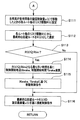
次に、運転支援装置2で実行される運転支援制御プログラムを図2、図3のフローチャートで説明する。
まず、ステップ(以下、「S」と略称)101で必要パラメータ、具体的には、白線データ、道路に沿って存在するガードレール、縁石等の側壁データ、及び、立体物データ(種別、自車両1からの距離、中心位置(xobstacle,yobstacle)、速度(vxobstacle,vyobstacle)等)の各データを読み込む。
Next, the driving support control program executed by the
First, in step (hereinafter, abbreviated as “S”) 101, necessary parameters, specifically, white line data, side data of guardrails, curbs, etc. existing along the road, and three-dimensional object data (type,
次に、S102に進み、白線(ガードレール、側壁も白線と同等に扱うものとする)を対象とする現在のリスク関数Rlineを、以下の(1)式により、演算する。
Rline=Kline・y2 …(1)
ここで、Klineは、予め設定したゲインである。すなわち、白線を対象とする現在のリスク関数Rlineは、図4に示すように、左右の白線(ガードレール、側壁も白線と同等に扱う)で認識される走行路の中心を、中心軸とする2次関数で与えられる。尚、本実施の形態では、リスク関数Rlineを2次の関数としているが、リスク関数Rlineは、走行路の中心から白線に近いほど、より大きなリスク値を導く関数であれば良く、例えば、4次或いは6次の関数とすることもできる。また、本実施の形態では、ガードレール、側壁も白線と同等に扱って2次関数のリスク関数Rlineを与えるようにしているが、ガードレール、側壁の場合は、白線に対するリスク関数Rlineとは異なる関数に変更し、白線の場合よりも大きなリスク値を導くようにしても良い。例えば、左右の白線に対するリスク関数Rlineを2次関数で与えた場合、カードレール、側壁に対しては4次或いは6次の関数に変更する。また、同じ2次関数であっても、ゲインKlineの値を大きな値に変更するようにしても良い。さらに、白線に対するリスク関数Rlineは、走行路の中心を中心軸とする例に限らず、中心軸をオフセットさせて、左側と右側の白線とでリスク値を互いに異ならせるようにしても良い。
Next, the process proceeds to S102, and the current risk function Rline for the white line (the guard rail and the side wall are handled in the same way as the white line) is calculated by the following equation (1).
Rline = Kline · y 2 (1)
Here, Kline is a preset gain. That is, as shown in FIG. 4, the current risk function Rline for the white line is 2 centered on the center of the road recognized by the left and right white lines (guardrails and side walls are also treated as white lines). Is given by In the present embodiment, the risk function Rline is a quadratic function. However, the risk function Rline may be a function that leads to a larger risk value as it approaches the white line from the center of the road, for example, 4 It can also be a second or sixth order function. In the present embodiment, the guard rail and the side wall are also treated in the same way as the white line so as to give a risk function Rline of a quadratic function. However, in the case of the guardrail and the side wall, a function different from the risk function Rline for the white line It may be changed so that a larger risk value is derived than in the case of the white line. For example, when the risk function Rline for the left and right white lines is given by a quadratic function, the card rail and the side wall are changed to a quartic or sixth-order function. Further, even for the same quadratic function, the value of the gain Kline may be changed to a large value. Furthermore, the risk function Rline for the white line is not limited to the example in which the center of the travel path is the central axis, but the central axis may be offset so that the risk values differ between the left and right white lines.
次いで、S103に進み、立体物(2輪車、普通車両、大型車両、歩行者、電柱等その他の立体物)を対象とする現在のリスク関数Robstacleを、以下の(2)式により、演算する。
Robstacle=Kobstacle・exp(−((xobstacle−x)2/(2・σxobstacle2))
−((yobstacle−y)2/(2・σyobstacle2))) …(2)
ここで、Kobstacleは、予め設定したゲインである。また、σxobstacleは予め設定しておいた対象のX軸方向の分散を示し、σyobstacleは、予め設定しておいた対象のY軸方向の分散を示し、これら分散σxobstacle、σyobstacleは、例えば、ステレオカメラ3による認識精度が低いほど大きく設定するようにしても良い。また、分散σxobstacle、σyobstacleは、対象の種別が、普通車両及び大型車両の場合を基準として、歩行者、2輪車である場合は大きく設定し、それ以外の立体物の場合は小さく設定するようにしても良い。更に、自車両1と対象となる立体物の幅方向のラップ率に応じて設定するようにしても良い。図4中、立体物A1及び立体物A2は、上述の(2)式により演算した立体物を対象とする現在のリスク関数Robstacleの一例である。
Next, the process proceeds to S103, and the current risk function Robstacle for a three-dimensional object (two-wheeled vehicle, ordinary vehicle, large vehicle, pedestrian, electric pole or other three-dimensional object) is calculated by the following equation (2). .
Robstacle = Kobstacle · exp (− ((xobstacle−x) 2 / (2 · σxobstacle 2 ))
− ((Yobstacle-y) 2 / (2 · σyobstacle 2 ))) (2)
Here, Kobstacle is a preset gain. Also, σxobstacle indicates the dispersion in the X-axis direction of the object set in advance, σyobstacle indicates the dispersion in the Y-axis direction of the object set in advance, and these dispersions σxobstacle and σyobstacle are, for example, a stereo camera The smaller the recognition accuracy by 3, the larger the setting may be. Also, the variances σxobstacle and σyobstacle should be set larger when the target type is a pedestrian or two-wheeled vehicle, and smaller when it is a three-dimensional object. Anyway. Furthermore, you may make it set according to the lap | wrap rate of the width direction of the
次に、S104に進み、現在のトータルリスク関数Rを、以下の(3)式により、演算する。
R=Rline+Robstacle …(3)
Next, it progresses to S104 and the present total risk function R is calculated by the following (3) Formula.
R = Rline + Robstacle (3)
次いで、S105に進み、t秒後の立体物位置(xobstacle(t),yobstacle(t))を、以下の(4)式により推定する。
(xobstacle(t),yobstacle(t))
=(xobstacle+vxobstacle・t,yobstacle+vyobstacle・t) …(4)
Next, in S105, the position of the three-dimensional object (xobstacle (t), yobstacle (t)) after t seconds is estimated by the following equation (4).
(Xobstacle (t), yobstacle (t))
= (Xobstacle + vxobstacle.t, yobstacle + vyobstacle.t) (4)
次に、S106に進み、上述のS105で推定したt秒後の立体物位置(xobstacle(t),yobstacle(t))を、上述のS104で演算したトータルリスク関数Rのx及びyにそれぞれ代入し、t秒後のトータルリスク関数R(xobstacle(t),yobstacle(t))を設定する。 Next, the process proceeds to S106, and the position of the three-dimensional object (xobstacle (t), yobstacle (t)) estimated in S105 is substituted into x and y of the total risk function R calculated in S104. Then, the total risk function R (xobstacle (t), yobstacle (t)) after t seconds is set.
次いで、S107に進み、上述のS106で設定したt秒後のトータルリスク関数R(xobstacle(t),yobstacle(t))を、幅方向(y方向)で偏微分して、その値が0となる点から幅方向(y方向)の極小点ymin(x,t)を演算する。すなわち、
∂R(xobstacle(t),yobstacle(t))/∂y=0 …(5)
となる点が極小点である。
Subsequently, the process proceeds to S107, and the total risk function R (xobstacle (t), yobstacle (t)) after t seconds set in S106 is partially differentiated in the width direction (y direction), and the value is 0. From this point, the minimum point ymin (x, t) in the width direction (y direction) is calculated. That is,
∂R (xobstacle (t), yobstacle (t)) / ∂y = 0 (5)
The point that becomes is the minimum point.
次に、S108に進み、t秒後の自車位置(X(t),Y(t))を、以下の(6)式により推定する。
(X(t),Y(t))=(V・t,V・∫sinψ(τ)dτ;積分範囲は0≦τ≦t)
…(6)
ここで、ψ(t)は、自車両1のヨー角であり、以下の(7)式により、演算される。
ψ(t)=(dψ/dt)・t
+(1/2)・((d2ψ/dt2)+(u(t)/Iz))・t2 …(7)
ここで、Izは、ヨー慣性モーメントである。また、u(t)は前述の如く旋回制御量であり、付加ヨーモーメントである。
Next, proceeding to S108, the vehicle position (X (t), Y (t)) after t seconds is estimated by the following equation (6).
(X (t), Y (t)) = (V · t, V · ∫sinψ (τ) dτ; integration range is 0 ≦ τ ≦ t)
(6)
Here, ψ (t) is the yaw angle of the
ψ (t) = (dψ / dt) · t
+ (1/2) · ((d 2 ψ / dt 2 ) + (u (t) / Iz)) · t 2 (7)
Here, Iz is the yaw moment of inertia. U (t) is the turning control amount as described above, and is the additional yaw moment.
次いで、S109に進み、上述のS107で演算したy方向の極小点ymin(x,t)に、上述のS108で推定した自車位置を代入し、自車位置X(t)における極小点ymin(X(t),t)を演算する。 Then, the process proceeds to S109, the minimum point in the y direction calculated in S107 described above ymin (x, t), by substituting the vehicle position estimated in S10 8 above, minimum point ymin at the vehicle position X (t) Calculate (X (t), t).
次に、S110に進み、各時間毎の自車の横位置Y(t)と極小点ymin(X(t),t)の偏差と旋回制御量u(t)で各目的関数Jを作成し、それぞれの目的関数Jについて目的関数Jを最少とする各時間毎の旋回制御量u(t)を求める。 Next, the process proceeds to S110, and each objective function J is created by the deviation of the lateral position Y (t) of the own vehicle and the minimum point ymin (X (t), t) and the turning control amount u (t) for each time. For each objective function J, a turn control amount u (t) for each time that minimizes the objective function J is obtained.
例えば、図5に示すように、自車両1が時刻0(現在)〜Δtまで移動する範囲を制御対象領域と考え、この間を、dtで分割し、1dt、2dt、3dt、…、mdt、…、(n−2)dt、(n−1)dt、ndt(=Δt)とする例を考える。
For example, as shown in FIG. 5, a range in which the
時刻0〜1dtの間には、例えば、以下(8)式の目的関数J0~1dtを設定し、この目的関数J0~1dtを最少とする旋回制御量u(0)を周知の最適化計算により求める。
J0~1dt=Wy・(ymin(X(1dt),1dt)−Y(1dt))2+Wu・u(0)2 …(8)
ここで、Wy、Wuは予め設定する重み値である。
Between
J0 ~ 1dt = Wy · (ymin (X (1dt), 1dt) −Y (1dt)) 2 + Wu · u (0) 2 (8)
Here, Wy and Wu are preset weight values.
また、時刻1dt〜2dtの間には、例えば、以下(9)式の目的関数J1dt~2dtを設定し、この目的関数J1dt~2dtを最少とする旋回制御量u(1dt)を周知の最適化計算により求める。
J1dt~2dt=Wy・(ymin(X(2dt),2dt)−Y(2dt))2+Wu・u(1dt)2 …(9)
Further, for example, objective functions J1dt to 2dt of the following equation (9) are set between times 1dt and 2dt, and the turning control amount u (1dt) that minimizes the objective functions J1dt to 2dt is well known and optimized. Obtain by calculation.
J1dt ~ 2dt = Wy · (ymin (X (2dt), 2dt) −Y (2dt)) 2 + Wu · u (1dt) 2 (9)
更に、時刻2dt〜3dtの間には、例えば、以下(10)式の目的関数J2dt~3dtを設定し、この目的関数J2dt~3dtを最少とする旋回制御量u(2dt)を周知の最適化計算により求める。
J2dt~3dt=Wy・(ymin(X(3dt),3dt)−Y(3dt))2+Wu・u(2dt)2 …(10)
尚、時刻3dtには極小点が2つ存在するため、旋回制御量u(2dt)も2つの値が得られる。
Further, for example, the objective function J2dt to 3dt of the following equation (10) is set between the times 2dt to 3dt, and the turning control amount u (2dt) that minimizes the objective function J2dt to 3dt is well-known optimized. Obtain by calculation.
J2dt ~ 3dt = Wy · (ymin (X (3dt), 3dt) −Y (3dt)) 2 + Wu · u (2dt) 2 (10)
Since there are two minimum points at time 3dt, two values are also obtained for the turning control amount u (2dt).
以下、時刻3dt以降も同様の目的関数を設定し、旋回制御量を求め、時刻(n−1)dt〜ndtの間には、例えば、以下(11)式の目的関数J(n-1)dt~ndtを設定し、この目的関数J(n-1)dt~ndtを最少とする旋回制御量u((n-1)dt)を周知の最適化計算により求める。
J(n-1)dt~ndt=Wy・(ymin(X(ndt),ndt)−Y(ndt))2
+Wu・u((n-1)dt)2 …(11)
Hereinafter, the same objective function is set after time 3dt, the turning control amount is obtained, and, for example, the objective function J (n-1) of the following equation (11) between times (n-1) dt and ndt. dt ~ ndt is set, and the turning control amount u ((n-1) dt) that minimizes the objective function J (n-1) dt ~ ndt is obtained by a known optimization calculation.
J (n-1) dt ~ ndt = Wy. (Ymin (X (ndt), ndt) -Y (ndt)) 2
+ Wu · u ((n-1) dt) 2 (11)
次いで、S111に進み、以下の(12)式により、自車両1が各時間毎の旋回制御量u(t)で移動したときの各ルート毎のリスク関数R(t)を設定する。
Next, the process proceeds to S111, and the risk function R (t) for each route when the
R(t)=Rline+Robstacle …(12)
ここで、Rline、及び、Robstacleは、前述の(1)式、及び、(2)式に、自車両1が各時間毎の旋回制御量u(t)で移動したときの値で与えられるものであり、
Rline=Kline・Y(t)2 …(13)
Robstacle=Kobstacle・exp(−((xobstacle(t)−X(t))2
/(2・σxobstacle2))−((yobstacle(t)−Y(t))2
/(2・σyobstacle2))) …(14)
次いで、S112に進み、S111で設定した各ルート毎のリスク関数R(t)から最終的な回避ルートをR(t)fとして選択する。
R (t) = Rline + Robstacle (12)
Here, Rline and Robstacle are given by the values obtained when the
Rline = Kline · Y (t) 2 (13)
Robstacle = Kobstacle · exp (− ((xobstacle (t) −X (t)) 2
/ (2 · σxobstacle 2 ))-((yobstacle (t) -Y (t)) 2
/ (2 · σyobstacle 2 ))) (14)
Next, the process proceeds to S112, and a final avoidance route is selected as R (t) f from the risk function R (t) for each route set in S111.
具体的には、S111で設定した各ルート毎にその最大値Rmaxを求める。すなわち、
Rmax=max(R(t))(0≦t≦Δt) …(15)
そして、最大値Rmaxの最も小さなルートを最終的な回避ルートR(t)fとして選択する。
Specifically, the maximum value Rmax is obtained for each route set in S111. That is,
Rmax = max (R (t)) (0 ≦ t ≦ Δt) (15)
Then, the route with the smallest maximum value Rmax is selected as the final avoidance route R (t) f.
尚、各ルート毎にリスクの累積値Rsum(=∫R(t)dt;積分範囲は0≦t≦Δt)を求め、その値が最も小さなルートを最終的な回避ルートR(t)fとして選択するようにしても良い。 A cumulative risk value Rsum (= ∫R (t) dt; integration range is 0 ≦ t ≦ Δt) is obtained for each route, and a route having the smallest value is defined as a final avoidance route R (t) f. You may make it select.
また、上述のS112において、S111で設定されたルートが1つのみしか存在しない場合は、そのルートが最終的な回避ルートR(t)fとして設定される。 In S112 described above, if there is only one route set in S111, that route is set as the final avoidance route R (t) f.
例えば、図5に示す例では、S111の処理により、実線で示すルート1と破線で示すルート2とが設定され、S112の処理により、これらルート1,2から最大値Rmaxが小さなルート、或いは、リスクの累積値Rsumが小さなルートが最終的な回避ルートR(t)fとして選択される。尚、ルート1,2のそれぞれの旋回制御量u(t)は、図5(b)に示す通りである。
For example, in the example shown in FIG. 5, the
そして、S113に進み、最終的な回避ルートR(t)fに予め定めておいた最大許容リスク値Rlim以上(R(t)f≧Rlim)となる領域が有るか否か判定し、R(t)f≧Rlimとなる領域がない場合は、S116に進んで、自動操舵制御装置23に対して最終的な回避ルートR(t)fの旋回制御量u(t)を基に操舵制御指令を出力してプログラムを抜ける。
Then, the process proceeds to S113, where it is determined whether or not there is a region that is equal to or greater than the predetermined maximum allowable risk value Rlim (R (t) f ≧ Rlim) in the final avoidance route R (t) f, and R ( t) If there is no region where f ≧ Rlim, the routine proceeds to S116, where the steering control command is issued to the automatic
また、S113の判定の結果、R(t)f≧Rlimとなる領域があると判定した場合は、S114に進み、R(t)f≧Rlimとなる最も早い時間を基に制動開始地点Xbrake、制動開始時間Tbrakeを演算する。 As a result of the determination in S113, if it is determined that there is a region where R (t) f ≧ Rlim, the process proceeds to S114, and the braking start point Xbrake, based on the earliest time when R (t) f ≧ Rlim is satisfied. The braking start time Tbrake is calculated.
R(t)f≧Rlimとなる最も早い時間をTmとすると、制動開始地点Xbrakeは、以下の(16)式により、演算される。
Xbrake=X(Tm)−Bx …(16)
ここで、Bxは予め設定しておいた減速度Gによる制動距離であり、以下の(17)式により演算される。
Bx=(V2/(2・G))+Bx0 …(17)
ここで、Bx0は、予め設定しておいた停止時における障害物までの距離であり、例えば、2m程度の値である。
Assuming that the earliest time when R (t) f ≧ Rlim is Tm, the braking start point Xbrake is calculated by the following equation (16).
Xbrake = X (Tm) −Bx (16)
Here, Bx is a braking distance by the deceleration G set in advance, and is calculated by the following equation (17).
Bx = (V 2 /(2.G))+Bx0 (17)
Here, Bx0 is a preset distance to the obstacle when the vehicle is stopped, and is a value of about 2 m, for example.
また、制動開始時間Tbrakeは、上述の制動開始地点Xbrakeから逆算することにより演算される。 The braking start time Tbrake is calculated by calculating backward from the above-described braking start point Xbrake.
次いで、S115に進み、自動ブレーキ制御装置22に対し、制動開始地点Xbrake、制動開始時間Tbrakeに基づく制動制御指令を出力する。
Next, in S115, a braking control command based on the braking start point Xbrake and the braking start time Tbrake is output to the automatic
そして、S116に進み、自動操舵制御装置23に対して最終的な回避ルートR(t)fの旋回制御量u(t)を基に操舵制御指令を出力してプログラムを抜ける。
In S116, a steering control command is output to the automatic
このように本発明の実施の形態によれば、前方に存在する白線、ガードレール、側壁、及び、立体物のそれぞれを対象として、現在のトータルリスク関数Rを設定し、各対象の位置の時間的変化を予測してトータルリスク関数Rの時間的変化を予測して、このトータルリスク関数Rの時間的変化を基に、各時間毎の自車位置におけるY軸方向の極小点ymin(x,t)を演算する。そして、各時間毎の目的関数Jを作成し、該目的関数Jを最小とする各時間毎の旋回制御量u(t)を自車両1の旋回制御量u(t)として演算して、自車両1が各時間毎の旋回制御量u(t)で移動したときの各ルート毎のリスク関数R(t)を設定し、各ルート毎のリスク関数R(t)から最終的な回避ルートR(t)fを選択し、最終的な回避ルートR(t)fの旋回制御量u(t)に基づいて操舵制御を実行させ、また、最終的な回避ルートR(t)fの値に基づいてブレーキ制御を実行させる。このため、目前の危険性だけではなく、その先に訪れる危険性をも考慮して衝突回避制御を実現することができる。
As described above, according to the embodiment of the present invention, the current total risk function R is set for each of the white line, the guardrail, the side wall, and the three-dimensional object existing in front, and the time of the position of each target is determined. A change is predicted to predict a temporal change of the total risk function R, and based on the temporal change of the total risk function R, a local minimum point ymin (x, t ) Is calculated. Then, an objective function J for each time is created, and the turn control amount u (t) for each time that minimizes the objective function J is calculated as the turn control amount u (t) of the
尚、本実施の形態では、最終的な回避ルートR(t)fを基にブレーキ制御と操舵制御の2つが行える例を説明しているが、どちらか1つを行うものであっても良い。 In the present embodiment, an example in which brake control and steering control can be performed based on the final avoidance route R (t) f has been described, but either one may be performed. .
また、本実施の形態で説明したブレーキ制御は、あくまでもその一例であり、他の周知のブレーキ制御、例えば、スロットル開度の閉鎖や自動変速機におけるシフトダウンと併用するようにしても良い。 The brake control described in this embodiment is merely an example, and may be used in combination with other well-known brake control, for example, closing of the throttle opening or downshifting in an automatic transmission.
更に、本実施の形態では、周辺環境をステレオカメラ3からの撮像画像を基に認識するようになっているが、他に、単眼カメラ、ミリ波レーダ等で検出するものであっても良い。 Furthermore, in this embodiment, the surrounding environment is recognized based on the captured image from the stereo camera 3, but it may also be detected by a monocular camera, millimeter wave radar, or the like.
また、本実施の形態では、自車両1の前方における白線や立体物等を対象として、現在のトータルリスク関数Rを設定し、その時間的変化を予測する構成について述べたが、これに限らず、自車両1の側方や側後方の立体物をも対象として、トータルリスク関数Rの設定やその時間的変化を予測するようにしても良い。
In the present embodiment, the current total risk function R is set for a white line or a three-dimensional object in front of the
さらに、本実施の形態では、自車両1の前進時において回避ルートを生成する構成について述べたが、これに限らず、自車両1の後方環境を認識して自車両1の後退時に回避ルートを生成するようにしても良い。
Furthermore, in the present embodiment, the configuration for generating the avoidance route when the
1 自車両
2 運転支援装置
3 ステレオカメラ(周辺環境認識手段)
4 ステレオ画像認識装置(周辺環境認識手段)
5 制御ユニット(危険度設定手段、危険度変化予測手段、極小点演算手段、旋回制御量演算手段、回避ルート決定手段)
11 車速センサ
12 ヨーレートセンサ
13 メインスイッチ
21 ディスプレイ
22 自動ブレーキ制御装置(制動制御手段)
23 自動操舵制御装置(操舵制御手段)
DESCRIPTION OF
4 Stereo image recognition device (peripheral environment recognition means)
5 Control unit (risk level setting means, risk level change prediction means, minimum point calculation means, turning control amount calculation means, avoidance route determination means)
11
23 Automatic steering control device (steering control means)
Claims (6)
上記認識した周辺環境の各対象に現在の危険度を設定する危険度設定手段と、
上記各対象の危険度を加算するとともに、上記危険度を設定した各対象の位置の時間的変化を予測して上記加算した危険度の時間的変化を予測する危険度変化予測手段と、
上記予測した危険度の時間的変化を基に、各時間での自車両の位置毎に該位置での現在の自車幅方向における危険度から危険度の極小点を演算する極小点演算手段と、
少なくとも上記各極小点に基づいて自車両の旋回制御量を演算する旋回制御量演算手段と、
上記旋回制御量に基づいて自車両の回避ルートを生成して最終的な回避ルートを決定する回避ルート決定手段と、
を備えたことを特徴とする車両の運転支援装置。 A surrounding environment recognition means for recognizing the surrounding environment of the host vehicle;
Risk level setting means for setting the current risk level for each of the recognized surrounding environment objects;
With adding the risk of each subject, and the risk change estimating means predicts the temporal change in the position of each object set the risk for predicting the temporal change of the degree of risk to the addition,
Based on the temporal change of the degree of risk to the prediction, the minimum point calculating means for calculating a minimum point of risk from risk at current vehicle width direction at the position for each position of the vehicle at each time ,
A turning control amount calculating means for calculating a turning control amount of the host vehicle based on at least each minimum point;
Avoidance route determination means for generating an avoidance route of the host vehicle based on the turning control amount and determining a final avoidance route;
A vehicle driving support apparatus comprising:
Priority Applications (2)
| Application Number | Priority Date | Filing Date | Title |
|---|---|---|---|
| JP2007033893A JP4949063B2 (en) | 2007-02-14 | 2007-02-14 | Vehicle driving support device |
| US12/155,927 US8224564B2 (en) | 2007-02-14 | 2008-06-11 | Vehicle drive assist system |
Applications Claiming Priority (1)
| Application Number | Priority Date | Filing Date | Title |
|---|---|---|---|
| JP2007033893A JP4949063B2 (en) | 2007-02-14 | 2007-02-14 | Vehicle driving support device |
Publications (2)
| Publication Number | Publication Date |
|---|---|
| JP2008195289A JP2008195289A (en) | 2008-08-28 |
| JP4949063B2 true JP4949063B2 (en) | 2012-06-06 |
Family
ID=39754633
Family Applications (1)
| Application Number | Title | Priority Date | Filing Date |
|---|---|---|---|
| JP2007033893A Active JP4949063B2 (en) | 2007-02-14 | 2007-02-14 | Vehicle driving support device |
Country Status (1)
| Country | Link |
|---|---|
| JP (1) | JP4949063B2 (en) |
Cited By (3)
| Publication number | Priority date | Publication date | Assignee | Title |
|---|---|---|---|---|
| US10860028B2 (en) | 2017-08-14 | 2020-12-08 | Honda Motor Co., Ltd. | Vehicle control apparatus, vehicle control method, and program |
| US10921143B2 (en) | 2017-06-20 | 2021-02-16 | Kabushiki Kaisha Toshiba | Information processing device, mobile object, information processing method, and computer program product |
| US11136027B2 (en) | 2017-05-25 | 2021-10-05 | Honda Motor Co., Ltd. | Vehicle control device |
Families Citing this family (15)
| Publication number | Priority date | Publication date | Assignee | Title |
|---|---|---|---|---|
| JP5402203B2 (en) * | 2009-04-20 | 2014-01-29 | トヨタ自動車株式会社 | Vehicle control apparatus and vehicle control method |
| CN102449672B (en) | 2009-06-02 | 2013-05-01 | 丰田自动车株式会社 | Vehicular peripheral surveillance device |
| JP5824968B2 (en) * | 2011-08-24 | 2015-12-02 | 日産自動車株式会社 | Travel control device |
| US9606539B1 (en) | 2015-11-04 | 2017-03-28 | Zoox, Inc. | Autonomous vehicle fleet service and system |
| US10401852B2 (en) | 2015-11-04 | 2019-09-03 | Zoox, Inc. | Teleoperation system and method for trajectory modification of autonomous vehicles |
| JP6962926B2 (en) * | 2015-11-04 | 2021-11-05 | ズークス インコーポレイテッド | Remote control systems and methods for trajectory correction of autonomous vehicles |
| WO2017079341A2 (en) | 2015-11-04 | 2017-05-11 | Zoox, Inc. | Automated extraction of semantic information to enhance incremental mapping modifications for robotic vehicles |
| US11283877B2 (en) | 2015-11-04 | 2022-03-22 | Zoox, Inc. | Software application and logic to modify configuration of an autonomous vehicle |
| US9630619B1 (en) | 2015-11-04 | 2017-04-25 | Zoox, Inc. | Robotic vehicle active safety systems and methods |
| US9632502B1 (en) * | 2015-11-04 | 2017-04-25 | Zoox, Inc. | Machine-learning systems and techniques to optimize teleoperation and/or planner decisions |
| JP6859902B2 (en) | 2017-08-31 | 2021-04-14 | トヨタ自動車株式会社 | Vehicle control unit |
| KR102553730B1 (en) * | 2018-03-08 | 2023-07-11 | 주식회사 에이치엘클레무브 | Apparatus and method for controlling collision avoidance of vehicle |
| JP7145815B2 (en) * | 2019-05-27 | 2022-10-03 | 日立Astemo株式会社 | electronic controller |
| JP7289760B2 (en) * | 2019-09-18 | 2023-06-12 | 日立Astemo株式会社 | electronic controller |
| JP7388238B2 (en) * | 2020-02-21 | 2023-11-29 | トヨタ自動車株式会社 | driving assistance system |
Family Cites Families (3)
| Publication number | Priority date | Publication date | Assignee | Title |
|---|---|---|---|---|
| JP3210121B2 (en) * | 1992-02-10 | 2001-09-17 | 本田技研工業株式会社 | Obstacle avoidance route search method for moving objects |
| JP4604683B2 (en) * | 2004-11-25 | 2011-01-05 | 日産自動車株式会社 | Hazardous situation warning device |
| WO2006070865A1 (en) * | 2004-12-28 | 2006-07-06 | Kabushiki Kaisha Toyota Chuo Kenkyusho | Vehicle motion control device |
-
2007
- 2007-02-14 JP JP2007033893A patent/JP4949063B2/en active Active
Cited By (3)
| Publication number | Priority date | Publication date | Assignee | Title |
|---|---|---|---|---|
| US11136027B2 (en) | 2017-05-25 | 2021-10-05 | Honda Motor Co., Ltd. | Vehicle control device |
| US10921143B2 (en) | 2017-06-20 | 2021-02-16 | Kabushiki Kaisha Toshiba | Information processing device, mobile object, information processing method, and computer program product |
| US10860028B2 (en) | 2017-08-14 | 2020-12-08 | Honda Motor Co., Ltd. | Vehicle control apparatus, vehicle control method, and program |
Also Published As
| Publication number | Publication date |
|---|---|
| JP2008195289A (en) | 2008-08-28 |
Similar Documents
| Publication | Publication Date | Title |
|---|---|---|
| JP4949063B2 (en) | Vehicle driving support device | |
| JP4970156B2 (en) | Vehicle driving support device | |
| US11703876B2 (en) | Autonomous driving system | |
| JP5167051B2 (en) | Vehicle driving support device | |
| US8224564B2 (en) | Vehicle drive assist system | |
| JP4980076B2 (en) | Vehicle driving support device | |
| JP5066478B2 (en) | Vehicle driving support device | |
| JP5345350B2 (en) | Vehicle driving support device | |
| JP2018095143A (en) | Vehicle control device | |
| JP2010018062A (en) | Vehicle driving support device | |
| JP2009286279A (en) | Drive support device for vehicle | |
| WO2019039275A1 (en) | Vehicle control device | |
| JP2017068461A (en) | Vehicle driving assistance device | |
| JP6494020B2 (en) | Vehicle driving support control device | |
| JP5210064B2 (en) | Vehicle collision prevention device | |
| JP5452004B2 (en) | Vehicle driving support device | |
| CN112714718B (en) | Vehicle control method and vehicle control device | |
| JP5249696B2 (en) | Vehicle driving support device | |
| JP6609292B2 (en) | Outside environment recognition device | |
| JP5336800B2 (en) | Vehicle driving support device | |
| JP4204830B2 (en) | Vehicle driving support device | |
| CN113544023B (en) | Vehicle travel control method and travel control device | |
| JP5261045B2 (en) | Vehicle driving support device | |
| JP5083959B2 (en) | Vehicle driving support device | |
| JP4626295B2 (en) | Driving support system and driving support device |
Legal Events
| Date | Code | Title | Description |
|---|---|---|---|
| A621 | Written request for application examination |
Free format text: JAPANESE INTERMEDIATE CODE: A621 Effective date: 20100204 |
|
| A131 | Notification of reasons for refusal |
Free format text: JAPANESE INTERMEDIATE CODE: A131 Effective date: 20111122 |
|
| A521 | Request for written amendment filed |
Free format text: JAPANESE INTERMEDIATE CODE: A523 Effective date: 20120105 |
|
| TRDD | Decision of grant or rejection written | ||
| A01 | Written decision to grant a patent or to grant a registration (utility model) |
Free format text: JAPANESE INTERMEDIATE CODE: A01 Effective date: 20120221 |
|
| A01 | Written decision to grant a patent or to grant a registration (utility model) |
Free format text: JAPANESE INTERMEDIATE CODE: A01 |
|
| A61 | First payment of annual fees (during grant procedure) |
Free format text: JAPANESE INTERMEDIATE CODE: A61 Effective date: 20120307 |
|
| FPAY | Renewal fee payment (event date is renewal date of database) |
Free format text: PAYMENT UNTIL: 20150316 Year of fee payment: 3 |
|
| R150 | Certificate of patent or registration of utility model |
Free format text: JAPANESE INTERMEDIATE CODE: R150 Ref document number: 4949063 Country of ref document: JP Free format text: JAPANESE INTERMEDIATE CODE: R150 |
|
| S531 | Written request for registration of change of domicile |
Free format text: JAPANESE INTERMEDIATE CODE: R313531 |
|
| R350 | Written notification of registration of transfer |
Free format text: JAPANESE INTERMEDIATE CODE: R350 |
|
| R250 | Receipt of annual fees |
Free format text: JAPANESE INTERMEDIATE CODE: R250 |
|
| R250 | Receipt of annual fees |
Free format text: JAPANESE INTERMEDIATE CODE: R250 |
|
| R250 | Receipt of annual fees |
Free format text: JAPANESE INTERMEDIATE CODE: R250 |
|
| S533 | Written request for registration of change of name |
Free format text: JAPANESE INTERMEDIATE CODE: R313533 |
|
| R350 | Written notification of registration of transfer |
Free format text: JAPANESE INTERMEDIATE CODE: R350 |
|
| R250 | Receipt of annual fees |
Free format text: JAPANESE INTERMEDIATE CODE: R250 |
|
| R250 | Receipt of annual fees |
Free format text: JAPANESE INTERMEDIATE CODE: R250 |
|
| R250 | Receipt of annual fees |
Free format text: JAPANESE INTERMEDIATE CODE: R250 |
|
| R250 | Receipt of annual fees |
Free format text: JAPANESE INTERMEDIATE CODE: R250 |
|
| R250 | Receipt of annual fees |
Free format text: JAPANESE INTERMEDIATE CODE: R250 |
|
| R250 | Receipt of annual fees |
Free format text: JAPANESE INTERMEDIATE CODE: R250 |
|
| R250 | Receipt of annual fees |
Free format text: JAPANESE INTERMEDIATE CODE: R250 |