EP3370404B1 - Bildlesegerät - Google Patents
Bildlesegerät Download PDFInfo
- Publication number
- EP3370404B1 EP3370404B1 EP16859813.4A EP16859813A EP3370404B1 EP 3370404 B1 EP3370404 B1 EP 3370404B1 EP 16859813 A EP16859813 A EP 16859813A EP 3370404 B1 EP3370404 B1 EP 3370404B1
- Authority
- EP
- European Patent Office
- Prior art keywords
- flat cable
- scanning direction
- image reading
- reading unit
- sub
- Prior art date
- Legal status (The legal status is an assumption and is not a legal conclusion. Google has not performed a legal analysis and makes no representation as to the accuracy of the status listed.)
- Active
Links
Images







Classifications
-
- H—ELECTRICITY
- H04—ELECTRIC COMMUNICATION TECHNIQUE
- H04N—PICTORIAL COMMUNICATION, e.g. TELEVISION
- H04N1/00—Scanning, transmission or reproduction of documents or the like, e.g. facsimile transmission; Details thereof
- H04N1/00976—Arrangements for regulating environment, e.g. removing static electricity
-
- G—PHYSICS
- G03—PHOTOGRAPHY; CINEMATOGRAPHY; ANALOGOUS TECHNIQUES USING WAVES OTHER THAN OPTICAL WAVES; ELECTROGRAPHY; HOLOGRAPHY
- G03B—APPARATUS OR ARRANGEMENTS FOR TAKING PHOTOGRAPHS OR FOR PROJECTING OR VIEWING THEM; APPARATUS OR ARRANGEMENTS EMPLOYING ANALOGOUS TECHNIQUES USING WAVES OTHER THAN OPTICAL WAVES; ACCESSORIES THEREFOR
- G03B27/00—Photographic printing apparatus
- G03B27/32—Projection printing apparatus, e.g. enlarger, copying camera
- G03B27/50—Projection printing apparatus, e.g. enlarger, copying camera with slit or like diaphragm moving over original for progressive exposure
-
- G—PHYSICS
- G03—PHOTOGRAPHY; CINEMATOGRAPHY; ANALOGOUS TECHNIQUES USING WAVES OTHER THAN OPTICAL WAVES; ELECTROGRAPHY; HOLOGRAPHY
- G03G—ELECTROGRAPHY; ELECTROPHOTOGRAPHY; MAGNETOGRAPHY
- G03G15/00—Apparatus for electrographic processes using a charge pattern
- G03G15/04—Apparatus for electrographic processes using a charge pattern for exposing, i.e. imagewise exposure by optically projecting the original image on a photoconductive recording material
-
- H—ELECTRICITY
- H04—ELECTRIC COMMUNICATION TECHNIQUE
- H04N—PICTORIAL COMMUNICATION, e.g. TELEVISION
- H04N1/00—Scanning, transmission or reproduction of documents or the like, e.g. facsimile transmission; Details thereof
- H04N1/00519—Constructional details not otherwise provided for, e.g. housings, covers
- H04N1/00557—Connection or assembly of components or elements
-
- H—ELECTRICITY
- H04—ELECTRIC COMMUNICATION TECHNIQUE
- H04N—PICTORIAL COMMUNICATION, e.g. TELEVISION
- H04N1/00—Scanning, transmission or reproduction of documents or the like, e.g. facsimile transmission; Details thereof
- H04N1/024—Details of scanning heads ; Means for illuminating the original
-
- H—ELECTRICITY
- H04—ELECTRIC COMMUNICATION TECHNIQUE
- H04N—PICTORIAL COMMUNICATION, e.g. TELEVISION
- H04N1/00—Scanning, transmission or reproduction of documents or the like, e.g. facsimile transmission; Details thereof
- H04N1/04—Scanning arrangements, i.e. arrangements for the displacement of active reading or reproducing elements relative to the original or reproducing medium, or vice versa
- H04N1/047—Detection, control or error compensation of scanning velocity or position
- H04N1/0473—Detection, control or error compensation of scanning velocity or position in subscanning direction, e.g. picture start or line-to-line synchronisation
-
- H—ELECTRICITY
- H04—ELECTRIC COMMUNICATION TECHNIQUE
- H04N—PICTORIAL COMMUNICATION, e.g. TELEVISION
- H04N1/00—Scanning, transmission or reproduction of documents or the like, e.g. facsimile transmission; Details thereof
- H04N1/04—Scanning arrangements, i.e. arrangements for the displacement of active reading or reproducing elements relative to the original or reproducing medium, or vice versa
- H04N1/06—Scanning arrangements, i.e. arrangements for the displacement of active reading or reproducing elements relative to the original or reproducing medium, or vice versa using cylindrical picture-bearing surfaces, i.e. scanning a main-scanning line substantially perpendicular to the axis and lying in a curved cylindrical surface
- H04N1/0671—Scanning arrangements, i.e. arrangements for the displacement of active reading or reproducing elements relative to the original or reproducing medium, or vice versa using cylindrical picture-bearing surfaces, i.e. scanning a main-scanning line substantially perpendicular to the axis and lying in a curved cylindrical surface with sub-scanning by translational movement of the main-scanning components
- H04N1/0685—Scanning arrangements, i.e. arrangements for the displacement of active reading or reproducing elements relative to the original or reproducing medium, or vice versa using cylindrical picture-bearing surfaces, i.e. scanning a main-scanning line substantially perpendicular to the axis and lying in a curved cylindrical surface with sub-scanning by translational movement of the main-scanning components using a belt or cable
-
- H—ELECTRICITY
- H04—ELECTRIC COMMUNICATION TECHNIQUE
- H04N—PICTORIAL COMMUNICATION, e.g. TELEVISION
- H04N1/00—Scanning, transmission or reproduction of documents or the like, e.g. facsimile transmission; Details thereof
- H04N1/04—Scanning arrangements, i.e. arrangements for the displacement of active reading or reproducing elements relative to the original or reproducing medium, or vice versa
- H04N1/10—Scanning arrangements, i.e. arrangements for the displacement of active reading or reproducing elements relative to the original or reproducing medium, or vice versa using flat picture-bearing surfaces
- H04N1/1013—Scanning arrangements, i.e. arrangements for the displacement of active reading or reproducing elements relative to the original or reproducing medium, or vice versa using flat picture-bearing surfaces with sub-scanning by translatory movement of at least a part of the main-scanning components
- H04N1/1026—Scanning arrangements, i.e. arrangements for the displacement of active reading or reproducing elements relative to the original or reproducing medium, or vice versa using flat picture-bearing surfaces with sub-scanning by translatory movement of at least a part of the main-scanning components using a belt or cable
-
- H—ELECTRICITY
- H04—ELECTRIC COMMUNICATION TECHNIQUE
- H04N—PICTORIAL COMMUNICATION, e.g. TELEVISION
- H04N1/00—Scanning, transmission or reproduction of documents or the like, e.g. facsimile transmission; Details thereof
- H04N1/0083—Arrangements for transferring signals between different components of the apparatus, e.g. arrangements of signal lines or cables
-
- H—ELECTRICITY
- H04—ELECTRIC COMMUNICATION TECHNIQUE
- H04N—PICTORIAL COMMUNICATION, e.g. TELEVISION
- H04N1/00—Scanning, transmission or reproduction of documents or the like, e.g. facsimile transmission; Details thereof
- H04N1/04—Scanning arrangements, i.e. arrangements for the displacement of active reading or reproducing elements relative to the original or reproducing medium, or vice versa
-
- H—ELECTRICITY
- H04—ELECTRIC COMMUNICATION TECHNIQUE
- H04N—PICTORIAL COMMUNICATION, e.g. TELEVISION
- H04N1/00—Scanning, transmission or reproduction of documents or the like, e.g. facsimile transmission; Details thereof
- H04N1/04—Scanning arrangements, i.e. arrangements for the displacement of active reading or reproducing elements relative to the original or reproducing medium, or vice versa
- H04N1/10—Scanning arrangements, i.e. arrangements for the displacement of active reading or reproducing elements relative to the original or reproducing medium, or vice versa using flat picture-bearing surfaces
- H04N1/1061—Details relating to flat picture-bearing surfaces, e.g. transparent platen
- H04N1/1065—Support or mounting of the flat picture-bearing surface
Definitions
- the present invention relates to an image reading device.
- an image reading device including a housing mounted at an upper surface thereof with a document table glass and an image reading unit configured to be received in the housing to be movable in a sub-scanning direction perpendicular to a main scanning direction.
- the aforementioned image reading unit has a light source, which emits light toward the document table glass, and the like.
- the image reading unit is connected to a fixed board, which is fixed to a bottom wall of the housing, via a flat cable. One end part of the flat cable is connected to the image reading unit and the other end part thereof is connected to the aforementioned fixed board.
- the flat cable includes a flexible member and forms an U shape having an upper sidewall part, a lower sidewall part, and a curved part that connects the both sidewall parts to each other when viewed from the main scanning direction. With the movement of the image reading unit, the flat cable is deformed while increasing/decreasing a curvature radius of the curved part.
- US 2012/0026558 A1 discloses an image forming apparatus provided with a document receiving portion that receives a document, and an image reader that moves between a first end position of the document receiving portion and a second end position opposite to the first end position.
- a cable is provided having an end connected to the image reader.
- a cable protrusion and a regulation protrusion are con-figured such that, along with movement of the image reader in the predetermined direction from the first position to the second position, the cable protrusion moves a predetermined distance in the predetermined direction and contacts the regulation protrusion, and the regulation protrusion regulates a further movement of the cable in the predetermined direction.
- US 2001/0040705 A1 discloses an image reading apparatus including an image reading unit for reading image information of an original resting on an original resting portion, wherein, at the time of reading, the image reading unit moves along the original resting portion, and a flat cable electrically connecting the image reading unit to the main body of the image reading apparatus to transmit the image information read by the image reading unit to the main body of the image reading apparatus, wherein the width direction of the flat cable includes a component in a direction perpendicular to the original resting surface.
- US 2014/0376068 A1 discloses an image reading apparatus including an image scanning unit that is provided with a holding portion holding a flexible flat cable.
- the holding portion is protruded toward an upstream side in a sub scanning direction, and provided with a second wall part.
- the flexible flat cable that is extended from a connector is brought into contact with the second wall part.
- a downward movement is regulated by a lower holding portion and an upward movement is regulated by an upper holding portion. Accordingly, the flexible flat cable does not rise.
- US 2009244655 A1 discloses an image reading device having a housing, a trans-parent panel, an image sensor, a carriage, and an electric cable.
- the electric cable is electrically connected to the image sensor, and includes a band surface portion having a band surface.
- the electric cable also has a first end portion attached to the carriage; and a second end portion attached to a second surface. At least a portion of the electric cable is twisted such that the band surface and a third surface are not parallel.
- Patent Literature 1 Japanese Unexamined Patent Application Publication No. 2004-273435
- the present invention has been made in view of such problems, and an object of the present invention is to reliably suppress a speed variation of an image reading unit due to frictional resistance or electrostatic attraction force between a flat cable and a document table glass by using a simple configuration.
- the present invention it is possible to reliably suppress a speed variation of an image reading unit due to frictional resistance or electrostatic attraction force between a flat cable and a document table glass by using a simple configuration.
- Fig. 1 illustrates an image forming apparatus 1 including an image reading device 200 of the present embodiment.
- the image forming apparatus 1 is so-called an in-body sheet discharge type copy machine and has an image forming apparatus body 100, the image reading device 200, and a support casing 300.
- the image reading device 200 reads a document image to acquire image data thereof.
- the image data acquired by the image reading device 200 is printed on a sheet P.
- the image reading device 200 is supported to an upper side of the image forming apparatus body 100 via the support casing 300. Between the image forming apparatus body 100 and the image reading device 200, a sheet discharge space S is formed.
- the image reading device 200 is provided at a lateral side thereof with an operation panel 205 for allowing a user to give various operation instructions to the image forming apparatus 1 (see Fig. 1 ).
- a side at which the operation panel 205 is positioned in the image forming apparatus 1 is defined as a "front side” and an opposite side thereof is defined as a “rear side”.
- a "left side” and a “right side” indicate a left side and a right side when the image forming apparatus 1 is viewed from the front side.
- an image forming unit 30 is received inside the image forming apparatus body 100.
- the image forming unit 30 is arranged in the vicinity of a right sidewall part in a lower part of the image forming apparatus body 100.
- a sheet feeding unit 10 is provided, and above the image forming unit 30, a fixing unit 40 is provided.
- the sheet feeding unit 10 has a sheet feeding cassette 10a for receiving a sheet-shaped sheet P, and a pick-up roller 10b for taking out the sheet P in the sheet feeding cassette 10a and sending the taken-out sheet P outside the cassette 10a.
- the sheet P sent outside the sheet feeding cassette 10a is supplied to the image forming unit 30 via a conveying roller pair 11.
- the image forming unit 30 has a photosensitive drum 21, a charging device 23, an exposing device 25, a developing device 27, and a transfer device 29.
- a peripheral surface of the photosensitive drum 21 is first charged by the charging device 23, and then laser light based on document image data (image data of the document image read by the image reading device 200) is irradiated to the surface of the photosensitive drum 21 by the exposing device 25, so that an electrostatic latent image is formed.
- This electrostatic latent image is developed by the developing device 27 and becomes a toner image.
- This toner image is transferred to the sheet P by the transfer device 29 when the sheet P passes through between the transfer device 29 and the photosensitive drum 21.
- the fixing unit 40 has a fixing roller 40a and a pressure roller 40b, and presses the sheet P supplied by the transfer device 29 between the fixing roller 40a and the pressure roller 40b, thereby thermally fixing the toner image to the sheet P.
- the sheet P with the toner image fixed by the fixing unit 40 is led to the sheet discharge space S by conveying roller pairs 12 and 13.
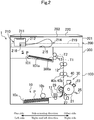
- the aforementioned image reading device 200 has a rectangular box-shaped housing 201 that receives an image reading unit 210 therein.
- the aforementioned housing 201 is formed at an upper surface thereof with an approximately rectangular opening, wherein a document table glass 203 is fitted into the opening.
- a document cover 220 is supported via a hinge part (not illustrated) so as to be openable and closable. In a closed state, the document cover 220 presses a document placed on the document table glass 203 from an upper side, thereby fixing the document.
- the aforementioned image reading unit 210 is arranged between the document table glass 203 mounted at the housing 201 and a bottom wall part of the housing 201.
- the image reading unit 210 moves while emitting light toward the document table glass 203 and optically reads an image of a document placed on the document table glass 203, thereby generating image data thereof and storing the image data in a memory.
- the image reading unit 210 has a contact image sensor (CIS) 211 and a carriage 212 that holds the contact image sensor 211.
- CIS contact image sensor
- the contact image sensor 211 is mounted at an upper surface part of the carriage 212.
- the contact image sensor 211 has a light source for irradiating light toward the document table glass 203, a plurality of elements for receiving reflected light from the light source, performing photoelectrical conversion on the reflected light, and outputting the converted electrical signals (image signals), and the like.
- the electrical signals outputted from each element of the contact image sensor 211 are transmitted to a fixed board via a flat cable 214 (see Fig. 3 ) to be described later.
- the carriage 212 forms a shape obtained by notching a part of a rectangular parallelepiped extending in a main scanning direction.
- the carriage 212 is supported to be movable in a sub-scanning direction by a rail member 219 (illustrated only in Fig. 2 and is not illustrated in other drawings) extending in the sub-scanning direction.
- the carriage 212 is reciprocally driven between a predetermined initial position (so-called a home position and a position indicated by a solid line of Fig. 3 ) and a termination position (a position indicated by a two dot chain line of Fig. 3 ) by a driving mechanism (not illustrated).
- This initial position is positioned at one side end part (a left end part) of the rail member 219 in the sub-scanning direction and the termination position is positioned at the other side end part (a right end part) of the rail member 219 in the sub-scanning direction.
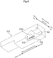
- the carriage 212 is formed at the other side surface thereof in the sub-scanning direction with a rectangular parallelepiped-shaped notched part C1 opened to the other side in the sub-scanning direction and one side (the rear side of the image forming apparatus 1 in the present embodiment) in the main scanning direction.
- a connecting connector 216 protrudes from a wall surface directed to the other side in the sub-scanning direction among three sidewall surfaces forming the notched part C1.
- a concave part 212i having a V shape when viewed from the sub-scanning direction is formed.
- One inclination surface (an angle restriction part) 212a constituting the concave part 212i is positioned above the connecting connector 216, and is upwardly inclined toward one side from the other side in the main scanning direction. This inclination angle is set to a range of about 25 ° to about 35 ° in the present embodiment.
- the inclination surface 212a is positioned above the connecting connector 216. Furthermore, the inclination surface 212a is formed to face an upper sidewall part 214a of the flat cable 214 to be described later.
- the connecting connector 216 is formed in a rectangular parallelepiped shape extending in parallel to the main scanning direction. A connecting port of the connecting connector 216 is directed to the other side in the sub-scanning direction. The connecting connector 216 is electrically connected to the aforementioned contact image sensor 211 in the inside of the carriage 212.
- the flat cable 214 is a belt-like cable having flexibility.
- the flat cable 214 includes a signal line for transmitting image data outputted from the contact image sensor 211, a power supply line for supplying power to the image reading unit 210, and the like.
- the flat cable 214 is curved in an U shape when viewed from the main scanning direction. That is, the flat cable 214 has the upper sidewall part 214a and a lower sidewall part 214b, which face each other in an up and down direction, and a curved part 214c, which connects parts of the both wall parts 214a and 214b (right side end parts) to each other, when viewed from the main scanning direction.
- the flat cable 214 is bent while increasing and decreasing a curvature radius R of the curved part 214c with the movement of the carriage 212 (the image reading unit 210).
- the carriage 212 In the reading operation of a document image by the image reading device 200, the carriage 212 is driven from the one side to the other side in the sub-scanning direction by the driving mechanism (not illustrated) starting from the predetermined initial position (the position indicated by the solid line of Fig. 3 ), and is stopped at the termination position (the position indicated by the two dot chain line of Fig. 3 ).
- image data of the document at each scanning position is acquired by the contact image sensor 211.
- the image data of the document at each scanning position acquired by the contact image sensor 211 is transmitted to an image processing circuit on the fixed board 215 via the flat cable 214. In the image processing circuit, these pieces of image data are synthesized with each other to generate image data of the entire document, and the generated image data is stored in a memory.
- the carriage 212 is moved to the termination position by the driving mechanism and then is returned to the initial position.
- the upper sidewall part 214a of the flat cable 214 contacts with the document table glass 203.
- a predetermined value for example, 1/2 of a distance between the lower surface of the document table glass 203 and the bottom wall part of the housing
- the upper sidewall part 214a of the flat cable 214 contacts with the inclination surface 212a formed at the upper side of the connecting connector 216 of the carriage 212. Since this inclination surface 212a is upwardly inclined toward one side from the other side in the main scanning direction, the inclination angle ⁇ of the upper sidewall part 214a of the flat cable 214 with respect to the document table glass 203 is restricted to the same angle as that of the inclination surface 212a as illustrated in Fig. 6 . As a consequence, a contact portion between the upper sidewall part 214a of the flat cable 214 and the document table glass 203 is biased to one side of the flat cable 214 in the main scanning direction.
- Fig. 7 illustrates a modification example 1 of the aforementioned example 1.
- a plate-like protruding wall part 212b is formed at the other side surface of the carriage 212 in the sub-scanning direction, so that the inclination surface 212a is formed. That is, the protruding wall part 212b is upwardly inclined from the one side toward the other side in the main scanning direction, so that the inclination surface 212a serves as a lower side surface of the protruding wall part 212b.
- Fig. 8 illustrates an example 2 for explaning features of the present invention.
- This example 2 is different from the aforementioned example 1 and the modification example in that the angle restriction part for restricting the angle of the flat cable 214 is configured by the connecting connector 216 itself.
- the connecting connector 216 is upwardly inclined toward one side from the other side in the main scanning direction.
- the upper sidewall part 214a of the flat cable 214 connected to the connecting connector 216 is upwardly inclined from the one side toward the other side in the main scanning direction. Consequently, when the curvature radius R of the curved part 214c of the flat cable 214 increases during the movement of the carriage 212 and the upper sidewall part 214a of the flat cable 214 contacts with the document table glass 203, contact portions of the both can be biased to one side of the flat cable 214 in the main scanning direction. Thus, it is possible to obtain operation and effect similar to those of the aforementioned example 1. Furthermore, as compared with the example 1, it is possible to simplify the shape of the carriage 212, so that it is possible to improve moldability of the carriage 212.
- Fig. 9 illustrates an example 3 for explaning features of the present invention.
- This example 3 is different from the aforementioned each example and the modification example in that the angle restriction part for restricting the angle of the flat cable 214 is formed by an insertion hole 212d.
- the carriage 212 is formed at a lower end part thereof with a rectangular parallelepiped-shaped notched part C2 which is opened downward and to one side in the main scanning direction.
- a connecting connector 216 protrudes from a wall surface directed to the other side in the sub-scanning direction among four sidewall surfaces forming the notched part C2 .
- a slit-like insertion hole 212d is formed at a vertical wall part 212c facing the connecting connector 216. This insertion hole 212d is upwardly inclined toward one side from the other side in the main scanning direction.
- the upper sidewall part 214a of the flat cable 214 connected to the connecting connector 216 is always inclined from the one side toward the other side in the main scanning direction. Consequently, when the curvature radius R of the curved part 214c of the flat cable 214 increases during the movement of the carriage 212 and the flat cable 214 contacts with the document table glass 203, contact portions of the both can be biased to one side of the flat cable 214 in the main scanning direction. Thus, it is possible to obtain operation and effect similar to those of the aforementioned example 1.
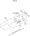
- Fig. 10 illustrates an example 4 for explaning features of the present invention. This example is different from the aforementioned each example and the modification example in that the angle restriction part for restricting the angle of the flat cable 214 is formed by a vertical wall part 212c.
- the vertical wall part 212c of the present example has a first wall part 212e extending in the main scanning direction and a second wall part 212f connected to the other side end part of the first wall part 212e in the main scanning direction.
- This second wall part 212f is provided at an insertion side of the flat cable 214 with respect to the connecting connector 216.
- the second wall part 212f is formed with a slit-like insertion hole 212d into which the upper sidewall part 214a of the flat cable 214 is inserted.
- a surface of the second wall part 212f, which is opposite to the connecting connector 216 side, is inclined to the connecting connector 216 side (one side in the sub-scanning direction) toward one side from the other side in the main scanning direction.
- the second wall part 212f is allowed to be inclined, so that one side portion of the upper sidewall part 214a of the flat cable 214 in the main scanning direction is easily turned up as compared with the other side portion. Consequently, the curvature radius R of the curved part 214c of the flat cable 214 increases and the upper sidewall part 214a of the flat cable 214 contacts with the document table glass 203, contact portions of the both can be biased to one side of the flat cable 214 in the main scanning direction. Thus, it is possible to obtain operation and effect similar to those of the aforementioned example 1.
- Fig. 11 illustrates an example 5 for explaning features of the present invention. This example is different from the aforementioned each example and the modification example in that the angle restriction part for restricting the angle of the flat cable 214 is formed by a protruding wall part 212g.
- the protruding wall part 212g is formed to protrude from a wall part provided with the connecting connector 216 and to face the upper sidewall part 214a (not illustrated in Fig. 11 ) of the flat cable 214.
- An end edge of the protruding side of the protruding wall part 212g is inclined to the aforementioned connecting connector 216 side toward one side from the other side in the main scanning direction. According to this configuration, one side portion of the upper wall part of the flat cable 214 in the main scanning direction is easily turned up as compared with the other side portion.
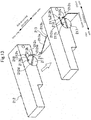
- Fig. 12 and Fig. 13 illustrate an embodiment 1.
- This embodiment is different from the aforementioned each example and the modification example in that the inclination angle of the flat cable 214 can be changed by an angle restriction part during reciprocal movement of the carriage 212.
- one side in the main scanning direction is defined as the rear side of the image forming apparatus 1 and the other side in the main scanning direction is defined as the front side of the image forming apparatus 1; however, in the present embodiment, one side in the main scanning direction is defined as the front side of the image forming apparatus 1 and the other side in the main scanning direction is defined as the rear side of the image forming apparatus 1.
- the definition of the sub-scanning direction is similar to that of the aforementioned each example and the modification example.
- the angle restriction part includes a rotating part 217 supported to the carriage 212, a protruding part 217a formed at the rotating part 217, and a restricting rail 213 (illustrated only in Fig. 13 ) abutting the protruding part 217a to restrict a rotation angle of the rotating part 217.
- the rotating part 217 is formed in a disc shape in which a shaft line extends in the sub-scanning direction.
- the rotating part 217 is provided to the insertion side of the flat cable 214 with respect to the connecting connector 216.
- the rotating part 217 is supported to the carriage 212 so as to be rotatable around the shaft line.
- the rotating part 217 is formed with a slit-like insertion hole 212d into which the flat cable 214 is inserted.
- the insertion hole 212d passes through the rotating part 217 in a thickness direction (the sub-scanning direction) of the rotating part 217.
- an engagement protruding part 217b From a surface of the rotating part 217, which is opposite to the connecting connector 216 side, an engagement protruding part 217b, with which one end part of an urging spring 218 is engaged, protrudes.
- the urging spring 218 includes a tension coil spring in the present embodiment.
- the other end part of the urging spring 218 is engaged with an engagement protruding part 212h protruding from the vertical wall part 212c of the carriage 212.
- the aforementioned insertion hole 212d is upwardly inclined toward one side from the other side in the main scanning direction.
- the aforementioned protruding part 217a includes a plate-like part protruding radially outside from an outer peripheral surface of the rotating part 217. A thickness direction of this plate-like part coincides with a circumferential direction of the rotating part 217.
- the vertical wall part 212c is formed at a lower end part thereof with an arc-shaped guide concave part 212m through which the protruding part 217a passes with the rotation of the rotating part 217.
- An end surface 212k of one side in the circumferential direction of the guide concave part 212m abuts the protruding part 217a to restrict the rotation of the rotating part 217.
- the insertion hole 212d is parallel (that is, horizontal) to the main scanning direction.
- the restricting rail 213 includes a vertical plate extending in the sub-scanning direction.
- the restricting rail 213 is provided in the vicinity of the termination position of the carriage 212. That is, the restricting rail 213 is provided in an area (hereinafter, referred to as a termination vicinity area) where the curvature radius R of the curved part 214c of the flat cable 214 becomes equal to or less than a predetermined radius in the movement range of the carriage 212.
- An upper end edge of the restricting rail 213 includes an inclination edge part 213a and a horizontal edge part 213b.
- the inclination edge part 213a is formed at an end part of one side in the sub-scanning direction.
- the inclination edge part 213a is upwardly inclined from the one side toward the other side in the main scanning direction.
- the other side end of the inclination edge part 213a in the sub-scanning direction is connected to the horizontal edge part 213b.
- the horizontal edge part 213b horizontally extends from the one side toward the other side in the sub-scanning direction.
- the carriage 212 in the state in which the carriage 212 exists in the initial position, the carriage 212 is positioned at one side in the sub-scanning direction than the restricting rail 213, and the insertion hole 212d is upwardly inclined toward one side from the other side in the main scanning direction. Consequently, the upper sidewall part 214a of the flat cable 214 inserted into the insertion hole 212d becomes upwardly inclined toward one side from the other side in the main scanning direction.
- the insertion hole 212d is parallel (that is, horizontal) to the document table glass 203. Consequently, the upper sidewall part 214a of the flat cable 214 inserted into the insertion hole 212d is also parallel to the document table glass 203. Thereafter, before the carriage 212 reaches the termination vicinity position, since the protruding part 217a horizontally moves while sliding along the horizontal edge part 213b, the upper sidewall part 214a of the flat cable 214 maintains the parallel relation to the document table glass 203.
- the configuration of the present invention can also be provided to an image reading device 200 in which an image sensor such as the contact image sensor 211 is not installed at the carriage 212.
- an image sensor such as the contact image sensor 211 is not installed at the carriage 212.
- the present invention is useful for an image reading device.
Landscapes
- Engineering & Computer Science (AREA)
- Multimedia (AREA)
- Signal Processing (AREA)
- Physics & Mathematics (AREA)
- General Physics & Mathematics (AREA)
- Environmental & Geological Engineering (AREA)
- Optics & Photonics (AREA)
- Facsimile Scanning Arrangements (AREA)
- Optical Systems Of Projection Type Copiers (AREA)
Claims (1)
- Bildlesevorrichtung (200), die aufweist:ein Gehäuse (201), an einer Oberfläche von dem eine Dokumentenglasplatte (203) montiert ist;eine Bildleseeinheit (210), die Licht zur Dokumentenglasplatte (203) emittiert, während sie sich in einer Unterabtastrichtung wechselseitig lotrecht zu einer Hauptabtastrichtung zwischen einem Bodenwandteil des Gehäuses (201) und der Dokumentenglasplatte (203) bewegt; undein Flachkabel (214), von dem ein Endteil mit der Bildleseeinheit (210) verbunden ist, während das andere Endteil am Bodenwandteil des Gehäuses (201) befestigt ist, und das in einer U-Form angeordnet ist, die in der Hauptabtastrichtung gesehen aus einem oberen Seitenwandteil (214a), einem unteren Seitenwandteil (214b) und einem gekrümmten Teil (214c) zur Verbindung beider Seitenwandteile (214a, 214b) besteht,wobei die Bildlesevorrichtung (200) weiter aufweist:ein Winkelbegrenzungsteil (212a), das in der Unterabtastrichtung des Flachkabels (214) gesehen einen Neigungswinkel des Flachkabels (214) bezüglich der Dokumentenglasplatte (203) begrenzt, so dass, wenn ein Kontaktabschnitt zwischen einem Oberflächenteil des Flachkabels (214) und der Dokumentenglasplatte (203) mit der Bewegung der Bildleseeinheit (210) erzeugt wird, der Kontaktabschnitt zu einer Seite des Flachkabels (214) in der Hauptabtastrichtung vorgespannt wird, wobei das Winkelbegrenzungsteil (212a) konfiguriert ist, den Neigungswinkel des Flachkabels (214) zu verringern, wenn ein Krümmungsradius (R) des gekrümmten Teils (214c) des Flachkabels (214) während der wechselseitigen Bewegung der Bildleseeinheit (210) verringert wird,dadurch gekennzeichnet, dass das Winkelbegrenzungsteil (212a) aufweist:ein drehendes Teil (217) mit einem schlitzartigen Einführloch (212d), das in der Unterabtastrichtung durchgeht und in das das Flachkabel (214) eingeführt wird, und das drehende Teil (217) so zur Bildleseeinheit (210) gehalten wird, dass es um eine sich in der Unterabtastrichtung erstreckende Achslinie drehbar ist;ein vorstehendes Teil (217a), das von einer Außenumfangsfläche des drehenden Teils (217) radial außen vorsteht;eine Begrenzungsschiene (213), die am Bodenwandteil des Gehäuses (201) befestigt ist und sich in der Unterabtastrichtung erstreckt; undein Neigungskantenteil (213a), das in der Begrenzungsschiene (213) geformt ist und von der einen zur anderen Seite in der Unterabtastrichtung nach oben geneigt ist,wobei, wenn eine Stellung der Bildleseeinheit (210) in einem Bereich existiert, in dem der Krümmungsradius (R) des gekrümmten Teils (214c) des Flachkabels (214) gleich oder weniger als ein vorbestimmter Radius wird, während der Krümmungsradius (R) des gekrümmten Teils (214c) mit der Bewegung der Bildleseeinheit (210) verringert wird, das vorstehende Teil (217a) durch das Neigungskantenteil (213a) nach oben gedrückt und das drehende Teil (217) in einer Richtung gedreht wird, in der der Neigungswinkel des Flachkabels (214) verringert ist.
Applications Claiming Priority (2)
| Application Number | Priority Date | Filing Date | Title |
|---|---|---|---|
| JP2015214858 | 2015-10-30 | ||
| PCT/JP2016/081645 WO2017073583A1 (ja) | 2015-10-30 | 2016-10-25 | 画像読取装置 |
Publications (3)
| Publication Number | Publication Date |
|---|---|
| EP3370404A1 EP3370404A1 (de) | 2018-09-05 |
| EP3370404A4 EP3370404A4 (de) | 2019-06-05 |
| EP3370404B1 true EP3370404B1 (de) | 2020-05-13 |
Family
ID=58630529
Family Applications (1)
| Application Number | Title | Priority Date | Filing Date |
|---|---|---|---|
| EP16859813.4A Active EP3370404B1 (de) | 2015-10-30 | 2016-10-25 | Bildlesegerät |
Country Status (5)
| Country | Link |
|---|---|
| US (1) | US10225427B2 (de) |
| EP (1) | EP3370404B1 (de) |
| JP (1) | JP6443647B2 (de) |
| CN (1) | CN107852442B (de) |
| WO (1) | WO2017073583A1 (de) |
Families Citing this family (1)
| Publication number | Priority date | Publication date | Assignee | Title |
|---|---|---|---|---|
| JP7412968B2 (ja) * | 2019-11-13 | 2024-01-15 | キヤノン株式会社 | 画像読取装置及び画像形成装置 |
Family Cites Families (15)
| Publication number | Priority date | Publication date | Assignee | Title |
|---|---|---|---|---|
| JP2001346006A (ja) * | 2000-03-31 | 2001-12-14 | Canon Inc | 画像読取装置 |
| CN2541981Y (zh) * | 2002-04-15 | 2003-03-26 | 力捷电脑(中国)有限公司 | 扫描仪柔性扁平电缆线走线结构 |
| JP3880966B2 (ja) | 2003-03-05 | 2007-02-14 | トランスパシフィック・プラズマ,リミテッド・ライアビリティ・カンパニー | 摩擦防止型フラットフレキシブルケーブル |
| CN1207686C (zh) * | 2003-05-14 | 2005-06-22 | 致伸科技股份有限公司 | 防磨擦装置与应用该装置的平台式扫描仪 |
| CN1306787C (zh) * | 2004-08-24 | 2007-03-21 | 宇东电浆科技股份有限公司 | 平台式扫描仪 |
| CN1867031A (zh) * | 2005-05-17 | 2006-11-22 | 明基电通股份有限公司 | 扫描仪 |
| JP4572946B2 (ja) | 2008-03-31 | 2010-11-04 | ブラザー工業株式会社 | 画像読取装置 |
| JP5370306B2 (ja) * | 2010-07-29 | 2013-12-18 | ブラザー工業株式会社 | 読取装置、画像形成装置 |
| JP2012083515A (ja) * | 2010-10-12 | 2012-04-26 | Seiko Epson Corp | 画像読取装置、複合機 |
| JP6228041B2 (ja) * | 2013-06-21 | 2017-11-08 | シャープ株式会社 | 画像読取装置及び画像形成装置 |
| JP6413417B2 (ja) * | 2014-07-15 | 2018-10-31 | 富士ゼロックス株式会社 | 画像読取装置 |
| JP6327202B2 (ja) * | 2015-05-25 | 2018-05-23 | 京セラドキュメントソリューションズ株式会社 | 画像読取装置 |
| JP6455385B2 (ja) * | 2015-09-30 | 2019-01-23 | コニカミノルタ株式会社 | 画像読取装置及び画像形成装置 |
| JP6740743B2 (ja) * | 2016-06-22 | 2020-08-19 | コニカミノルタ株式会社 | 画像読取装置及び画像形成装置 |
| JP6617698B2 (ja) * | 2016-12-28 | 2019-12-11 | 京セラドキュメントソリューションズ株式会社 | 画像読取装置および画像形成装置 |
-
2016
- 2016-10-25 US US15/749,811 patent/US10225427B2/en active Active
- 2016-10-25 EP EP16859813.4A patent/EP3370404B1/de active Active
- 2016-10-25 WO PCT/JP2016/081645 patent/WO2017073583A1/ja not_active Ceased
- 2016-10-25 CN CN201680044529.0A patent/CN107852442B/zh not_active Expired - Fee Related
- 2016-10-25 JP JP2017547810A patent/JP6443647B2/ja not_active Expired - Fee Related
Non-Patent Citations (1)
| Title |
|---|
| None * |
Also Published As
| Publication number | Publication date |
|---|---|
| EP3370404A4 (de) | 2019-06-05 |
| US20180227455A1 (en) | 2018-08-09 |
| WO2017073583A1 (ja) | 2017-05-04 |
| EP3370404A1 (de) | 2018-09-05 |
| CN107852442A (zh) | 2018-03-27 |
| US10225427B2 (en) | 2019-03-05 |
| CN107852442B (zh) | 2020-04-14 |
| JP6443647B2 (ja) | 2018-12-26 |
| JPWO2017073583A1 (ja) | 2018-05-24 |
Similar Documents
| Publication | Publication Date | Title |
|---|---|---|
| US9288349B2 (en) | Image processing device | |
| US11003403B2 (en) | Image reading device and image forming apparatus with personal authentication | |
| US10574844B2 (en) | Image reading device, document feeder device, and image forming apparatus | |
| US10432812B2 (en) | Image reading device, document feeder device, and image forming apparatus | |
| US10440193B2 (en) | Image reading device and image forming apparatus | |
| US10542168B2 (en) | Image reading device and image forming apparatus | |
| US11300917B2 (en) | Image forming apparatus | |
| CN104076639A (zh) | 图像形成装置 | |
| US7705873B2 (en) | Image forming apparatus and multi-function device | |
| US9316990B2 (en) | Motherboard mounting structure, image forming apparatus and method for performing the same | |
| EP3370404A1 (de) | Bildlesevorrichtung | |
| US11637943B2 (en) | Image reading apparatus and image forming apparatus | |
| CN108156348B (zh) | 图像读取装置以及图像形成装置 | |
| US10359733B2 (en) | Support member connection mechanism and electrical apparatus including the same | |
| US9342023B1 (en) | Image forming apparatus | |
| JP5746958B2 (ja) | 画像読取装置、およびこれを備えた画像形成装置 | |
| US7688484B2 (en) | Image-forming device having both an image-reading unit and an image-forming unit being made compact | |
| JP6489905B2 (ja) | 光学走査装置及び画像形成装置 | |
| JP2015141349A (ja) | 画像読取り装置、及び画像形成装置 | |
| JP2000131907A (ja) | 画像形成装置 | |
| JP2011091653A (ja) | 画像読取装置及び画像形成装置 |
Legal Events
| Date | Code | Title | Description |
|---|---|---|---|
| STAA | Information on the status of an ep patent application or granted ep patent |
Free format text: STATUS: THE INTERNATIONAL PUBLICATION HAS BEEN MADE |
|
| PUAI | Public reference made under article 153(3) epc to a published international application that has entered the european phase |
Free format text: ORIGINAL CODE: 0009012 |
|
| STAA | Information on the status of an ep patent application or granted ep patent |
Free format text: STATUS: REQUEST FOR EXAMINATION WAS MADE |
|
| 17P | Request for examination filed |
Effective date: 20180131 |
|
| AK | Designated contracting states |
Kind code of ref document: A1 Designated state(s): AL AT BE BG CH CY CZ DE DK EE ES FI FR GB GR HR HU IE IS IT LI LT LU LV MC MK MT NL NO PL PT RO RS SE SI SK SM TR |
|
| AX | Request for extension of the european patent |
Extension state: BA ME |
|
| DAV | Request for validation of the european patent (deleted) | ||
| DAX | Request for extension of the european patent (deleted) | ||
| REG | Reference to a national code |
Ref country code: DE Ref legal event code: R079 Ref document number: 602016036566 Country of ref document: DE Free format text: PREVIOUS MAIN CLASS: H04N0001040000 Ipc: H04N0001100000 |
|
| A4 | Supplementary search report drawn up and despatched |
Effective date: 20190503 |
|
| RIC1 | Information provided on ipc code assigned before grant |
Ipc: H04N 1/00 20060101ALI20190426BHEP Ipc: H04N 1/10 20060101AFI20190426BHEP Ipc: H04N 1/024 20060101ALI20190426BHEP Ipc: H04N 1/047 20060101ALI20190426BHEP Ipc: H04N 1/06 20060101ALI20190426BHEP Ipc: G03B 27/50 20060101ALI20190426BHEP Ipc: G03G 15/04 20060101ALI20190426BHEP Ipc: H04N 1/04 20060101ALI20190426BHEP |
|
| GRAP | Despatch of communication of intention to grant a patent |
Free format text: ORIGINAL CODE: EPIDOSNIGR1 |
|
| STAA | Information on the status of an ep patent application or granted ep patent |
Free format text: STATUS: GRANT OF PATENT IS INTENDED |
|
| INTG | Intention to grant announced |
Effective date: 20200116 |
|
| GRAS | Grant fee paid |
Free format text: ORIGINAL CODE: EPIDOSNIGR3 |
|
| GRAA | (expected) grant |
Free format text: ORIGINAL CODE: 0009210 |
|
| STAA | Information on the status of an ep patent application or granted ep patent |
Free format text: STATUS: THE PATENT HAS BEEN GRANTED |
|
| AK | Designated contracting states |
Kind code of ref document: B1 Designated state(s): AL AT BE BG CH CY CZ DE DK EE ES FI FR GB GR HR HU IE IS IT LI LT LU LV MC MK MT NL NO PL PT RO RS SE SI SK SM TR |
|
| REG | Reference to a national code |
Ref country code: GB Ref legal event code: FG4D |
|
| REG | Reference to a national code |
Ref country code: CH Ref legal event code: EP |
|
| REG | Reference to a national code |
Ref country code: DE Ref legal event code: R096 Ref document number: 602016036566 Country of ref document: DE |
|
| REG | Reference to a national code |
Ref country code: AT Ref legal event code: REF Ref document number: 1271754 Country of ref document: AT Kind code of ref document: T Effective date: 20200615 |
|
| REG | Reference to a national code |
Ref country code: LT Ref legal event code: MG4D |
|
| REG | Reference to a national code |
Ref country code: NL Ref legal event code: MP Effective date: 20200513 |
|
| PG25 | Lapsed in a contracting state [announced via postgrant information from national office to epo] |
Ref country code: SE Free format text: LAPSE BECAUSE OF FAILURE TO SUBMIT A TRANSLATION OF THE DESCRIPTION OR TO PAY THE FEE WITHIN THE PRESCRIBED TIME-LIMIT Effective date: 20200513 Ref country code: LT Free format text: LAPSE BECAUSE OF FAILURE TO SUBMIT A TRANSLATION OF THE DESCRIPTION OR TO PAY THE FEE WITHIN THE PRESCRIBED TIME-LIMIT Effective date: 20200513 Ref country code: FI Free format text: LAPSE BECAUSE OF FAILURE TO SUBMIT A TRANSLATION OF THE DESCRIPTION OR TO PAY THE FEE WITHIN THE PRESCRIBED TIME-LIMIT Effective date: 20200513 Ref country code: NO Free format text: LAPSE BECAUSE OF FAILURE TO SUBMIT A TRANSLATION OF THE DESCRIPTION OR TO PAY THE FEE WITHIN THE PRESCRIBED TIME-LIMIT Effective date: 20200813 Ref country code: GR Free format text: LAPSE BECAUSE OF FAILURE TO SUBMIT A TRANSLATION OF THE DESCRIPTION OR TO PAY THE FEE WITHIN THE PRESCRIBED TIME-LIMIT Effective date: 20200814 Ref country code: IS Free format text: LAPSE BECAUSE OF FAILURE TO SUBMIT A TRANSLATION OF THE DESCRIPTION OR TO PAY THE FEE WITHIN THE PRESCRIBED TIME-LIMIT Effective date: 20200913 Ref country code: PT Free format text: LAPSE BECAUSE OF FAILURE TO SUBMIT A TRANSLATION OF THE DESCRIPTION OR TO PAY THE FEE WITHIN THE PRESCRIBED TIME-LIMIT Effective date: 20200914 |
|
| PG25 | Lapsed in a contracting state [announced via postgrant information from national office to epo] |
Ref country code: LV Free format text: LAPSE BECAUSE OF FAILURE TO SUBMIT A TRANSLATION OF THE DESCRIPTION OR TO PAY THE FEE WITHIN THE PRESCRIBED TIME-LIMIT Effective date: 20200513 Ref country code: HR Free format text: LAPSE BECAUSE OF FAILURE TO SUBMIT A TRANSLATION OF THE DESCRIPTION OR TO PAY THE FEE WITHIN THE PRESCRIBED TIME-LIMIT Effective date: 20200513 Ref country code: RS Free format text: LAPSE BECAUSE OF FAILURE TO SUBMIT A TRANSLATION OF THE DESCRIPTION OR TO PAY THE FEE WITHIN THE PRESCRIBED TIME-LIMIT Effective date: 20200513 Ref country code: BG Free format text: LAPSE BECAUSE OF FAILURE TO SUBMIT A TRANSLATION OF THE DESCRIPTION OR TO PAY THE FEE WITHIN THE PRESCRIBED TIME-LIMIT Effective date: 20200813 |
|
| REG | Reference to a national code |
Ref country code: AT Ref legal event code: MK05 Ref document number: 1271754 Country of ref document: AT Kind code of ref document: T Effective date: 20200513 |
|
| PG25 | Lapsed in a contracting state [announced via postgrant information from national office to epo] |
Ref country code: AL Free format text: LAPSE BECAUSE OF FAILURE TO SUBMIT A TRANSLATION OF THE DESCRIPTION OR TO PAY THE FEE WITHIN THE PRESCRIBED TIME-LIMIT Effective date: 20200513 Ref country code: NL Free format text: LAPSE BECAUSE OF FAILURE TO SUBMIT A TRANSLATION OF THE DESCRIPTION OR TO PAY THE FEE WITHIN THE PRESCRIBED TIME-LIMIT Effective date: 20200513 |
|
| PG25 | Lapsed in a contracting state [announced via postgrant information from national office to epo] |
Ref country code: RO Free format text: LAPSE BECAUSE OF FAILURE TO SUBMIT A TRANSLATION OF THE DESCRIPTION OR TO PAY THE FEE WITHIN THE PRESCRIBED TIME-LIMIT Effective date: 20200513 Ref country code: CZ Free format text: LAPSE BECAUSE OF FAILURE TO SUBMIT A TRANSLATION OF THE DESCRIPTION OR TO PAY THE FEE WITHIN THE PRESCRIBED TIME-LIMIT Effective date: 20200513 Ref country code: ES Free format text: LAPSE BECAUSE OF FAILURE TO SUBMIT A TRANSLATION OF THE DESCRIPTION OR TO PAY THE FEE WITHIN THE PRESCRIBED TIME-LIMIT Effective date: 20200513 Ref country code: DK Free format text: LAPSE BECAUSE OF FAILURE TO SUBMIT A TRANSLATION OF THE DESCRIPTION OR TO PAY THE FEE WITHIN THE PRESCRIBED TIME-LIMIT Effective date: 20200513 Ref country code: IT Free format text: LAPSE BECAUSE OF FAILURE TO SUBMIT A TRANSLATION OF THE DESCRIPTION OR TO PAY THE FEE WITHIN THE PRESCRIBED TIME-LIMIT Effective date: 20200513 Ref country code: SM Free format text: LAPSE BECAUSE OF FAILURE TO SUBMIT A TRANSLATION OF THE DESCRIPTION OR TO PAY THE FEE WITHIN THE PRESCRIBED TIME-LIMIT Effective date: 20200513 Ref country code: EE Free format text: LAPSE BECAUSE OF FAILURE TO SUBMIT A TRANSLATION OF THE DESCRIPTION OR TO PAY THE FEE WITHIN THE PRESCRIBED TIME-LIMIT Effective date: 20200513 Ref country code: AT Free format text: LAPSE BECAUSE OF FAILURE TO SUBMIT A TRANSLATION OF THE DESCRIPTION OR TO PAY THE FEE WITHIN THE PRESCRIBED TIME-LIMIT Effective date: 20200513 |
|
| REG | Reference to a national code |
Ref country code: DE Ref legal event code: R097 Ref document number: 602016036566 Country of ref document: DE |
|
| PG25 | Lapsed in a contracting state [announced via postgrant information from national office to epo] |
Ref country code: PL Free format text: LAPSE BECAUSE OF FAILURE TO SUBMIT A TRANSLATION OF THE DESCRIPTION OR TO PAY THE FEE WITHIN THE PRESCRIBED TIME-LIMIT Effective date: 20200513 Ref country code: SK Free format text: LAPSE BECAUSE OF FAILURE TO SUBMIT A TRANSLATION OF THE DESCRIPTION OR TO PAY THE FEE WITHIN THE PRESCRIBED TIME-LIMIT Effective date: 20200513 |
|
| PLBE | No opposition filed within time limit |
Free format text: ORIGINAL CODE: 0009261 |
|
| STAA | Information on the status of an ep patent application or granted ep patent |
Free format text: STATUS: NO OPPOSITION FILED WITHIN TIME LIMIT |
|
| 26N | No opposition filed |
Effective date: 20210216 |
|
| PG25 | Lapsed in a contracting state [announced via postgrant information from national office to epo] |
Ref country code: SI Free format text: LAPSE BECAUSE OF FAILURE TO SUBMIT A TRANSLATION OF THE DESCRIPTION OR TO PAY THE FEE WITHIN THE PRESCRIBED TIME-LIMIT Effective date: 20200513 |
|
| REG | Reference to a national code |
Ref country code: CH Ref legal event code: PL |
|
| PG25 | Lapsed in a contracting state [announced via postgrant information from national office to epo] |
Ref country code: LU Free format text: LAPSE BECAUSE OF NON-PAYMENT OF DUE FEES Effective date: 20201025 Ref country code: MC Free format text: LAPSE BECAUSE OF FAILURE TO SUBMIT A TRANSLATION OF THE DESCRIPTION OR TO PAY THE FEE WITHIN THE PRESCRIBED TIME-LIMIT Effective date: 20200513 |
|
| REG | Reference to a national code |
Ref country code: BE Ref legal event code: MM Effective date: 20201031 |
|
| PG25 | Lapsed in a contracting state [announced via postgrant information from national office to epo] |
Ref country code: LI Free format text: LAPSE BECAUSE OF NON-PAYMENT OF DUE FEES Effective date: 20201031 Ref country code: CH Free format text: LAPSE BECAUSE OF NON-PAYMENT OF DUE FEES Effective date: 20201031 Ref country code: BE Free format text: LAPSE BECAUSE OF NON-PAYMENT OF DUE FEES Effective date: 20201031 |
|
| PG25 | Lapsed in a contracting state [announced via postgrant information from national office to epo] |
Ref country code: IE Free format text: LAPSE BECAUSE OF NON-PAYMENT OF DUE FEES Effective date: 20201025 |
|
| PG25 | Lapsed in a contracting state [announced via postgrant information from national office to epo] |
Ref country code: TR Free format text: LAPSE BECAUSE OF FAILURE TO SUBMIT A TRANSLATION OF THE DESCRIPTION OR TO PAY THE FEE WITHIN THE PRESCRIBED TIME-LIMIT Effective date: 20200513 Ref country code: MT Free format text: LAPSE BECAUSE OF FAILURE TO SUBMIT A TRANSLATION OF THE DESCRIPTION OR TO PAY THE FEE WITHIN THE PRESCRIBED TIME-LIMIT Effective date: 20200513 Ref country code: CY Free format text: LAPSE BECAUSE OF FAILURE TO SUBMIT A TRANSLATION OF THE DESCRIPTION OR TO PAY THE FEE WITHIN THE PRESCRIBED TIME-LIMIT Effective date: 20200513 |
|
| PG25 | Lapsed in a contracting state [announced via postgrant information from national office to epo] |
Ref country code: MK Free format text: LAPSE BECAUSE OF FAILURE TO SUBMIT A TRANSLATION OF THE DESCRIPTION OR TO PAY THE FEE WITHIN THE PRESCRIBED TIME-LIMIT Effective date: 20200513 |
|
| PGFP | Annual fee paid to national office [announced via postgrant information from national office to epo] |
Ref country code: FR Payment date: 20220920 Year of fee payment: 7 |
|
| PGFP | Annual fee paid to national office [announced via postgrant information from national office to epo] |
Ref country code: DE Payment date: 20220920 Year of fee payment: 7 |
|
| P01 | Opt-out of the competence of the unified patent court (upc) registered |
Effective date: 20230420 |
|
| PGFP | Annual fee paid to national office [announced via postgrant information from national office to epo] |
Ref country code: GB Payment date: 20230920 Year of fee payment: 8 |
|
| REG | Reference to a national code |
Ref country code: DE Ref legal event code: R119 Ref document number: 602016036566 Country of ref document: DE |
|
| PG25 | Lapsed in a contracting state [announced via postgrant information from national office to epo] |
Ref country code: FR Free format text: LAPSE BECAUSE OF NON-PAYMENT OF DUE FEES Effective date: 20231031 Ref country code: DE Free format text: LAPSE BECAUSE OF NON-PAYMENT OF DUE FEES Effective date: 20240501 |
|
| GBPC | Gb: european patent ceased through non-payment of renewal fee |
Effective date: 20241025 |
|
| PG25 | Lapsed in a contracting state [announced via postgrant information from national office to epo] |
Ref country code: GB Free format text: LAPSE BECAUSE OF NON-PAYMENT OF DUE FEES Effective date: 20241025 |