EP3370291A1 - Dispositif de pile à combustible, système de pile à combustible, procédé de commande de système de pile à combustible, et dispositif de commande - Google Patents
Dispositif de pile à combustible, système de pile à combustible, procédé de commande de système de pile à combustible, et dispositif de commande Download PDFInfo
- Publication number
- EP3370291A1 EP3370291A1 EP16859309.3A EP16859309A EP3370291A1 EP 3370291 A1 EP3370291 A1 EP 3370291A1 EP 16859309 A EP16859309 A EP 16859309A EP 3370291 A1 EP3370291 A1 EP 3370291A1
- Authority
- EP
- European Patent Office
- Prior art keywords
- slave
- master
- fuel cell
- apparatuses
- slave apparatus
- Prior art date
- Legal status (The legal status is an assumption and is not a legal conclusion. Google has not performed a legal analysis and makes no representation as to the accuracy of the status listed.)
- Granted
Links
- 239000000446 fuel Substances 0.000 title claims abstract description 109
- 238000000034 method Methods 0.000 title claims description 26
- 238000004891 communication Methods 0.000 claims abstract description 35
- 238000012423 maintenance Methods 0.000 claims description 6
- 230000005856 abnormality Effects 0.000 claims description 5
- 230000015556 catabolic process Effects 0.000 claims description 5
- 238000006731 degradation reaction Methods 0.000 claims description 5
- 230000004044 response Effects 0.000 description 23
- 230000008569 process Effects 0.000 description 11
- 238000010248 power generation Methods 0.000 description 6
- 230000005540 biological transmission Effects 0.000 description 5
- 238000010586 diagram Methods 0.000 description 4
- 238000012986 modification Methods 0.000 description 2
- 230000004048 modification Effects 0.000 description 2
- 101000849522 Saccharomyces cerevisiae (strain ATCC 204508 / S288c) 40S ribosomal protein S13 Proteins 0.000 description 1
- 238000013459 approach Methods 0.000 description 1
- 230000008901 benefit Effects 0.000 description 1
- 238000006243 chemical reaction Methods 0.000 description 1
- 230000001010 compromised effect Effects 0.000 description 1
- 230000003750 conditioning effect Effects 0.000 description 1
- 230000001419 dependent effect Effects 0.000 description 1
- 230000036541 health Effects 0.000 description 1
- 230000006872 improvement Effects 0.000 description 1
- 238000004519 manufacturing process Methods 0.000 description 1
- 239000005518 polymer electrolyte Substances 0.000 description 1
- 230000008439 repair process Effects 0.000 description 1
- 230000008054 signal transmission Effects 0.000 description 1
- 239000007787 solid Substances 0.000 description 1
- 230000007704 transition Effects 0.000 description 1
Images


Classifications
-
- H—ELECTRICITY
- H02—GENERATION; CONVERSION OR DISTRIBUTION OF ELECTRIC POWER
- H02J—CIRCUIT ARRANGEMENTS OR SYSTEMS FOR SUPPLYING OR DISTRIBUTING ELECTRIC POWER; SYSTEMS FOR STORING ELECTRIC ENERGY
- H02J3/00—Circuit arrangements for ac mains or ac distribution networks
- H02J3/38—Arrangements for parallely feeding a single network by two or more generators, converters or transformers
- H02J3/381—Dispersed generators
-
- H—ELECTRICITY
- H01—ELECTRIC ELEMENTS
- H01M—PROCESSES OR MEANS, e.g. BATTERIES, FOR THE DIRECT CONVERSION OF CHEMICAL ENERGY INTO ELECTRICAL ENERGY
- H01M8/00—Fuel cells; Manufacture thereof
- H01M8/04—Auxiliary arrangements, e.g. for control of pressure or for circulation of fluids
- H01M8/04298—Processes for controlling fuel cells or fuel cell systems
- H01M8/04694—Processes for controlling fuel cells or fuel cell systems characterised by variables to be controlled
- H01M8/04858—Electric variables
-
- H—ELECTRICITY
- H01—ELECTRIC ELEMENTS
- H01M—PROCESSES OR MEANS, e.g. BATTERIES, FOR THE DIRECT CONVERSION OF CHEMICAL ENERGY INTO ELECTRICAL ENERGY
- H01M8/00—Fuel cells; Manufacture thereof
- H01M8/04—Auxiliary arrangements, e.g. for control of pressure or for circulation of fluids
- H01M8/04298—Processes for controlling fuel cells or fuel cell systems
- H01M8/04313—Processes for controlling fuel cells or fuel cell systems characterised by the detection or assessment of variables; characterised by the detection or assessment of failure or abnormal function
- H01M8/04664—Failure or abnormal function
- H01M8/04679—Failure or abnormal function of fuel cell stacks
-
- H—ELECTRICITY
- H01—ELECTRIC ELEMENTS
- H01M—PROCESSES OR MEANS, e.g. BATTERIES, FOR THE DIRECT CONVERSION OF CHEMICAL ENERGY INTO ELECTRICAL ENERGY
- H01M8/00—Fuel cells; Manufacture thereof
- H01M8/04—Auxiliary arrangements, e.g. for control of pressure or for circulation of fluids
- H01M8/04298—Processes for controlling fuel cells or fuel cell systems
- H01M8/04992—Processes for controlling fuel cells or fuel cell systems characterised by the implementation of mathematical or computational algorithms, e.g. feedback control loops, fuzzy logic, neural networks or artificial intelligence
-
- H—ELECTRICITY
- H02—GENERATION; CONVERSION OR DISTRIBUTION OF ELECTRIC POWER
- H02J—CIRCUIT ARRANGEMENTS OR SYSTEMS FOR SUPPLYING OR DISTRIBUTING ELECTRIC POWER; SYSTEMS FOR STORING ELECTRIC ENERGY
- H02J3/00—Circuit arrangements for ac mains or ac distribution networks
- H02J3/38—Arrangements for parallely feeding a single network by two or more generators, converters or transformers
-
- H—ELECTRICITY
- H02—GENERATION; CONVERSION OR DISTRIBUTION OF ELECTRIC POWER
- H02J—CIRCUIT ARRANGEMENTS OR SYSTEMS FOR SUPPLYING OR DISTRIBUTING ELECTRIC POWER; SYSTEMS FOR STORING ELECTRIC ENERGY
- H02J2300/00—Systems for supplying or distributing electric power characterised by decentralized, dispersed, or local generation
- H02J2300/30—The power source being a fuel cell
-
- Y—GENERAL TAGGING OF NEW TECHNOLOGICAL DEVELOPMENTS; GENERAL TAGGING OF CROSS-SECTIONAL TECHNOLOGIES SPANNING OVER SEVERAL SECTIONS OF THE IPC; TECHNICAL SUBJECTS COVERED BY FORMER USPC CROSS-REFERENCE ART COLLECTIONS [XRACs] AND DIGESTS
- Y02—TECHNOLOGIES OR APPLICATIONS FOR MITIGATION OR ADAPTATION AGAINST CLIMATE CHANGE
- Y02E—REDUCTION OF GREENHOUSE GAS [GHG] EMISSIONS, RELATED TO ENERGY GENERATION, TRANSMISSION OR DISTRIBUTION
- Y02E60/00—Enabling technologies; Technologies with a potential or indirect contribution to GHG emissions mitigation
- Y02E60/30—Hydrogen technology
- Y02E60/50—Fuel cells
Definitions
- the present disclosure relates to a fuel cell apparatus, a fuel cell system, a control method for a fuel cell system, and a control apparatus.
- a fuel cell apparatus corresponds to a first slave apparatus among a plurality of fuel cell apparatuses that includes a master apparatus and slave apparatuses including the first slave apparatus and a second slave apparatus.
- the fuel cell apparatus comprises a cell stack, a communication unit, and a controller.
- the communication unit communicably connects to the master apparatus and the second slave apparatus.
- the controller controls the cell stack on the basis of control information acquired from the master apparatus.
- the controller transmits a master candidacy message indicating assumption by proxy of functionality of the master apparatus to the second slave apparatus from the communication unit when the controller detects that the master apparatus has lost functionality.
- a fuel cell system comprises a plurality of fuel cell apparatuses that includes a master apparatus and slave apparatuses including a first slave apparatus and a second slave apparatus.
- the master apparatus, the first slave apparatus, and the second slave apparatus each comprise a cell stack.
- the master apparatus, the first slave apparatus, and the second slave apparatus communicably connect to each other.
- the master apparatus controls the cell stack on the basis of control information.
- the slave apparatuses control the cell stack on the basis of the control information acquired from the master apparatus.
- the first slave apparatus transmits a master candidacy message indicating assumption by proxy of functionality of the master apparatus to the second slave apparatus when the first slave apparatus detects that the master apparatus has lost functionality.
- a control method is a control method for a fuel cell system.
- the fuel cell system comprises a plurality of fuel cell apparatuses that includes a master apparatus and slave apparatuses including a first slave apparatus and a second slave apparatus.
- the master apparatus, the first slave apparatus, and the second slave apparatus each comprise a cell stack.
- the master apparatus, the first slave apparatus, and the second slave apparatus communicably connect to each other.
- the control method for a fuel cell system comprises controlling, using the master apparatus, the cell stack on the basis of control information.
- the control method for a fuel cell system comprises controlling, using the slave apparatuses, the cell stack on the basis of the control information acquired from the master apparatus.
- the control method for a fuel cell system comprises transmitting, using the first slave apparatus, a master candidacy message indicating assumption by proxy of functionality of the master apparatus to the second slave apparatus when the first slave apparatus detects that the master apparatus has lost functionality.
- a control apparatus connects to a fuel cell apparatus comprising a cell stack and corresponding to a first slave apparatus among a plurality of fuel cell apparatuses that includes a master apparatus and slave apparatuses including the first slave apparatus and a second slave apparatus.
- the controller communicably connects to the master apparatus and the second slave apparatus.
- the controller acquires control information from the master apparatus and causes the first slave apparatus to control the cell stack on the basis of the control information.
- the controller transmits a master candidacy message indicating that the first slave apparatus assumes functionality of the master apparatus by proxy to the second slave apparatus when the controller detects that the master apparatus has lost functionality.
- Connected operation of a plurality of power source apparatuses is sometimes performed by configuring one power source apparatus as a master apparatus and the rest as slave apparatuses to which the master apparatus issues control instructions.
- a problem occurring in the master apparatus could jeopardize continued operation of the slave apparatuses. If the power supply for the load ceases or becomes unstable, the reliability of the system performing connected operation is compromised.
- the fuel cell apparatus, fuel cell system, control method for a fuel cell system, and controller according to the present disclosure can improve the reliability of a fuel cell system that operates a plurality of fuel cell apparatuses by connected operation.
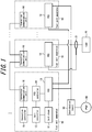
- the fuel cell system 1 includes a plurality of fuel cell apparatuses 10.
- the fuel cell apparatuses 10 connect to each other and perform connected operation.
- Each fuel cell apparatus 10 connects to a load 20 and can supply electric power to the load 20.
- the fuel cell apparatuses 10 and the load 20 connect to a power grid 40 through a distribution board 30.
- the fuel cell apparatus 10 includes a cell stack 11, a cell controller 12, and a power conditioning system (PCS) 13.
- the PCS 13 is also known as a power control apparatus.
- the fuel cell apparatus 10 further includes a PCS controller 14, a connection controller 15, and a connection communication unit 16.
- the connection controller 15 and the connection communication unit 16 are provided so as to be included in the fuel cell apparatus 10.
- the connection controller 15 and the connection communication unit 16 may each be provided outside of the fuel cell apparatus 10 as a separate control apparatus and connect to the fuel cell apparatus 10.
- the cell controller 12 and the connection controller 15 are also collectively referred to as a controller.
- the connection communication unit 16 is also referred to as a communication unit.
- the cell stack 11 is a fuel cell.
- the cell stack 11 may, for example, be a polymer electrolyte fuel cell (PEFC) or a solid oxide fuel cell (SOFC).
- PEFC polymer electrolyte fuel cell
- SOFC solid oxide fuel cell
- the cell stack 11 is not limited to these examples and may be a different fuel cell.
- the cell stack 11 connects to the cell controller 12.
- the cell controller 12 controls the power generation by the cell stack 11.
- the cell stack 11 connects to the PCS 13.
- the PCS 13 converts the DC power generated by the cell stack 11 to AC power and supplies the AC power to the load 20.
- the PCS 13 is also referred to as a power conversion apparatus.
- the PCS 13 connects to the PCS controller 14.
- the PCS controller 14 also connects to the cell controller 12.
- the PCS controller 14 cooperates with the cell controller 12 to control AC power output of the PCS 13.
- the cell controller 12 further connects to the connection controller 15.
- the connection controller 15 connects to the connection communication unit 16.
- the connection communication unit 16 communicably connects to the connection communication units 16 of other fuel cell apparatuses 10.
- the connection communication unit 16 transmits control information pertaining to the respective apparatus and acquires control information pertaining to the other fuel cell apparatuses 10.
- the cell controller 12 cooperates with the directly connected connection controller 15 or with the connection controller 15 of another fuel cell apparatus 10 connected via the connection communication unit 16.
- the cell controller 12 controls the power generation by the cell stack 11 on the basis of acquired control information.
- the connection controller 15 can also be said to control the power generation by the cell stack 11 through the cell controller 12.
- the control information includes a signal or information exchanged between fuel cell apparatuses 10 performing connected operation.
- the control information includes a status request, response information, an instruction to control power generation, or the like.
- connection communication units 16 of the fuel cell apparatuses 10 serially connect to each other in accordance with the RS-485 standard, for example.
- the connection communication units 16 of the fuel cell apparatuses 10 may, for example, connect in a daisy chain.
- the connection between the connection communication units 16 is not limited to these examples.
- the connection communication units 16 may connect to a bus line.
- connection communication units 16 When the connection communication units 16 are connected in a daisy chain, the signal transmitted from one fuel cell apparatus 10 is acquired by all of the other fuel cell apparatuses 10 connected in the daisy chain. In other words, the connection communication units 16 communicate with each other as if they were connected to a bus line. In this case, information designating the fuel cell apparatus 10 that is the recipient is included in the signal. One fuel cell apparatus 10 or all of the other fuel cell apparatuses 10 may be designated as the recipient.
- the transmission of a signal or information from the connection communication unit 16 to the connection communication unit 16 of another fuel cell apparatus 10 connected in the daisy chain is also referred to as a broadcast.
- a current sensor 21 is provided in the power line that supplies electric power to the load 20.
- the current sensor 21 measures the current of the load 20.
- the current sensor 21 connects to the PCS 13 of each fuel cell apparatus 10.
- the PCS 13 can acquire the power consumption of the load 20 by acquiring the measured value of the current sensor 21.
- one fuel cell apparatus 10 When the fuel cell apparatuses 10 perform connected operation, one fuel cell apparatus 10 is set as a master apparatus. The other fuel cell apparatuses 10 are set as slave apparatuses. From the perspective of a particular fuel cell apparatus 10, one fuel cell apparatus 10 from among the particular fuel cell apparatus 10 and the other fuel cell apparatuses 10 is set as the master apparatus. The remaining fuel cell apparatuses 10, including the particular fuel cell apparatus 10, are set as slave apparatuses. In the present embodiment, four fuel cell apparatuses 10 perform connected operation. The number of fuel cell apparatuses 10 performing connected operation is not limited to four and may be either less or greater than four. When four fuel cell apparatuses 10 are performing connected operation, the fuel cell apparatuses 10 are set each to correspond to one of a master apparatus and slave apparatuses A, B, and C.
- the slave apparatus A can be distinguished as a first slave apparatus.
- the slave apparatuses B and C can be distinguished as second slave apparatuses.
- the slave apparatus distinguished as the first slave apparatus is not limited to the slave apparatus A and may instead be the slave apparatus B or the slave apparatus C.
- the slave apparatus A may be distinguished as the second slave apparatus.
- the indication of slave apparatuses "A”, “B”, and “C” and the indication of "first” and “second” slave apparatuses are for distinguishing the slave apparatuses by identifiers.
- the identifiers "A”, “B”, and “C", along with "first” and “second”, may be interchanged or replaced with other identifiers.
- connection controller 15 of the master apparatus transmits a status request to the slave apparatus A (step S11a).
- the transmission of the status request is performed through the connection communication unit 16.
- the master apparatus enters a response waiting state (step S12a).
- the slave apparatus A Upon receiving the status request from the master apparatus, the slave apparatus A generates response information indicating the state of the fuel cell apparatus 10 set as the slave apparatus A (step S13a).
- the generated power, operating time, degradation information, the number of times maintenance has been performed, the number of times an abnormality has occurred, or the like for the fuel cell apparatus 10 are included in the response information.
- the slave apparatus A transmits the generated response information to the master apparatus (step S14a).
- the transmission of the response information is performed through the connection communication unit 16.
- the master apparatus successfully acquires the response information from the slave apparatus A while waiting for the response in step S12a (when not timing out)
- the master apparatus judges that response information could be acquired normally from the slave apparatus A.
- the master apparatus transmits a status request to each of the slave apparatuses B and C as well.
- the master apparatus acquires the response information from the slave apparatuses B and C (steps S11b to S14b and steps S11c to S14c).
- the connection controller 15 of the master apparatus calculates the total generated power as the sum of the generated power of each fuel cell apparatus 10.
- the connection controller 15 of the master apparatus acquires the power consumption of the load 20 through the PCS 13 and determines the generated power of each fuel cell apparatus 10 on the basis of a comparison with the total generated power.
- the connection communication unit 16 of the master apparatus broadcasts an instruction to control power generation to each fuel cell apparatus 10.
- the connection communication unit 16 of the master apparatus may transmit the control instruction for controlling the power generation of the slave apparatus to each slave apparatus with a sequence similar to the transmission of the status request.
- the control instruction may be transmitted by being included in the status request.
- the master apparatus acquires response information indicating the state of the slave apparatuses and transmits control instructions to the slave apparatuses.
- the master apparatus acquires response information indicating the state of the slave apparatuses and transmits control instructions to the slave apparatuses.
- step S21 when a problem occurs in the master apparatus, the master apparatus stops operating (step S21).
- the slave apparatus A When the slave apparatus A cannot acquire a status request from the master apparatus after at least a predetermined period has elapsed, the slave apparatus A performs a timeout process. The slave apparatus A judges that a problem has occurred in the master apparatus causing loss of functionality in the master apparatus (step S22).
- the slave apparatus A broadcasts a master candidacy message to the slave apparatus B and the slave apparatus C (steps S23b and S23c).
- the master candidacy message is a message indicating that an apparatus is offering itself as a candidate to be the new master apparatus to assume the functionality of the master apparatus by proxy.
- the slave apparatus A performs a process to add itself to a candidate list as a candidate apparatus (step S24a).
- the slave apparatus B and slave apparatus C can detect that the master apparatus has lost functionality by acquiring the master candidacy message from the slave apparatus A.
- the slave apparatus B and the slave apparatus C suspend acquisition of the status request from the master apparatus (steps S24b and S24c).
- the slave apparatus B and the slave apparatus C further perform a process to add the slave apparatus A to the candidate list as a candidate apparatus.
- the slave apparatus B When the slave apparatus B detects that the master apparatus has lost functionality, then like the slave apparatus A, the slave apparatus B broadcasts a master candidacy message to the slave apparatus A and the slave apparatus C (steps S25a and S25c). The slave apparatus B performs a process to add itself to the candidate list as a candidate apparatus (step S26b). After acquiring the master candidacy message from the slave apparatus B, the slave apparatus A and the slave apparatus C perform a process to add the slave apparatus B to the candidate list as a candidate apparatus (steps S26a and S26c).
- the slave apparatus C when the slave apparatus C detects that the master apparatus has lost functionality, the slave apparatus C broadcasts a master candidacy message to the slave apparatus A and the slave apparatus B (steps S27a and S27b). The slave apparatus C performs a process to add itself to the candidate list as a candidate apparatus (step S28c). After acquiring the master candidacy message from the slave apparatus C, the slave apparatus A and the slave apparatus B perform a process to add the slave apparatus C to the candidate list as a candidate apparatus (steps S28a and S28b).
- the master candidacy message is broadcast to all of the slave apparatuses.
- the candidate list acquired by each slave apparatus is the same.
- Information indicating the state of each slave apparatus may be included in the master candidacy message. By including information indicating the state of each slave apparatus in the master candidacy message, the state of the respective apparatus and the state of other candidate apparatuses can be shared with the other candidate apparatuses when determining the master apparatus.
- the slave apparatus A, slave apparatus B, and slave apparatus C each determine the new master apparatus from among the candidate apparatuses (steps S31a to S31c).
- Each slave apparatus determines the new master apparatus on the basis of a shared algorithm.
- Each slave apparatus can uniquely determine the new master apparatus by sharing the state of the respective apparatus and the state of the other candidate apparatuses with the other candidate apparatuses.
- at least one of the slave apparatuses A, B, and C may be the slave apparatus that determines the master apparatus.
- the algorithm for determining the master apparatus may, for example, be a comparison of the utilization rate of each fuel cell apparatus 10 as calculated on the basis of information indicating the state of each fuel cell apparatus 10.
- the fuel cell apparatus 10 with the highest utilization rate may be determined to be the master apparatus.
- the information indicating the state of the fuel cell apparatus 10 includes a parameter indicating the state of health of the fuel cell apparatus 10, such as the operating time, degree of degradation, the number of times maintenance has been performed, the number of times an abnormality has occurred, or the like for the fuel cell apparatus 10.
- the master apparatus may be determined by how large the manufacturing number of the fuel cell apparatuses 10 is. With this approach, the master apparatus can always be determined uniquely.
- each slave apparatus determines the slave apparatus A to be the new master apparatus.
- at least one of the slave apparatuses A, B, and C may be the slave apparatus that determines the slave apparatus A to be the new master apparatus.
- the slave apparatus A performs a process to transition from the state of being a candidate master apparatus to a state of being determined as the master apparatus (step S32).
- the slave apparatus B and the slave apparatus C perform a process to withdraw their candidacy from the state of being a candidate master apparatus (steps S33b and S33c).
- the slave apparatus A broadcasts a master determination notification, indicating that the slave apparatus A has been determined to be the master apparatus, to the slave apparatus B and the slave apparatus C (steps S34b and S34c).
- the slave apparatus A performs a process to set itself as the master apparatus (step S35a).
- the slave apparatus B and the slave apparatus C After acquiring the master determination notification from the slave apparatus A, the slave apparatus B and the slave apparatus C perform a process to recognize that the slave apparatus A has been set as the master apparatus (step S35b and S35c).
- the fuel cell apparatus 10 that was the slave apparatus A in FIG. 3 and FIG. 4 is newly set as the master apparatus.
- the fuel cell apparatuses 10 that were the slave apparatus B and the slave apparatus C in FIG. 3 and 4 are newly set as the slave apparatus A and the slave apparatus B.
- the labels A, B, and C attached to the slave apparatuses are simply for distinguishing the slave apparatuses and do not signify any order of priority among the slave apparatuses.
- the original slave apparatus B is described as being newly set as the slave apparatus A, but the original slave apparatus B may continue to be set as the slave apparatus B.
- connection controller 15 of the newly set master apparatus transmits a status request to the newly set slave apparatus A (step S41a).
- the transmission of the status request is performed through the connection communication unit 16.
- the master apparatus enters a response waiting state (step S42a).
- the slave apparatus A Upon receiving the status request from the master apparatus, the slave apparatus A generates response information indicating the state of the fuel cell apparatus 10 set as the slave apparatus A (step S43a).
- the slave apparatus A transmits the generated response information to the master apparatus (step S44a).
- the transmission of the response information is performed through the connection communication unit 16.
- the master apparatus judges that normal acquisition of the response information from the slave apparatus A is successful.
- the case of successfully acquiring the response information from the slave apparatus A while waiting for the response in step S42a can also be referred to as not timing out.
- the master apparatus transmits a status request to the newly set slave apparatus B as well and acquires response information from the slave apparatus B (steps S41b to S44b).
- the fuel cell apparatus 10 that was the master apparatus in FIG. 3 and FIG. 4 receives maintenance or repair while connected operation is being performed by the newly set master apparatus and then returns to a normal state and resumes operation. At this time, this fuel cell apparatus 10 is newly set as the slave apparatus C.
- the master apparatus transmits a status request to the newly set slave apparatus C as well, as for the slave apparatus A and the slave apparatus B, and acquires response information from the slave apparatus C (steps S41c to S44c).
- the present disclosure has been described focusing on apparatuses, the present disclosure may also be embodied as a method or program executed by a processor provided in an apparatus, or as a recording medium on which a program is recorded. Such embodiments are also to be understood as included in the scope of the present disclosure.
Applications Claiming Priority (2)
| Application Number | Priority Date | Filing Date | Title |
|---|---|---|---|
| JP2015213386 | 2015-10-29 | ||
| PCT/JP2016/004746 WO2017073071A1 (fr) | 2015-10-29 | 2016-10-28 | Dispositif de pile à combustible, système de pile à combustible, procédé de commande de système de pile à combustible, et dispositif de commande |
Publications (3)
| Publication Number | Publication Date |
|---|---|
| EP3370291A1 true EP3370291A1 (fr) | 2018-09-05 |
| EP3370291A4 EP3370291A4 (fr) | 2019-07-24 |
| EP3370291B1 EP3370291B1 (fr) | 2020-12-02 |
Family
ID=58630065
Family Applications (1)
| Application Number | Title | Priority Date | Filing Date |
|---|---|---|---|
| EP16859309.3A Active EP3370291B1 (fr) | 2015-10-29 | 2016-10-28 | Dispositif de pile à combustible, système de pile à combustible, procédé de commande de système de pile à combustible, et dispositif de commande |
Country Status (4)
| Country | Link |
|---|---|
| US (1) | US10741860B2 (fr) |
| EP (1) | EP3370291B1 (fr) |
| JP (1) | JP6561132B2 (fr) |
| WO (1) | WO2017073071A1 (fr) |
Families Citing this family (5)
| Publication number | Priority date | Publication date | Assignee | Title |
|---|---|---|---|---|
| CN108963353A (zh) * | 2017-05-26 | 2018-12-07 | 宁德时代新能源科技股份有限公司 | 电池包的主从识别方法及装置 |
| KR101989388B1 (ko) * | 2018-12-14 | 2019-06-14 | (주)에프씨아이 | 연료전지 제어 시스템 |
| JP7297703B2 (ja) * | 2019-05-31 | 2023-06-26 | 株式会社東芝 | 燃料電池システムおよびその運転方法 |
| CN112018413A (zh) * | 2019-05-31 | 2020-12-01 | 株式会社东芝 | 燃料电池系统及其运转方法 |
| CN110556553B (zh) * | 2019-08-29 | 2021-10-15 | 武汉中极氢能产业创新中心有限公司 | 一种安全控制方法、燃料电池测试装置和存储介质 |
Family Cites Families (6)
| Publication number | Priority date | Publication date | Assignee | Title |
|---|---|---|---|---|
| JP3378394B2 (ja) | 1994-12-19 | 2003-02-17 | 東芝システムテクノロジー株式会社 | 燃料電池発電プラントの並列運転装置 |
| JPH0916427A (ja) * | 1995-06-29 | 1997-01-17 | Fujitsu Ltd | 二重化制御方法並びにそのためのマスタ制御装置及びスレーブ制御装置 |
| JP3764056B2 (ja) | 2001-02-16 | 2006-04-05 | ヤンマー株式会社 | パワーコンディショナの運転制御装置とその運転制御方法 |
| JP2004178877A (ja) * | 2002-11-26 | 2004-06-24 | Ebara Ballard Corp | 燃料電池システム |
| US20060134479A1 (en) | 2004-12-22 | 2006-06-22 | Luhui Hu | Controlling a fuel cell system |
| JP5158600B2 (ja) | 2008-10-15 | 2013-03-06 | 国立大学法人名古屋大学 | 通信装置、通信システム及び通信方法 |
-
2016
- 2016-10-28 JP JP2017547629A patent/JP6561132B2/ja active Active
- 2016-10-28 EP EP16859309.3A patent/EP3370291B1/fr active Active
- 2016-10-28 WO PCT/JP2016/004746 patent/WO2017073071A1/fr active Application Filing
- 2016-10-28 US US15/771,583 patent/US10741860B2/en active Active
Also Published As
| Publication number | Publication date |
|---|---|
| JP6561132B2 (ja) | 2019-08-14 |
| US20180323454A1 (en) | 2018-11-08 |
| JPWO2017073071A1 (ja) | 2018-08-02 |
| EP3370291A4 (fr) | 2019-07-24 |
| WO2017073071A1 (fr) | 2017-05-04 |
| EP3370291B1 (fr) | 2020-12-02 |
| US10741860B2 (en) | 2020-08-11 |
Similar Documents
| Publication | Publication Date | Title |
|---|---|---|
| EP3370291B1 (fr) | Dispositif de pile à combustible, système de pile à combustible, procédé de commande de système de pile à combustible, et dispositif de commande | |
| US7831860B2 (en) | System and method for testing redundancy and hot-swapping capability of a redundant power supply | |
| US9223394B2 (en) | Rack and power control method thereof | |
| JP2010066824A (ja) | 給電システム及び給電方法 | |
| JP4732403B2 (ja) | 蓄電池システムの制御方法及び制御回路 | |
| JP2015530863A (ja) | エネルギー貯蔵システムおよびモジュール通信 | |
| US20150006943A1 (en) | Information processing device, improper connection detection method, and computer readable recording medium having stored therein improper connection detection program | |
| US10942555B2 (en) | Power supplying method for computer system | |
| JP2008306851A (ja) | 非常用電源設備管理システム、非常用電源設備管理方法、非常用電源設備管理プログラム | |
| EP2693617B1 (fr) | Appareil d'alimentation électrique, appareil de traitement, système de traitement d'informations et procédé de commande d'alimentation | |
| JP2014204447A (ja) | 電源管理システム及び電源切替制御装置 | |
| JP2013077520A (ja) | 蓄電池装置、蓄電池装置の制御方法及び制御プログラム | |
| US11093014B2 (en) | Method for monitoring, control and graceful shutdown of control and/or computer units | |
| JP2012137887A (ja) | コンピュータシステム、及び電源モジュールの運用方法 | |
| US11733762B2 (en) | Method to allow for higher usable power capacity in a redundant power configuration | |
| CN104349001A (zh) | 信息处理装置及其控制方法 | |
| US8566630B2 (en) | Apparatus, methods and computer program products supporting automatic network identification for power supplies | |
| JP2005287174A (ja) | 無停電電源装置 | |
| CN109814697B (zh) | 用于计算机系统的电力供应方法 | |
| JP2012070307A (ja) | 多重化システム及び多重化システムの制御方法 | |
| JP6036229B2 (ja) | バッテリ制御装置、バッテリ制御方法及びプログラム | |
| JP2011227786A (ja) | マイクロコンピュータ制御システム、並びにそれを用いた充電装置および太陽光電源システム | |
| EP3916518B1 (fr) | Combinaison d'alimentation comportant des alimentations hétérogènes | |
| JP2014050256A (ja) | 工場エネルギー管理システム、電力管理装置および工場エネルギー管理方法 | |
| EP3916519B1 (fr) | Procédé et circuit de commande pour contrôler l'alimentation électrique à un ou plusieurs serveurs |
Legal Events
| Date | Code | Title | Description |
|---|---|---|---|
| STAA | Information on the status of an ep patent application or granted ep patent |
Free format text: STATUS: THE INTERNATIONAL PUBLICATION HAS BEEN MADE |
|
| PUAI | Public reference made under article 153(3) epc to a published international application that has entered the european phase |
Free format text: ORIGINAL CODE: 0009012 |
|
| STAA | Information on the status of an ep patent application or granted ep patent |
Free format text: STATUS: REQUEST FOR EXAMINATION WAS MADE |
|
| 17P | Request for examination filed |
Effective date: 20180427 |
|
| AK | Designated contracting states |
Kind code of ref document: A1 Designated state(s): AL AT BE BG CH CY CZ DE DK EE ES FI FR GB GR HR HU IE IS IT LI LT LU LV MC MK MT NL NO PL PT RO RS SE SI SK SM TR |
|
| AX | Request for extension of the european patent |
Extension state: BA ME |
|
| DAV | Request for validation of the european patent (deleted) | ||
| DAX | Request for extension of the european patent (deleted) | ||
| A4 | Supplementary search report drawn up and despatched |
Effective date: 20190625 |
|
| RIC1 | Information provided on ipc code assigned before grant |
Ipc: H02J 1/00 20060101ALI20190618BHEP Ipc: H01M 8/04992 20160101ALI20190618BHEP Ipc: H01M 8/04664 20160101ALI20190618BHEP Ipc: H02J 3/46 20060101ALI20190618BHEP Ipc: H01M 8/04858 20160101AFI20190618BHEP Ipc: H02J 3/38 20060101ALI20190618BHEP |
|
| GRAP | Despatch of communication of intention to grant a patent |
Free format text: ORIGINAL CODE: EPIDOSNIGR1 |
|
| STAA | Information on the status of an ep patent application or granted ep patent |
Free format text: STATUS: GRANT OF PATENT IS INTENDED |
|
| INTG | Intention to grant announced |
Effective date: 20200623 |
|
| GRAS | Grant fee paid |
Free format text: ORIGINAL CODE: EPIDOSNIGR3 |
|
| GRAA | (expected) grant |
Free format text: ORIGINAL CODE: 0009210 |
|
| STAA | Information on the status of an ep patent application or granted ep patent |
Free format text: STATUS: THE PATENT HAS BEEN GRANTED |
|
| AK | Designated contracting states |
Kind code of ref document: B1 Designated state(s): AL AT BE BG CH CY CZ DE DK EE ES FI FR GB GR HR HU IE IS IT LI LT LU LV MC MK MT NL NO PL PT RO RS SE SI SK SM TR |
|
| REG | Reference to a national code |
Ref country code: GB Ref legal event code: FG4D |
|
| REG | Reference to a national code |
Ref country code: AT Ref legal event code: REF Ref document number: 1341913 Country of ref document: AT Kind code of ref document: T Effective date: 20201215 Ref country code: CH Ref legal event code: EP |
|
| REG | Reference to a national code |
Ref country code: IE Ref legal event code: FG4D |
|
| REG | Reference to a national code |
Ref country code: DE Ref legal event code: R096 Ref document number: 602016049222 Country of ref document: DE |
|
| PG25 | Lapsed in a contracting state [announced via postgrant information from national office to epo] |
Ref country code: NO Free format text: LAPSE BECAUSE OF FAILURE TO SUBMIT A TRANSLATION OF THE DESCRIPTION OR TO PAY THE FEE WITHIN THE PRESCRIBED TIME-LIMIT Effective date: 20210302 Ref country code: RS Free format text: LAPSE BECAUSE OF FAILURE TO SUBMIT A TRANSLATION OF THE DESCRIPTION OR TO PAY THE FEE WITHIN THE PRESCRIBED TIME-LIMIT Effective date: 20201202 Ref country code: GR Free format text: LAPSE BECAUSE OF FAILURE TO SUBMIT A TRANSLATION OF THE DESCRIPTION OR TO PAY THE FEE WITHIN THE PRESCRIBED TIME-LIMIT Effective date: 20210303 Ref country code: FI Free format text: LAPSE BECAUSE OF FAILURE TO SUBMIT A TRANSLATION OF THE DESCRIPTION OR TO PAY THE FEE WITHIN THE PRESCRIBED TIME-LIMIT Effective date: 20201202 |
|
| REG | Reference to a national code |
Ref country code: NL Ref legal event code: MP Effective date: 20201202 |
|
| REG | Reference to a national code |
Ref country code: AT Ref legal event code: MK05 Ref document number: 1341913 Country of ref document: AT Kind code of ref document: T Effective date: 20201202 |
|
| PG25 | Lapsed in a contracting state [announced via postgrant information from national office to epo] |
Ref country code: PL Free format text: LAPSE BECAUSE OF FAILURE TO SUBMIT A TRANSLATION OF THE DESCRIPTION OR TO PAY THE FEE WITHIN THE PRESCRIBED TIME-LIMIT Effective date: 20201202 Ref country code: LV Free format text: LAPSE BECAUSE OF FAILURE TO SUBMIT A TRANSLATION OF THE DESCRIPTION OR TO PAY THE FEE WITHIN THE PRESCRIBED TIME-LIMIT Effective date: 20201202 Ref country code: BG Free format text: LAPSE BECAUSE OF FAILURE TO SUBMIT A TRANSLATION OF THE DESCRIPTION OR TO PAY THE FEE WITHIN THE PRESCRIBED TIME-LIMIT Effective date: 20210302 Ref country code: SE Free format text: LAPSE BECAUSE OF FAILURE TO SUBMIT A TRANSLATION OF THE DESCRIPTION OR TO PAY THE FEE WITHIN THE PRESCRIBED TIME-LIMIT Effective date: 20201202 |
|
| PG25 | Lapsed in a contracting state [announced via postgrant information from national office to epo] |
Ref country code: NL Free format text: LAPSE BECAUSE OF FAILURE TO SUBMIT A TRANSLATION OF THE DESCRIPTION OR TO PAY THE FEE WITHIN THE PRESCRIBED TIME-LIMIT Effective date: 20201202 Ref country code: HR Free format text: LAPSE BECAUSE OF FAILURE TO SUBMIT A TRANSLATION OF THE DESCRIPTION OR TO PAY THE FEE WITHIN THE PRESCRIBED TIME-LIMIT Effective date: 20201202 |
|
| REG | Reference to a national code |
Ref country code: LT Ref legal event code: MG9D |
|
| PG25 | Lapsed in a contracting state [announced via postgrant information from national office to epo] |
Ref country code: PT Free format text: LAPSE BECAUSE OF FAILURE TO SUBMIT A TRANSLATION OF THE DESCRIPTION OR TO PAY THE FEE WITHIN THE PRESCRIBED TIME-LIMIT Effective date: 20210405 Ref country code: RO Free format text: LAPSE BECAUSE OF FAILURE TO SUBMIT A TRANSLATION OF THE DESCRIPTION OR TO PAY THE FEE WITHIN THE PRESCRIBED TIME-LIMIT Effective date: 20201202 Ref country code: SK Free format text: LAPSE BECAUSE OF FAILURE TO SUBMIT A TRANSLATION OF THE DESCRIPTION OR TO PAY THE FEE WITHIN THE PRESCRIBED TIME-LIMIT Effective date: 20201202 Ref country code: LT Free format text: LAPSE BECAUSE OF FAILURE TO SUBMIT A TRANSLATION OF THE DESCRIPTION OR TO PAY THE FEE WITHIN THE PRESCRIBED TIME-LIMIT Effective date: 20201202 Ref country code: SM Free format text: LAPSE BECAUSE OF FAILURE TO SUBMIT A TRANSLATION OF THE DESCRIPTION OR TO PAY THE FEE WITHIN THE PRESCRIBED TIME-LIMIT Effective date: 20201202 Ref country code: CZ Free format text: LAPSE BECAUSE OF FAILURE TO SUBMIT A TRANSLATION OF THE DESCRIPTION OR TO PAY THE FEE WITHIN THE PRESCRIBED TIME-LIMIT Effective date: 20201202 Ref country code: EE Free format text: LAPSE BECAUSE OF FAILURE TO SUBMIT A TRANSLATION OF THE DESCRIPTION OR TO PAY THE FEE WITHIN THE PRESCRIBED TIME-LIMIT Effective date: 20201202 |
|
| PG25 | Lapsed in a contracting state [announced via postgrant information from national office to epo] |
Ref country code: AT Free format text: LAPSE BECAUSE OF FAILURE TO SUBMIT A TRANSLATION OF THE DESCRIPTION OR TO PAY THE FEE WITHIN THE PRESCRIBED TIME-LIMIT Effective date: 20201202 |
|
| REG | Reference to a national code |
Ref country code: DE Ref legal event code: R097 Ref document number: 602016049222 Country of ref document: DE |
|
| PG25 | Lapsed in a contracting state [announced via postgrant information from national office to epo] |
Ref country code: IS Free format text: LAPSE BECAUSE OF FAILURE TO SUBMIT A TRANSLATION OF THE DESCRIPTION OR TO PAY THE FEE WITHIN THE PRESCRIBED TIME-LIMIT Effective date: 20210402 |
|
| PLBE | No opposition filed within time limit |
Free format text: ORIGINAL CODE: 0009261 |
|
| STAA | Information on the status of an ep patent application or granted ep patent |
Free format text: STATUS: NO OPPOSITION FILED WITHIN TIME LIMIT |
|
| PG25 | Lapsed in a contracting state [announced via postgrant information from national office to epo] |
Ref country code: IT Free format text: LAPSE BECAUSE OF FAILURE TO SUBMIT A TRANSLATION OF THE DESCRIPTION OR TO PAY THE FEE WITHIN THE PRESCRIBED TIME-LIMIT Effective date: 20201202 Ref country code: AL Free format text: LAPSE BECAUSE OF FAILURE TO SUBMIT A TRANSLATION OF THE DESCRIPTION OR TO PAY THE FEE WITHIN THE PRESCRIBED TIME-LIMIT Effective date: 20201202 |
|
| 26N | No opposition filed |
Effective date: 20210903 |
|
| PG25 | Lapsed in a contracting state [announced via postgrant information from national office to epo] |
Ref country code: DK Free format text: LAPSE BECAUSE OF FAILURE TO SUBMIT A TRANSLATION OF THE DESCRIPTION OR TO PAY THE FEE WITHIN THE PRESCRIBED TIME-LIMIT Effective date: 20201202 Ref country code: SI Free format text: LAPSE BECAUSE OF FAILURE TO SUBMIT A TRANSLATION OF THE DESCRIPTION OR TO PAY THE FEE WITHIN THE PRESCRIBED TIME-LIMIT Effective date: 20201202 |
|
| PG25 | Lapsed in a contracting state [announced via postgrant information from national office to epo] |
Ref country code: ES Free format text: LAPSE BECAUSE OF FAILURE TO SUBMIT A TRANSLATION OF THE DESCRIPTION OR TO PAY THE FEE WITHIN THE PRESCRIBED TIME-LIMIT Effective date: 20201202 |
|
| REG | Reference to a national code |
Ref country code: CH Ref legal event code: PL |
|
| PG25 | Lapsed in a contracting state [announced via postgrant information from national office to epo] |
Ref country code: IS Free format text: LAPSE BECAUSE OF FAILURE TO SUBMIT A TRANSLATION OF THE DESCRIPTION OR TO PAY THE FEE WITHIN THE PRESCRIBED TIME-LIMIT Effective date: 20210402 |
|
| REG | Reference to a national code |
Ref country code: BE Ref legal event code: MM Effective date: 20211031 |
|
| GBPC | Gb: european patent ceased through non-payment of renewal fee |
Effective date: 20211028 |
|
| PG25 | Lapsed in a contracting state [announced via postgrant information from national office to epo] |
Ref country code: MC Free format text: LAPSE BECAUSE OF FAILURE TO SUBMIT A TRANSLATION OF THE DESCRIPTION OR TO PAY THE FEE WITHIN THE PRESCRIBED TIME-LIMIT Effective date: 20201202 |
|
| PG25 | Lapsed in a contracting state [announced via postgrant information from national office to epo] |
Ref country code: LU Free format text: LAPSE BECAUSE OF NON-PAYMENT OF DUE FEES Effective date: 20211028 Ref country code: GB Free format text: LAPSE BECAUSE OF NON-PAYMENT OF DUE FEES Effective date: 20211028 Ref country code: BE Free format text: LAPSE BECAUSE OF NON-PAYMENT OF DUE FEES Effective date: 20211031 |
|
| PG25 | Lapsed in a contracting state [announced via postgrant information from national office to epo] |
Ref country code: LI Free format text: LAPSE BECAUSE OF NON-PAYMENT OF DUE FEES Effective date: 20211031 Ref country code: CH Free format text: LAPSE BECAUSE OF NON-PAYMENT OF DUE FEES Effective date: 20211031 |
|
| PG25 | Lapsed in a contracting state [announced via postgrant information from national office to epo] |
Ref country code: FR Free format text: LAPSE BECAUSE OF NON-PAYMENT OF DUE FEES Effective date: 20211031 |
|
| PG25 | Lapsed in a contracting state [announced via postgrant information from national office to epo] |
Ref country code: IE Free format text: LAPSE BECAUSE OF NON-PAYMENT OF DUE FEES Effective date: 20211028 |
|
| PG25 | Lapsed in a contracting state [announced via postgrant information from national office to epo] |
Ref country code: HU Free format text: LAPSE BECAUSE OF FAILURE TO SUBMIT A TRANSLATION OF THE DESCRIPTION OR TO PAY THE FEE WITHIN THE PRESCRIBED TIME-LIMIT; INVALID AB INITIO Effective date: 20161028 |
|
| P01 | Opt-out of the competence of the unified patent court (upc) registered |
Effective date: 20230508 |
|
| PG25 | Lapsed in a contracting state [announced via postgrant information from national office to epo] |
Ref country code: CY Free format text: LAPSE BECAUSE OF FAILURE TO SUBMIT A TRANSLATION OF THE DESCRIPTION OR TO PAY THE FEE WITHIN THE PRESCRIBED TIME-LIMIT Effective date: 20201202 |
|
| PGFP | Annual fee paid to national office [announced via postgrant information from national office to epo] |
Ref country code: DE Payment date: 20230906 Year of fee payment: 8 |