EP3369937B1 - Verfahren zur herstellung eines laufrads - Google Patents
Verfahren zur herstellung eines laufrads Download PDFInfo
- Publication number
- EP3369937B1 EP3369937B1 EP16859730.0A EP16859730A EP3369937B1 EP 3369937 B1 EP3369937 B1 EP 3369937B1 EP 16859730 A EP16859730 A EP 16859730A EP 3369937 B1 EP3369937 B1 EP 3369937B1
- Authority
- EP
- European Patent Office
- Prior art keywords
- hub
- blades
- core
- cover
- impeller
- Prior art date
- Legal status (The legal status is an assumption and is not a legal conclusion. Google has not performed a legal analysis and makes no representation as to the accuracy of the status listed.)
- Active
Links
Images








Classifications
-
- F—MECHANICAL ENGINEERING; LIGHTING; HEATING; WEAPONS; BLASTING
- F04—POSITIVE - DISPLACEMENT MACHINES FOR LIQUIDS; PUMPS FOR LIQUIDS OR ELASTIC FLUIDS
- F04D—NON-POSITIVE-DISPLACEMENT PUMPS
- F04D29/00—Details, component parts, or accessories
- F04D29/18—Rotors
- F04D29/22—Rotors specially for centrifugal pumps
-
- B—PERFORMING OPERATIONS; TRANSPORTING
- B23—MACHINE TOOLS; METAL-WORKING NOT OTHERWISE PROVIDED FOR
- B23K—SOLDERING OR UNSOLDERING; WELDING; CLADDING OR PLATING BY SOLDERING OR WELDING; CUTTING BY APPLYING HEAT LOCALLY, e.g. FLAME CUTTING; WORKING BY LASER BEAM
- B23K9/00—Arc welding or cutting
- B23K9/02—Seam welding; Backing means; Inserts
-
- B—PERFORMING OPERATIONS; TRANSPORTING
- B23—MACHINE TOOLS; METAL-WORKING NOT OTHERWISE PROVIDED FOR
- B23K—SOLDERING OR UNSOLDERING; WELDING; CLADDING OR PLATING BY SOLDERING OR WELDING; CUTTING BY APPLYING HEAT LOCALLY, e.g. FLAME CUTTING; WORKING BY LASER BEAM
- B23K9/00—Arc welding or cutting
- B23K9/0026—Arc welding or cutting specially adapted for particular articles or work
-
- B—PERFORMING OPERATIONS; TRANSPORTING
- B23—MACHINE TOOLS; METAL-WORKING NOT OTHERWISE PROVIDED FOR
- B23K—SOLDERING OR UNSOLDERING; WELDING; CLADDING OR PLATING BY SOLDERING OR WELDING; CUTTING BY APPLYING HEAT LOCALLY, e.g. FLAME CUTTING; WORKING BY LASER BEAM
- B23K9/00—Arc welding or cutting
- B23K9/02—Seam welding; Backing means; Inserts
- B23K9/038—Seam welding; Backing means; Inserts using moulding means
-
- B—PERFORMING OPERATIONS; TRANSPORTING
- B23—MACHINE TOOLS; METAL-WORKING NOT OTHERWISE PROVIDED FOR
- B23K—SOLDERING OR UNSOLDERING; WELDING; CLADDING OR PLATING BY SOLDERING OR WELDING; CUTTING BY APPLYING HEAT LOCALLY, e.g. FLAME CUTTING; WORKING BY LASER BEAM
- B23K9/00—Arc welding or cutting
- B23K9/16—Arc welding or cutting making use of shielding gas
-
- F—MECHANICAL ENGINEERING; LIGHTING; HEATING; WEAPONS; BLASTING
- F01—MACHINES OR ENGINES IN GENERAL; ENGINE PLANTS IN GENERAL; STEAM ENGINES
- F01D—NON-POSITIVE DISPLACEMENT MACHINES OR ENGINES, e.g. STEAM TURBINES
- F01D5/00—Blades; Blade-carrying members; Heating, heat-insulating, cooling or antivibration means on the blades or the members
- F01D5/02—Blade-carrying members, e.g. rotors
- F01D5/04—Blade-carrying members, e.g. rotors for radial-flow machines or engines
-
- F—MECHANICAL ENGINEERING; LIGHTING; HEATING; WEAPONS; BLASTING
- F04—POSITIVE - DISPLACEMENT MACHINES FOR LIQUIDS; PUMPS FOR LIQUIDS OR ELASTIC FLUIDS
- F04D—NON-POSITIVE-DISPLACEMENT PUMPS
- F04D29/00—Details, component parts, or accessories
- F04D29/02—Selection of particular materials
- F04D29/023—Selection of particular materials especially adapted for elastic fluid pumps
-
- F—MECHANICAL ENGINEERING; LIGHTING; HEATING; WEAPONS; BLASTING
- F04—POSITIVE - DISPLACEMENT MACHINES FOR LIQUIDS; PUMPS FOR LIQUIDS OR ELASTIC FLUIDS
- F04D—NON-POSITIVE-DISPLACEMENT PUMPS
- F04D29/00—Details, component parts, or accessories
- F04D29/02—Selection of particular materials
- F04D29/026—Selection of particular materials especially adapted for liquid pumps
-
- F—MECHANICAL ENGINEERING; LIGHTING; HEATING; WEAPONS; BLASTING
- F04—POSITIVE - DISPLACEMENT MACHINES FOR LIQUIDS; PUMPS FOR LIQUIDS OR ELASTIC FLUIDS
- F04D—NON-POSITIVE-DISPLACEMENT PUMPS
- F04D29/00—Details, component parts, or accessories
- F04D29/26—Rotors specially for elastic fluids
- F04D29/28—Rotors specially for elastic fluids for centrifugal or helico-centrifugal pumps for radial-flow or helico-centrifugal pumps
-
- F—MECHANICAL ENGINEERING; LIGHTING; HEATING; WEAPONS; BLASTING
- F04—POSITIVE - DISPLACEMENT MACHINES FOR LIQUIDS; PUMPS FOR LIQUIDS OR ELASTIC FLUIDS
- F04D—NON-POSITIVE-DISPLACEMENT PUMPS
- F04D29/00—Details, component parts, or accessories
- F04D29/60—Mounting; Assembling; Disassembling
- F04D29/62—Mounting; Assembling; Disassembling of radial or helico-centrifugal pumps
-
- B—PERFORMING OPERATIONS; TRANSPORTING
- B23—MACHINE TOOLS; METAL-WORKING NOT OTHERWISE PROVIDED FOR
- B23K—SOLDERING OR UNSOLDERING; WELDING; CLADDING OR PLATING BY SOLDERING OR WELDING; CUTTING BY APPLYING HEAT LOCALLY, e.g. FLAME CUTTING; WORKING BY LASER BEAM
- B23K2101/00—Articles made by soldering, welding or cutting
- B23K2101/001—Turbines
-
- F—MECHANICAL ENGINEERING; LIGHTING; HEATING; WEAPONS; BLASTING
- F05—INDEXING SCHEMES RELATING TO ENGINES OR PUMPS IN VARIOUS SUBCLASSES OF CLASSES F01-F04
- F05D—INDEXING SCHEME FOR ASPECTS RELATING TO NON-POSITIVE-DISPLACEMENT MACHINES OR ENGINES, GAS-TURBINES OR JET-PROPULSION PLANTS
- F05D2230/00—Manufacture
- F05D2230/10—Manufacture by removing material
-
- F—MECHANICAL ENGINEERING; LIGHTING; HEATING; WEAPONS; BLASTING
- F05—INDEXING SCHEMES RELATING TO ENGINES OR PUMPS IN VARIOUS SUBCLASSES OF CLASSES F01-F04
- F05D—INDEXING SCHEME FOR ASPECTS RELATING TO NON-POSITIVE-DISPLACEMENT MACHINES OR ENGINES, GAS-TURBINES OR JET-PROPULSION PLANTS
- F05D2230/00—Manufacture
- F05D2230/20—Manufacture essentially without removing material
- F05D2230/23—Manufacture essentially without removing material by permanently joining parts together
- F05D2230/232—Manufacture essentially without removing material by permanently joining parts together by welding
-
- F—MECHANICAL ENGINEERING; LIGHTING; HEATING; WEAPONS; BLASTING
- F05—INDEXING SCHEMES RELATING TO ENGINES OR PUMPS IN VARIOUS SUBCLASSES OF CLASSES F01-F04
- F05D—INDEXING SCHEME FOR ASPECTS RELATING TO NON-POSITIVE-DISPLACEMENT MACHINES OR ENGINES, GAS-TURBINES OR JET-PROPULSION PLANTS
- F05D2230/00—Manufacture
- F05D2230/40—Heat treatment
-
- F—MECHANICAL ENGINEERING; LIGHTING; HEATING; WEAPONS; BLASTING
- F05—INDEXING SCHEMES RELATING TO ENGINES OR PUMPS IN VARIOUS SUBCLASSES OF CLASSES F01-F04
- F05D—INDEXING SCHEME FOR ASPECTS RELATING TO NON-POSITIVE-DISPLACEMENT MACHINES OR ENGINES, GAS-TURBINES OR JET-PROPULSION PLANTS
- F05D2240/00—Components
- F05D2240/20—Rotors
- F05D2240/24—Rotors for turbines
Definitions
- the present invention relates to a method of manufacturing an impeller.
- Structures to be manufactured by welding include not only large structures such as ships and bridges, but also precision machines, as exemplified by bodies of automobiles and trains and impellers of rotating machines.
- rotating machines such as pumps, compressors and turbines
- an tip-opening between a hub and a cover has become narrow and the precision requirement has become strict.
- JP S61 262 465 A shows a method for welding a structure having a narrow gap.
- a deformation preventive material consisting of a water soluble material is packed into spaces to be formed as gaps between members before welding the members together. After the welding the structure is immersed in water to dissolve the deformation preventive material.
- JP H01 205 889 A relates to a method for joining an impeller of a centrifugal compressor, etc. to a main plate by performing vacuum diffusion welding
- the present invention has been made in view of the above problem, and has an object to provide a method of manufacturing an impeller that makes it possible to reduce the deformation of the hub or cover due to the welding.
- the method inter alia comprises:
- the core physically restrains the deformation of the hub due to the contractive force at the time of natural cooling after the welding, and therefore, it is possible to manufacture an impeller in which the deformation amount of the hub is small. Accordingly, it is possible to improve yield rate, to significantly improve production efficiency, and to reduce manufacturing cost.
- a method of manufacturing an impeller according to one aspect of the present invention in the above method of manufacturing an impeller, the method further comprising a step of breaking and removing the core, when a temperature of the hub becomes lower than a predetermined temperature after the step of welding the hub and the blades.
- a method of manufacturing an impeller according to one aspect of the present invention in any one of the above method of manufacturing an impeller, wherein the through-holes of the core have shapes similar to the shapes of the blades, and are wider than the blades in circumferential width.
- the cover and the core are coaxially disposed.
- the hub and the cover are coaxially disposed.
- a method of manufacturing an impeller according to one aspect of the present invention in any one of the above method of manufacturing an impeller, wherein the core is formed using a raw material that is used in precision casting.
- a method of manufacturing an impeller according to one aspect of the present invention in any one of the above method of manufacturing an impeller, wherein the cover is a cover that is carved integrally with the blades by machining.
- a method of manufacturing an impeller according to one aspect of the present invention in any one of the above method of manufacturing an impeller, wherein the impeller is an impeller of a rotating machine.
- a method of manufacturing an impeller according to one aspect of the present invention comprising:
- the core physically restrains the deformation of the cover due to the contractive force at the time of natural cooling after the welding, and therefore, it is possible to manufacture an impeller in which the deformation amount of the cover is small. Accordingly, it is possible to improve yield rate, to significantly improve production efficiency, and to reduce manufacturing cost.
- a method of manufacturing an impeller according to 13th aspect of the present invention comprising:
- each of the divided cores has light, and it is possible to avoid the collapse due to its own weight. Further, it is possible to decrease the bending moment that is generated in the divided core when the divided core is held up, and to secure the strength allowing works such as the fabrication of the divided core and welding setup (the assembly of the divided core). Since the divided core has a small size, the deformation amount during hardening treatment is also small, and combined with the division structure, it is possible to improve the workability for mounting (assembling) the divided core to the impeller. Further, even when the divided core becomes unusable due to deformation or damage, one of the divided cores only needs to be replaced because of the division structure, and therefore, the influence on fabrication cost is decreased.
- a method of manufacturing an impeller according to a 16th aspect of the present invention in the method of manufacturing an impeller according to any one of the 13th to 15th aspect, wherein
- the divided cores support the inner circumference side of the cover, and therefore, it is possible to avoid the inner circumference side of the cover provided on the cores from falling down due to the welding.
- a method of manufacturing an impeller according to a 17th aspect of the present invention in the method of manufacturing an impeller according to any one of the 13th to 16th aspect, the method further comprising a step of respectively disposing outer circumference spacers at interspaces of the adjacent blades on outer circumference sides of the divided cores, in the step of disposing the divided cores, wherein in the step of welding the cover and the blades, an inert gas is supplied from an inner circumference side, such that the inert gas flows through a passage that is formed between the hub and the cover.
- the presence of the outer circumference spacers can restrain the inert gas from leaking to the outside. It is possible to make the inert gas reach a penetration bead that is generated at the time of the welding of the blades, and it is possible to avoid the penetration bead from being oxidized.
- a method of manufacturing an impeller according to a 18th aspect of the present invention in the method of manufacturing an impeller according to any one of the 13th to 17th aspect, wherein
- the divided cores can be formed with the same wooded pattern.
- the wooden pattern for molding the divided cores has a small size, it is possible to use a small and inexpensive additive manufacturing device for resin shaping, in the fabrication of the wooded pattern, and it is possible to fabricate a wooden pattern (resin pattern) having a relatively high shape accuracy at low cost in a short time. Therefore, it is possible to make the divided cores at low cost in a short time.
- the additive manufacturing device it is possible to mass-produce the same divided cores, based on the same 3D model.
- a method of manufacturing an impeller according to a 19th aspect of the present invention in the method of manufacturing an impeller according to any one of the 13th to 18th aspect, wherein wherein thicknesses of the divided cores are smaller than heights of the blades with respect to a front surface of the hub, by a predetermined length.
- top surfaces of the blades melt by the welding, and thereby, the blades contract so that the heights become roughly the same as the thicknesses of the divided cores. Therefore, it is possible to prevent unnecessary force from being applied to the divided cores.
- a method of manufacturing an impeller according to one aspect of the present invention comprising:
- each of the divided cores has light, and it is possible to avoid the collapse due to its own weight. Further, it is possible to decrease the bending moment that is generated in the divided core when the divided core is held up, and to secure the strength allowing works such as the fabrication of the divided core and welding setup (the assembly of the divided core). Since the divided core has a small size, the deformation amount during hardening treatment is also small, and combined with the division structure, it is possible to improve the workability for mounting (assembling) the divided core to the impeller. Further, even when the divided core becomes unusable due to deformation or damage, one of the divided cores only needs to be replaced because of the division structure, and therefore, the influence on fabrication cost is decreased.
- the core physically restrains the deformation of the hub due to the contractive force at the time of natural cooling after the welding, and therefore, it is possible to manufacture an impeller in which the deformation amount of the hub is small. Accordingly, it is possible to improve yield rate, to significantly improve production efficiency, and to reduce manufacturing cost.
- Figure 6 is a perspective view of a cover 3 according to the comparative example.
- Figure 7 is a schematic view showing manufacturing steps for the impeller 21 according to the comparative example, using cross sectional views taken from line CC' in Figure 6 .
- Figure 8 is a detail view showing manufacturing steps for the impeller 21 according to the comparative example, using cross sectional views taken from line DD' in Figure 6 .
- Figure 9 is a detail view showing manufacturing steps following Figure 8 .
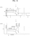
- Figure 10 is a detail view showing manufacturing steps following Figure 9 .
- the cover 3 shown in Figure 6 is obtained by carving the cover 3 integrated with blades 4, from a forging material.
- a plurality of blades 4 is provided on the cover 3.
- Figure 7(A) which is a CC' cross-sectional view of Figure 6
- the blades 4 are provided so as to be roughly perpendicular to the cover 3.
- step 1 of Figure 8 which is a DD' cross-sectional view of Figure 6
- the blades 4 are provided on the cover 3.
- step 2 of Figure 8 a centering fixture 8 made of steel is placed at the center of the cover 3.
- step 3 of Figure 8 and step 4 of Figure 9 the hub 2 is placed on the cover 3.
- grooves 5 for the slot welding of the blades 4 and the hub 2 are provided on a surface on the side opposite to a surface that contacts with the blades 4.
- the shape of the grooves 5 is a similar shape to upper surfaces (bonding surfaces) of the blades 4, and is slightly larger than that of the blades 4.
- the hub 2 is placed such that the horizontal positions of the blades 4 roughly coincide with the horizontal positions of the grooves 5.
- a plurality of holes 9 for welding is provided on the grooves 5.
- an outer circumference portion of the hub 2 and an outer circumference portion of the cover 3 are fixed by a fixture 7.
- the fixture 7 has a zonal plate shape, and by the fixture 7, the outer circumference side of the hub 2 and the outer circumference side of the cover 3 are fixed over the whole circumference.
- a welding material is poured from the holes 9 provided on the grooves 5.
- the hub 2 and the blades 4 are temporarily joined by welding, the fixture 7 and the hub 2 are temporarily joined by welding, and the fixture 7 and the cover 3 are temporarily joined by welding.
- an electric welding is performed along the groove 5.
- the slot welding is performed from the inner circumference side of the groove 5 toward the outer circumference side, at an electric current of 60 A to 190 A.
- the welding material is poured from the holes 9 for welding shown in Figure 7(C) , and the hub 2 and the blades 4 are welded.
- a structure shown in Figure 7(C) is obtained.
- Figure 7(C) in a cross section taken from line CC' in Figure 6 , there is a deformation by which the hub 2 drops to the side of the cover 3 between the blade 4 and the blade 4.
- step 7 of Figure 10 an annealing is performed at 500 to 600°C for about three hours, in order to remove distortion.
- step 8 of Figure 10 a spot fixed by the fixture 7 and the like is eliminated, and a surface processing is performed in accordance with design dimensions. Thereby, the impeller 21 according to the comparative example is completed, and the impeller having a cross section shown in Figure 7(D) is obtained.
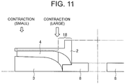
- FIG 11 is a diagram for describing the contraction amount of the impeller 21 according to the comparative example. The welding is performed in a state where the outer circumference side is fixed and the inner circumference side is a free end, and therefore, as shown in Figure 11 , the contraction of the inner circumference side is larger than that of the outer circumference side, so that the deformation of the inner circumference side is larger than that of the outer circumference side.
- a core is interposed between the hub 2 and the cover 3, and the hub 2 is physically restrained from dropping to the side of the cover 3 between the blade 4 and the blade 4.
- the rotating machine is a pump, a turbine, a compressor, or an air blower.
- Figure 1 is a perspective view showing the outline of manufacturing steps for an impeller 1 according to the embodiment.
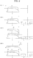
- Figure 2 is a cross-sectional view showing the detail of the manufacturing steps for the impeller 1 according to the embodiment.
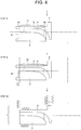
- Figure 3 is a cross-sectional view showing manufacturing steps following Figure 2 .
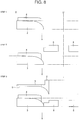
- Figure 4 is a cross-sectional view showing manufacturing steps following Figure 3 .
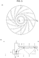
- Figure 5(A) is a top view of an impeller in the state of Figure 1(D) .
- Figure 5(B) is a cross-sectional view taken from line BB' in Figure 5(A) .
- the cover 3 provided with the blades 4 is formed. Specifically, by machining, the cover 3 is carved from a forging material integrally with the blades 4. As shown in Figure 1(A) , the cover 3 has a disk shape. As shown in step 1 of Figure 2 , the cover 3 is placed. Next, as shown in Figure 1(B) and step 2 of Figure 2 , a centering fixture 8 is mounted at the center of the cover 3.
- a core 10 is disposed on the cover 3 such that the core 10 is interposed between the blade 4 and the blade 4.
- the core 10 has a disk shape, and through-holes (slits) 14 conforming to the shapes of the blades 4 are provided on the core 10, such that the blades 4 are fitted in the core 10 when the core 10 is disposed.
- the number of the through-holes 14 provided on the core 10 is the same as the number of the blades 4.
- the specific disposing method is shown as follows.
- the core 10 is disposed by overlaying the core 10 on the cover 3 such that the horizontal positions of the plurality of blades 4 roughly coincide with the horizontal positions of the corresponding through-holes 14.
- the core 10 is disposed such that the central axis of the core 10 roughly coincides with the central axis of the cover 3.
- the through-holes 14 of the core 10 have shapes similar to the shapes of the blades 4, and are wider than the blades 4 in circumferential width. Thereby, the blades 4 are fitted in the core 10.
- a vent hole 15 is provided in the core 10.
- the vent hole 15 is a hole for back shield gas, and is a hole through which an inert gas such as nitrogen (N2) and argon (Ar) flows for the purpose of the prevention of the oxidation of a welding metal.
- an inert gas such as nitrogen (N2) and argon (Ar) flows for the purpose of the prevention of the oxidation of a welding metal.
- the welding metal is a metal that melts during the welding and solidifies when the welding is performed.
- the core 10 is subjected to high temperatures at the time of the welding, and therefore, it is preferable that the core 10 be made of a high-temperature-resistant material. Further, the core 10 is formed using a raw material that is used in precision casting. Here, in precision casting, there is a little unevenness on a cast surface and the like. Thereby, it is possible to reduce the unevenness of the surface of the core 10. Therefore, even when the unevenness corresponding to the shape of the surface of the core 10 is generated by the welding on a surface of the hub 2 that contacts with the core 10, the unevenness of the surface can be reduced because the unevenness of the surface of the core 10 is reduced.
- the core 10 needs to be removed after the welding, and therefore, it is preferable that the core 10 be made of a raw material that can be physically broken readily.
- the core 10 is formed using a material described in Patent Literature 1. By using such a material, the physical removal of the core 10 becomes easy.
- the hub 2 is disposed on the blades 4.
- grooves 5 conforming to the shapes of the blades are formed on the hub 2, and a plurality of holes 9 for welding shown by a broken line in step 4 of Figure 2 is provided on the grooves 5.
- the hub 2 has a disk shape, and in the step of disposing the hub 2 on the blades 4, the hub 2 is disposed such that the central axis of the hub 2 roughly coincides with the central axis of the cover 3.
- the core 10 is inserted between the hub 2 and the cover 3. Thereby, it is possible to physically restrain the deformation of the hub 2 caused by the solidification and contraction of the welding metal due to the welding. Further, an inner circumference portion 17 of the hub 2 is supported by the centering fixture 8 and the core 10. Thereby, it is possible to physically restrain the deformation of the inner circumference portion 17 caused by the solidification and contraction of the welding metal due to the welding.
- a tape 16 is affixed over the gap between the hub 2 and the core 10, and the inert gas is filled from the vent hole 15 (see Figure 5(B) ) into the space among the hub 2, the cover 3 and the core 10.
- the tape 16 has heat-resistant property.
- step 6 of Figure 3 the welding material is poured through the plurality of holes 9 for welding, and the hub 2 and the blades 4 are welded. Thereby, it is possible to weld the hub and the blades even for an impeller having such a narrow space that it is hard to insert a welding rod.
- This welding is a so-called slot welding.
- the welding current at this time is 60 A to 190 A, for example.
- a welding portion 12 is formed.
- step 7 of Figure 3 the tape 16 is peeled off, after step 6 of Figure 3 , which is a welding step.
- the welded impeller is annealed.
- the condition of the annealing varies depending on plate thickness or the like. In the embodiment, as an example, the annealing is performed at 500 to 600°C for about three hours.
- the centering fixture 8 playing a role in positioning is removed.
- step 9 of Figure 4 when the hub 2 becomes lower than a predetermined temperature, the core 10 is physically broken and removed. Thereby, the core is broken when the action of the contractive force on the hub is stopped, and therefore, it is possible to manufacture a structure in which a space is provided between the hub and the cover, without the deformation of the hub.
- a process of eliminating an outer circumference portion 19 shown in step 9 of Figure 4 , and the like are performed so that design dimensions are obtained. Thereby, the impeller 1 according to the embodiment is completed.
- the contraction amount increases and the deformation amount increases in the direction from the outer circumference side to the boss portion 18 of the inner circumference side.
- the core 10 is inserted between the hub 2 and cover 3 of the impeller 1.
- the core 10 can physically restrain the deformation due to the contractive force at the time of natural cooling after the welding, and therefore, it is possible to manufacture an impeller in which the deformation amount of the hub 2 is small. Accordingly, it is possible to improve yield rate, to significantly improve production efficiency, and to reduce manufacturing cost.
- the use of the core can be also applied to a method of manufacturing another structure.
- the blades are provided on the cover, but without being limited to this, the blades may be provided on the hub. In both cases, it is possible to manufacture one impeller from the two elements. Further, since it is possible to carve the blades by machining, it is possible to accurately form the passage, compared to castings.
- the method of manufacturing the impeller includes: a step of forming a hub that is provided with a plurality of blades; a step of disposing a core on the hub such that the core is interposed between the blades; a step of disposing a cover on the blades, the cover being a plate on which grooves conforming to shapes of the blades are formed; and a step of welding the cover and the blades. Further, through-holes conforming to the shapes of the blades are provided on the core, such that the blades are fitted in the core when the core is disposed.
- the core is a single large core having a disk shape, and has nearly the same size as the hub of the impeller.
- the core has resistance to compression, but is fragile. A corner portion easily chips, or a thin outer circumference portion easily collapses by its own weight.
- the hardening treatment needs to be performed, and on this occasion, a deformation such as a warp easily occurs. Particularly, in the case of a single large core having a disk shape, the deformation is large. As a result, it is difficult to mount the core to the impeller, and the core is easily damaged by forcibly mounting the core.
- the disk core becomes unusable if the disk core has a partial defect.
- primary materials of the core are relatively inexpensive, the fabrication labor cost of the core is expensive. Therefore, if the disk core becomes unusable, a great influence is exerted on the cost.
- a work for providing small vent holes is performed. Also at this time, the risk of the damage of the core is high, and therefore, the work requires carefulness and effort.
- a divided core into which the disk core is divided along the shape of the blade instead of the disk core, there is used a divided core into which the disk core is divided along the shape of the blade.
- a plurality of divided cores is used, and as an example, division angles around the central axis of the impeller are roughly the same.
- the divided core Since the divided core has a small size, the deformation amount during the hardening treatment is also small, and combined with the division structure, the workability for mounting (assembling) the divided core to the impeller is very high. Even when the divided core becomes unusable due to deformation or damage, one of the divided cores only needs to be replaced because of the division structure, and therefore, the influence on fabrication cost is decreased. Further, as shown in Figure 14 described later, by providing an inner circumference spacer between the divided core and the divided core and providing a gap between the divided core and the divided core, it is possible to secure the ventilation of the back shield gas, and it is possible to avoid a vent hole making work by which the core is damaged at a high risk.
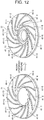
- Figure 12 is a perspective view of a hub before and after a centering fixture is mounted.
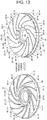
- Figure 13 is a perspective view of the hub before and after divided cores are disposed.
- Figure 14 is a perspective view of one divided core as viewed from the back side.
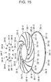
- Figure 15 is an exploded perspective view of the divided cores as viewed from the back side, for describing inner circumference spacers and outer circumference spacers.
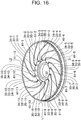
- Figure 16 is a perspective view of the hub when the inner circumference spacers, the outer circumference spacers and the divided cores are disposed.
- Figure 17 is a partial perspective view of the hub taken along a polyline L1 and a straight line L2 in Figure 16 .
- inner circumference spacers 34-1 to 34-13 and outer circumference spacers 35-1 to 35-13 are omitted.
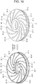
- Figure 18 is a perspective view of the hub before and after a cover is disposed.
- Figure 19 is a flowchart showing an example of the method of manufacturing the impeller according to the second embodiment.
- a hub 31 provided with a plurality of blades 41-1 to 41-13 is formed.
- the hub 31 is carved from a forging material by machining, and thereby, the blades 41-1 to 41-13 are integrally carved.
- the hub 31 has a disk shape, and a hollow space is formed at the center of the hub 31.
- the plurality of blades 41-1 to 41-13 are provided from the center of the hub 31 at an equal angular interval, and the shapes of the blades 41-1 to 41-13 are roughly the same as each other.
- Step S102 Next, as shown in Figure 12 , a centering fixture 32 is mounted in the hollow space formed in the hub 31.
- Step S103 Next, divided cores 33-1 to 33-13, inner circumference spacers 34-1 to 34-13 and outer circumference spacers 35-1 to 35-13 are disposed. Specifically, as shown in Figure 13 , the plurality of divided cores 33-1 to 33-13 is disposed on the hub 31, such that each of the divided cores 33-1 to 33-13 is disposed at each interspace of adjacent blades. As shown in Figure 13 and Figure 17 , the divided cores 33-1 to 33-13 protrude to the inner circumference side than from the hub 31.
- the shapes of the divided cores are roughly the same as each other, and the shape of each divided core has a shape shown in Figure 14 .
- the wooden pattern for molding the divided cores 33-1 to 33-13 has a small size, it is possible to use a small and inexpensive additive manufacturing device for resin shaping, in the fabrication of the wooded pattern, and it is possible to fabricate a wooden pattern (resin pattern) having a relatively high shape accuracy at low cost in a short time. Therefore, it is possible to make the divided cores 33-1 to 33-13 at low cost in a short time.
- the additive manufacturing device it is possible to mass-produce the same divided cores, based on the same 3D model.
- the inner circumference spacers 34-1 to 34-13 are provided at interspaces of adjacent divided cores 33-1 to 33-13, on the inner circumference side. By this configuration, it is possible to perform the positioning of the divided cores 33-1 to 33-13.
- the heights of the inner circumference spacers 34-1 to 34-13 when the inner circumference spacers 34-1 to 34-13 are provided are lower than the heights of the divided cores 33-1 to 33-13.
- the inert gas is supplied from the inner circumference side, such that the inert gas flows through a passage that is formed between the hub 31 and the cover 36.
- the outer circumference spacers 35-1 to 35-13 are respectively disposed at interspaces of adjacent blades 41-1 to 41-13 on the outer circumference sides of the divided cores 33-1 to 33-13.
- the divided cores are disposed such that the back surfaces of the inner circumference sides of the divided cores contact with the front surface of the centering fixture 32.
- the divided cores support the inner circumference side of the cover, and therefore, it is possible to avoid the inner circumference side of the cover provided on the cores from falling down due to the welding.
- the thicknesses of the divided cores 33-1 to 33-13 are smaller than the heights of the blades with respect to the front surface of the hub 31, by a predetermined length.
- the predetermined length is a length corresponding to decrease amount of the heights of the blades when the top surfaces of the blades melt by the welding and thereby the blades contract. Thereby, the top surfaces of the blades melt by the welding, and thereby, the blades contract so that the heights become roughly the same as the thicknesses of the divided cores 33-1 to 33-13. Therefore, it is possible to prevent unnecessary force from being applied to the divided cores 33-1 to 33-13.
- the divided cores 33-1 to 33-13 need to be removed after the welding, and therefore, it is preferable that the divided cores 33-1 to 33-13 be made of a raw material that can be physically broken readily.
- the divided cores 33-1 to 33-13 are formed using a material described in Patent Literature 1. By using such a material, the physical removal of the divided cores 33-1 to 33-13 becomes easy.
- Step S104 Next, as shown in Figure 18 , the cover 36 on which grooves 37-1 to 37-13 conforming to the shapes of the blades 41-1 to 41-13 are formed is disposed on the hub 31 and the divided cores 33-1 to 33-13.
- Step S105 Next, the cover 36 and the blades 41-1 to 41-13 are welded, while the inert gas is supplied from the inner circumference side.
- the inert gas is supplied from the inner circumference side, such that the inert gas flows through the passage that is formed between the hub 31 and the cover 36.
- the presence of the outer circumference spacers 35-1 to 35-13 can restrain the inert gas from leaking to the outside. It is possible to make the inert gas reach a penetration bead that is generated at the time of the welding of the blades, and it is possible to avoid the penetration bead from being oxidized.
- Step S106 Next, a heat treatment is performed. For example, the temperature is slowly increased, and then is slowly decreased. Thereby, it is possible to let out residual stress.
- Step S107 Next, an outer circumference portion is carved. Thereby, the outer circumference spacers 35-1 to 35-13 are removed.
- Step S108 Next, the divided cores 33-1 to 33-13 are physically broken by a steel wire or the like.
- Step S109 Next, the impeller is finished into a desired shape by machining. Thereby, the impeller is completed.
- the method of manufacturing the impeller according to the second embodiment includes: the step of forming the hub 31 that is provided with the plurality of blades 41-1 to 41-13; the step of disposing the plurality of divided cores 33-1 to 33-13 on the hub 31, such that the divided cores are respectively disposed at the interspaces of adjacent blades; the step of disposing the cover 36 on the hub 31 and the divided cores 33-1 to 33-13; and the step of welding the cover 36 and the blades 41-1 to 41-13.
- each of the divided cores 33-1 to 33-13 has light, and it is possible to avoid the collapse due to its own weight. Further, it is possible to decrease the bending moment that is generated in the divided cores 33-1 to 33-13 when the divided cores 33-1 to 33-13 are held up, and to secure the strength allowing works such as the fabrication of the divided cores 33-1 to 33-13 and welding setup (the assembly of the divided core). Since each of the divided cores 33-1 to 33-13 has a small size, the deformation amount during the hardening treatment is also small, and combined with the division structure, it is possible to improve the workability for mounting (assembling) the divided cores to the impeller. Further, even when the divided cores 33-1 to 33-13 become unusable due to deformation or damage, one of the divided cores 33-1 to 33-13 only needs to be replaced because of the division structure, and therefore, the influence on fabrication cost is decreased.
- the blades 41-1 to 41-13 are formed on the hub 31, but without being limited to this, the blades 41-1 to 41-13 may be formed on the cover 36.
- the method of manufacturing the impeller may include: a step of forming a cover that is provided with a plurality of blades; a step of disposing a plurality of divided cores on the cover, such that the divided cores are respectively disposed at interspaces of adjacent blades; a step of disposing a hub on the cover and the divided cores; and a step of welding the hub and the blades.
Landscapes
- Engineering & Computer Science (AREA)
- Mechanical Engineering (AREA)
- General Engineering & Computer Science (AREA)
- Physics & Mathematics (AREA)
- Plasma & Fusion (AREA)
- Structures Of Non-Positive Displacement Pumps (AREA)
Claims (17)
- Verfahren zur Herstellung eines Laufrades (1), wobei das Verfahren Folgendes aufweist:einen Schritt des Formens einer Abdeckung (3), die mit einer Vielzahl von Schaufeln (4) versehen ist,einen Schritt des Anordnens eines Kerns (10) auf der Abdeckung (3), so dass der Kern (10) zwischen den Schaufeln (4) angeordnet ist;einen Schritt des Anordnens einer Nabe (2) auf den Schaufeln (4), wobei die Nabe (2) eine Platte ist, in der Nuten (5) geformt sind, die an die Formen der Schaufeln (4) angepasst sind; undeinen Schritt des Schweißens der Nabe und der Schaufeln (4),wobeiDurchgangslöcher (14), die an die Formen der Schaufeln (4) angepasst sind, an dem Kern (10) vorgesehen sind, so dass die Schaufeln (4) in den Kern (10) eingepasst werden, wenn der Kern (10) angeordnet wird,ein Entlüftungsloch (15) an dem Kern (10) vorgesehen ist unddas Verfahren weiter einen Schritt des Befestigens eines Bandes (16) über einem Spalt zwischen der Nabe (2) und dem Kern (10) aufweist, unddas Füllen eines inerten Gases von dem Entlüftungsloch (15) in den Raum unter der Nabe (2), der Abdeckung (3) und dem Kern (10) vor dem Schritt des Schweißens der Nabe (2) und der Schaufeln (4).
- Verfahren zur Herstellung des Laufrades (1) nach Anspruch 1, wobei das Verfahren weiter einen Schritt des Zerbrechens und Entfernens des Kerns (10) aufweist, wenn eine Temperatur der Nabe (2) nach dem Schritt des Schweißens der Nabe (2) und der Schaufeln (4) niedriger als eine vorbestimmte Temperatur wird.
- Verfahren zur Herstellung des Laufrades (1) nach Anspruch 1 oder 2, wobei
die Durchgangslöcher (14) des Kerns Formen haben, die ähnlich den Formen der Schaufeln (4) sind, und wobei sie in Umfangsbreite breiter als die Schaufeln (4) sind. - Verfahren zur Herstellung des Laufrades (1) nach einem der Ansprüche 1 bis 3, wobei
die Anzahl der Durchgangslöcher (15), die in dem Kern (10) vorgesehen sind, die gleiche ist wie die Anzahl der Schaufeln (4) und wobei
beim Schritt des Anordnens des Kerns (10) der Kern (10) durch Überlappen des Kerns (10) auf der Abdeckung (3) so angeordnet wird, dass horizontale Positionen der Vielzahl von Schaufeln (4) ungefähr mit horizontalen Positionen der entsprechenden Durchgangslöcher (14) zusammenfallen. - Verfahren zur Herstellung des Laufrades (1) nach einem der Ansprüche 1 bis 4, wobeidie Abdeckung (3) und der Kern (10) Scheibenformen haben, undbeim Schritt des Anordnens des Kerns (10) auf der Abdeckung (3) der Kern (10) so angeordnet wird, dass eine Mittelachse des Kerns (10) ungefähr mit einer Mittelachse der Abdeckung (3) zusammenfällt.
- Verfahren zur Herstellung des Laufrades (1) nach einem der Ansprüche 1 bis 5, wobeidie Nabe (2) und der Kern (10) Scheibenformen haben, undbeim Schritt des Anordnens der Nabe (2) auf den Schaufeln (14) die Nabe (2) so angeordnet wird, dass eine Mittelachse der Nabe (2) ungefähr mit einer Mittelachse der Abdeckung (3) zusammenfällt.
- Verfahren zur Herstellung des Laufrades (1) nach einem der Ansprüche 1 bis 6, wobei
der Kern (10) unter Verwendung eines Rohmaterials geformt wird, welches beim Präzisionsguss verwendet wird. - Verfahren zur Herstellung des Laufrades (1) nach einem der Ansprüche 1 bis 7, wobei
die Abdeckung (3) eine Abdeckung (3) ist, die integral mit den Schaufeln (4) durch maschinelle Bearbeitung herausgearbeitet ist. - Verfahren zur Herstellung des Laufrades (1) nach einem der Ansprüche 1 bis 8, wobeiLöcher (9) zum Schweißen in den Nuten (5) der Nabe (2) vorgesehen sind, undbeim Schritt des Schweißens der Nabe (2) und der Schaufeln (4) ein Schweißmaterial durch die Löcher (9) zum Schweißen gegossen wird, und die Nabe (2) und die Schaufeln (4) geschweißt werden.
- Verfahren zur Herstellung des Laufrades (1) nach einem der Ansprüche 1 bis 9, wobei
das Laufrad (1) ein Laufrad einer sich drehenden Maschine ist. - Verfahren zur Herstellung eines Laufrades (1), wobei das Verfahren Folgendes aufweist:einen Schritt des Formens einer Nabe (2), die mit einer Vielzahl von Schaufeln (4) versehen ist;einen Schritt des Anordnens eines Kerns (10) auf der Nabe (2), so dass der Kern (10) zwischen den Schaufeln (4) angeordnet ist;einen Schritt des Anordnens einer Abdeckung (3) auf den Schaufeln (4),wobei die Abdeckung (3) eine Platte ist, in der Nuten (5) geformt sind, die an Formen der Schaufeln (4) angepasst sind; undeinen Schritt des Schweißens der Abdeckung (3) und der Schaufeln (4),wobei Durchgangslöcher (14), die an die Formen der Schaufeln (4) angepasst sind, an dem Kern (10) vorgesehen sind, so dass die Schaufeln (4) in den Kern (10) eingepasst werden, wenn der Kern (10) angeordnet wird, wobei ein Entlüftungsloch (15) an dem Kern (10) vorgesehen ist, undwobei das Verfahren weiter einen Schritt des Befestigens eines Bandes (16) über einem Spalt zwischen der Nabe (2) und dem Kern (10) und des Füllens eines inerten Gases von dem Entlüftungsloch (15) in einen Raum unter der Nabe (2), der Abdeckung (3) und dem Kern (10) aufweist, undzwar vor dem Schritt des Schweißens der Abdeckung (3) und der Schaufeln (4).
- Verfahren zur Herstellung eines Laufrades (1), wobei das Verfahren Folgendes aufweist:einen Schritt des Formens einer Nabe (31), die mit einer Vielzahl von Schaufeln (41-1 bis 41-13) versehen ist;einen Schritt des Anordnens einer Vielzahl von geteilten Kernen (33-1 bis 33-13) auf der Nabe (31), so dass jeder der geteilten Kerne (33-1 bis 33-13) bei jedem Zwischenraum von den benachbarten Schaufeln (41-1 bis 41-13) angeordnet ist;einen Schritt des Anordnens einer Abdeckung (36) auf der Nabe und den geteilten Kernen (33-1 bis 33-13); undeinen Schritt des Schweißens der Abdeckung (36) und der Schaufeln (41-1 bis 41-13), wobeiein hohler Raum in der Mitte der Nabe (31) geformt wird,die geteilten Kerne (33-1 bis 33-13) zu einer Innenumfangsseite der Nabe (31) vorstehen,das Verfahren einen Schritt aufweist, Innenumfangsabstandshalter (34-1 bis 34-13) an Zwischenräumen der benachbarten geteilten Kerne (33-1 bis 33-13) an der Innenumfangsseite vorzusehen, und zwar beim Schritt des Anordnens der geteilten Kerne (33-1 bis 33-13),Höhen der Innenumfangsabstandshalter (34-1 bis 34-13) niedriger sind als Höhen der geteilten Kerne (33-1 bis 33-13), wenn die Innenumfangsabstandshalter (34-1 bis 34-13) vorgesehen bzw. angeordnet werden, undbeim Schritt des Schweißens der Abdeckung (36) und der Schaufeln (41-1 bis 41-13) ein inertes Gas von einer Innenumfangsseite so geliefert wird,dass das inerte Gas durch einen Durchlass fließt, der zwischen der Nabe (31) und der Abdeckung (36) geformt ist.
- Verfahren zur Herstellung der Laufrades nach Anspruch 12, wobeidas Verfahren weiter einen Schritt des Montierens einer Zentrierungshalterung (32) in dem hohlen Raum aufweist, der in der Nabe (31) geformt ist,und zwar nach dem Schritt des Formens der Nabe (31) und bevor die geteilten Kerne (33-1 bis 33-13) angeordnet werden, undbei dem Schritt des Anordnens der geteilten Kerne (33-1 bis 33-13) die geteilten Kerne (33-1 bis 33-13) so angeordnet werden, dass Hinterseiten der Innenumfangseiten der geteilten Kerne mit einer Vorderseite der Zentrierungshalterung (32) in Kontakt sind.
- Verfahren zur Herstellung des Laufrades nach Anspruch 12 oder 13, wobei das Verfahren weiter einen Schritt aufweist, jeweils Außenumfangsabstandshalter (35-1 bis 35-13) bei Zwischenräumen der benachbarten Schaufeln (41-1 bis 41-13) an Außenumfangsseiten der geteilten Kerne (33-1 bis 33-13) anzuordnen, und zwar beim Schritt des Anordnens der geteilten Kerne (33-1 bis 33-13).
- Verfahren zur Herstellung des Laufrades nach einem der Ansprüche 12 bis 14, wobei
die Vielzahl von Schaufeln (41-1 bis 41-13) von einer Mitte der Nabe (31) in einem gleichen Winkelintervall vorgesehen ist bzw. sind, und wobei Formen der Schaufeln (41-1 bis 41-13) ungefähr gleich zueinander sind, und wobei
Formen der geteilten Kerne (33-1 bis 33-13) ungefähr gleich zueinander sind. - Verfahren zur Herstellung des Laufrades nach einem der Ansprüche 12 bis 15, wobei
Dicken der geteilten Kerne (33-1 bis 33-13) kleiner sind als Höhen der Schaufeln (41-1 bis 41-13) bezüglich einer Vorderseite der Nabe (31), und zwar um eine vorbestimmte Länge. - Verfahren zur Herstellung eines Laufrades, wobei das Verfahren Folgendes aufweist:einen Schritt des Formens einer Abdeckung (36), die mit einer Vielzahl von Schaufeln (41-1 bis 41-13) versehen ist;einen Schritt des Anordnens einer Vielzahl von geteilten Kernen (33-1 bis 33-13) auf der Abdeckung (36), so dass jeder der geteilten Kerne (33-1 bis 33-13) jeweils bei einem Zwischenraum der benachbarten Schaufeln angeordnet ist;einen Schritt des Anordnens einer Nabe (31) auf der Abdeckung und den geteilten Kernen (33-1 bis 33-13); undeinen Schritt des Schweißens der Nabe (31) und der Schaufeln (41-1 bis 41-13), wobei ein hohler Raum in einer Mitte der Nabe (31) geformt wird, wobei die geteilten Kerne (33-1 bis 33-13) zu einer Innenumfangsseite der Nabe (31) vorstehen,wobei das Verfahren einen Schritt des Vorsehens von Innenumfangsabstandshaltern (34-1 bis 34-13) bei Zwischenräumen von benachbarten geteilten Kernen (33-1 bis 33-13) an der Innenumfangsseite aufweist, und zwar beim Schritt des Anordnens der geteilten Kerne (33-1 bis 33-13),wobei Höhen der Innenumfangsabstandshalter (34-1 bis 34-13) niedriger sind als Höhen der geteilten Kerne (33-1 bis 33-13), wenn die Innenumfangsabstandshalter (34-1 bis 34-13) vorgesehen bzw. angeordnet werden, und wobei
beim Schritt des Schweißens der Nabe (31) und der Schaufeln (41-1 bis 41-13) ein inertes Gas von einer Innenumfangsseite so geliefert wird, dass das inerte Gas durch einen Durchlass fließt, der zwischen der Nabe (31) und der Abdeckung (36) geformt ist.
Applications Claiming Priority (3)
| Application Number | Priority Date | Filing Date | Title |
|---|---|---|---|
| JP2015211703 | 2015-10-28 | ||
| JP2016190866A JP6758144B2 (ja) | 2015-10-28 | 2016-09-29 | 羽根車の製造方法 |
| PCT/JP2016/081401 WO2017073500A1 (ja) | 2015-10-28 | 2016-10-24 | 羽根車の製造方法 |
Publications (3)
| Publication Number | Publication Date |
|---|---|
| EP3369937A1 EP3369937A1 (de) | 2018-09-05 |
| EP3369937A4 EP3369937A4 (de) | 2019-06-26 |
| EP3369937B1 true EP3369937B1 (de) | 2021-12-29 |
Family
ID=58712965
Family Applications (1)
| Application Number | Title | Priority Date | Filing Date |
|---|---|---|---|
| EP16859730.0A Active EP3369937B1 (de) | 2015-10-28 | 2016-10-24 | Verfahren zur herstellung eines laufrads |
Country Status (4)
| Country | Link |
|---|---|
| US (1) | US10710186B2 (de) |
| EP (1) | EP3369937B1 (de) |
| JP (1) | JP6758144B2 (de) |
| CN (1) | CN107949704A (de) |
Families Citing this family (7)
| Publication number | Priority date | Publication date | Assignee | Title |
|---|---|---|---|---|
| CN109079362B (zh) * | 2018-10-17 | 2020-11-03 | 江西省莲花水轮机厂有限公司 | 水泵叶轮的加工方法 |
| US11598347B2 (en) * | 2019-06-28 | 2023-03-07 | Trane International Inc. | Impeller with external blades |
| CN111331297B (zh) * | 2020-04-09 | 2024-11-29 | 上海中韩杜科泵业制造有限公司 | 一种水泵导叶焊接工装 |
| CN111536056B (zh) * | 2020-05-07 | 2021-09-21 | 周永新 | 一种用于输送和压缩特殊气体的高速多级鼓风机 |
| CN112848120B (zh) * | 2021-02-03 | 2024-12-27 | 联塑科技发展(武汉)有限公司 | 一种模具滑块型芯叶轮形气冷结构 |
| CN115405561A (zh) * | 2022-09-02 | 2022-11-29 | 重庆通用工业(集团)有限责任公司 | 大型压缩机高强钢叶轮组合装置及制造方法 |
| CN120038504B (zh) * | 2025-04-03 | 2025-08-15 | 山东亨泉能源科技有限公司 | 一种离心泵配件定位加工装置 |
Family Cites Families (9)
| Publication number | Priority date | Publication date | Assignee | Title |
|---|---|---|---|---|
| JPS5499039A (en) * | 1978-01-23 | 1979-08-04 | Ebara Mfg | Production of core mold for precise casting |
| US4754118A (en) * | 1985-05-16 | 1988-06-28 | Mitsubishi Jukogyo Kabushiki Kaisha | Method for fabricating a structural assembly having narrow gaps |
| JPS61262465A (ja) * | 1985-05-16 | 1986-11-20 | Mitsubishi Heavy Ind Ltd | 狭間隙部材の溶接組立て方法 |
| JPH01205889A (ja) * | 1988-02-10 | 1989-08-18 | Mitsubishi Heavy Ind Ltd | 接合方法 |
| JP2862102B2 (ja) * | 1991-06-14 | 1999-02-24 | 三菱重工業株式会社 | コンプレッサー用羽根車の製造方法 |
| DE69430544T2 (de) * | 1993-07-07 | 2002-12-05 | Smc K.K., Tokio/Tokyo | Verbindungsmechanismus für strukturelemente |
| JP5061836B2 (ja) | 2007-10-10 | 2012-10-31 | 株式会社日立プラントテクノロジー | 羽根車の溶接方法及び羽根車 |
| CN201900705U (zh) * | 2010-07-21 | 2011-07-20 | 台州市新立模塑有限公司 | 汽车仪表盘储物盖模具的气辅减胶机构 |
| CN104259793B (zh) * | 2014-08-27 | 2017-07-07 | 张家港市海工船舶机械制造有限公司 | 一种叶轮制造方法及其由该方法制造的叶轮 |
-
2016
- 2016-09-29 JP JP2016190866A patent/JP6758144B2/ja active Active
- 2016-10-24 EP EP16859730.0A patent/EP3369937B1/de active Active
- 2016-10-24 US US15/770,944 patent/US10710186B2/en active Active
- 2016-10-24 CN CN201680051415.9A patent/CN107949704A/zh active Pending
Also Published As
| Publication number | Publication date |
|---|---|
| US20180333797A1 (en) | 2018-11-22 |
| JP6758144B2 (ja) | 2020-09-23 |
| US10710186B2 (en) | 2020-07-14 |
| EP3369937A4 (de) | 2019-06-26 |
| EP3369937A1 (de) | 2018-09-05 |
| JP2017082769A (ja) | 2017-05-18 |
| CN107949704A (zh) | 2018-04-20 |
Similar Documents
| Publication | Publication Date | Title |
|---|---|---|
| EP3369937B1 (de) | Verfahren zur herstellung eines laufrads | |
| JP5130582B2 (ja) | ブリスクの製造方法および方法を実施するための金型 | |
| US20090261669A1 (en) | Method of making and device for cooling rotor motor cores | |
| US20130106233A1 (en) | Squirrel-cage rotor and manufacturing method of squirrel-cage rotor | |
| JPWO2008105461A1 (ja) | 薄肉中空鋳物用中子およびそれを用いた製造方法による薄肉中空鋳物 | |
| US20110135483A1 (en) | Composite turbine blade and method of manufacture thereof | |
| WO2017073500A1 (ja) | 羽根車の製造方法 | |
| JP7117160B2 (ja) | 回転電機用フレームの製造方法 | |
| US2711492A (en) | Stator for electric motors | |
| KR20100010552A (ko) | 알루미늄 회전자 원심주조방법 | |
| US1470507A (en) | Method of making rotor elements for elastic-fluid turbines | |
| KR102183683B1 (ko) | 터빈용 실링 세그먼트의 제조방법 및 제조장치 | |
| EP2570207B1 (de) | Form zum Gießen eines Werkstücks mit einem oder mehreren Gussstiften | |
| CN104113169B (zh) | 一种电机转子铁芯叠压粘接处理方法 | |
| KR101140296B1 (ko) | 가스터빈용 블레이드링의 원심주조에 의한 제조방법 | |
| CN107671244A (zh) | 一种包含水道的电机壳砂芯及其制造方法 | |
| JP5916510B2 (ja) | 回転機械用のブレードの製造方法及びこれに用いられるバランスウェイトの鋳込み用治具 | |
| KR101864323B1 (ko) | 쿨러 조립체 및 쿨러 조립체의 제조 방법 | |
| JP5891079B2 (ja) | ガイドベーンおよびガイドベーン製法 | |
| JP3592664B2 (ja) | タービンケーシングの製造方法 | |
| KR20190115190A (ko) | 전기모터의 베어링 쉴드 제조방법 | |
| US9259781B2 (en) | Case corrosion-resistant liners in nozzles and case bodies to eliminate overlays | |
| JP2018187864A (ja) | タイヤ用モールドの製造方法 | |
| JP2005171772A (ja) | フランシス型水車、ポンプまたはポンプ水車のランナおよびその製造方法 | |
| JP4977562B2 (ja) | 積層ゴム支承体の製造方法 |
Legal Events
| Date | Code | Title | Description |
|---|---|---|---|
| STAA | Information on the status of an ep patent application or granted ep patent |
Free format text: STATUS: THE INTERNATIONAL PUBLICATION HAS BEEN MADE |
|
| PUAI | Public reference made under article 153(3) epc to a published international application that has entered the european phase |
Free format text: ORIGINAL CODE: 0009012 |
|
| STAA | Information on the status of an ep patent application or granted ep patent |
Free format text: STATUS: REQUEST FOR EXAMINATION WAS MADE |
|
| 17P | Request for examination filed |
Effective date: 20180430 |
|
| AK | Designated contracting states |
Kind code of ref document: A1 Designated state(s): AL AT BE BG CH CY CZ DE DK EE ES FI FR GB GR HR HU IE IS IT LI LT LU LV MC MK MT NL NO PL PT RO RS SE SI SK SM TR |
|
| AX | Request for extension of the european patent |
Extension state: BA ME |
|
| DAV | Request for validation of the european patent (deleted) | ||
| DAX | Request for extension of the european patent (deleted) | ||
| A4 | Supplementary search report drawn up and despatched |
Effective date: 20190523 |
|
| RIC1 | Information provided on ipc code assigned before grant |
Ipc: F01D 5/04 20060101ALI20190517BHEP Ipc: F04D 29/02 20060101ALI20190517BHEP Ipc: F04D 29/62 20060101ALI20190517BHEP Ipc: F04D 29/28 20060101ALI20190517BHEP Ipc: B23K 101/00 20060101ALI20190517BHEP Ipc: F04D 29/22 20060101AFI20190517BHEP Ipc: B23K 9/02 20060101ALI20190517BHEP Ipc: B23K 9/038 20060101ALI20190517BHEP Ipc: B23K 9/16 20060101ALI20190517BHEP Ipc: B23K 9/00 20060101ALI20190517BHEP |
|
| STAA | Information on the status of an ep patent application or granted ep patent |
Free format text: STATUS: EXAMINATION IS IN PROGRESS |
|
| 17Q | First examination report despatched |
Effective date: 20210222 |
|
| GRAP | Despatch of communication of intention to grant a patent |
Free format text: ORIGINAL CODE: EPIDOSNIGR1 |
|
| STAA | Information on the status of an ep patent application or granted ep patent |
Free format text: STATUS: GRANT OF PATENT IS INTENDED |
|
| INTG | Intention to grant announced |
Effective date: 20210729 |
|
| GRAS | Grant fee paid |
Free format text: ORIGINAL CODE: EPIDOSNIGR3 |
|
| GRAA | (expected) grant |
Free format text: ORIGINAL CODE: 0009210 |
|
| STAA | Information on the status of an ep patent application or granted ep patent |
Free format text: STATUS: THE PATENT HAS BEEN GRANTED |
|
| AK | Designated contracting states |
Kind code of ref document: B1 Designated state(s): AL AT BE BG CH CY CZ DE DK EE ES FI FR GB GR HR HU IE IS IT LI LT LU LV MC MK MT NL NO PL PT RO RS SE SI SK SM TR |
|
| REG | Reference to a national code |
Ref country code: GB Ref legal event code: FG4D |
|
| REG | Reference to a national code |
Ref country code: CH Ref legal event code: EP |
|
| REG | Reference to a national code |
Ref country code: AT Ref legal event code: REF Ref document number: 1458889 Country of ref document: AT Kind code of ref document: T Effective date: 20220115 |
|
| REG | Reference to a national code |
Ref country code: IE Ref legal event code: FG4D |
|
| REG | Reference to a national code |
Ref country code: DE Ref legal event code: R096 Ref document number: 602016067934 Country of ref document: DE |
|
| REG | Reference to a national code |
Ref country code: LT Ref legal event code: MG9D |
|
| PG25 | Lapsed in a contracting state [announced via postgrant information from national office to epo] |
Ref country code: RS Free format text: LAPSE BECAUSE OF FAILURE TO SUBMIT A TRANSLATION OF THE DESCRIPTION OR TO PAY THE FEE WITHIN THE PRESCRIBED TIME-LIMIT Effective date: 20211229 Ref country code: LT Free format text: LAPSE BECAUSE OF FAILURE TO SUBMIT A TRANSLATION OF THE DESCRIPTION OR TO PAY THE FEE WITHIN THE PRESCRIBED TIME-LIMIT Effective date: 20211229 Ref country code: FI Free format text: LAPSE BECAUSE OF FAILURE TO SUBMIT A TRANSLATION OF THE DESCRIPTION OR TO PAY THE FEE WITHIN THE PRESCRIBED TIME-LIMIT Effective date: 20211229 Ref country code: BG Free format text: LAPSE BECAUSE OF FAILURE TO SUBMIT A TRANSLATION OF THE DESCRIPTION OR TO PAY THE FEE WITHIN THE PRESCRIBED TIME-LIMIT Effective date: 20220329 |
|
| REG | Reference to a national code |
Ref country code: NL Ref legal event code: MP Effective date: 20211229 |
|
| REG | Reference to a national code |
Ref country code: AT Ref legal event code: MK05 Ref document number: 1458889 Country of ref document: AT Kind code of ref document: T Effective date: 20211229 |
|
| PG25 | Lapsed in a contracting state [announced via postgrant information from national office to epo] |
Ref country code: SE Free format text: LAPSE BECAUSE OF FAILURE TO SUBMIT A TRANSLATION OF THE DESCRIPTION OR TO PAY THE FEE WITHIN THE PRESCRIBED TIME-LIMIT Effective date: 20211229 Ref country code: NO Free format text: LAPSE BECAUSE OF FAILURE TO SUBMIT A TRANSLATION OF THE DESCRIPTION OR TO PAY THE FEE WITHIN THE PRESCRIBED TIME-LIMIT Effective date: 20220329 Ref country code: LV Free format text: LAPSE BECAUSE OF FAILURE TO SUBMIT A TRANSLATION OF THE DESCRIPTION OR TO PAY THE FEE WITHIN THE PRESCRIBED TIME-LIMIT Effective date: 20211229 Ref country code: HR Free format text: LAPSE BECAUSE OF FAILURE TO SUBMIT A TRANSLATION OF THE DESCRIPTION OR TO PAY THE FEE WITHIN THE PRESCRIBED TIME-LIMIT Effective date: 20211229 Ref country code: GR Free format text: LAPSE BECAUSE OF FAILURE TO SUBMIT A TRANSLATION OF THE DESCRIPTION OR TO PAY THE FEE WITHIN THE PRESCRIBED TIME-LIMIT Effective date: 20220330 |
|
| PG25 | Lapsed in a contracting state [announced via postgrant information from national office to epo] |
Ref country code: NL Free format text: LAPSE BECAUSE OF FAILURE TO SUBMIT A TRANSLATION OF THE DESCRIPTION OR TO PAY THE FEE WITHIN THE PRESCRIBED TIME-LIMIT Effective date: 20211229 |
|
| PG25 | Lapsed in a contracting state [announced via postgrant information from national office to epo] |
Ref country code: SM Free format text: LAPSE BECAUSE OF FAILURE TO SUBMIT A TRANSLATION OF THE DESCRIPTION OR TO PAY THE FEE WITHIN THE PRESCRIBED TIME-LIMIT Effective date: 20211229 Ref country code: SK Free format text: LAPSE BECAUSE OF FAILURE TO SUBMIT A TRANSLATION OF THE DESCRIPTION OR TO PAY THE FEE WITHIN THE PRESCRIBED TIME-LIMIT Effective date: 20211229 Ref country code: RO Free format text: LAPSE BECAUSE OF FAILURE TO SUBMIT A TRANSLATION OF THE DESCRIPTION OR TO PAY THE FEE WITHIN THE PRESCRIBED TIME-LIMIT Effective date: 20211229 Ref country code: PT Free format text: LAPSE BECAUSE OF FAILURE TO SUBMIT A TRANSLATION OF THE DESCRIPTION OR TO PAY THE FEE WITHIN THE PRESCRIBED TIME-LIMIT Effective date: 20220429 Ref country code: ES Free format text: LAPSE BECAUSE OF FAILURE TO SUBMIT A TRANSLATION OF THE DESCRIPTION OR TO PAY THE FEE WITHIN THE PRESCRIBED TIME-LIMIT Effective date: 20211229 Ref country code: EE Free format text: LAPSE BECAUSE OF FAILURE TO SUBMIT A TRANSLATION OF THE DESCRIPTION OR TO PAY THE FEE WITHIN THE PRESCRIBED TIME-LIMIT Effective date: 20211229 Ref country code: CZ Free format text: LAPSE BECAUSE OF FAILURE TO SUBMIT A TRANSLATION OF THE DESCRIPTION OR TO PAY THE FEE WITHIN THE PRESCRIBED TIME-LIMIT Effective date: 20211229 |
|
| PG25 | Lapsed in a contracting state [announced via postgrant information from national office to epo] |
Ref country code: PL Free format text: LAPSE BECAUSE OF FAILURE TO SUBMIT A TRANSLATION OF THE DESCRIPTION OR TO PAY THE FEE WITHIN THE PRESCRIBED TIME-LIMIT Effective date: 20211229 Ref country code: AT Free format text: LAPSE BECAUSE OF FAILURE TO SUBMIT A TRANSLATION OF THE DESCRIPTION OR TO PAY THE FEE WITHIN THE PRESCRIBED TIME-LIMIT Effective date: 20211229 |
|
| PG25 | Lapsed in a contracting state [announced via postgrant information from national office to epo] |
Ref country code: IS Free format text: LAPSE BECAUSE OF FAILURE TO SUBMIT A TRANSLATION OF THE DESCRIPTION OR TO PAY THE FEE WITHIN THE PRESCRIBED TIME-LIMIT Effective date: 20220429 |
|
| REG | Reference to a national code |
Ref country code: DE Ref legal event code: R097 Ref document number: 602016067934 Country of ref document: DE |
|
| PG25 | Lapsed in a contracting state [announced via postgrant information from national office to epo] |
Ref country code: DK Free format text: LAPSE BECAUSE OF FAILURE TO SUBMIT A TRANSLATION OF THE DESCRIPTION OR TO PAY THE FEE WITHIN THE PRESCRIBED TIME-LIMIT Effective date: 20211229 Ref country code: AL Free format text: LAPSE BECAUSE OF FAILURE TO SUBMIT A TRANSLATION OF THE DESCRIPTION OR TO PAY THE FEE WITHIN THE PRESCRIBED TIME-LIMIT Effective date: 20211229 |
|
| PLBE | No opposition filed within time limit |
Free format text: ORIGINAL CODE: 0009261 |
|
| STAA | Information on the status of an ep patent application or granted ep patent |
Free format text: STATUS: NO OPPOSITION FILED WITHIN TIME LIMIT |
|
| 26N | No opposition filed |
Effective date: 20220930 |
|
| PG25 | Lapsed in a contracting state [announced via postgrant information from national office to epo] |
Ref country code: SI Free format text: LAPSE BECAUSE OF FAILURE TO SUBMIT A TRANSLATION OF THE DESCRIPTION OR TO PAY THE FEE WITHIN THE PRESCRIBED TIME-LIMIT Effective date: 20211229 |
|
| PG25 | Lapsed in a contracting state [announced via postgrant information from national office to epo] |
Ref country code: MC Free format text: LAPSE BECAUSE OF FAILURE TO SUBMIT A TRANSLATION OF THE DESCRIPTION OR TO PAY THE FEE WITHIN THE PRESCRIBED TIME-LIMIT Effective date: 20211229 Ref country code: IT Free format text: LAPSE BECAUSE OF FAILURE TO SUBMIT A TRANSLATION OF THE DESCRIPTION OR TO PAY THE FEE WITHIN THE PRESCRIBED TIME-LIMIT Effective date: 20211229 |
|
| REG | Reference to a national code |
Ref country code: CH Ref legal event code: PL |
|
| P01 | Opt-out of the competence of the unified patent court (upc) registered |
Effective date: 20230428 |
|
| REG | Reference to a national code |
Ref country code: BE Ref legal event code: MM Effective date: 20221031 |
|
| GBPC | Gb: european patent ceased through non-payment of renewal fee |
Effective date: 20221024 |
|
| PG25 | Lapsed in a contracting state [announced via postgrant information from national office to epo] |
Ref country code: LU Free format text: LAPSE BECAUSE OF NON-PAYMENT OF DUE FEES Effective date: 20221024 |
|
| PG25 | Lapsed in a contracting state [announced via postgrant information from national office to epo] |
Ref country code: LI Free format text: LAPSE BECAUSE OF NON-PAYMENT OF DUE FEES Effective date: 20221031 Ref country code: FR Free format text: LAPSE BECAUSE OF NON-PAYMENT OF DUE FEES Effective date: 20221031 Ref country code: CH Free format text: LAPSE BECAUSE OF NON-PAYMENT OF DUE FEES Effective date: 20221031 |
|
| PG25 | Lapsed in a contracting state [announced via postgrant information from national office to epo] |
Ref country code: BE Free format text: LAPSE BECAUSE OF NON-PAYMENT OF DUE FEES Effective date: 20221031 |
|
| PG25 | Lapsed in a contracting state [announced via postgrant information from national office to epo] |
Ref country code: IE Free format text: LAPSE BECAUSE OF NON-PAYMENT OF DUE FEES Effective date: 20221024 Ref country code: GB Free format text: LAPSE BECAUSE OF NON-PAYMENT OF DUE FEES Effective date: 20221024 |
|
| PG25 | Lapsed in a contracting state [announced via postgrant information from national office to epo] |
Ref country code: HU Free format text: LAPSE BECAUSE OF FAILURE TO SUBMIT A TRANSLATION OF THE DESCRIPTION OR TO PAY THE FEE WITHIN THE PRESCRIBED TIME-LIMIT; INVALID AB INITIO Effective date: 20161024 |
|
| PG25 | Lapsed in a contracting state [announced via postgrant information from national office to epo] |
Ref country code: CY Free format text: LAPSE BECAUSE OF FAILURE TO SUBMIT A TRANSLATION OF THE DESCRIPTION OR TO PAY THE FEE WITHIN THE PRESCRIBED TIME-LIMIT Effective date: 20211229 |
|
| PG25 | Lapsed in a contracting state [announced via postgrant information from national office to epo] |
Ref country code: MK Free format text: LAPSE BECAUSE OF FAILURE TO SUBMIT A TRANSLATION OF THE DESCRIPTION OR TO PAY THE FEE WITHIN THE PRESCRIBED TIME-LIMIT Effective date: 20211229 |
|
| PG25 | Lapsed in a contracting state [announced via postgrant information from national office to epo] |
Ref country code: MT Free format text: LAPSE BECAUSE OF FAILURE TO SUBMIT A TRANSLATION OF THE DESCRIPTION OR TO PAY THE FEE WITHIN THE PRESCRIBED TIME-LIMIT Effective date: 20211229 |
|
| PG25 | Lapsed in a contracting state [announced via postgrant information from national office to epo] |
Ref country code: TR Free format text: LAPSE BECAUSE OF FAILURE TO SUBMIT A TRANSLATION OF THE DESCRIPTION OR TO PAY THE FEE WITHIN THE PRESCRIBED TIME-LIMIT Effective date: 20211229 |
|
| PGFP | Annual fee paid to national office [announced via postgrant information from national office to epo] |
Ref country code: DE Payment date: 20250902 Year of fee payment: 10 |