EP3369862B1 - Gutter element for forming a drainage channel - Google Patents
Gutter element for forming a drainage channel Download PDFInfo
- Publication number
- EP3369862B1 EP3369862B1 EP18158028.3A EP18158028A EP3369862B1 EP 3369862 B1 EP3369862 B1 EP 3369862B1 EP 18158028 A EP18158028 A EP 18158028A EP 3369862 B1 EP3369862 B1 EP 3369862B1
- Authority
- EP
- European Patent Office
- Prior art keywords
- channel element
- channel
- side walls
- element according
- base section
- Prior art date
- Legal status (The legal status is an assumption and is not a legal conclusion. Google has not performed a legal analysis and makes no representation as to the accuracy of the status listed.)
- Active
Links
- XLYOFNOQVPJJNP-UHFFFAOYSA-N water Substances O XLYOFNOQVPJJNP-UHFFFAOYSA-N 0.000 claims description 31
- 238000009434 installation Methods 0.000 claims description 8
- 230000007704 transition Effects 0.000 claims description 6
- 229920001187 thermosetting polymer Polymers 0.000 claims description 5
- 239000003365 glass fiber Substances 0.000 claims description 4
- 239000007769 metal material Substances 0.000 claims description 4
- 239000000463 material Substances 0.000 claims description 3
- 230000003014 reinforcing effect Effects 0.000 claims 1
- 239000011347 resin Substances 0.000 claims 1
- 229920005989 resin Polymers 0.000 claims 1
- 239000004567 concrete Substances 0.000 description 28
- 239000007788 liquid Substances 0.000 description 4
- 238000004140 cleaning Methods 0.000 description 3
- 238000010276 construction Methods 0.000 description 3
- 238000003860 storage Methods 0.000 description 3
- 238000005452 bending Methods 0.000 description 2
- 238000005520 cutting process Methods 0.000 description 2
- 238000009499 grossing Methods 0.000 description 2
- 239000002184 metal Substances 0.000 description 2
- 230000035515 penetration Effects 0.000 description 2
- 239000002352 surface water Substances 0.000 description 2
- 238000010521 absorption reaction Methods 0.000 description 1
- 230000015572 biosynthetic process Effects 0.000 description 1
- 238000005266 casting Methods 0.000 description 1
- 230000001419 dependent effect Effects 0.000 description 1
- 238000005553 drilling Methods 0.000 description 1
- 239000011210 fiber-reinforced concrete Substances 0.000 description 1
- 229910052500 inorganic mineral Inorganic materials 0.000 description 1
- 238000004519 manufacturing process Methods 0.000 description 1
- 239000011707 mineral Substances 0.000 description 1
- 239000000203 mixture Substances 0.000 description 1
- 239000002245 particle Substances 0.000 description 1
- 230000000149 penetrating effect Effects 0.000 description 1
- 239000012783 reinforcing fiber Substances 0.000 description 1
- 238000005096 rolling process Methods 0.000 description 1
- 238000007789 sealing Methods 0.000 description 1
- 230000035945 sensitivity Effects 0.000 description 1
Images


Classifications
-
- E—FIXED CONSTRUCTIONS
- E03—WATER SUPPLY; SEWERAGE
- E03F—SEWERS; CESSPOOLS
- E03F3/00—Sewer pipe-line systems
- E03F3/04—Pipes or fittings specially adapted to sewers
- E03F3/046—Open sewage channels
-
- E—FIXED CONSTRUCTIONS
- E01—CONSTRUCTION OF ROADS, RAILWAYS, OR BRIDGES
- E01C—CONSTRUCTION OF, OR SURFACES FOR, ROADS, SPORTS GROUNDS, OR THE LIKE; MACHINES OR AUXILIARY TOOLS FOR CONSTRUCTION OR REPAIR
- E01C11/00—Details of pavings
- E01C11/22—Gutters; Kerbs ; Surface drainage of streets, roads or like traffic areas
- E01C11/224—Surface drainage of streets
- E01C11/227—Gutters; Channels ; Roof drainage discharge ducts set in sidewalks
-
- E—FIXED CONSTRUCTIONS
- E01—CONSTRUCTION OF ROADS, RAILWAYS, OR BRIDGES
- E01C—CONSTRUCTION OF, OR SURFACES FOR, ROADS, SPORTS GROUNDS, OR THE LIKE; MACHINES OR AUXILIARY TOOLS FOR CONSTRUCTION OR REPAIR
- E01C2201/00—Paving elements
- E01C2201/20—Drainage details
- E01C2201/202—Horizontal drainage channels
- E01C2201/205—Horizontal drainage channels channels on the top
Definitions
- the invention relates to a channel element for forming a drainage channel which is laid in the floor and embedded therein, according to the preamble of claim 1.
- Such channel elements are used for drainage, for example, from garage entrances, parking spaces or underground garages.
- a channel element with a plurality of webs arranged in the longitudinal direction between the side walls of the channel element is known, the height of the webs being less than the height of the side walls. So that motor vehicles driving over them do not destroy such drainage channels in a short time, these channel elements must be dimensionally stable and securely anchored in the subsurface.
- Conventional drainage channels are therefore made of relatively thick-walled concrete.
- the drainage channel is usually composed of several channel elements arranged one behind the other.
- Such drainage channels made of concrete are laid in such a way that first a trench is dug, which is provided with a sole made of lean concrete.
- the various channel elements are then lined up on this sole, after which the trench for embedding the channel elements on all sides is filled with concrete.
- To adjust the installation height of the channel elements is from the US 4,993,877 A an adjustment device is known with which the channel elements can be fixed at the desired height in a trench.
- Such channel elements made of concrete are very heavy, so that handling when laying and embedding in the subsurface is relatively difficult. For example, a 1 meter long duct element made of concrete can be laid as wide as possible. Due to the relatively high impact sensitivity of the channel elements made of concrete, the transport, which can generally only be carried out with a truck anyway, is also associated with an increased risk of damage. Furthermore, the brittleness of the channel elements made of concrete also results in storage problems. Such channel elements must be transported and stored very carefully, so that the channel elements directly lying on top of one another and abutting are avoided as far as possible.
- a generic gutter element which is made of plastic instead of concrete and has several webs for forming drainage channels.
- the weight of the channel element can be significantly reduced by using plastic in the production of the channel element.
- the DE 82 20 949 U1 also discloses a generic channel element made of plastic.
- the channel element In order to be able to drain the water, for example rainwater or dripping water, the channel element forms a U-shaped channel, which consists of a horizontal base section and two side walls.
- a metallic cover grille is attached to the top of the channel element, which is permeable to water and at the same time forms an easily accessible road surface.
- a drainage channel with grating is known.
- a disadvantage of these metallic cover gratings is that when cleaning the channel element, for example to remove leaves and other dirt particles from the U-shaped channel, the cover grate must be removed in each case.
- the costs for the channel element are significantly increased by the additional cover grate.
- care must also be taken to ensure that the individual cover grids are not separated from the channel elements assigned to them.
- the channel element according to the invention is based on the basic idea that at least one support web is formed on the bottom section between the side walls and extends vertically upwards.
- the upper end of the support web runs essentially at the same height as the upper end of the two side walls. Due to the support web between the two side walls, the free distance between the side walls is halved, divided into three, divided into three, depending on the number of support webs Roadway are formed at the top of the channel element. Because due to the diameter of vehicle tires, a free distance between the side walls and the individual support webs of, for example, only 10 to 20 mm can be passed without problems.
- the U-shaped channel of the channel element is divided into a plurality of U-shaped subchannels by the support webs attached to the top of the base section, the free distance between the individual subchannels being correspondingly smaller and thus being able to be passed over without problems.
- one or more stiffening ribs are formed on the underside of the base section.
- a further special drain gutter element at the end of a water drainage channel formed from several gutter elements, which serves exclusively as a water inlet spigot. The picking, storage and transportation of such special water inlet boxes represents a high logistical and therefore costly expense.
- a water drainage element is already molded into the channel element according to the invention.
- the respective channel element is not intended to form a water drain, this is already formed on the water drain element genetically sealed.
- the water drainage element itself is initially made impermeable to water.
- the water drainage element has predetermined bore markings.
- the user can break through the water impermeability of the water drain by making appropriate bores on the predetermined bore markings and in this way can easily realize the desired water drainage element by drilling the bores only on the construction site.
- one or more stiffening ribs are formed on the underside of the base section.
- the number of support webs attached between the two side walls can ultimately be optionally adapted to the respective application, the free distance between the side walls and the support webs not exceeding a certain dimension in order to ensure that the top of the channel element can be driven over.
- the side walls and the four support webs result in five sub-channels with a width in the range between 10 and 15 mm. This width of the individual subchannels can then be easily passed over by a vehicle even without a covering grille being attached.
- the material transitions between the supporting web on the one hand and the base section on the other hand are rounded off with transition radii.
- the channel elements according to the invention are often concreted into road surfaces. This means that the gutter elements are first installed at the desired height on the construction site and then cast in concrete. The concrete, which has not yet hardened, is then smoothed on the upper side of the channel elements, so that a smooth concrete road surface adjoins it forms at the height of the upper end of the support webs or the side walls.
- This application of the initially liquid concrete when pouring over the channel elements and in particular the smoothing of the concrete to form the concrete road surface is considerably simplified if a removable cover element is arranged on the top of the channel element, with which the individual channels formed between the support webs and the side walls from above be closed.
- the cover element As a result, an undesired penetration of the concrete into the individual channels of the channel element is avoided by the cover element during the pouring of the channel elements into the concrete. As soon as the concrete has completely hardened, the cover elements can be removed and the channel elements can thus be used for water drainage.
- the manner in which the cover elements are fixed on the top of the channel element is fundamentally arbitrary. This can be implemented in a particularly simple manner by means of clamping elements which are arranged on the underside of the cover element and come into engagement in a fixing manner on the support webs or on the side walls.
- the cover element can be produced from sheet metal material in a particularly simple and cost-effective manner.
- the clamping elements for fixing the cover element can be easily integrated into the cover element by appropriately cutting out and bending the sheet metal material.
- the channel elements In order to enable the channel element to be concreted in, the channel elements must be fitted with suitable assembly means before the concrete is applied be pre-fixed at the desired height.
- at least one stand element can be attached to the underside of the base section.
- the stand element itself can then be attached to the top of the respective structure, for example the raw ceiling of an underground car park.
- a predetermined installation height of the channel element is then secured above the structure by the stand element itself.
- the top of the channel elements defines the height of the road surface that will be formed later when the roadway is concreted.
- the stand element comprises an adjusting device with which the installation height of the channel element can be adjusted above the structure when the column element is attached between the structure and the channel element.
- the adjusting device can be designed in the manner of an adjusting thread in a particularly simple and inexpensive manner.
- the installation height of the channel element can then be easily varied and fixed by attaching and adjusting adjusting nuts.
- the plastic from which the channel elements are made is basically arbitrary. A particularly high stability and durability results if the channel elements are made of a thermoset. In order to achieve a particularly high mechanical strength, it is advantageous if reinforcing fibers, in particular glass fibers, are embedded in the plastic from which the channel elements are formed.
- the channel elements according to the invention can be particularly simple and can be produced inexpensively and mechanically highly stable from prefabricated thermoset prepregs. For this purpose, the thermoset prepregs, which already contain the desired amount of glass fibers, are placed in a suitable press mold and cured there under heat after the desired geometry of the channel element has been formed.
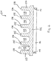
- Fig. 1 shows a channel element 01, which is made of a glass fiber reinforced thermoset in a perspective view from above.
- a channel element 01 which is made of a glass fiber reinforced thermoset in a perspective view from above.
- several channel elements 01 can be arranged one behind the other in a road surface in order to allow surface water to drain off.
- Fig. 2 shows the channel element 01 in cross section along the section line II (see Fig. 4 ).
- the channel element 01 comprises a bottom section 02 and two side walls 03 and 04. Between the side walls 03 and 04, four support webs 05 are integrally formed on the top of the bottom section 02.
- the upper end 06 of the support webs 05 runs at the height of the upper end 07 or 08 of the two side walls 03 and 04.
- the arrangement of the support elements 05 between the two side walls 03 and 04 reduces the width of the partial channels 09 formed by the side walls 03 and 04 and the support elements 05 to such an extent that the partial channels 09 are passed over by rolling on the upper ends 06, 07 and 08 is easily possible.
- stiffening ribs 10 and 11 are integrally formed on the underside of the bottom section 02. Transition radii 13 are provided at the material transition between the support webs 05 and the base section 02 in order to simplify the cleaning of the partial channels 09 and to increase the mechanical stability of the support webs 05.
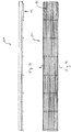
- FIG. 3 and 4 show the channel element 01 in a side view or in a view from above.
- a water drainage element 12 molded into the channel element 01, to which a water drainage connection or a water drainage pipe can be connected.
- the water drainage element 12 is initially made impermeable to water and thus contains no water-permeable recesses. Instead, there are target bore markings in the water drainage element (in 3 and 4 not shown) molded in, in order to make it easier for the user to make corresponding bores in the area of the water drainage element in the event that a channel element is to be equipped with a water drainage element. If the user has drilled through the water drainage element 12 at the predetermined bore markings, it is then water-permeable, so that the water guided in the subchannels 09 can flow downwards.
- Fig. 5 shows the channel element 01 when attached to two stand elements 14 and 15.
- a sheet metal web 16 which projects laterally on the channel element 01, is first attached from the underside of the channel element 01.
- two through bores are provided, which are penetrated by threaded rods 17.
- the groove element 01 can then be fixed on the stand elements 14 and 15 by means of fixing nuts 20.
- a cover element 21 is attached, with which the partial channels 09 of the channel element 01 are closed from above in order to prevent liquid concrete from penetrating into the partial channels 09 during pouring with concrete.
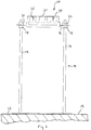
- Fig. 6 shows the channel element 01, the stand element 14 and the cover element 21 when arranged on the bare ceiling 22 of an underground car park in a side view.
- Fig. 7 shows the channel element 01, the stand element 14 and the cover element 21 after casting with concrete 23 to form a road surface 24 in cross section. It can be seen that the upper ends 06, 07 and 08 of the supporting webs 05 and the side walls 03 and 04 lie exactly at the level of the road surface 24 formed by the concrete mass 23 and can therefore be easily run over by vehicle wheels. The penetration is through the cover member 21 of liquid concrete mass 23, while smoothing the road surface 24, easily avoided.
- Clamping elements 25 are provided on the underside of the cover element 21, with which the cover element 21 can be fixed on the channel element 01. Clamping elements 25 are realized by cutting out and bending down the sheet metal material from which the cover element 21 is made.
- Fig. 8 shows the final state after installation of the channel element 01 in the concrete pavement surface 24. After removing the cover element 21, the partial channels 09 are open at the top and can easily drain off the surface water accumulating on the pavement surface 24 and thus drain the pavement surface 24 in the desired manner .
Landscapes
- Engineering & Computer Science (AREA)
- Health & Medical Sciences (AREA)
- Life Sciences & Earth Sciences (AREA)
- Hydrology & Water Resources (AREA)
- Public Health (AREA)
- Water Supply & Treatment (AREA)
- Architecture (AREA)
- Civil Engineering (AREA)
- Structural Engineering (AREA)
- Road Paving Structures (AREA)
- Sewage (AREA)
Description
Die Erfindung betrifft ein Rinnenelement zur Bildung einer im Boden verlegten und in diesem eingebetteten Entwässerungsrinne gemäß dem Oberbegriff des Anspruchs 1.The invention relates to a channel element for forming a drainage channel which is laid in the floor and embedded therein, according to the preamble of claim 1.
Derartige Rinnenelemente dienen zur Entwässerung beispielsweise von Garageneinfahrten, Stellplätzen oder Tiefgaragen. Zur Erhöhung der Flüssigkeitsaufnahmekapazität ist aus der
Derartige aus Beton hergestellte Rinnenelemente haben ein sehr großes Gewicht, so dass die Handhabung beim Verlegen und Einbetten im Untergrund relativ schwer ist. So kann beispielsweise ein 1-Meter langes Kanalelement aus Beton möglichst breit verlegt werden. Durch die relativ große Schlagempfindlichkeit der aus Beton bestehenden Rinnenelemente ist außerdem der Transport, der ohnehin in der Regel nur mit einem Lastkraftwagen erfolgen kann, zusätzlich mit einem erhöhten Beschädigungsrisiko verbunden. Ferner ergeben sich durch die Sprödigkeit der aus Beton hergestellten Rinnenelemente auch Probleme bei der Lagerung. So müssen derartige Rinnenelemente sehr vorsichtig transportiert und gelagert werden, so dass ein direktes Aufeinanderliegen und Anstoßen der Rinnenelemente möglichst vermieden wird.Such channel elements made of concrete are very heavy, so that handling when laying and embedding in the subsurface is relatively difficult. For example, a 1 meter long duct element made of concrete can be laid as wide as possible. Due to the relatively high impact sensitivity of the channel elements made of concrete, the transport, which can generally only be carried out with a truck anyway, is also associated with an increased risk of damage. Furthermore, the brittleness of the channel elements made of concrete also results in storage problems. Such channel elements must be transported and stored very carefully, so that the channel elements directly lying on top of one another and abutting are avoided as far as possible.
Durch Erhöhung der Wandstärke der Rinnenelemente kann man die Transport- und Lagerschäden zwar reduzieren, allerdings führt dieser Schritt auf der Gegenseite dazu, dass die Montage und insbesondere die Verlegearbeiten noch schwieriger werden.By increasing the wall thickness of the channel elements, you can reduce the transport and storage damage, but this step on the other side leads to the fact that the assembly and in particular the laying work are even more difficult.
Aus der
Aus der
Aus der
Die
Nachteilig an diesen metallischen Abdeckrosten ist es, dass bei der Reinigung des Rinnenelements, um beispielsweise Laub und andere Schmutzpartikel aus dem U-förmigen Kanal zu entfernen, jeweils der Abdeckrost abgenommen werden muss. Außerdem werden die Kosten für das Rinnenelement durch den zusätzlichen Abdeckrost wesentlich erhöht. Beim Transport und der Lagerung der Rinnenelemente muss außerdem streng darauf geachtet werden, dass die einzelnen Abdeckroste nicht von den jeweils zugeordneten Rinnenelementen getrennt werden.A disadvantage of these metallic cover gratings is that when cleaning the channel element, for example to remove leaves and other dirt particles from the U-shaped channel, the cover grate must be removed in each case. In addition, the costs for the channel element are significantly increased by the additional cover grate. When transporting and storing the channel elements, care must also be taken to ensure that the individual cover grids are not separated from the channel elements assigned to them.
Ausgehend von diesem Stand der Technik ist es Aufgabe der vorliegenden Erfindung, ein neues Rinnenelement zur Bildung einer Entwässerungsrinne vorzuschlagen, das die oben beschriebenen Nachteile von metallischen Abdeckrosten vermeidet.Starting from this prior art, it is an object of the present invention to propose a new channel element for forming a drainage channel, which avoids the disadvantages of metallic cover gratings described above.
Diese Aufgabe wird durch ein Rinnenelement nach der Lehre des Anspruchs 1 gelöst.This object is achieved by a channel element according to the teaching of claim 1.
Vorteilhafte Ausführungsformen der Erfindung sind Gegenstand der Unteransprüche.Advantageous embodiments of the invention are the subject of the dependent claims.
Das erfindungsgemäße Rinnenelement beruht auf dem Grundgedanken, dass am Bodenabschnitt zwischen den Seitenwandungen zumindest ein Stützsteg angeformt ist, der sich vertikal nach oben erstreckt. Das obere Ende des Stützstegs verläuft dabei im Wesentlichen in der gleichen Höhe wie das obere Ende der beiden Seitenwandungen. Durch den Stützsteg zwischen den beiden Seitenwandungen wird der freie Abstand zwischen den Seitenwandungen abhängig von der Anzahl der Stützstege halbiert, gedrittelt, geviertelt usw. Durch die signifikante Verringerung der Abstände zwischen den Seitenwandungen und den Stützstegen kann im Ergebnis auch ohne Anbringung eines Abdeckrostes eine gut befahrbare Fahrbahn an der Oberseite des Rinnenelements gebildet werden. Denn aufgrund des Durchmessers von Fahrzeugreifen ist ein freier Abstand zwischen den Seitenwandungen und den einzelnen Stützstegen von beispielsweise lediglich 10 bis 20 mm problemlos überfahrbar. Im Ergebnis wird der U-förmige Kanal des Rinnenelements durch die an der Oberseite des Bodenabschnitts angebrachten Stützstege in mehrere U-förmige Teilkanäle aufgeteilt, wobei der freie Abstand zwischen den einzelnen Teilkanälen entsprechend kleiner und damit problemlos überfahrbar ist. Um die mechanische Festigkeit des Rinnenelements zu erhöhen, werden erfindungsgemäß an der Unterseite des Bodenabschnitts eine oder mehrere Versteifungsrippen angeformt. Bei den aus dem Stand der Technik bekannten Rinnenelementen ist es üblich am Ende eines aus mehreren Rinnenelementen gebildeten Wasserablaufkanals ein weiteres spezielles Entwässerungsrinnenelement anzuordnen, das ausschließlich als Wassereinlaufzapfen dient. Die Kommissionierung, Lagerung und der Transport solcher spezieller Wasser-Einlaufkästen stellt einen hohen logistischen und damit kostenmäßigen Aufwand dar. Zur Vermeidung dieses Aufwands ist in das erfindungsgemäße Rinnenelement bereits ein Wasserablaufelement eingeformt. Soweit das jeweilige Rinnenelement keinen Wasserablauf bilden soll, wird dieses bereits angeformte Wasserablaufelement gattungsgemäß abgedichtet. Um die Abdichtung des Wasserablaufelements im Rinnenelement zu vermeiden, ist das Wasserablaufelement selbst zunächst wasserundurchlässig ausgebildet. Zudem weist das Wasserablaufelement Sollbohrungsmarkierungen auf. Soweit das einzelne Rinnenelement zugleich als Wasserablauf dienen soll, kann der Benutzer durch Anbringung entsprechender Bohrungen an den Sollbohrungsmarkierungen die Wasserundurchlässigkeit des Wasserablaufs durchbrechen und auf diese Weise problemlos das gewünschte Wasserablaufelement durch Anbringung der Bohrungen erst auf der Baustelle realisieren. Um die mechanische Festigkeit des Rinnenelements zu erhöhen, werden erfindungsgemäß an der Unterseite des Bodenabschnitts eine oder mehrere Versteifungsrippen angeformt.The channel element according to the invention is based on the basic idea that at least one support web is formed on the bottom section between the side walls and extends vertically upwards. The upper end of the support web runs essentially at the same height as the upper end of the two side walls. Due to the support web between the two side walls, the free distance between the side walls is halved, divided into three, divided into three, depending on the number of support webs Roadway are formed at the top of the channel element. Because due to the diameter of vehicle tires, a free distance between the side walls and the individual support webs of, for example, only 10 to 20 mm can be passed without problems. As a result, the U-shaped channel of the channel element is divided into a plurality of U-shaped subchannels by the support webs attached to the top of the base section, the free distance between the individual subchannels being correspondingly smaller and thus being able to be passed over without problems. In order to increase the mechanical strength of the channel element, one or more stiffening ribs are formed on the underside of the base section. In the gutter elements known from the prior art, it is customary to arrange a further special drain gutter element at the end of a water drainage channel formed from several gutter elements, which serves exclusively as a water inlet spigot. The picking, storage and transportation of such special water inlet boxes represents a high logistical and therefore costly expense. To avoid this effort, a water drainage element is already molded into the channel element according to the invention. Insofar as the respective channel element is not intended to form a water drain, this is already formed on the water drain element genetically sealed. In order to avoid sealing the water drainage element in the channel element, the water drainage element itself is initially made impermeable to water. In addition, the water drainage element has predetermined bore markings. Insofar as the individual channel element is also intended to serve as a water drain, the user can break through the water impermeability of the water drain by making appropriate bores on the predetermined bore markings and in this way can easily realize the desired water drainage element by drilling the bores only on the construction site. In order to increase the mechanical strength of the channel element, one or more stiffening ribs are formed on the underside of the base section.
Die Anzahl der zwischen den beiden Seitenwandungen angebrachten Stützstege ist letztendlich wahlweise auf den jeweiligen Anwendungsfall anpassbar, wobei der freie Abstand zwischen Seitenwandungen und den Stützstegen ein bestimmtes Maß nicht überschreiten sollte, um die Überfahrbarkeit der Oberseite des Rinnenelements zu gewährleisten. Für Rinnenelemente mit üblichen Größendimensionen hat es sich als besonders vorteilhaft erwiesen, dass zwischen den beiden Seitenwandungen vier Stützstege an den Bodenabschnitt angeformt sind. Bei einer Gesamtbreite des Rinnenelements von beispielweise 120 mm ergeben sich dabei durch die Seitenwandungen und die vier Stützstege fünf Teilkanäle mit einer Breite im Bereich zwischen 10 und 15 mm. Diese Breite der einzelnen Teilkanäle kann dann auch ohne Anbringung eines Abdeckrostes problemlos mit einem Fahrzeug überfahren werden.The number of support webs attached between the two side walls can ultimately be optionally adapted to the respective application, the free distance between the side walls and the support webs not exceeding a certain dimension in order to ensure that the top of the channel element can be driven over. For channel elements with customary size dimensions, it has proven to be particularly advantageous that four support webs are formed on the bottom section between the two side walls. With a total width of the channel element of, for example, 120 mm, the side walls and the four support webs result in five sub-channels with a width in the range between 10 and 15 mm. This width of the individual subchannels can then be easily passed over by a vehicle even without a covering grille being attached.
Um ein Ausbrechen der Stützstege bei Belastung zu vermeiden und zugleich die Reinigung der einzelnen Teilkanäle zu vereinfachen, ist es besonders vorteilhaft, wenn die Materialübergänge zwischen dem Stützsteg einerseits und dem Bodenabschnitt andererseits mit Übergangsradien ausgerundet sind.In order to prevent the supporting webs from breaking out under load and at the same time to simplify the cleaning of the individual subchannels, it is particularly advantageous if the material transitions between the supporting web on the one hand and the base section on the other hand are rounded off with transition radii.
Die erfindungsgemäßen Rinnenelemente werden vielfach in Fahrbahnoberflächen einbetoniert. Dies bedeutet, dass die Rinnenelemente baustellenseitig zunächst mit geeigneten Montagemitteln in der gewünschten Höhe angebracht und anschließend mit Beton umgossen werden. Der zunächst noch nicht ausgehärtete Beton wird dann an der Oberseite der Rinnenelemente glattgestrichen, so dass sich in der Höhe des oberen Endes der Stützstege bzw. der Seitenwandungen eine daran anschließende glatte Beton-Fahrbahnoberfläche bildet. Diese Anbringung des zunächst flüssigen Betons beim Umgießen der Rinnenelemente und insbesondere das Glattstreichen des Betons zur Bildung der betonierten Fahrbahnoberfläche wird erheblich vereinfacht, wenn an der Oberseite des Rinnenelements ein abnehmbares Abdeckelement angeordnet ist, mit dem die zwischen den Stützstegen und den Seitenwandungen gebildeten Einzelrinnen von oben verschlossen werden. Im Ergebnis wird also durch das Abdeckelement während des Eingießens der Rinnenelemente in den Beton ein unerwünschtes Eindringen des Betons in die Einzelrinnen des Rinnenelements vermieden. Sobald der Beton dann vollständig ausgehärtet ist, können die Abdeckelemente abgenommen und damit die Rinnenelemente ihrer Funktion zur Wasserabführung zugeführt werden.The channel elements according to the invention are often concreted into road surfaces. This means that the gutter elements are first installed at the desired height on the construction site and then cast in concrete. The concrete, which has not yet hardened, is then smoothed on the upper side of the channel elements, so that a smooth concrete road surface adjoins it forms at the height of the upper end of the support webs or the side walls. This application of the initially liquid concrete when pouring over the channel elements and in particular the smoothing of the concrete to form the concrete road surface is considerably simplified if a removable cover element is arranged on the top of the channel element, with which the individual channels formed between the support webs and the side walls from above be closed. As a result, an undesired penetration of the concrete into the individual channels of the channel element is avoided by the cover element during the pouring of the channel elements into the concrete. As soon as the concrete has completely hardened, the cover elements can be removed and the channel elements can thus be used for water drainage.
In welcher Weise die Abdeckelemente auf der Oberseite des Rinnenelements fixiert werden, ist grundsätzlich beliebig. Besonders einfach kann dies mittels Klemmelementen realisiert werden, die an der Unterseite des Abdeckelements angeordnet sind und an den Stützstegen bzw. an den Seitenwandungen fixierend zum Eingriff kommen.The manner in which the cover elements are fixed on the top of the channel element is fundamentally arbitrary. This can be implemented in a particularly simple manner by means of clamping elements which are arranged on the underside of the cover element and come into engagement in a fixing manner on the support webs or on the side walls.
Besonders einfach und kostengünstig kann das Abdeckelement aus Blechmaterial hergestellt werden. In diesem Fall können die Klemmelemente zur Fixierung des Abdeckelements durch entsprechendes Ausschneiden und Umbiegen des Blechmaterials problemlos in das Abdeckelement integriert werden.The cover element can be produced from sheet metal material in a particularly simple and cost-effective manner. In this case, the clamping elements for fixing the cover element can be easily integrated into the cover element by appropriately cutting out and bending the sheet metal material.
Um das Einbetonieren des Rinnenelements zu ermöglichen, müssen die Rinnenelemente vor dem Ausbringen des Betons mit geeigneten Montagemitteln in der gewünschten Höhe vorfixiert werden. Um dies in einfacher Weise zu realisieren ist es besonders vorteilhaft, wenn an der Unterseite des Bodenabschnitts zumindest ein Ständerelement befestigbar ist. Das Ständerelement selbst kann dann auf der Oberseite des jeweiligen Baukörpers, beispielsweise der Rohdecke einer Tiefgarage, angebracht werden. Durch das Ständerelement selbst wird dann eine vorgegebene Einbauhöhe des Rinnenelements über dem Baukörper gesichert. Sobald alle Rinnenelemente an dem Baukörper in dieser Weise vorfixiert sind, können die Zwischenräume zwischen den Baukörpern und den Rinnenelementen mit Beton ausgegossen, und dadurch die Fahrbahnoberfläche gebildet und die Rinnenelemente in der Fahrbahn fixiert werden.In order to enable the channel element to be concreted in, the channel elements must be fitted with suitable assembly means before the concrete is applied be pre-fixed at the desired height. In order to achieve this in a simple manner, it is particularly advantageous if at least one stand element can be attached to the underside of the base section. The stand element itself can then be attached to the top of the respective structure, for example the raw ceiling of an underground car park. A predetermined installation height of the channel element is then secured above the structure by the stand element itself. As soon as all channel elements have been pre-fixed to the structure in this way, the gaps between the structure and the channel elements can be poured with concrete, thereby forming the road surface and fixing the channel elements in the road.
Die Oberseite der Rinnenelemente definiert die Höhe der später beim Betonieren der Fahrbahn gebildeten Fahrbahnoberfläche. Um die einzelnen Rinnenelemente gemäß dem gewünschten Höhenniveau einfach ausrichten zu können, ist es besonders vorteilhaft, wenn das Ständerelement eine Einstelleinrichtung umfasst, mit der die Einbauhöhe des Rinnenelements über den Baukörper, bei Anbringung des Ständerelements zwischen dem Baukörper und dem Rinnenelement, einstellbar ist.The top of the channel elements defines the height of the road surface that will be formed later when the roadway is concreted. In order to be able to easily align the individual channel elements according to the desired height level, it is particularly advantageous if the stand element comprises an adjusting device with which the installation height of the channel element can be adjusted above the structure when the column element is attached between the structure and the channel element.
In welcher konstruktiven Art die Einstelleinrichtung ausgebildet ist, ist grundsätzlich beliebig. Besonders einfach und kostengünstig kann die Einstelleinrichtung in der Art eines Einstellgewindes ausgebildet sein. Durch Anbringung und Einstellung von Stellmuttern kann dann die Einbauhöhe des Rinnenelements problemlos variiert und fixiert werden.It is fundamentally arbitrary in which construction the adjustment device is designed. The adjusting device can be designed in the manner of an adjusting thread in a particularly simple and inexpensive manner. The installation height of the channel element can then be easily varied and fixed by attaching and adjusting adjusting nuts.
Aus welchem Kunststoff die Rinnenelemente hergestellt sind, ist grundsätzlich beliebig. Eine besonders hohe Stabilität und Haltbarkeit ergibt sich, wenn die Rinnenelemente aus einem Duroplast hergestellt sind. Um eine besonders hohe mechanische Festigkeit zu realisieren, ist es vorteilhaft wenn in den Kunststoff, aus dem die Rinnenelemente gebildet sind, Verstärkungsfasern, insbesondere Glasfasern, eingebettet sind. So können die erfindungsgemäßen Rinnenelemente besonders einfach und kostengünstig und mechanisch hochstabil aus vorgefertigten Duroplast-Prepregs produziert werden. Die Duroplast-Prepregs, die bereits die gewünschte Menge an Glasfasern enthalten, werden dazu in eine geeignete Pressform eingebracht und dort nach Ausbildung der gewünschten Geometrie des Rinnenelements unter Hitze ausgehärtet.The plastic from which the channel elements are made is basically arbitrary. A particularly high stability and durability results if the channel elements are made of a thermoset. In order to achieve a particularly high mechanical strength, it is advantageous if reinforcing fibers, in particular glass fibers, are embedded in the plastic from which the channel elements are formed. The channel elements according to the invention can be particularly simple and can be produced inexpensively and mechanically highly stable from prefabricated thermoset prepregs. For this purpose, the thermoset prepregs, which already contain the desired amount of glass fibers, are placed in a suitable press mold and cured there under heat after the desired geometry of the channel element has been formed.
Eine Ausführungsform der Erfindung ist in den Zeichnungen schematisch dargestellt und wird nachfolgend beispielhaft erläutert.An embodiment of the invention is shown schematically in the drawings and is explained below by way of example.
Es zeigen:
- Fig. 1
- ein erfindungsgemäßes Rinnenelement in perspektivischer Ansicht von oben;
- Fig. 2
- das Rinnenelement gemäß
Fig. 1 im Querschnitt; - Fig. 3
- das Rinnenelement gemäß
Fig. 1 in seitlicher Ansicht; - Fig. 4
- das Rinnenelement gemäß
Fig. 1 in Ansicht von oben; - Fig. 5
- das Rinnenelement gemäß
Fig. 1 bei Montage auf zwei Ständerelementen und bei Abdeckung in einem Abdeckelement in perspektivischer Ansicht von oben; - Fig. 6
- das Rinnenelement und die Ständerelemente und das Abdeckelement gemäß
Fig. 5 in seitlicher Ansicht; - Fig. 7
- das Rinnenelement, das Ständerelement und das Abdeckelement gemäß
Fig. 6 nach der Bildung einer Fahrbahnoberfläche durch Ausgießen mit Beton im Querschnitt; - Fig. 8
- das Rinnenelement und das Ständerelement gemäß
Fig. 7 nach Abnehmen des Abdeckelements zur Bildung der fertigen Fahrbahnoberfläche.
- Fig. 1
- a channel element according to the invention in a perspective view from above;
- Fig. 2
- the gutter element according to
Fig. 1 in cross section; - Fig. 3
- the gutter element according to
Fig. 1 in a side view; - Fig. 4
- the gutter element according to
Fig. 1 in top view; - Fig. 5
- the gutter element according to
Fig. 1 when mounted on two stand elements and when covered in a cover element in a perspective view from above; - Fig. 6
- the channel element and the stand elements and the cover element according to
Fig. 5 in a side view; - Fig. 7
- the channel element, the stand element and the cover element according to
Fig. 6 after the formation of a road surface by pouring concrete in cross section; - Fig. 8
- the channel element and the stand element according to
Fig. 7 after removing the cover element to form the finished road surface.
Claims (11)
- A channel element (01) for forming a drainage channel laid in a roadway and embedded in the ground across the entire height, the channel element comprising a substantially U-shaped conduit having a horizontal base section (02) and two vertical side walls (03, 04) moulded onto the sides of the base section (02), and at least one support web (05) which extends vertically upwards being moulded onto the base section (02) between the side walls (03, 04), and the upper end (06) of the support web (05) running substantially at the same height as the upper end of the two side walls (03, 04), and the channel element (01) being made of plastic,characterised in thata water drain element (12) is moulded into the channel element (01), the water drain element (12) being impermeable to water and having predetermined drill hole markings and stiffening ribs (10, 11) being moulded onto the bottom side of the base section (02).
- The channel element according to claim 1,characterised in thatseveral, in particular four, support webs (05) are moulded onto the base section (02) between the side walls (03, 04).
- The channel element according to claim 1 or 2,characterised in thattransition radii (13) are provided at the material transitions between the support web (05) and the base section (02).
- The channel element according to any one of claims 1 to 3,characterised in thata removable cover element (21) is disposed on the upper side of the channel element (01), by means of which (21) the sub-conduits (09) formed between the support webs (05) and the side walls (03, 04) are closed from above.
- The channel element according to claim 4,characterised in thatthe cover element (21) is fixed to the support webs (05) and/or to the side walls (03, 04) by means of clamping elements (25).
- The channel element according to claim 4 or 5,characterised in thatthe cover element (21) is made of sheet metal material.
- The channel element according to any one of claims 1 to 6,characterised in thatat least one post element (14, 15) is fixed to the bottom side of the base section (02), the post element (14, 15) being disposed on a structure (22), and the post element (14, 15) securing a predetermined installation height of the channel element (01) above the structure (22).
- The channel element according to claim 7,characterised in thatthe post element (14, 15) comprises an adjusting means by means of which the installation height of the channel element (01) above the structure (22) is adjusted.
- The channel element according to claim 8,characterised in thatthe adjusting means is formed in the manner of an adjusting thread at which the installation height of the channel element (01) is fixed by means of adjusting nuts (18).
- The channel element according to any one of claims 1 to 9,
characterised in that
the plastic for forming the channel element (01) is composed of a thermosetting resin. - The channel element according to claims 1 to 10,
characterised in that
reinforcing fibres, in particular glass fibres, are embedded into the plastic which forms the channel element (01).
Applications Claiming Priority (1)
| Application Number | Priority Date | Filing Date | Title |
|---|---|---|---|
| DE202017101169.0U DE202017101169U1 (en) | 2017-03-02 | 2017-03-02 | Channel element for forming a drainage channel |
Publications (2)
| Publication Number | Publication Date |
|---|---|
| EP3369862A1 EP3369862A1 (en) | 2018-09-05 |
| EP3369862B1 true EP3369862B1 (en) | 2020-04-15 |
Family
ID=58722152
Family Applications (1)
| Application Number | Title | Priority Date | Filing Date |
|---|---|---|---|
| EP18158028.3A Active EP3369862B1 (en) | 2017-03-02 | 2018-02-22 | Gutter element for forming a drainage channel |
Country Status (2)
| Country | Link |
|---|---|
| EP (1) | EP3369862B1 (en) |
| DE (1) | DE202017101169U1 (en) |
Families Citing this family (1)
| Publication number | Priority date | Publication date | Assignee | Title |
|---|---|---|---|---|
| DE102023108011A1 (en) | 2023-03-29 | 2024-10-02 | Friedrich Wolfarth Gmbh & Co. Kg | fastening device for a gutter element |
Family Cites Families (7)
| Publication number | Priority date | Publication date | Assignee | Title |
|---|---|---|---|---|
| DE8220949U1 (en) | 1982-07-22 | 1982-10-28 | M.Meisinger KG, 8890 Aichach | GUTTER ELEMENT FOR A DRAINAGE GUTTER |
| US4993877A (en) * | 1987-10-02 | 1991-02-19 | Construction Casting Company | Method and apparatus for forming a trench |
| DE29700391U1 (en) * | 1997-01-13 | 1998-05-07 | HYDROTEC Entwässerungstechnik GmbH & Co. KG, 27793 Wildeshausen | Drainage channel |
| DE10335505A1 (en) * | 2003-07-31 | 2005-02-24 | Mea Meisinger Ag | Drainage element and use of a drainage element |
| DE202009016877U1 (en) * | 2009-12-15 | 2010-03-11 | Hydrotec Technologies Ag | Drainage channel element |
| ITBO20130219A1 (en) * | 2013-05-14 | 2014-11-15 | Redi S P A Con Socio Unico | DRAINAGE SYSTEM FOR ROAD FLOORS |
| DE202016105078U1 (en) * | 2016-09-13 | 2016-10-27 | Graspointner Holding Gmbh | Drainage element and modular system |
-
2017
- 2017-03-02 DE DE202017101169.0U patent/DE202017101169U1/en active Active
-
2018
- 2018-02-22 EP EP18158028.3A patent/EP3369862B1/en active Active
Non-Patent Citations (1)
| Title |
|---|
| None * |
Also Published As
| Publication number | Publication date |
|---|---|
| DE202017101169U1 (en) | 2017-05-02 |
| EP3369862A1 (en) | 2018-09-05 |
Similar Documents
| Publication | Publication Date | Title |
|---|---|---|
| EP2851477B1 (en) | Drainage gutter | |
| WO2001094704A1 (en) | Cover piece for a drainage channel | |
| EP3369862B1 (en) | Gutter element for forming a drainage channel | |
| DE102008049966C5 (en) | Connection for a traffic control wall | |
| DE60317611T2 (en) | Wide drainage channel | |
| DE202006020230U1 (en) | Drainage device for draining liquids from traffic areas in road construction | |
| DE202012102396U1 (en) | Joint profile and arrangement of several joint profiles for joints in a concrete pavement | |
| DE102005029648A1 (en) | Balcony frame and method for manufacturing a precast balcony | |
| EP2188459B1 (en) | Drainage channel | |
| EP1857592A1 (en) | Method of forming a drainage unit for a road surface and a drainage unit for draining of a road surface | |
| DE102007017612A1 (en) | Frame for a balcony or a terrace and method for its production | |
| DE8220949U1 (en) | GUTTER ELEMENT FOR A DRAINAGE GUTTER | |
| EP0952252A1 (en) | Shuttering for embedding a rail | |
| DE202011104877U1 (en) | Drainage gutter system | |
| DE102013207951A1 (en) | Drainage system for a traffic area | |
| AT513278B1 (en) | Flume for the removal of surface water | |
| DE102023108011A1 (en) | fastening device for a gutter element | |
| WO2009147586A1 (en) | Traffic guidance device | |
| DE19847672C1 (en) | One-piece drainage component for installation beneath edge area of road surface has load accommodation points, which define locating surface on one side of component | |
| DE202017105401U1 (en) | Semi-finished track and track with at least one ready-made track | |
| AT520609B1 (en) | Drainage device for draining a subsoil | |
| DE2703583A1 (en) | Drain built flush into road or runway surface - has U=section gutter piece and cover plate joined together by adhesive layers or anchors | |
| DE2263371A1 (en) | DEVICE FOR FASTENING PRECAST CONCRETE PART | |
| DE202019100754U1 (en) | Channel element for forming a drainage channel | |
| DE8809408U1 (en) | Gutter element for drainage systems |
Legal Events
| Date | Code | Title | Description |
|---|---|---|---|
| PUAI | Public reference made under article 153(3) epc to a published international application that has entered the european phase |
Free format text: ORIGINAL CODE: 0009012 |
|
| STAA | Information on the status of an ep patent application or granted ep patent |
Free format text: STATUS: THE APPLICATION HAS BEEN PUBLISHED |
|
| AK | Designated contracting states |
Kind code of ref document: A1 Designated state(s): AL AT BE BG CH CY CZ DE DK EE ES FI FR GB GR HR HU IE IS IT LI LT LU LV MC MK MT NL NO PL PT RO RS SE SI SK SM TR |
|
| AX | Request for extension of the european patent |
Extension state: BA ME |
|
| STAA | Information on the status of an ep patent application or granted ep patent |
Free format text: STATUS: REQUEST FOR EXAMINATION WAS MADE |
|
| 17P | Request for examination filed |
Effective date: 20181123 |
|
| RBV | Designated contracting states (corrected) |
Designated state(s): AL AT BE BG CH CY CZ DE DK EE ES FI FR GB GR HR HU IE IS IT LI LT LU LV MC MK MT NL NO PL PT RO RS SE SI SK SM TR |
|
| RIN1 | Information on inventor provided before grant (corrected) |
Inventor name: WOLFARTH, ULRICH |
|
| RIN1 | Information on inventor provided before grant (corrected) |
Inventor name: WOLFARTH, ULRICH |
|
| GRAP | Despatch of communication of intention to grant a patent |
Free format text: ORIGINAL CODE: EPIDOSNIGR1 |
|
| STAA | Information on the status of an ep patent application or granted ep patent |
Free format text: STATUS: GRANT OF PATENT IS INTENDED |
|
| INTG | Intention to grant announced |
Effective date: 20191206 |
|
| GRAS | Grant fee paid |
Free format text: ORIGINAL CODE: EPIDOSNIGR3 |
|
| GRAA | (expected) grant |
Free format text: ORIGINAL CODE: 0009210 |
|
| STAA | Information on the status of an ep patent application or granted ep patent |
Free format text: STATUS: THE PATENT HAS BEEN GRANTED |
|
| AK | Designated contracting states |
Kind code of ref document: B1 Designated state(s): AL AT BE BG CH CY CZ DE DK EE ES FI FR GB GR HR HU IE IS IT LI LT LU LV MC MK MT NL NO PL PT RO RS SE SI SK SM TR |
|
| REG | Reference to a national code |
Ref country code: CH Ref legal event code: EP |
|
| REG | Reference to a national code |
Ref country code: DE Ref legal event code: R096 Ref document number: 502018001171 Country of ref document: DE |
|
| REG | Reference to a national code |
Ref country code: IE Ref legal event code: FG4D Free format text: LANGUAGE OF EP DOCUMENT: GERMAN |
|
| REG | Reference to a national code |
Ref country code: AT Ref legal event code: REF Ref document number: 1257420 Country of ref document: AT Kind code of ref document: T Effective date: 20200515 |
|
| REG | Reference to a national code |
Ref country code: CH Ref legal event code: NV Representative=s name: BODENSEEPATENT PATENTANWAELTE BEHRMANN WAGNER , CH |
|
| REG | Reference to a national code |
Ref country code: NL Ref legal event code: MP Effective date: 20200415 |
|
| REG | Reference to a national code |
Ref country code: LT Ref legal event code: MG4D |
|
| PG25 | Lapsed in a contracting state [announced via postgrant information from national office to epo] |
Ref country code: FI Free format text: LAPSE BECAUSE OF FAILURE TO SUBMIT A TRANSLATION OF THE DESCRIPTION OR TO PAY THE FEE WITHIN THE PRESCRIBED TIME-LIMIT Effective date: 20200415 Ref country code: NO Free format text: LAPSE BECAUSE OF FAILURE TO SUBMIT A TRANSLATION OF THE DESCRIPTION OR TO PAY THE FEE WITHIN THE PRESCRIBED TIME-LIMIT Effective date: 20200715 Ref country code: SE Free format text: LAPSE BECAUSE OF FAILURE TO SUBMIT A TRANSLATION OF THE DESCRIPTION OR TO PAY THE FEE WITHIN THE PRESCRIBED TIME-LIMIT Effective date: 20200415 Ref country code: NL Free format text: LAPSE BECAUSE OF FAILURE TO SUBMIT A TRANSLATION OF THE DESCRIPTION OR TO PAY THE FEE WITHIN THE PRESCRIBED TIME-LIMIT Effective date: 20200415 Ref country code: LT Free format text: LAPSE BECAUSE OF FAILURE TO SUBMIT A TRANSLATION OF THE DESCRIPTION OR TO PAY THE FEE WITHIN THE PRESCRIBED TIME-LIMIT Effective date: 20200415 Ref country code: PT Free format text: LAPSE BECAUSE OF FAILURE TO SUBMIT A TRANSLATION OF THE DESCRIPTION OR TO PAY THE FEE WITHIN THE PRESCRIBED TIME-LIMIT Effective date: 20200817 Ref country code: GR Free format text: LAPSE BECAUSE OF FAILURE TO SUBMIT A TRANSLATION OF THE DESCRIPTION OR TO PAY THE FEE WITHIN THE PRESCRIBED TIME-LIMIT Effective date: 20200716 Ref country code: IS Free format text: LAPSE BECAUSE OF FAILURE TO SUBMIT A TRANSLATION OF THE DESCRIPTION OR TO PAY THE FEE WITHIN THE PRESCRIBED TIME-LIMIT Effective date: 20200815 |
|
| PG25 | Lapsed in a contracting state [announced via postgrant information from national office to epo] |
Ref country code: RS Free format text: LAPSE BECAUSE OF FAILURE TO SUBMIT A TRANSLATION OF THE DESCRIPTION OR TO PAY THE FEE WITHIN THE PRESCRIBED TIME-LIMIT Effective date: 20200415 Ref country code: LV Free format text: LAPSE BECAUSE OF FAILURE TO SUBMIT A TRANSLATION OF THE DESCRIPTION OR TO PAY THE FEE WITHIN THE PRESCRIBED TIME-LIMIT Effective date: 20200415 Ref country code: HR Free format text: LAPSE BECAUSE OF FAILURE TO SUBMIT A TRANSLATION OF THE DESCRIPTION OR TO PAY THE FEE WITHIN THE PRESCRIBED TIME-LIMIT Effective date: 20200415 Ref country code: BG Free format text: LAPSE BECAUSE OF FAILURE TO SUBMIT A TRANSLATION OF THE DESCRIPTION OR TO PAY THE FEE WITHIN THE PRESCRIBED TIME-LIMIT Effective date: 20200715 |
|
| PG25 | Lapsed in a contracting state [announced via postgrant information from national office to epo] |
Ref country code: AL Free format text: LAPSE BECAUSE OF FAILURE TO SUBMIT A TRANSLATION OF THE DESCRIPTION OR TO PAY THE FEE WITHIN THE PRESCRIBED TIME-LIMIT Effective date: 20200415 |
|
| REG | Reference to a national code |
Ref country code: DE Ref legal event code: R097 Ref document number: 502018001171 Country of ref document: DE |
|
| PG25 | Lapsed in a contracting state [announced via postgrant information from national office to epo] |
Ref country code: DK Free format text: LAPSE BECAUSE OF FAILURE TO SUBMIT A TRANSLATION OF THE DESCRIPTION OR TO PAY THE FEE WITHIN THE PRESCRIBED TIME-LIMIT Effective date: 20200415 Ref country code: EE Free format text: LAPSE BECAUSE OF FAILURE TO SUBMIT A TRANSLATION OF THE DESCRIPTION OR TO PAY THE FEE WITHIN THE PRESCRIBED TIME-LIMIT Effective date: 20200415 Ref country code: SM Free format text: LAPSE BECAUSE OF FAILURE TO SUBMIT A TRANSLATION OF THE DESCRIPTION OR TO PAY THE FEE WITHIN THE PRESCRIBED TIME-LIMIT Effective date: 20200415 Ref country code: CZ Free format text: LAPSE BECAUSE OF FAILURE TO SUBMIT A TRANSLATION OF THE DESCRIPTION OR TO PAY THE FEE WITHIN THE PRESCRIBED TIME-LIMIT Effective date: 20200415 Ref country code: RO Free format text: LAPSE BECAUSE OF FAILURE TO SUBMIT A TRANSLATION OF THE DESCRIPTION OR TO PAY THE FEE WITHIN THE PRESCRIBED TIME-LIMIT Effective date: 20200415 Ref country code: IT Free format text: LAPSE BECAUSE OF FAILURE TO SUBMIT A TRANSLATION OF THE DESCRIPTION OR TO PAY THE FEE WITHIN THE PRESCRIBED TIME-LIMIT Effective date: 20200415 Ref country code: ES Free format text: LAPSE BECAUSE OF FAILURE TO SUBMIT A TRANSLATION OF THE DESCRIPTION OR TO PAY THE FEE WITHIN THE PRESCRIBED TIME-LIMIT Effective date: 20200415 |
|
| PLBE | No opposition filed within time limit |
Free format text: ORIGINAL CODE: 0009261 |
|
| STAA | Information on the status of an ep patent application or granted ep patent |
Free format text: STATUS: NO OPPOSITION FILED WITHIN TIME LIMIT |
|
| PG25 | Lapsed in a contracting state [announced via postgrant information from national office to epo] |
Ref country code: PL Free format text: LAPSE BECAUSE OF FAILURE TO SUBMIT A TRANSLATION OF THE DESCRIPTION OR TO PAY THE FEE WITHIN THE PRESCRIBED TIME-LIMIT Effective date: 20200415 Ref country code: SK Free format text: LAPSE BECAUSE OF FAILURE TO SUBMIT A TRANSLATION OF THE DESCRIPTION OR TO PAY THE FEE WITHIN THE PRESCRIBED TIME-LIMIT Effective date: 20200415 |
|
| REG | Reference to a national code |
Ref country code: CH Ref legal event code: PFA Owner name: FRIEDRICH WOLFARTH GMBH AND CO. KG, DE Free format text: FORMER OWNER: FRIEDRICH WOLFARTH GMBH AND CO. KG, DE |
|
| 26N | No opposition filed |
Effective date: 20210118 |
|
| PG25 | Lapsed in a contracting state [announced via postgrant information from national office to epo] |
Ref country code: SI Free format text: LAPSE BECAUSE OF FAILURE TO SUBMIT A TRANSLATION OF THE DESCRIPTION OR TO PAY THE FEE WITHIN THE PRESCRIBED TIME-LIMIT Effective date: 20200415 |
|
| PG25 | Lapsed in a contracting state [announced via postgrant information from national office to epo] |
Ref country code: MC Free format text: LAPSE BECAUSE OF FAILURE TO SUBMIT A TRANSLATION OF THE DESCRIPTION OR TO PAY THE FEE WITHIN THE PRESCRIBED TIME-LIMIT Effective date: 20200415 |
|
| REG | Reference to a national code |
Ref country code: BE Ref legal event code: MM Effective date: 20210228 |
|
| PG25 | Lapsed in a contracting state [announced via postgrant information from national office to epo] |
Ref country code: LU Free format text: LAPSE BECAUSE OF NON-PAYMENT OF DUE FEES Effective date: 20210222 |
|
| PG25 | Lapsed in a contracting state [announced via postgrant information from national office to epo] |
Ref country code: FR Free format text: LAPSE BECAUSE OF NON-PAYMENT OF DUE FEES Effective date: 20210228 Ref country code: IE Free format text: LAPSE BECAUSE OF NON-PAYMENT OF DUE FEES Effective date: 20210222 |
|
| PG25 | Lapsed in a contracting state [announced via postgrant information from national office to epo] |
Ref country code: BE Free format text: LAPSE BECAUSE OF NON-PAYMENT OF DUE FEES Effective date: 20210228 |
|
| GBPC | Gb: european patent ceased through non-payment of renewal fee |
Effective date: 20220222 |
|
| PG25 | Lapsed in a contracting state [announced via postgrant information from national office to epo] |
Ref country code: GB Free format text: LAPSE BECAUSE OF NON-PAYMENT OF DUE FEES Effective date: 20220222 |
|
| PG25 | Lapsed in a contracting state [announced via postgrant information from national office to epo] |
Ref country code: CY Free format text: LAPSE BECAUSE OF FAILURE TO SUBMIT A TRANSLATION OF THE DESCRIPTION OR TO PAY THE FEE WITHIN THE PRESCRIBED TIME-LIMIT Effective date: 20200415 |
|
| P01 | Opt-out of the competence of the unified patent court (upc) registered |
Effective date: 20230529 |
|
| PG25 | Lapsed in a contracting state [announced via postgrant information from national office to epo] |
Ref country code: HU Free format text: LAPSE BECAUSE OF FAILURE TO SUBMIT A TRANSLATION OF THE DESCRIPTION OR TO PAY THE FEE WITHIN THE PRESCRIBED TIME-LIMIT; INVALID AB INITIO Effective date: 20180222 |
|
| PGFP | Annual fee paid to national office [announced via postgrant information from national office to epo] |
Ref country code: AT Payment date: 20240216 Year of fee payment: 7 |
|
| PG25 | Lapsed in a contracting state [announced via postgrant information from national office to epo] |
Ref country code: MK Free format text: LAPSE BECAUSE OF FAILURE TO SUBMIT A TRANSLATION OF THE DESCRIPTION OR TO PAY THE FEE WITHIN THE PRESCRIBED TIME-LIMIT Effective date: 20200415 |
|
| PGFP | Annual fee paid to national office [announced via postgrant information from national office to epo] |
Ref country code: CH Payment date: 20240301 Year of fee payment: 7 |
|
| PGFP | Annual fee paid to national office [announced via postgrant information from national office to epo] |
Ref country code: DE Payment date: 20240423 Year of fee payment: 7 |
|
| PG25 | Lapsed in a contracting state [announced via postgrant information from national office to epo] |
Ref country code: MT Free format text: LAPSE BECAUSE OF FAILURE TO SUBMIT A TRANSLATION OF THE DESCRIPTION OR TO PAY THE FEE WITHIN THE PRESCRIBED TIME-LIMIT Effective date: 20200415 |