EP3369861A1 - Vorrichtung zur anordnung einer zugsicherungskomponente in einem gleisbereich - Google Patents
Vorrichtung zur anordnung einer zugsicherungskomponente in einem gleisbereich Download PDFInfo
- Publication number
- EP3369861A1 EP3369861A1 EP17159212.4A EP17159212A EP3369861A1 EP 3369861 A1 EP3369861 A1 EP 3369861A1 EP 17159212 A EP17159212 A EP 17159212A EP 3369861 A1 EP3369861 A1 EP 3369861A1
- Authority
- EP
- European Patent Office
- Prior art keywords
- cover plate
- elements
- train
- securing component
- floor rails
- Prior art date
- Legal status (The legal status is an assumption and is not a legal conclusion. Google has not performed a legal analysis and makes no representation as to the accuracy of the status listed.)
- Granted
Links
Images

Classifications
-
- E—FIXED CONSTRUCTIONS
- E01—CONSTRUCTION OF ROADS, RAILWAYS, OR BRIDGES
- E01B—PERMANENT WAY; PERMANENT-WAY TOOLS; MACHINES FOR MAKING RAILWAYS OF ALL KINDS
- E01B26/00—Tracks or track components not covered by any one of the preceding groups
-
- B—PERFORMING OPERATIONS; TRANSPORTING
- B61—RAILWAYS
- B61L—GUIDING RAILWAY TRAFFIC; ENSURING THE SAFETY OF RAILWAY TRAFFIC
- B61L3/00—Devices along the route for controlling devices on the vehicle or train, e.g. to release brake or to operate a warning signal
- B61L3/02—Devices along the route for controlling devices on the vehicle or train, e.g. to release brake or to operate a warning signal at selected places along the route, e.g. intermittent control simultaneous mechanical and electrical control
- B61L3/08—Devices along the route for controlling devices on the vehicle or train, e.g. to release brake or to operate a warning signal at selected places along the route, e.g. intermittent control simultaneous mechanical and electrical control controlling electrically
- B61L3/12—Devices along the route for controlling devices on the vehicle or train, e.g. to release brake or to operate a warning signal at selected places along the route, e.g. intermittent control simultaneous mechanical and electrical control controlling electrically using magnetic or electrostatic induction; using radio waves
- B61L3/121—Devices along the route for controlling devices on the vehicle or train, e.g. to release brake or to operate a warning signal at selected places along the route, e.g. intermittent control simultaneous mechanical and electrical control controlling electrically using magnetic or electrostatic induction; using radio waves using magnetic induction
-
- B—PERFORMING OPERATIONS; TRANSPORTING
- B61—RAILWAYS
- B61L—GUIDING RAILWAY TRAFFIC; ENSURING THE SAFETY OF RAILWAY TRAFFIC
- B61L3/00—Devices along the route for controlling devices on the vehicle or train, e.g. to release brake or to operate a warning signal
- B61L3/02—Devices along the route for controlling devices on the vehicle or train, e.g. to release brake or to operate a warning signal at selected places along the route, e.g. intermittent control simultaneous mechanical and electrical control
- B61L3/08—Devices along the route for controlling devices on the vehicle or train, e.g. to release brake or to operate a warning signal at selected places along the route, e.g. intermittent control simultaneous mechanical and electrical control controlling electrically
- B61L3/12—Devices along the route for controlling devices on the vehicle or train, e.g. to release brake or to operate a warning signal at selected places along the route, e.g. intermittent control simultaneous mechanical and electrical control controlling electrically using magnetic or electrostatic induction; using radio waves
- B61L3/126—Constructional details
-
- B—PERFORMING OPERATIONS; TRANSPORTING
- B61—RAILWAYS
- B61L—GUIDING RAILWAY TRAFFIC; ENSURING THE SAFETY OF RAILWAY TRAFFIC
- B61L27/00—Central railway traffic control systems; Trackside control; Communication systems specially adapted therefor
- B61L27/20—Trackside control of safe travel of vehicle or train, e.g. braking curve calculation
- B61L2027/202—Trackside control of safe travel of vehicle or train, e.g. braking curve calculation using European Train Control System [ETCS]
Definitions
- the present invention relates to a device for arranging a train protection component, in particular a balise, between two floor rails in a track area.
- Train protection components such as balise, track magnets, loop cables, are used in railway traffic to radio safety-relevant information on a rail vehicle or to receive from this.
- Train protection components are thus, as a rule, in the actual sense electromagnetic transmitting and receiving transponders, which are arranged in the track area between the two floor rails of the track.
- the train control components When the track is carried by sleepers, the train control components are typically placed in a so-called sleeper compartment between two sleepers. In the case of a fixed carriageway, the train protection component is accordingly fastened directly on the floor of the carriageway.
- ETCS European Train Control System
- the present invention is therefore based on the object of specifying a device for arranging a train protection component, in particular a balise, between two floor rails in a track area, in which the train control component is significantly better protected against damage during snow removal.
- the device to safely protect the train protection component against damage during snow removal.
- the cover plate By attaching the cover plate to the floor rails and / or the threshold bodies and the cover plate arranged on the underside of the insertion element, the train protection component is also held in a predeterminable position relative to the track.
- the cover plate has openings.
- These breakthroughs can be called round holes or be realized as a grid.
- the size of these breakthroughs can also be dimensioned so that a manual or automatic Gleisstippung the track ballast is possible up close to the train control component.
- the cover plate can be made of a material that is transparent to alternating electric and magnetic fields.
- the cover can be made for example of a glass fiber reinforced plastic or polymer concrete.
- the holding elements can preferably be designed so that a shielding plate can be inserted between the tension-securing component and the underside of the cover plate.
- the rail vehicle can not receive the data telegrams sent by the train protection component, which also applies in the reverse direction.
- the cover plate is bent at its edges at least partially in the direction of its bottom.
- the device is particularly useful when the train protection component is a balise.
- FIG. 1 schematically shows a plan view of a track 2 with two each mounted under a cover plate 4, 6 balises 8, 10 (see. FIG. 2 ).
- the cover plates 4, 6 rest on threshold body 12, which also carry the two floor rails 14, 16 of the track 2.
- four mounting elements 18a to 18d are provided per cover plate 4, 6, with which the cover plate is fastened to the rail foot of the floor rails 14, 16. It would also be conceivable to fasten the cover plates 4, 6 alternatively or additionally directly on the threshold bodies 12.
- the cover plates 4, 6, as in FIG. 2 better seen, as holding elements designed insertion elements 20a, 20b, which are designed in this embodiment U-shaped, so that the balises 8, 10 are easily inserted into these insertion elements 20a, 20b.
- a connecting line 22 is additionally shown schematically.
- 24 fasteners are symbolized with circular emphasis, which serve for symmetrical and asymmetrical attachment of the balise 8, 10 on the insertion elements 20 a, 20 b and / or on the cover plate 4, 6.
- the circular highlighting 24 can also represent holes in the pan head screws are screwed, so that even with fixed Balise the screw heads do not protrude over the Switzerland town aligned surface of the cover plates 4, 6.
- the cover plates 4, 6 are slightly bent downwards at their ends 26a, 26b projecting beyond the outer sleeper bodies, so as to offer the snow removing tools as little as possible an attack surface.
- the cover plate 4, 6 is made of a material that is transparent to alternating electrical and magnetic fields.
- the cover plates were manufactured as a grating made of a glass fiber reinforced plastic. It would also be conceivable to manufacture the cover plates from a polymer concrete. In particular, the latter material would also allow a modification not shown here in that the balises 8, 10 are arranged under the cover plate in a balancing box designed as a holding element, wherein the cover plate and / or the Balisenkasten connected to the floor rails and / or the threshold bodies be used to position the balises in a desired position relative to the track.
- the insertion elements 20a, 20b would then be designed as a drawer in this case.
- the closed Balkenkasten with the cover plate in the sleeper between two threshold bodies, the Bassenkasten then loose, but due to its weight still comes to rest in a recess of the ballast.
- the upper edge of the cover plate is aligned so that it is at the maximum level of the upper edge of the threshold body, but preferably lower.
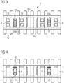
- FIG. 3 now shows a view from below, are used in the slightly modified cover plates 4 ', 6' and slightly modified insertion elements 20a 'and 20b'. While the former now have openings 28 (for example, for manual or mechanical plugging of the track ballast), the latter are now designed as two rails (similar to the telescopic rails used for cabinet drawers). Accordingly, the FIG. 4 again modified insertion elements on.
- a spacer 30, which abuts a fixed stop 31, and two movable stopper piece 32 is used to accurately position the Balise 8, 10 in its asymmetrical position in a slot from the other side.
- the insertion elements can be configured in such a way that, generally speaking, a shielding plate can be inserted between the tension-securing component and the underside of the cover plate.
Landscapes
- Engineering & Computer Science (AREA)
- Mechanical Engineering (AREA)
- Architecture (AREA)
- Civil Engineering (AREA)
- Structural Engineering (AREA)
- Train Traffic Observation, Control, And Security (AREA)
Abstract
a) eine Abdeckplatte (4, 4', 6, 6');
b) eine Anzahl von Montageelementen (18a bis 18d), mit denen die Abdeckplatte (4, 4', 6, 6') an den Stockschienen (14, 16) oder an die Stockschienen (14, 16) tragenden Schwellenkörpern (12) befestigbar ist;
c) auf der Unterseite der Abdeckplatte (4, 4', 6, 6') angeordnete Halteelemente, insbesondere Einschubelemente (20a, 20a', 20b, 20b'), in denen die Zugsicherungskomponente (8, 10) aufnehmbar ist; und
d) Befestigungselemente (24) zur Befestigung der Zugsicherungskomponente (8, 10) an den Halteelementen (20a, 20a', 20b, 20b') und/oder an der Abdeckplatte (4, 4', 6, 6').
Description
- Die vorliegende Erfindung bezieht sich auf eine Vorrichtung zur Anordnung einer Zugsicherungskomponente, insbesondere einer Balise, zwischen zwei Stockschienen in einem Gleisbereich.
- Zugsicherungskomponenten, wie Balise, Gleismagnete, Loop-Kabel, werden im Eisenbahnverkehr eingesetzt, um sicherheitsrelevante Informationen auf ein Schienenfahrzeug zu funken bzw. von diesem zu empfangen. Zugsicherungskomponenten sind damit in der Regel im eigentlichen Sinne elektromagnetische Sende- und Empfangstransponder, die im Gleisbereich zwischen den beiden Stockschienen des Gleises angeordnet sind. Wird das Gleis von Schwellenkörpern getragen, werden die Zugsicherungskomponenten in der Regel in einem sogenannten Schwellenfach zwischen zwei Schwellenkörpern angeordnet. Bei einer festen Fahrbahn wird die Zugsicherungskomponente entsprechend direkt auf dem Boden der Fahrbahn befestigt. Mit der Einführung des European Train Control System (ETCS) sind sowohl der Ort der Anordnung einer Balise (auch ETCS-Balise genannt) als auch die von der Balise zu sendenden und zu empfangenden Telegramme weitgehend vorbestimmt.
- Besonders in den alpinen Zone sind grundsätzlich alle im Gleisbereich angeordneten Zugsicherungs- und Zugbeeinflussungselemente, und damit auch Balisen, anspruchsvollen Umweltbedingungen ausgesetzt. Extremer Frost, grosse Hitze, Nässe, zum Teil gepaart mit Streusalz, sowie vor allen Dingen die in diesen alpinen Bereichen im Winterhalbjahr auftretende Schneebedeckung stellen die Lieferanten der Zugsicherungskomponenten und die Bahnunternehmen vor gewisse Herausforderungen. Dabei stellt besonders die automatische Schneeräumung mit Schneeräumfahrzeugen, wie Pneu- und Raupenfahrzeugen, eine besondere Gefahr dar, weil zum Beispiel die Balisen ungeschützt und unsichtbar unter der Schneedecke liegen. Es hängt damit oft vom Geschick der Schneeräumung ab, dass die Balisen bei der Schneeräumung nicht zerstört bzw. aus ihrer Verankerung gerissen werden.
- Der vorliegenden Erfindung liegt daher die Aufgabe zugrunde, eine Vorrichtung zur Anordnung einer Zugsicherungskomponente, insbesondere einer Balise, zwischen zwei Stockschienen in einem Gleisbereich anzugeben, bei der die Zugsicherungskomponente signifikant besser gegen Beschädigungen bei der Schneeräumung geschützt ist.
- Diese Aufgabe wird erfindungsgemäss durch eine Vorrichtung zur Anordnung einer Zugsicherungskomponente zwischen zwei Stockschienen in einem Gleisbereich gelöst, welche die folgenden Komponenten umfasst:
- a) eine Abdeckplatte;
- b) eine Anzahl von Montageelementen, mit denen die Abdeckplatte an den Stockschienen oder an die Stockschienen tragenden Schwellenkörpern befestigbar ist;
- c) auf der Unterseite der Abdeckplatte angeordnete Halteelemente, insbesondere Einschubelemente, aufweist, von denen die Zugsicherungskomponente aufnehmbar ist; und
- d) Befestigungselemente zur Befestigung der Zugsicherungskomponente an den Halteelementen und/oder an der Abdeckplatte.
- Auf diese Weise ist es mit der Vorrichtung möglich die Zugsicherungskomponente sicher gegen Beschädigungen bei der Schneeräumung schützen zu können. Durch die Befestigung der Abdeckplatte an den Stockschienen und/oder den Schwellenkörpern und die an der Abdeckplatte unterseitig angeordneten Einschubelement wird die Zugsicherungskomponente zudem in einer vorbestimmbaren Position relativ zum Gleis gehalten.
- Zur Vermeidung eines Hitze- oder Feuchtigkeitsstaus unter der Abdeckplatte kann es vorgesehen sein, dass die Abdeckplatte Durchbrüche aufweist. Diese Durchbrüche können als runde Löcher oder auch als Gitterrost realisiert sein. Die Grösse dieser Durchbrüche kann dabei auch so bemessen sein, dass eine manuelle oder automatische Gleisstopfung des Gleisschotters bis nah heran an die Zugsicherungskomponente ermöglicht ist.
- Da die Zugsicherungskomponente in der Regel ein elektromagnetischer Transponder ist, kann die Abdeckplatte aus einem Material gestaltet ist, das für elektrische und magnetische Wechselfelder transparent ist. Hierzu kann die Abdeckplatte beispielsweise aus einem glasfaserverstärkten Kunststoff oder einem Polymerbeton gefertigt sein.
- Bei Bauarbeiten oder sonstige Gleisarbeiten kann es gewünscht sein, dass die Zugsicherungskomponente temporär deaktivierbar ist. Hierzu können die Halteelemente vorzugsweise so ausgestaltet sein, dass zwischen die Zugsicherungskomponente und die Unterseite der Abdeckplatte eine Abschirmplatte einführbar ist. Damit kann das Schienenfahrzeug die von der Zugsicherungskomponente ausgesendeten Datentelegramme nicht empfangen, was auch in der umgekehrten Richtung gilt.
- Um gegen die bei der Schneeräumung eingesetzten Werkzeuge möglichst wenig Angriffsfläche zu bieten, kann es in einer weiteren vorteilhaften Ausgestaltung der Erfindung vorgesehen sein, die Abdeckplatte an ihrer Rändern zumindest teilweise in Richtung zu ihrer Unterseite abgebogen ist.
- Die Vorrichtung ist besonders zweckmässig einsetzbar, wenn die Zugsicherungskomponente eine Balise ist.
- Weitere vorteilhafte Ausgestaltungen der Erfindung können den übrigen Unteransprüchen entnommen werden.
- Bevorzugte Ausführungsbeispiele der vorliegenden Erfindung werden nachfolgend mit Bezug zu den anhängenden Figuren beschrieben. Diese zeigen in:
-
Figur 1 schematisch eine Aufsicht auf ein Gleis mit zwei jeweils unter einer Abdeckplatte montierte Balisen; -
Figur 2 schematisch dieFigur 1 nun leicht perspektivisch von unten gesehen; -
Figur 3 schematisch dieFigur 1 von unten gesehen; und -
Figur 4 schematisch dieFigur 1 von unten gesehen mit geringfügig geänderten Einschubelementen. - Die
Figur 1 zeigt schematisch eine Aufsicht auf ein Gleis 2 mit zwei jeweils unter einer Abdeckplatte 4, 6 montierten Balisen 8, 10 (vgl.Figur 2 ). Die Abdeckplatten 4, 6 liegen auf Schwellenkörper 12 auf, die auch die beiden Stockschienen 14, 16 des Gleises 2 tragen. Weiter sind je Abdeckplatte 4, 6 vier Montageelemente 18a bis 18d vorgesehen, mit denen die Abdeckplatte an dem Schienenfuss der Stockschienen 14, 16 befestigt sind. Es wäre auch denkbar, die Abdeckplatten 4, 6 alternativ oder zusätzlich direkt auf den Schwellenkörpern 12 zu befestigen. Auf ihren Unterseiten weisen die Abdeckplatten 4, 6, wie inFigur 2 besser ersichtlich, als Halteelemente ausgestaltete Einschubelemente 20a, 20b auf, die in diesem Ausführungsbeispiel u-förmig gestaltet sind, sodass die Balisen 8, 10 leicht in diese Einschubelemente 20a, 20b einschiebbar sind. Für die Balise 8 ist zusätzlich noch schematisch eine Anschlussleitung 22 gezeigt. Ausserdem sind mit kreisrunden Hervorhebungen 24 Befestigungselemente symbolisiert, die zur symmetrische und asymmetrischen Befestigung der Balise 8, 10 an den Einschubelementen 20a, 20b und/oder an der Abdeckplatte 4, 6 dienen. So können die kreisrunden Hervorhebungen 24 auch Löcher darstellen, in die Flachkopfschrauben eingedreht sind, so dass auch bei festgesetzter Balise die Schraubenköpfe nicht über die zugseitig ausgerichtete Oberfläche der Abdeckplatten 4, 6 hinausragen. Aus der leicht perspektivischen Ansicht von unten ist auch zu erkennen, dass die Abdeckplatten 4, 6 an ihren über die äusseren Schwellenkörper hinausragenden Ende 26a, 26b leicht nach unten gebogen sind, um so den Schneeräumwerkzeugen so wenig Angriffsfläche wie möglich zu bieten. - Im vorliegenden Ausführungsbeispiel sind die Abdeckplatte 4, 6 aus einem Material gestaltet ist, das für elektrische und magnetische Wechselfelder transparent ist. Vorliegend wurden die Abdeckplatten als Gitterrost aus einem glasfaserverstärkten Kunststoff gefertigt. Denkbar wäre es auch, die Abdeckplatten aus einem Polymerbeton zu fertigen. Insbesondere das letztere Material würde auch eine hier nicht weiter dargestellte Modifikation dahingehend erlauben, dass die Balisen 8, 10 unter der Abdeckplatte in einem als Halteelement ausgestalteten Balisenkasten angeordnet werden, wobei die Abdeckplatte und/oder der Balisenkasten mit den Stockschienen und/oder den Schwellenkörpern verbunden werden, um die Balisen in einer gewünschten Position relativ zum Gleis positionieren zu können. Die Einschubelemente 20a, 20b wären in diesem Fall dann eher als Einschubkasten ausgeführt. Weiter wäre es aber auch möglich den mit der Abdeckplatte verschlossenen Balisenkasten im Schwellenfach zwischen zwei Schwellenkörpern zu montieren, wobei der Balisenkasten dann lose, aber aufgrund seines Gewichts doch ortsfest in einer Aussparung des Gleisschotter zu liegen kommt. Die Oberkante der Abdeckplatte wird dabei so ausgerichtet, dass sie maximal auf der Höhe der Oberkante des Schwellenkörpers, vorzugweise aber tiefer liegt.
-
Figur 3 zeigt nun eine Ansicht von unten, bei der geringfügig modifizierte Abdeckplatten 4', 6' und geringfügig modifizierte Einschubelemente 20a' und 20b' eingesetzt sind. Während erstere nun Öffnungen 28 aufweisen (beispielsweise zum manuellen oder maschinellen Stopfen des Gleisschotters), sind letztere nun als zwei Schienen ausgestaltet (ähnlich wie die für Schrankschubladen eingesetzten Teleskopschienen). Entsprechend weist dieFigur 4 nochmalig modifizierte Einschubelemente auf. - Hier werden ein Distanzstück 30, das einem festen Anschlag 31 anliegt, und zwei bewegliche Anschlagstück 32 eingesetzt, um die Balise 8, 10 auch in ihrer asymmetrischen Lage bei einem Einschub von der anderen Seite genau zu positionieren. In einer hier nicht weiter ausgestalteten Ausführungsform können die Einschubelemente so ausgestaltet sein, dass allgemein gesprochen zwischen der Zugsicherungskomponente und der Unterseite der Abdeckplatte eine Abschirmplatte einführbar ist.
Claims (7)
- Vorrichtung zur Anordnung einer Zugsicherungskomponente (8, 10) zwischen zwei Stockschienen (14, 16) in einem Gleisbereich (2), umfassend:a) eine Abdeckplatte (4, 4', 6, 6');b) eine Anzahl von Montageelementen (18a bis 18d), mit denen die Abdeckplatte (4, 4', 6, 6') an den Stockschienen (14, 16) oder an die Stockschienen (14, 16) tragenden Schwellenkörpern (12) befestigbar ist;c) auf der Unterseite der Abdeckplatte (4, 4', 6, 6') angeordnete Halteelemente, insbesondere Einschubelemente (20a, 20a', 20b, 20b'), aufweist, in denen die Zugsicherungskomponente (8, 10) aufnehmbar ist; undd) Befestigungselemente (24) zur Befestigung der Zugsicherungskomponente (8, 10) an den Halteelementen (20a, 20a', 20b, 20b') und/oder an der Abdeckplatte (4, 4', 6, 6').
- Vorrichtung nach Anspruch 1,
dadurch gekennzeichnet, dass
die Abdeckplatte (4, 4', 6, 6') Durchbrüche (28) aufweist. - Vorrichtung nach Anspruch 1 oder 2,
dadurch gekennzeichnet, dass
die Abdeckplatte (4, 4', 6, 6') aus einem Material gestaltet ist, das für elektrische und magnetische Wechselfelder transparent ist. - Vorrichtung nach einem der Ansprüche 1 bis 3,
dadurch gekennzeichnet, dass
die Abdeckplatte (4, 4`, 6, 6') aus einem glasfaserverstärkten Kunststoff oder einem Polymerbeton gefertigt ist. - Vorrichtung nach einem der Ansprüche 1 bis 4,
dadurch gekennzeichnet, dass
die Halteelemente (20a, 20a', 20b, 20b') so ausgestaltet sind, dass zwischen die Zugsicherungskomponente (8, 10) und die Unterseite der Abdeckplatte (4, 4, 6, 6') eine Abschirmplatte einführbar ist. - Vorrichtung nach einem der Ansprüche 1 bis 5,
dadurch gekennzeichnet, dass
die Abdeckplatte (4, 4', 6, 6') an ihrer Rändern (26a, 26b) zumindest teilweise in Richtung zu ihrer Unterseite abgebogen ist. - Vorrichtung nach einem der Ansprüche 1 bis 6,
dadurch gekennzeichnet, dass
die Zugsicherungskomponente eine Balise (8, 10) ist.
Priority Applications (1)
| Application Number | Priority Date | Filing Date | Title |
|---|---|---|---|
| EP17159212.4A EP3369861B1 (de) | 2017-03-03 | 2017-03-03 | Vorrichtung zur anordnung einer zugsicherungskomponente in einem gleisbereich |
Applications Claiming Priority (1)
| Application Number | Priority Date | Filing Date | Title |
|---|---|---|---|
| EP17159212.4A EP3369861B1 (de) | 2017-03-03 | 2017-03-03 | Vorrichtung zur anordnung einer zugsicherungskomponente in einem gleisbereich |
Publications (2)
| Publication Number | Publication Date |
|---|---|
| EP3369861A1 true EP3369861A1 (de) | 2018-09-05 |
| EP3369861B1 EP3369861B1 (de) | 2019-12-25 |
Family
ID=58228029
Family Applications (1)
| Application Number | Title | Priority Date | Filing Date |
|---|---|---|---|
| EP17159212.4A Active EP3369861B1 (de) | 2017-03-03 | 2017-03-03 | Vorrichtung zur anordnung einer zugsicherungskomponente in einem gleisbereich |
Country Status (1)
| Country | Link |
|---|---|
| EP (1) | EP3369861B1 (de) |
Cited By (2)
| Publication number | Priority date | Publication date | Assignee | Title |
|---|---|---|---|---|
| AT522566B1 (de) * | 2019-07-18 | 2020-12-15 | Thales Austria Gmbh | Balisenanordnung |
| EP4549652A1 (de) | 2023-10-31 | 2025-05-07 | AZD Praha s.r.o. | Baliseschutz |
Citations (6)
| Publication number | Priority date | Publication date | Assignee | Title |
|---|---|---|---|---|
| US5507434A (en) * | 1994-06-16 | 1996-04-16 | Harmon Industries, Inc. | Clamp mount for concrete ties |
| FR2885916A1 (fr) * | 2005-05-19 | 2006-11-24 | Csee Transp Sarl | Dispositif de maintien sur une traverse de voie ferree |
| EP2386457A2 (de) * | 2010-05-07 | 2011-11-16 | Siemens Schweiz AG | Vorrichtung zur Befestigung einer Balise in einem Gleisbett |
| WO2011141119A1 (de) * | 2010-05-12 | 2011-11-17 | Db Netz Ag | Befestigungs- und schutzvorrichtung für eine euro-balise |
| EP2481851A1 (de) * | 2011-01-27 | 2012-08-01 | DMA S.r.l. | Plattform zur Verwendung in einem System zum Platzieren und/oder Entfernen einer Nutzlast auf Eisenbahnschienen und zugehöriges Verfahren zum Platzieren und/oder Entfernen |
| EP2842828B1 (de) * | 2013-08-27 | 2016-12-14 | Sersa Maschineller Gleisbau AG | Schutzvorrichtung für Vorrichtungen zwischen Schienen, insbesondere für schienen- und/oder schwellengebundene Vorrichtungen |
-
2017
- 2017-03-03 EP EP17159212.4A patent/EP3369861B1/de active Active
Patent Citations (6)
| Publication number | Priority date | Publication date | Assignee | Title |
|---|---|---|---|---|
| US5507434A (en) * | 1994-06-16 | 1996-04-16 | Harmon Industries, Inc. | Clamp mount for concrete ties |
| FR2885916A1 (fr) * | 2005-05-19 | 2006-11-24 | Csee Transp Sarl | Dispositif de maintien sur une traverse de voie ferree |
| EP2386457A2 (de) * | 2010-05-07 | 2011-11-16 | Siemens Schweiz AG | Vorrichtung zur Befestigung einer Balise in einem Gleisbett |
| WO2011141119A1 (de) * | 2010-05-12 | 2011-11-17 | Db Netz Ag | Befestigungs- und schutzvorrichtung für eine euro-balise |
| EP2481851A1 (de) * | 2011-01-27 | 2012-08-01 | DMA S.r.l. | Plattform zur Verwendung in einem System zum Platzieren und/oder Entfernen einer Nutzlast auf Eisenbahnschienen und zugehöriges Verfahren zum Platzieren und/oder Entfernen |
| EP2842828B1 (de) * | 2013-08-27 | 2016-12-14 | Sersa Maschineller Gleisbau AG | Schutzvorrichtung für Vorrichtungen zwischen Schienen, insbesondere für schienen- und/oder schwellengebundene Vorrichtungen |
Cited By (3)
| Publication number | Priority date | Publication date | Assignee | Title |
|---|---|---|---|---|
| AT522566B1 (de) * | 2019-07-18 | 2020-12-15 | Thales Austria Gmbh | Balisenanordnung |
| AT522566A4 (de) * | 2019-07-18 | 2020-12-15 | Thales Austria Gmbh | Balisenanordnung |
| EP4549652A1 (de) | 2023-10-31 | 2025-05-07 | AZD Praha s.r.o. | Baliseschutz |
Also Published As
| Publication number | Publication date |
|---|---|
| EP3369861B1 (de) | 2019-12-25 |
Similar Documents
| Publication | Publication Date | Title |
|---|---|---|
| AT17766U1 (de) | Schutzvorrichtung | |
| EP1133039A1 (de) | Kabelhalter zur Befestigung von Kabeln in Fahrzeugen | |
| EP3437954A1 (de) | Schutzvorrichtung | |
| DE102010020419A1 (de) | Befestigungs- und Schutzvorrichtung für eine Euro-Balise | |
| DE1925350A1 (de) | Klammer zur Montage von Apparaturen auf Lochplatten | |
| DE102009005439A1 (de) | Minischutzwand für Schwellengleise | |
| EP3369861B1 (de) | Vorrichtung zur anordnung einer zugsicherungskomponente in einem gleisbereich | |
| DE102010020421A1 (de) | Befestigungs- und Schutzvorrichtung für eine Euro-Balise | |
| DE2725184A1 (de) | Verbindungselement fuer teile einer skibindung | |
| DE102012110948A1 (de) | Stromschienensystem | |
| DE2841139A1 (de) | Verschluss zum halten eines in einem bremsbelagstraeger einschiebbaren bremsbelages fuer scheibenbremsen, insbesondere fuer schienenfahrzeuge | |
| DE10157676A1 (de) | Einrichtung zum seitlichen Abstützen einer Schiene | |
| DE202011101596U1 (de) | Gleissicherungseinrichtung (Feste Absperrung) | |
| AT510339B1 (de) | Halterung | |
| EP1762454B1 (de) | Vorrichtung in einem Weichenstellsystem zum mechanischen Verriegeln einer Weichenzunge | |
| DE102009019382A1 (de) | Vorrichtung zum Verbinden von wenigstens zwei Gurten | |
| EP0199667A2 (de) | Elastisches Unterlegteil für Y-Stahlschwellen | |
| DE202011050020U1 (de) | Vorrichtung zur Befestigung eines Kraftfahrzeug-Kennzeichens | |
| AT517994B1 (de) | Leitwandelement | |
| EP1901407A1 (de) | Hutschienenträger und Hutschiene mit zwei Hutschienenträgern | |
| DE10128844B4 (de) | Vorrichtung zum Befestigen von Schienen auf einem festen Untergrund | |
| DE893066C (de) | Einrichtung zur Befestigung von Verbindungsleitungen, insbesondere in Schaltanlagen | |
| DE102010000095A1 (de) | System zum Erstellen von Balkonen | |
| DE69738519T2 (de) | Befestigungsvorrichtung für Elektrohaushaltsgeräte, für Befestigung von einem elektrischen Bauelement | |
| DE102009032673A1 (de) | Vorrichtung zum Festlegen eines Randes eines Bodenbelages an einer Profilkonstruktion |
Legal Events
| Date | Code | Title | Description |
|---|---|---|---|
| PUAI | Public reference made under article 153(3) epc to a published international application that has entered the european phase |
Free format text: ORIGINAL CODE: 0009012 |
|
| STAA | Information on the status of an ep patent application or granted ep patent |
Free format text: STATUS: THE APPLICATION HAS BEEN PUBLISHED |
|
| AK | Designated contracting states |
Kind code of ref document: A1 Designated state(s): AL AT BE BG CH CY CZ DE DK EE ES FI FR GB GR HR HU IE IS IT LI LT LU LV MC MK MT NL NO PL PT RO RS SE SI SK SM TR |
|
| AX | Request for extension of the european patent |
Extension state: BA ME |
|
| STAA | Information on the status of an ep patent application or granted ep patent |
Free format text: STATUS: REQUEST FOR EXAMINATION WAS MADE |
|
| 17P | Request for examination filed |
Effective date: 20190118 |
|
| RBV | Designated contracting states (corrected) |
Designated state(s): AL AT BE BG CH CY CZ DE DK EE ES FI FR GB GR HR HU IE IS IT LI LT LU LV MC MK MT NL NO PL PT RO RS SE SI SK SM TR |
|
| RAP1 | Party data changed (applicant data changed or rights of an application transferred) |
Owner name: SIEMENS MOBILITY AG |
|
| RIC1 | Information provided on ipc code assigned before grant |
Ipc: E01B 26/00 20060101AFI20190731BHEP Ipc: B61L 27/00 20060101ALN20190731BHEP Ipc: B61L 3/12 20060101ALI20190731BHEP Ipc: B61L 1/00 20060101ALI20190731BHEP |
|
| GRAP | Despatch of communication of intention to grant a patent |
Free format text: ORIGINAL CODE: EPIDOSNIGR1 |
|
| STAA | Information on the status of an ep patent application or granted ep patent |
Free format text: STATUS: GRANT OF PATENT IS INTENDED |
|
| RIC1 | Information provided on ipc code assigned before grant |
Ipc: B61L 27/00 20060101ALN20190813BHEP Ipc: B61L 3/12 20060101ALI20190813BHEP Ipc: E01B 26/00 20060101AFI20190813BHEP Ipc: B61L 1/00 20060101ALI20190813BHEP |
|
| INTG | Intention to grant announced |
Effective date: 20190909 |
|
| GRAS | Grant fee paid |
Free format text: ORIGINAL CODE: EPIDOSNIGR3 |
|
| GRAA | (expected) grant |
Free format text: ORIGINAL CODE: 0009210 |
|
| STAA | Information on the status of an ep patent application or granted ep patent |
Free format text: STATUS: THE PATENT HAS BEEN GRANTED |
|
| AK | Designated contracting states |
Kind code of ref document: B1 Designated state(s): AL AT BE BG CH CY CZ DE DK EE ES FI FR GB GR HR HU IE IS IT LI LT LU LV MC MK MT NL NO PL PT RO RS SE SI SK SM TR |
|
| REG | Reference to a national code |
Ref country code: GB Ref legal event code: FG4D Free format text: NOT ENGLISH |
|
| REG | Reference to a national code |
Ref country code: CH Ref legal event code: EP |
|
| REG | Reference to a national code |
Ref country code: CH Ref legal event code: NV Representative=s name: SIEMENS SCHWEIZ AG, CH Ref country code: AT Ref legal event code: REF Ref document number: 1217256 Country of ref document: AT Kind code of ref document: T Effective date: 20200115 |
|
| REG | Reference to a national code |
Ref country code: DE Ref legal event code: R096 Ref document number: 502017003228 Country of ref document: DE |
|
| REG | Reference to a national code |
Ref country code: IE Ref legal event code: FG4D Free format text: LANGUAGE OF EP DOCUMENT: GERMAN |
|
| REG | Reference to a national code |
Ref country code: NL Ref legal event code: MP Effective date: 20191225 |
|
| PG25 | Lapsed in a contracting state [announced via postgrant information from national office to epo] |
Ref country code: LV Free format text: LAPSE BECAUSE OF FAILURE TO SUBMIT A TRANSLATION OF THE DESCRIPTION OR TO PAY THE FEE WITHIN THE PRESCRIBED TIME-LIMIT Effective date: 20191225 Ref country code: LT Free format text: LAPSE BECAUSE OF FAILURE TO SUBMIT A TRANSLATION OF THE DESCRIPTION OR TO PAY THE FEE WITHIN THE PRESCRIBED TIME-LIMIT Effective date: 20191225 Ref country code: FI Free format text: LAPSE BECAUSE OF FAILURE TO SUBMIT A TRANSLATION OF THE DESCRIPTION OR TO PAY THE FEE WITHIN THE PRESCRIBED TIME-LIMIT Effective date: 20191225 Ref country code: GR Free format text: LAPSE BECAUSE OF FAILURE TO SUBMIT A TRANSLATION OF THE DESCRIPTION OR TO PAY THE FEE WITHIN THE PRESCRIBED TIME-LIMIT Effective date: 20200326 Ref country code: NO Free format text: LAPSE BECAUSE OF FAILURE TO SUBMIT A TRANSLATION OF THE DESCRIPTION OR TO PAY THE FEE WITHIN THE PRESCRIBED TIME-LIMIT Effective date: 20200325 Ref country code: BG Free format text: LAPSE BECAUSE OF FAILURE TO SUBMIT A TRANSLATION OF THE DESCRIPTION OR TO PAY THE FEE WITHIN THE PRESCRIBED TIME-LIMIT Effective date: 20200325 Ref country code: SE Free format text: LAPSE BECAUSE OF FAILURE TO SUBMIT A TRANSLATION OF THE DESCRIPTION OR TO PAY THE FEE WITHIN THE PRESCRIBED TIME-LIMIT Effective date: 20191225 |
|
| REG | Reference to a national code |
Ref country code: LT Ref legal event code: MG4D |
|
| PG25 | Lapsed in a contracting state [announced via postgrant information from national office to epo] |
Ref country code: RS Free format text: LAPSE BECAUSE OF FAILURE TO SUBMIT A TRANSLATION OF THE DESCRIPTION OR TO PAY THE FEE WITHIN THE PRESCRIBED TIME-LIMIT Effective date: 20191225 Ref country code: HR Free format text: LAPSE BECAUSE OF FAILURE TO SUBMIT A TRANSLATION OF THE DESCRIPTION OR TO PAY THE FEE WITHIN THE PRESCRIBED TIME-LIMIT Effective date: 20191225 |
|
| PG25 | Lapsed in a contracting state [announced via postgrant information from national office to epo] |
Ref country code: AL Free format text: LAPSE BECAUSE OF FAILURE TO SUBMIT A TRANSLATION OF THE DESCRIPTION OR TO PAY THE FEE WITHIN THE PRESCRIBED TIME-LIMIT Effective date: 20191225 |
|
| PG25 | Lapsed in a contracting state [announced via postgrant information from national office to epo] |
Ref country code: CZ Free format text: LAPSE BECAUSE OF FAILURE TO SUBMIT A TRANSLATION OF THE DESCRIPTION OR TO PAY THE FEE WITHIN THE PRESCRIBED TIME-LIMIT Effective date: 20191225 Ref country code: RO Free format text: LAPSE BECAUSE OF FAILURE TO SUBMIT A TRANSLATION OF THE DESCRIPTION OR TO PAY THE FEE WITHIN THE PRESCRIBED TIME-LIMIT Effective date: 20191225 Ref country code: NL Free format text: LAPSE BECAUSE OF FAILURE TO SUBMIT A TRANSLATION OF THE DESCRIPTION OR TO PAY THE FEE WITHIN THE PRESCRIBED TIME-LIMIT Effective date: 20191225 Ref country code: PT Free format text: LAPSE BECAUSE OF FAILURE TO SUBMIT A TRANSLATION OF THE DESCRIPTION OR TO PAY THE FEE WITHIN THE PRESCRIBED TIME-LIMIT Effective date: 20200520 Ref country code: EE Free format text: LAPSE BECAUSE OF FAILURE TO SUBMIT A TRANSLATION OF THE DESCRIPTION OR TO PAY THE FEE WITHIN THE PRESCRIBED TIME-LIMIT Effective date: 20191225 |
|
| PG25 | Lapsed in a contracting state [announced via postgrant information from national office to epo] |
Ref country code: SK Free format text: LAPSE BECAUSE OF FAILURE TO SUBMIT A TRANSLATION OF THE DESCRIPTION OR TO PAY THE FEE WITHIN THE PRESCRIBED TIME-LIMIT Effective date: 20191225 Ref country code: IS Free format text: LAPSE BECAUSE OF FAILURE TO SUBMIT A TRANSLATION OF THE DESCRIPTION OR TO PAY THE FEE WITHIN THE PRESCRIBED TIME-LIMIT Effective date: 20200425 Ref country code: SM Free format text: LAPSE BECAUSE OF FAILURE TO SUBMIT A TRANSLATION OF THE DESCRIPTION OR TO PAY THE FEE WITHIN THE PRESCRIBED TIME-LIMIT Effective date: 20191225 |
|
| REG | Reference to a national code |
Ref country code: DE Ref legal event code: R097 Ref document number: 502017003228 Country of ref document: DE |
|
| PG25 | Lapsed in a contracting state [announced via postgrant information from national office to epo] |
Ref country code: ES Free format text: LAPSE BECAUSE OF FAILURE TO SUBMIT A TRANSLATION OF THE DESCRIPTION OR TO PAY THE FEE WITHIN THE PRESCRIBED TIME-LIMIT Effective date: 20191225 Ref country code: MC Free format text: LAPSE BECAUSE OF FAILURE TO SUBMIT A TRANSLATION OF THE DESCRIPTION OR TO PAY THE FEE WITHIN THE PRESCRIBED TIME-LIMIT Effective date: 20191225 Ref country code: DK Free format text: LAPSE BECAUSE OF FAILURE TO SUBMIT A TRANSLATION OF THE DESCRIPTION OR TO PAY THE FEE WITHIN THE PRESCRIBED TIME-LIMIT Effective date: 20191225 |
|
| PLBE | No opposition filed within time limit |
Free format text: ORIGINAL CODE: 0009261 |
|
| STAA | Information on the status of an ep patent application or granted ep patent |
Free format text: STATUS: NO OPPOSITION FILED WITHIN TIME LIMIT |
|
| PG25 | Lapsed in a contracting state [announced via postgrant information from national office to epo] |
Ref country code: SI Free format text: LAPSE BECAUSE OF FAILURE TO SUBMIT A TRANSLATION OF THE DESCRIPTION OR TO PAY THE FEE WITHIN THE PRESCRIBED TIME-LIMIT Effective date: 20191225 |
|
| 26N | No opposition filed |
Effective date: 20200928 |
|
| REG | Reference to a national code |
Ref country code: BE Ref legal event code: MM Effective date: 20200331 |
|
| PG25 | Lapsed in a contracting state [announced via postgrant information from national office to epo] |
Ref country code: LU Free format text: LAPSE BECAUSE OF NON-PAYMENT OF DUE FEES Effective date: 20200303 |
|
| PG25 | Lapsed in a contracting state [announced via postgrant information from national office to epo] |
Ref country code: FR Free format text: LAPSE BECAUSE OF NON-PAYMENT OF DUE FEES Effective date: 20200331 Ref country code: IE Free format text: LAPSE BECAUSE OF NON-PAYMENT OF DUE FEES Effective date: 20200303 Ref country code: IT Free format text: LAPSE BECAUSE OF FAILURE TO SUBMIT A TRANSLATION OF THE DESCRIPTION OR TO PAY THE FEE WITHIN THE PRESCRIBED TIME-LIMIT Effective date: 20191225 |
|
| PG25 | Lapsed in a contracting state [announced via postgrant information from national office to epo] |
Ref country code: BE Free format text: LAPSE BECAUSE OF NON-PAYMENT OF DUE FEES Effective date: 20200331 Ref country code: PL Free format text: LAPSE BECAUSE OF FAILURE TO SUBMIT A TRANSLATION OF THE DESCRIPTION OR TO PAY THE FEE WITHIN THE PRESCRIBED TIME-LIMIT Effective date: 20191225 |
|
| GBPC | Gb: european patent ceased through non-payment of renewal fee |
Effective date: 20210303 |
|
| PG25 | Lapsed in a contracting state [announced via postgrant information from national office to epo] |
Ref country code: GB Free format text: LAPSE BECAUSE OF NON-PAYMENT OF DUE FEES Effective date: 20210303 |
|
| PG25 | Lapsed in a contracting state [announced via postgrant information from national office to epo] |
Ref country code: TR Free format text: LAPSE BECAUSE OF FAILURE TO SUBMIT A TRANSLATION OF THE DESCRIPTION OR TO PAY THE FEE WITHIN THE PRESCRIBED TIME-LIMIT Effective date: 20191225 Ref country code: MT Free format text: LAPSE BECAUSE OF FAILURE TO SUBMIT A TRANSLATION OF THE DESCRIPTION OR TO PAY THE FEE WITHIN THE PRESCRIBED TIME-LIMIT Effective date: 20191225 Ref country code: CY Free format text: LAPSE BECAUSE OF FAILURE TO SUBMIT A TRANSLATION OF THE DESCRIPTION OR TO PAY THE FEE WITHIN THE PRESCRIBED TIME-LIMIT Effective date: 20191225 |
|
| PG25 | Lapsed in a contracting state [announced via postgrant information from national office to epo] |
Ref country code: MK Free format text: LAPSE BECAUSE OF FAILURE TO SUBMIT A TRANSLATION OF THE DESCRIPTION OR TO PAY THE FEE WITHIN THE PRESCRIBED TIME-LIMIT Effective date: 20191225 |
|
| PGFP | Annual fee paid to national office [announced via postgrant information from national office to epo] |
Ref country code: DE Payment date: 20250520 Year of fee payment: 9 |
|
| PGFP | Annual fee paid to national office [announced via postgrant information from national office to epo] |
Ref country code: CH Payment date: 20250611 Year of fee payment: 9 |
|
| PGFP | Annual fee paid to national office [announced via postgrant information from national office to epo] |
Ref country code: AT Payment date: 20260206 Year of fee payment: 10 |