EP3369836B1 - Verfahren zur herstellung eines feuerverzinkten stahlblechs - Google Patents
Verfahren zur herstellung eines feuerverzinkten stahlblechs Download PDFInfo
- Publication number
- EP3369836B1 EP3369836B1 EP16859230.1A EP16859230A EP3369836B1 EP 3369836 B1 EP3369836 B1 EP 3369836B1 EP 16859230 A EP16859230 A EP 16859230A EP 3369836 B1 EP3369836 B1 EP 3369836B1
- Authority
- EP
- European Patent Office
- Prior art keywords
- zone
- soaking zone
- gas
- hot
- dew point
- Prior art date
- Legal status (The legal status is an assumption and is not a legal conclusion. Google has not performed a legal analysis and makes no representation as to the accuracy of the status listed.)
- Active
Links
- 238000000034 method Methods 0.000 title claims description 29
- 229910001335 Galvanized steel Inorganic materials 0.000 title claims description 13
- 239000008397 galvanized steel Substances 0.000 title claims description 13
- 238000004519 manufacturing process Methods 0.000 title description 2
- 229910000831 Steel Inorganic materials 0.000 claims description 104
- 238000002791 soaking Methods 0.000 claims description 104
- 239000010959 steel Substances 0.000 claims description 104
- 238000010438 heat treatment Methods 0.000 claims description 54
- 238000001816 cooling Methods 0.000 claims description 45
- 238000005275 alloying Methods 0.000 claims description 40
- 238000005246 galvanizing Methods 0.000 claims description 39
- 239000011248 coating agent Substances 0.000 claims description 37
- 238000000576 coating method Methods 0.000 claims description 37
- 238000000137 annealing Methods 0.000 claims description 32
- 230000001590 oxidative effect Effects 0.000 claims description 18
- 238000005259 measurement Methods 0.000 claims description 11
- 239000007789 gas Substances 0.000 description 154
- 238000002485 combustion reaction Methods 0.000 description 12
- 230000002349 favourable effect Effects 0.000 description 12
- XLYOFNOQVPJJNP-UHFFFAOYSA-N water Substances O XLYOFNOQVPJJNP-UHFFFAOYSA-N 0.000 description 12
- 230000007423 decrease Effects 0.000 description 10
- 239000012528 membrane Substances 0.000 description 9
- 238000011144 upstream manufacturing Methods 0.000 description 9
- 230000003647 oxidation Effects 0.000 description 7
- 238000007254 oxidation reaction Methods 0.000 description 7
- 230000001965 increasing effect Effects 0.000 description 6
- 239000000203 mixture Substances 0.000 description 6
- IJGRMHOSHXDMSA-UHFFFAOYSA-N Atomic nitrogen Chemical compound N#N IJGRMHOSHXDMSA-UHFFFAOYSA-N 0.000 description 5
- 230000007547 defect Effects 0.000 description 5
- 238000009833 condensation Methods 0.000 description 4
- 230000005494 condensation Effects 0.000 description 4
- 230000003247 decreasing effect Effects 0.000 description 4
- 238000009826 distribution Methods 0.000 description 4
- 230000000694 effects Effects 0.000 description 4
- 239000012510 hollow fiber Substances 0.000 description 4
- 239000012535 impurity Substances 0.000 description 4
- 238000010586 diagram Methods 0.000 description 3
- 238000011156 evaluation Methods 0.000 description 3
- 239000002737 fuel gas Substances 0.000 description 3
- 239000000463 material Substances 0.000 description 3
- 239000000126 substance Substances 0.000 description 3
- PXGOKWXKJXAPGV-UHFFFAOYSA-N Fluorine Chemical compound FF PXGOKWXKJXAPGV-UHFFFAOYSA-N 0.000 description 2
- UFHFLCQGNIYNRP-UHFFFAOYSA-N Hydrogen Chemical compound [H][H] UFHFLCQGNIYNRP-UHFFFAOYSA-N 0.000 description 2
- 239000004642 Polyimide Substances 0.000 description 2
- 229910045601 alloy Inorganic materials 0.000 description 2
- 239000000956 alloy Substances 0.000 description 2
- 230000000052 comparative effect Effects 0.000 description 2
- 229910052731 fluorine Inorganic materials 0.000 description 2
- 239000011737 fluorine Substances 0.000 description 2
- 239000001257 hydrogen Substances 0.000 description 2
- 229910052739 hydrogen Inorganic materials 0.000 description 2
- 230000001939 inductive effect Effects 0.000 description 2
- 229910052757 nitrogen Inorganic materials 0.000 description 2
- 238000007747 plating Methods 0.000 description 2
- 229920001721 polyimide Polymers 0.000 description 2
- 238000010583 slow cooling Methods 0.000 description 2
- 210000004894 snout Anatomy 0.000 description 2
- HCHKCACWOHOZIP-UHFFFAOYSA-N Zinc Chemical compound [Zn] HCHKCACWOHOZIP-UHFFFAOYSA-N 0.000 description 1
- 230000002411 adverse Effects 0.000 description 1
- QVGXLLKOCUKJST-UHFFFAOYSA-N atomic oxygen Chemical compound [O] QVGXLLKOCUKJST-UHFFFAOYSA-N 0.000 description 1
- 229910001566 austenite Inorganic materials 0.000 description 1
- 229910052799 carbon Inorganic materials 0.000 description 1
- 239000000567 combustion gas Substances 0.000 description 1
- 238000004891 communication Methods 0.000 description 1
- 238000007796 conventional method Methods 0.000 description 1
- 238000001514 detection method Methods 0.000 description 1
- 229910001873 dinitrogen Inorganic materials 0.000 description 1
- 238000003618 dip coating Methods 0.000 description 1
- 238000010304 firing Methods 0.000 description 1
- 230000005484 gravity Effects 0.000 description 1
- 230000006698 induction Effects 0.000 description 1
- 238000007689 inspection Methods 0.000 description 1
- 239000003014 ion exchange membrane Substances 0.000 description 1
- 230000003287 optical effect Effects 0.000 description 1
- 239000001301 oxygen Substances 0.000 description 1
- 229910052760 oxygen Inorganic materials 0.000 description 1
- 238000003825 pressing Methods 0.000 description 1
- 238000012545 processing Methods 0.000 description 1
- 230000000717 retained effect Effects 0.000 description 1
- 230000001932 seasonal effect Effects 0.000 description 1
- 238000010301 surface-oxidation reaction Methods 0.000 description 1
- 230000000007 visual effect Effects 0.000 description 1
- 239000011701 zinc Substances 0.000 description 1
- 229910052725 zinc Inorganic materials 0.000 description 1
Images
Classifications
-
- C—CHEMISTRY; METALLURGY
- C21—METALLURGY OF IRON
- C21D—MODIFYING THE PHYSICAL STRUCTURE OF FERROUS METALS; GENERAL DEVICES FOR HEAT TREATMENT OF FERROUS OR NON-FERROUS METALS OR ALLOYS; MAKING METAL MALLEABLE, e.g. BY DECARBURISATION OR TEMPERING
- C21D1/00—General methods or devices for heat treatment, e.g. annealing, hardening, quenching or tempering
- C21D1/74—Methods of treatment in inert gas, controlled atmosphere, vacuum or pulverulent material
- C21D1/76—Adjusting the composition of the atmosphere
-
- C—CHEMISTRY; METALLURGY
- C21—METALLURGY OF IRON
- C21D—MODIFYING THE PHYSICAL STRUCTURE OF FERROUS METALS; GENERAL DEVICES FOR HEAT TREATMENT OF FERROUS OR NON-FERROUS METALS OR ALLOYS; MAKING METAL MALLEABLE, e.g. BY DECARBURISATION OR TEMPERING
- C21D9/00—Heat treatment, e.g. annealing, hardening, quenching or tempering, adapted for particular articles; Furnaces therefor
- C21D9/52—Heat treatment, e.g. annealing, hardening, quenching or tempering, adapted for particular articles; Furnaces therefor for wires; for strips ; for rods of unlimited length
- C21D9/54—Furnaces for treating strips or wire
- C21D9/56—Continuous furnaces for strip or wire
- C21D9/561—Continuous furnaces for strip or wire with a controlled atmosphere or vacuum
-
- C—CHEMISTRY; METALLURGY
- C21—METALLURGY OF IRON
- C21D—MODIFYING THE PHYSICAL STRUCTURE OF FERROUS METALS; GENERAL DEVICES FOR HEAT TREATMENT OF FERROUS OR NON-FERROUS METALS OR ALLOYS; MAKING METAL MALLEABLE, e.g. BY DECARBURISATION OR TEMPERING
- C21D9/00—Heat treatment, e.g. annealing, hardening, quenching or tempering, adapted for particular articles; Furnaces therefor
- C21D9/52—Heat treatment, e.g. annealing, hardening, quenching or tempering, adapted for particular articles; Furnaces therefor for wires; for strips ; for rods of unlimited length
- C21D9/54—Furnaces for treating strips or wire
- C21D9/56—Continuous furnaces for strip or wire
- C21D9/573—Continuous furnaces for strip or wire with cooling
-
- C—CHEMISTRY; METALLURGY
- C23—COATING METALLIC MATERIAL; COATING MATERIAL WITH METALLIC MATERIAL; CHEMICAL SURFACE TREATMENT; DIFFUSION TREATMENT OF METALLIC MATERIAL; COATING BY VACUUM EVAPORATION, BY SPUTTERING, BY ION IMPLANTATION OR BY CHEMICAL VAPOUR DEPOSITION, IN GENERAL; INHIBITING CORROSION OF METALLIC MATERIAL OR INCRUSTATION IN GENERAL
- C23C—COATING METALLIC MATERIAL; COATING MATERIAL WITH METALLIC MATERIAL; SURFACE TREATMENT OF METALLIC MATERIAL BY DIFFUSION INTO THE SURFACE, BY CHEMICAL CONVERSION OR SUBSTITUTION; COATING BY VACUUM EVAPORATION, BY SPUTTERING, BY ION IMPLANTATION OR BY CHEMICAL VAPOUR DEPOSITION, IN GENERAL
- C23C2/00—Hot-dipping or immersion processes for applying the coating material in the molten state without affecting the shape; Apparatus therefor
- C23C2/003—Apparatus
- C23C2/0038—Apparatus characterised by the pre-treatment chambers located immediately upstream of the bath or occurring locally before the dipping process
- C23C2/004—Snouts
-
- C—CHEMISTRY; METALLURGY
- C23—COATING METALLIC MATERIAL; COATING MATERIAL WITH METALLIC MATERIAL; CHEMICAL SURFACE TREATMENT; DIFFUSION TREATMENT OF METALLIC MATERIAL; COATING BY VACUUM EVAPORATION, BY SPUTTERING, BY ION IMPLANTATION OR BY CHEMICAL VAPOUR DEPOSITION, IN GENERAL; INHIBITING CORROSION OF METALLIC MATERIAL OR INCRUSTATION IN GENERAL
- C23C—COATING METALLIC MATERIAL; COATING MATERIAL WITH METALLIC MATERIAL; SURFACE TREATMENT OF METALLIC MATERIAL BY DIFFUSION INTO THE SURFACE, BY CHEMICAL CONVERSION OR SUBSTITUTION; COATING BY VACUUM EVAPORATION, BY SPUTTERING, BY ION IMPLANTATION OR BY CHEMICAL VAPOUR DEPOSITION, IN GENERAL
- C23C2/00—Hot-dipping or immersion processes for applying the coating material in the molten state without affecting the shape; Apparatus therefor
- C23C2/02—Pretreatment of the material to be coated, e.g. for coating on selected surface areas
- C23C2/022—Pretreatment of the material to be coated, e.g. for coating on selected surface areas by heating
- C23C2/0222—Pretreatment of the material to be coated, e.g. for coating on selected surface areas by heating in a reactive atmosphere, e.g. oxidising or reducing atmosphere
-
- C—CHEMISTRY; METALLURGY
- C23—COATING METALLIC MATERIAL; COATING MATERIAL WITH METALLIC MATERIAL; CHEMICAL SURFACE TREATMENT; DIFFUSION TREATMENT OF METALLIC MATERIAL; COATING BY VACUUM EVAPORATION, BY SPUTTERING, BY ION IMPLANTATION OR BY CHEMICAL VAPOUR DEPOSITION, IN GENERAL; INHIBITING CORROSION OF METALLIC MATERIAL OR INCRUSTATION IN GENERAL
- C23C—COATING METALLIC MATERIAL; COATING MATERIAL WITH METALLIC MATERIAL; SURFACE TREATMENT OF METALLIC MATERIAL BY DIFFUSION INTO THE SURFACE, BY CHEMICAL CONVERSION OR SUBSTITUTION; COATING BY VACUUM EVAPORATION, BY SPUTTERING, BY ION IMPLANTATION OR BY CHEMICAL VAPOUR DEPOSITION, IN GENERAL
- C23C2/00—Hot-dipping or immersion processes for applying the coating material in the molten state without affecting the shape; Apparatus therefor
- C23C2/02—Pretreatment of the material to be coated, e.g. for coating on selected surface areas
- C23C2/022—Pretreatment of the material to be coated, e.g. for coating on selected surface areas by heating
- C23C2/0224—Two or more thermal pretreatments
-
- C—CHEMISTRY; METALLURGY
- C23—COATING METALLIC MATERIAL; COATING MATERIAL WITH METALLIC MATERIAL; CHEMICAL SURFACE TREATMENT; DIFFUSION TREATMENT OF METALLIC MATERIAL; COATING BY VACUUM EVAPORATION, BY SPUTTERING, BY ION IMPLANTATION OR BY CHEMICAL VAPOUR DEPOSITION, IN GENERAL; INHIBITING CORROSION OF METALLIC MATERIAL OR INCRUSTATION IN GENERAL
- C23C—COATING METALLIC MATERIAL; COATING MATERIAL WITH METALLIC MATERIAL; SURFACE TREATMENT OF METALLIC MATERIAL BY DIFFUSION INTO THE SURFACE, BY CHEMICAL CONVERSION OR SUBSTITUTION; COATING BY VACUUM EVAPORATION, BY SPUTTERING, BY ION IMPLANTATION OR BY CHEMICAL VAPOUR DEPOSITION, IN GENERAL
- C23C2/00—Hot-dipping or immersion processes for applying the coating material in the molten state without affecting the shape; Apparatus therefor
- C23C2/04—Hot-dipping or immersion processes for applying the coating material in the molten state without affecting the shape; Apparatus therefor characterised by the coating material
- C23C2/06—Zinc or cadmium or alloys based thereon
-
- C—CHEMISTRY; METALLURGY
- C23—COATING METALLIC MATERIAL; COATING MATERIAL WITH METALLIC MATERIAL; CHEMICAL SURFACE TREATMENT; DIFFUSION TREATMENT OF METALLIC MATERIAL; COATING BY VACUUM EVAPORATION, BY SPUTTERING, BY ION IMPLANTATION OR BY CHEMICAL VAPOUR DEPOSITION, IN GENERAL; INHIBITING CORROSION OF METALLIC MATERIAL OR INCRUSTATION IN GENERAL
- C23C—COATING METALLIC MATERIAL; COATING MATERIAL WITH METALLIC MATERIAL; SURFACE TREATMENT OF METALLIC MATERIAL BY DIFFUSION INTO THE SURFACE, BY CHEMICAL CONVERSION OR SUBSTITUTION; COATING BY VACUUM EVAPORATION, BY SPUTTERING, BY ION IMPLANTATION OR BY CHEMICAL VAPOUR DEPOSITION, IN GENERAL
- C23C2/00—Hot-dipping or immersion processes for applying the coating material in the molten state without affecting the shape; Apparatus therefor
- C23C2/26—After-treatment
- C23C2/261—After-treatment in a gas atmosphere, e.g. inert or reducing atmosphere
-
- C—CHEMISTRY; METALLURGY
- C23—COATING METALLIC MATERIAL; COATING MATERIAL WITH METALLIC MATERIAL; CHEMICAL SURFACE TREATMENT; DIFFUSION TREATMENT OF METALLIC MATERIAL; COATING BY VACUUM EVAPORATION, BY SPUTTERING, BY ION IMPLANTATION OR BY CHEMICAL VAPOUR DEPOSITION, IN GENERAL; INHIBITING CORROSION OF METALLIC MATERIAL OR INCRUSTATION IN GENERAL
- C23C—COATING METALLIC MATERIAL; COATING MATERIAL WITH METALLIC MATERIAL; SURFACE TREATMENT OF METALLIC MATERIAL BY DIFFUSION INTO THE SURFACE, BY CHEMICAL CONVERSION OR SUBSTITUTION; COATING BY VACUUM EVAPORATION, BY SPUTTERING, BY ION IMPLANTATION OR BY CHEMICAL VAPOUR DEPOSITION, IN GENERAL
- C23C2/00—Hot-dipping or immersion processes for applying the coating material in the molten state without affecting the shape; Apparatus therefor
- C23C2/26—After-treatment
- C23C2/28—Thermal after-treatment, e.g. treatment in oil bath
- C23C2/29—Cooling or quenching
-
- C—CHEMISTRY; METALLURGY
- C23—COATING METALLIC MATERIAL; COATING MATERIAL WITH METALLIC MATERIAL; CHEMICAL SURFACE TREATMENT; DIFFUSION TREATMENT OF METALLIC MATERIAL; COATING BY VACUUM EVAPORATION, BY SPUTTERING, BY ION IMPLANTATION OR BY CHEMICAL VAPOUR DEPOSITION, IN GENERAL; INHIBITING CORROSION OF METALLIC MATERIAL OR INCRUSTATION IN GENERAL
- C23C—COATING METALLIC MATERIAL; COATING MATERIAL WITH METALLIC MATERIAL; SURFACE TREATMENT OF METALLIC MATERIAL BY DIFFUSION INTO THE SURFACE, BY CHEMICAL CONVERSION OR SUBSTITUTION; COATING BY VACUUM EVAPORATION, BY SPUTTERING, BY ION IMPLANTATION OR BY CHEMICAL VAPOUR DEPOSITION, IN GENERAL
- C23C2/00—Hot-dipping or immersion processes for applying the coating material in the molten state without affecting the shape; Apparatus therefor
- C23C2/34—Hot-dipping or immersion processes for applying the coating material in the molten state without affecting the shape; Apparatus therefor characterised by the shape of the material to be treated
- C23C2/36—Elongated material
- C23C2/40—Plates; Strips
-
- C—CHEMISTRY; METALLURGY
- C23—COATING METALLIC MATERIAL; COATING MATERIAL WITH METALLIC MATERIAL; CHEMICAL SURFACE TREATMENT; DIFFUSION TREATMENT OF METALLIC MATERIAL; COATING BY VACUUM EVAPORATION, BY SPUTTERING, BY ION IMPLANTATION OR BY CHEMICAL VAPOUR DEPOSITION, IN GENERAL; INHIBITING CORROSION OF METALLIC MATERIAL OR INCRUSTATION IN GENERAL
- C23C—COATING METALLIC MATERIAL; COATING MATERIAL WITH METALLIC MATERIAL; SURFACE TREATMENT OF METALLIC MATERIAL BY DIFFUSION INTO THE SURFACE, BY CHEMICAL CONVERSION OR SUBSTITUTION; COATING BY VACUUM EVAPORATION, BY SPUTTERING, BY ION IMPLANTATION OR BY CHEMICAL VAPOUR DEPOSITION, IN GENERAL
- C23C2/00—Hot-dipping or immersion processes for applying the coating material in the molten state without affecting the shape; Apparatus therefor
- C23C2/50—Controlling or regulating the coating processes
-
- C—CHEMISTRY; METALLURGY
- C22—METALLURGY; FERROUS OR NON-FERROUS ALLOYS; TREATMENT OF ALLOYS OR NON-FERROUS METALS
- C22C—ALLOYS
- C22C38/00—Ferrous alloys, e.g. steel alloys
-
- C—CHEMISTRY; METALLURGY
- C22—METALLURGY; FERROUS OR NON-FERROUS ALLOYS; TREATMENT OF ALLOYS OR NON-FERROUS METALS
- C22C—ALLOYS
- C22C38/00—Ferrous alloys, e.g. steel alloys
- C22C38/02—Ferrous alloys, e.g. steel alloys containing silicon
-
- C—CHEMISTRY; METALLURGY
- C22—METALLURGY; FERROUS OR NON-FERROUS ALLOYS; TREATMENT OF ALLOYS OR NON-FERROUS METALS
- C22C—ALLOYS
- C22C38/00—Ferrous alloys, e.g. steel alloys
- C22C38/04—Ferrous alloys, e.g. steel alloys containing manganese
Definitions
- the present disclosure relates to a method of producing a hot-dip galvanized steel sheet using a continuous hot-dip galvanizing apparatus that includes: an annealing furnace in which a heating zone, a soaking zone, and a cooling zone are arranged in this order; and a hot-dip galvanizing line adjacent to the cooling zone.
- the galvannealed steel sheet is produced by, after heat-annealing the steel sheet as the base material at a temperature of about 600 °C to 900 °C in a reducing atmosphere or a non-oxidizing atmosphere, hot-dip galvanizing the steel sheet and further heat-alloying the galvanized coating.
- Si in the steel is an oxidizable element, and is selectively oxidized in a typically used reducing atmosphere or non-oxidizing atmosphere and concentrated in the surface of the steel sheet to form an oxide.
- This oxide decreases wettability with molten zinc in the galvanizing process, and causes non-coating.
- Si concentration in the steel With an increase of the Si concentration in the steel, wettability decreases rapidly and non-coating occurs frequently. Even in the case where non-coating does not occur, there is still a problem of poor coating adhesion.
- Si in the steel is selectively oxidized and concentrated in the surface of the steel sheet, a significant alloying delay arises in the alloying process after the hot-dip galvanizing, leading to considerably lower productivity.
- JP 2010-202959 A (PTL 1) describes the following method. With use of a direct fired furnace (DFF), the surface of a steel sheet is oxidized and then the steel sheet is annealed in a reducing atmosphere to internally oxidize Si and prevent Si from being concentrated in the surface of the steel sheet, thus improving the wettability and adhesion of the hot-dip galvanized coating.
- DFF direct fired furnace
- the reducing annealing after heating may be performed by a conventional method (dew point: -30 °C to -40 °C).
- WO 2007/043273 A1 (PTL 2) describes the following technique.
- annealing is performed under the following conditions to internally oxidize Si and prevent Si from being concentrated in the surface of the steel sheet: heating or soaking the steel sheet at a steel sheet temperature in the range of at least 300 °C by indirect heating; setting the atmosphere inside the furnace in each zone to an atmosphere of 1 vol% to 10 vol% hydrogen with the balance being nitrogen and incidental impurities; setting the steel sheet end-point temperature during heating in the upstream heating zone to 550 °C or more and 750 °C or less and the dew point in the upstream heating zone to less than -25 °C; setting the dew point in the subsequent downstream heating zone and soaking zone to -30 °C or more and 0 °C or less; and setting
- JP 2009-209397 A (PTL 3) describes the following technique. While measuring the dew point of furnace gas, the supply and discharge positions of furnace gas are changed depending on the measurement to control the dew point of the gas in the reducing furnace to be in the range of more than -30 °C and 0 °C or less, thus preventing Si from being concentrated in the surface of the steel sheet.
- the heating furnace may be any of a direct fired furnace (DFF), a non-oxidizing furnace (NOF), and a radiant tube, but a radiant tube is preferable as it produces significantly advantageous effects.
- EP 1 936 000 A1 (PTL 4) relates to a continuous annealing and hot dip plating method and system causing internal oxidation without causing surface oxidation of the Si in the steel and avoiding a drop in the plating ability of the steel sheet and retardation of alloying.
- WO 2015/129202 A1 (PTL 5) relates to a method for controlling a dew point in a reducing furnace and a reducing furnace in which, even in the case of galvanizing Si-added steel, coating adhesion can be secured, alloying treatment can be performed without increasing the alloying temperature excessively, and it is possible to obtain a hot-dip galvanized steel sheet having an excellent coating appearance
- EP 3 276 037 A1 (PTL 6) relates to a continuous hot-dip galvanizing apparatus that can inhibit roll pick-up in a soaking zone caused by condensation or the like in a humidified gas pipe, and with which favorable coating appearance can be obtained.
- the continuous hot-dip galvanizing apparatus includes an annealing furnace in which a heating zone, a soaking zone, and a cooling zone are arranged in this order, and a hot-dip galvanizing line adjacent to the cooling zone.
- the coating adhesion after the reduction is favorable, the amount of Si internally oxidized tends to be insufficient, and Si in the steel causes the alloying temperature to be higher than typical temperature by 30 °C to 50 °C, as a result of which the tensile strength of the steel sheet decreases. If the oxidation amount is increased to ensure a sufficient amount of Si internally oxidized, oxide scale attaches to rolls in the annealing furnace, inducing pressing flaws, i.e. pick-up defects, in the steel sheet. The means for simply increasing the oxidation amount is therefore not applicable.
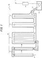
- the structure of a continuous hot-dip galvanizing apparatus 100 used in a method of producing a hot-dip galvanized steel sheet according to one of the disclosed embodiments is described first, with reference to FIG. 1 .
- the continuous hot-dip galvanizing apparatus 100 includes: an annealing furnace 20 in which a heating zone 10, a soaking zone 12, and cooling zones 14 and 16 are arranged in this order; a hot-dip galvanizing bath 22 as a hot-dip galvanizing line adjacent to the cooling zone 16; and an alloying line 23 adjacent to the hot-dip galvanizing bath 22.
- the heating zone 10 includes a first heating zone 10A (upstream heating zone) and a second heating zone 10B (downstream heating zone).
- the cooling zone includes a first cooling zone 14 (rapid cooling zone) and a second cooling zone 16 (slow cooling zone).
- a snout 18 connected to the second cooling zone 16 has its tip immersed in the hot-dip galvanizing bath 22, thus connecting the annealing furnace 20 and the hot-dip galvanizing bath 22.
- a steel strip P is introduced from a steel strip introduction port in the lower part of the first heating zone 10A into the first heating zone 10A.
- One or more hearth rolls are arranged in the upper and lower parts in each of the zones 10, 12, 14, and 16.
- the steel strip P is conveyed vertically a plurality of times inside the corresponding predetermined zone in the annealing furnace 20, forming a plurality of passes. While FIG. 1 illustrates an example of having 10 passes in the soaking zone 12, 2 passes in the first cooling zone 14, and 2 passes in the second cooling zone 16, the numbers of passes are not limited to such, and may be set as appropriate depending on the processing condition.
- the steel strip P is not folded back but changed in direction at the right angle to move to the next zone.
- the steel strip P is thus annealed in the annealing furnace 20 by being conveyed through the heating zone 10, the soaking zone 12, and the cooling zones 14 and 16 in this order.
- Adjacent zones in the annealing furnace 20 communicate through a communication portion connecting the upper parts or lower parts of the respective zones.
- the first heating zone 10A and the second heating zone 10B communicate through a throat (restriction portion) connecting the upper parts of the respective zones.
- the second heating zone 10B and the soaking zone 12 communicate through a throat connecting the lower parts of the respective zones.
- the soaking zone 12 and the first cooling zone 14 communicate through a throat connecting the lower parts of the respective zones.
- the first cooling zone 14 and the second cooling zone 16 communicate through a throat connecting the lower parts of the respective zones.
- the height of each throat may be set as appropriate. To enhance the independence of the atmosphere in each zone, the height of each throat is preferably as low as possible.
- the gas in the annealing furnace 20 flows from downstream to upstream in the furnace, and is discharged from the steel strip introduction port in the lower part of the first heating zone 10A.
- the second heating zone 10B is a direct fired furnace (DFF).
- the DFF may be a well-known DFF.
- a plurality of burners are distributed on the inner wall of the direct fired furnace in the second heating zone 10B so as to face the steel strip P, although not illustrated in FIG. 1 .
- the plurality of burners are divided into a plurality of groups, and the combustion rate and the air ratio in each group are independently controllable.
- Combustion exhaust gas in the second heating zone 10B is supplied into the first heating zone 10A, and the steel strip P is preheated by the heat of the gas.
- the combustion rate is a value obtained by dividing the amount of fuel gas actually introduced into a burner by the amount of fuel gas of the burner under its maximum combustion load.
- the combustion rate at the time of combustion by the burner under its maximum combustion load is 100 %.
- the combustion rate is preferably adjusted to 30 % or more.
- the air ratio is a value obtained by dividing the amount of air actually introduced into a burner by the amount of air necessary for complete combustion of fuel gas.
- the heating burners in the second heating zone 10B are divided into four groups (#1 to #4), and the three groups (#1 to #3) upstream in the steel sheet traveling direction are made up of oxidizing burners, and the last group (#4) is made up of reducing burners.
- the air ratio of the oxidizing burners and the air ratio of the reducing burners are independently controllable.
- the air ratio of the oxidizing burners is preferably adjusted to 0.95 or more and 1.5 or less.
- the air ratio of the reducing burners is preferably adjusted to 0.5 or more and less than 0.95.
- the temperature in the second heating zone 10B is preferably adjusted to 800 °C to 1200 °C.
- the soaking zone 12 is capable of indirectly heating the steel strip P using a radiant tube (RT) (not illustrated) as heating means.
- the average temperature Tr (°C) in the soaking zone 12 is measured by a thermocouple inserted into the soaking zone.
- the average temperature Tr (°C) in the soaking zone 12 is preferably adjusted to 700 °C to 900 °C.
- Reducing gas or non-oxidizing gas is supplied into the soaking zone 12.
- the reducing gas H 2 -N 2 mixed gas is typically used.
- An example is gas (dew point: about -60 °C) having a composition containing 1 vol% to 20 vol% H 2 with the balance being N 2 and incidental impurities.
- An example of the non-oxidizing gas is gas (dew point: about -60 °C) having a composition containing N 2 and incidental impurities.
- the reducing gas or non-oxidizing gas supplied into the soaking zone 12 has two forms, namely, humidified gas and dry gas.
- dry gas is reducing gas or non-oxidizing gas having a dew point of about -60 °C to -50 °C and not humidified by a humidifying device.
- humidity gas is gas humidified by a humidifying device to a dew point of 0 °C to 30 °C.
- the humidified gas is supplied to the soaking zone 12 in addition to the dry gas, in order to increase the dew point in the soaking zone.
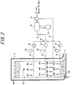
- FIG. 2 is a schematic diagram illustrating a system of supplying the humidified gas and the dry gas to the soaking zone 12.
- the humidified gas is supplied through three systems, namely, humidified gas supply ports 42A, 42B, and 42C, humidified gas supply ports 44A, 44B, and 44C, and humidified gas supply ports 46A, 46B, and 46C.
- a gas distribution device 24 feeds part of the reducing gas or non-oxidizing gas (dry gas) to a humidifying device 26.
- the remaining part passes through a dry gas pipe 32 as dry gas, and is supplied into the soaking zone 12 from dry gas supply ports 48A, 48B, 48C, and 48D.
- the positions and number of dry gas supply ports are not limited, and may be determined as appropriate based on various conditions.
- a plurality of dry gas supply ports are provided at the same height position.
- the dry gas supply ports are preferably distributed evenly in the steel strip traveling direction.
- the gas humidified in the humidifying device 26 is distributed into the three systems by a humidified gas distribution device 30, passes through respective humidified gas pipes 36, and is supplied into the soaking zone 12 from the humidified gas supply ports 42A, 42B, and 42C, the humidified gas supply ports 44A, 44B, and 44C, and the humidified gas supply ports 46A, 46B, and 46C.
- a humidified gas supply port is provided at each of one or more locations in each of four sections obtained by dividing the soaking zone 12 into halves in the vertical direction and dividing the soaking zone 12 into halves in the entry-delivery direction. This enables uniform dew point control for the whole soaking zone 12.
- Reference sign 38 is a humidified gas flowmeter
- reference sign 40 is a humidified gas dew point meter. Since the dew point of the humidified gas can change due to slight dew condensation in the humidified gas pipes 34 and 36 or the like, the dew point meters 40 are desirably located immediately before the humidified gas supply ports 42, 44, and 46.
- the humidifying device 26 includes a humidifying module having a fluorine or polyimide hollow fiber membrane, flat membrane, or the like. Dry gas flows inside the membrane, whereas pure water adjusted to a predetermined temperature in a circulating constant-temperature water bath 28 circulates outside the membrane.
- the fluorine or polyimide hollow fiber membrane or flat membrane is a type of ion exchange membrane with affinity for water molecules.
- the dry gas is humidified to the same dew point as the set water temperature, thus achieving highly accurate dew point control.
- the dew point of the humidified gas can be controlled to any value in the range of 5 °C to 50 °C.
- the pressure in the annealing furnace varies frequently depending on the combustion condition in the heating zone 10 and the cooling fan operating condition in the cooling zones 14 and 16. If the furnace pressure is excessively high, an excessive force acts on the furnace wall, which can damage the annealing furnace. If the furnace pressure is excessively low, oxygen outside the annealing furnace enters into the soaking zone 12 or the combustion gas in the heating zone 10 flows into the soaking zone 12, thus adversely affecting the steel sheet quality. Hence, such control that changes the flow rate of the gas supplied into the soaking zone 12 is typically performed so as to suppress the variation of the furnace pressure and preferably keep the furnace pressure constant.
- the conventional control method changes not only the flow rate of the dry gas but also the flow rate of the humidified gas. Consequently, the amount of moisture supplied into the soaking zone by the humidified gas varies.
- the soaking zone 12 needs to be constantly supplied with a necessary amount of moisture in terms of inducing internal oxidation of Si or Mn in the steel strip. If the flow rate of the humidified gas is decreased in order to suppress the variation of the furnace pressure, the amount of moisture supplied into the soaking zone 12 tends to become insufficient. This causes the dew point in the soaking zone 12 to fall below the lower limit of the appropriate range. As a result, partial non-coating occurs and degrades the coating appearance. Besides, in the operation that also involves alloying treatment, the alloying temperature tends to increase, making it impossible to obtain the desired tensile strength.
- the variation range of the amount of moisture supplied into the soaking zone is defined as (M max - M min )/M max , where M max is a maximum amount of moisture under the same operation condition and M min is a minimum amount of moisture under the same operation condition.
- the amount of moisture can be calculated according to the below-mentioned Formula (2).
- the dew point of the humidified gas is kept constant to control the variation range of its flow rate to 20 % or less.
- the amount of moisture M (g/min) introduced into the soaking zone 12 by the humidified gas needs to be adjusted depending on the volume of the soaking zone and the width and sheet passing speed of the steel strip P passing through the soaking zone 12.
- Setting the flow rate and dew point of the humidified gas so that the amount of moisture M (g/min) supplied into the soaking zone 12 by the humidified gas satisfies the following Formula (1) is effective in obtaining favorable coating appearance: 40 + Vf W ⁇ 0.9 S + 4 / 90 ⁇ M ⁇ 60 + Vf W ⁇ 0.9 S + 4 / 90
- Vf is the volume (m 3 ) of the soaking zone 12
- W is the width (m) of the steel strip P passing through the soaking zone 12
- S is the sheet passing speed (m/s) of the steel strip P.
- the volume Vf of the soaking zone 12 is substantially a constant.
- the width W and sheet passing speed S of the steel strip P passing through the soaking zone 12 increase or in the case where one of the width W and the sheet passing speed S is constant and the other one of the width W and the sheet passing speed S increases, the area of the steel strip in contact with the gas in the soaking zone 12 per unit time increases. Accordingly, the amount of moisture by the humidified gas is increased based on Formula (1).
- the amount of moisture by the humidified gas needs to be decreased based on Formula (1).
- the amount of moisture by the humidified gas is adjusted based on Formula (1). In any case, it is needed to adjust the flow rate and dew point of the humidified gas so as to satisfy Formula (1), before the dew point in the soaking zone 12 changes as a result of a change in the operation condition.
- the flow rate Vm of the humidified gas supplied into the soaking zone 12 is not limited as long as the aforementioned control is performed, but is generally maintained in the range of 100 to 400 (Nm 3 /hr).
- the flow rate of the dry gas supplied into the soaking zone 12 is not limited, but is generally maintained in the range of 10 to 300 (Nm 3 /hr).
- a dew point measurement port 50 is located in a region of upper 1/2 of the soaking zone 12 in the height direction.
- the vicinity of each humidified gas supply port is a region where the dew point is locally high, and therefore is not suitable for dew point measurement. Accordingly, the dew point measurement port 50 is located 1 m or more away from the position of each humidified gas supply port and 1 m or more away from the inner wall position of the soaking zone facing each of the supply ports.
- the cooling zones 14 and 16 cool the steel strip P.
- the steel strip P is cooled to about 480 °C to 530 °C in the first cooling zone 14, and cooled to about 470 °C to 500 °C in the second cooling zone 16.
- the cooling zones 14 and 16 are also supplied with the aforementioned reducing gas or non-oxidizing gas.
- the supply of the dry gas to the cooling zones 14 and 16 is not limited, but the dry gas is preferably supplied from introduction ports in two or more locations in the height direction and two or more locations in the longitudinal direction so that the dry gas is evenly introduced into the cooling zones.
- the total gas flow rate Qcd of the dry gas supplied into the cooling zones 14 and 16 is measured by a gas flowmeter (not illustrated) provided in the pipe.
- the total gas flow rate Qcd is not limited, but is set to about 200 to 1000 (Nm 3 /hr).
- the variation of the pressure in the annealing furnace may be suppressed by adjusting only the flow rate of the dry gas supplied into the soaking zone, but is preferably suppressed by also adjusting the flow rate of the dry gas supplied into the cooling zones.
- the hot-dip galvanizing bath 22 can be used to apply a hot-dip galvanized coating onto the steel strip P discharged from the second cooling zone 16.
- the hot-dip galvanizing may be performed according to a usual method.
- the alloying line 23 can be used to heat-alloy the galvanized coating applied on the steel strip P.
- the alloying treatment may be performed according to a usual method.
- the alloying temperature is kept from being high, thus preventing a decrease in tensile strength of the produced galvannealed steel sheet.
- the alloying line 23 and the alloying treatment by the alloying line 23 are not essential in the present disclosure. The effect of obtaining favorable coating appearance can be achieved even in the case of not performing alloying treatment.
- the steel strip P subjected to annealing and hot-dip galvanizing is not limited, but the advantageous effects according to the present disclosure can be effectively achieved in the case where the steel strip has a chemical composition containing 0.2 mass% or more Si, i.e. in the case of high tensile strength steel.
- the continuous hot-dip galvanizing apparatus illustrated in FIGS. 1 and 2 was used to anneal each steel strip whose chemical composition is listed in Table 1 under each annealing condition listed in Table 2, and then hot-dip galvanize and alloy the steel strip.
- Steel sample ID A and steel sample ID B are both high tensile strength steels.
- time denotes the time elapsed from the operation start, where the type, sheet thickness, and sheet width of the passing steel strip and the operation condition of the continuous hot-dip galvanizing apparatus were changed with the passage of time as listed in Table 2.
- a DFF was used as the second heating zone.
- the heating burners were divided into four groups (#1 to #4) where the three groups (#1 to #3) upstream in the steel sheet traveling direction were made up of oxidizing burners and the last group (#4) was made up of reducing burners, and the air ratios of the oxidizing burners and reducing burners were set to the values listed in Table 2.
- the length of each group in the steel sheet traveling direction was 4 m.
- a RT furnace having a volume Vr of 700 m 3 was used as the soaking zone.
- the average temperature Tr in the soaking zone was set to the value listed in Table 2.
- gas dew point: -50 °C
- Part of the dry gas was humidified by a humidifying device having 10 hollow fiber membrane-type humidifying modules, to prepare humidified gas. Dry gas of 500 L/min at the maximum and circulating water of 20 L/min at the maximum were flown in each module.
- a common circulating constant-temperature water bath capable of supplying pure water of 200 L/min in total was used for each module.
- the dry gas supply ports and the humidified gas supply ports were arranged at the positions illustrated in FIG. 2 .
- the dew point of the humidified gas was kept constant and the variation range of the flow rate of the humidified gas was limited to 20 % or less, as listed in Table 2.
- the furnace pressure was kept constant by adjusting the flow rate of the dry gas supplied into the soaking zone and the cooling zone.
- the field “dew point” of the soaking zone indicates the dew point in the soaking zone measured at the position of the dew point measurement port 50 in FIG. 2 .
- the field “dew point of vicinity of humidified gas supply port” indicates the dew point in the soaking zone measured at a position of 80 cm away from the humidified gas supply port 40B in FIG. 2 .
- the field “dew point of humidified gas” indicates the dew point measured by the humidified gas dew point meter 40 in FIG. 2 .
- the dry gas (dew point: -50 °C) was supplied into the first and second cooling zones from their lowermost parts with the flow rate listed in Table 2.
- the temperature of the molten bath was set to 460 °C
- the Al concentration in the molten bath was set to 0.130 %
- the coating weight was adjusted to 50 g/m 2 per surface by gas wiping.
- the line speed was set to 1.0 m/s to 2.0 m/s, with the change of the sheet thickness.
- alloying treatment was performed in an induction heating-type alloying furnace so that the coating alloying degree (Fe content) was 10 % to 13 %.
- the alloying temperature in the treatment is listed in Table 2.
Claims (3)
- Verfahren zur Herstellung eines feuerverzinkten Stahlblechs unter Verwendung einer Einrichtung zur kontinuierlichen Feuerverzinkung, umfassend: einen Glühofen, in dem eine Erwärmungszone, eine Einweichzone und eine Kühlzone in der angegebenen Reihenfolge angeordnet sind; und eine der Kühlzone benachbarte Feuerverzinkungslinie, wobei das Verfahren Folgendes umfasst:Glühen eines Stahlbandes, dessen Si-Gehalt 0,2 Masse-% oder mehr beträgt, durch Befördern des Stahlbandes durch die Erwärmungszone, die Einweichzone und die Kühlzone in der angegebenen Reihenfolge innerhalb des Glühofens; undAufbringen einer feuerverzinkten Beschichtung auf das aus der Kühlzone ausgetragene Stahlband unter Verwendung der Feuerverzinkungslinie,wobei Reduktionsgas oder nicht oxidierendes Gas in die Einweichzone zugeführt wird, wobei das Reduktionsgas oder das nicht oxidierende Gas Folgendes aufweist: befeuchtetes Gas, das von einer Befeuchtungsvorrichtung befeuchtet wird; und trockenes Gas, das von der Befeuchtungsvorrichtung nicht befeuchtet wird, undwährend eine Breite und eine Blechdurchlaufgeschwindigkeit des die Einweichzone durchlaufenden Stahlbandes konstant sind, eine Variation von Druck in dem Glühofen durch Einstellen einer Strömungsrate des trockenen Gases unterdrückt wird und ein Variationsbereich einer Feuchtigkeitsmenge, die durch das angefeuchtete Gas in die Einweichzone zugeführt wird, auf 20 % oder weniger begrenzt ist,wobei eine Strömungsrate und ein Taupunkt des angefeuchteten Gases so eingestellt sind, dass eine Feuchtigkeitsmenge M, die durch das angefeuchtete Gas in die Einweichzone zugeführt wird und in g/min ausgedrückt wird, die folgende Formel (1) erfüllt:
 wobei Vf ein Volumen der Einweichzone ist, ausgedrückt in m3, W die Breite des Stahlbandes ist, das die Einweichzone durchläuft, ausgedrückt in m, und S die Blechdurchlaufgeschwindigkeit des Stahlbandes, ausgedrückt in m/s, ist undwobei ein Taupunkt in der Einweichzone, gemessen an einem in der Einweichzone bereitgestellten Taupunktmessanschluss, auf -25 °C oder mehr und 0°C oder weniger geregelt wird, wobei der Taupunktmessanschluss in einem Bereich einer oberen 1/2 der Einweichzone in einer Höhenrichtung bereitgestellt ist und 1 m oder mehr weg von einer Position eines Zufuhranschlusses des in der Einweichzone bereitgestellten befeuchteten Gases und 1 m oder mehr weg von einer Innenwandposition der Einweichzone, die dem Zufuhranschluss zugewandt ist, angeordnet ist.
 - Verfahren zur Herstellung eines feuerverzinkten Stahlblechs nach Anspruch 1,
wobei, wenn mindestens einer der Breite und der Blechdurchlaufgeschwindigkeit des die Einweichzone durchlaufenden Stahlbandes variiert, die Strömungsgeschwindigkeit und der Taupunkt des befeuchteten Gases so geändert werden, dass die in g/min ausgedrückte Feuchtigkeitsmenge M die Formel (1) erfüllt. - Verfahren zur Herstellung eines feuerverzinkten Stahlblechs nach einem der Ansprüche 1 bis 2,
wobei die Erwärmungszone einen direkt befeuerten Ofen aufweist,
die Vorrichtung zur kontinuierlichen Feuerverzinkung eine Legierungslinie benachbart zu der Feuerverzinkungslinie aufweist, und
das Verfahren weiterhin Folgendes umfasst
Wärmelegieren der auf das Stahlband aufgebrachten verzinkten Beschichtung unter Verwendung der Legierungslinie.
Applications Claiming Priority (2)
| Application Number | Priority Date | Filing Date | Title |
|---|---|---|---|
| JP2015211121A JP6439654B2 (ja) | 2015-10-27 | 2015-10-27 | 溶融亜鉛めっき鋼板の製造方法 |
| PCT/JP2016/003631 WO2017072989A1 (ja) | 2015-10-27 | 2016-08-05 | 溶融亜鉛めっき鋼板の製造方法 |
Publications (3)
| Publication Number | Publication Date |
|---|---|
| EP3369836A1 EP3369836A1 (de) | 2018-09-05 |
| EP3369836A4 EP3369836A4 (de) | 2018-11-07 |
| EP3369836B1 true EP3369836B1 (de) | 2019-10-09 |
Family
ID=58630053
Family Applications (1)
| Application Number | Title | Priority Date | Filing Date |
|---|---|---|---|
| EP16859230.1A Active EP3369836B1 (de) | 2015-10-27 | 2016-08-05 | Verfahren zur herstellung eines feuerverzinkten stahlblechs |
Country Status (7)
| Country | Link |
|---|---|
| US (1) | US20180237896A1 (de) |
| EP (1) | EP3369836B1 (de) |
| JP (1) | JP6439654B2 (de) |
| KR (1) | KR102072560B1 (de) |
| CN (1) | CN108138297B (de) |
| MX (1) | MX2018005073A (de) |
| WO (1) | WO2017072989A1 (de) |
Families Citing this family (3)
| Publication number | Priority date | Publication date | Assignee | Title |
|---|---|---|---|---|
| JP6455544B2 (ja) * | 2017-05-11 | 2019-01-23 | Jfeスチール株式会社 | 溶融亜鉛めっき鋼板の製造方法 |
| US11384419B2 (en) * | 2019-08-30 | 2022-07-12 | Micromaierials Llc | Apparatus and methods for depositing molten metal onto a foil substrate |
| JP7364092B2 (ja) * | 2021-07-14 | 2023-10-18 | Jfeスチール株式会社 | 溶融亜鉛めっき鋼板の製造方法 |
Family Cites Families (11)
| Publication number | Priority date | Publication date | Assignee | Title |
|---|---|---|---|---|
| JPS61217531A (ja) * | 1985-03-22 | 1986-09-27 | Kawasaki Steel Corp | 鋼帯の冷却方法 |
| JPH089737B2 (ja) * | 1989-05-24 | 1996-01-31 | 日本鋼管株式会社 | 直火式▲堅▼型連続焼鈍炉およびその操業方法 |
| JP4791482B2 (ja) * | 2005-10-14 | 2011-10-12 | 新日本製鐵株式会社 | Siを含有する鋼板の連続焼鈍溶融めっき方法及び連続焼鈍溶融めっき装置 |
| JP5338087B2 (ja) * | 2008-03-03 | 2013-11-13 | Jfeスチール株式会社 | めっき性に優れる溶融亜鉛めっき鋼板の製造方法および連続溶融亜鉛めっき設備 |
| JP5720084B2 (ja) | 2009-03-06 | 2015-05-20 | Jfeスチール株式会社 | 連続溶融亜鉛めっき装置および溶融亜鉛めっき鋼板の製造方法 |
| CN102453792B (zh) * | 2010-10-26 | 2013-07-17 | 宝山钢铁股份有限公司 | 连续退火炉炉压控制方法及控制设备 |
| DE102011051731B4 (de) * | 2011-07-11 | 2013-01-24 | Thyssenkrupp Steel Europe Ag | Verfahren zur Herstellung eines durch Schmelztauchbeschichten mit einer metallischen Schutzschicht versehenen Stahlflachprodukts |
| JP5505461B2 (ja) * | 2012-05-24 | 2014-05-28 | Jfeスチール株式会社 | 鋼帯の連続焼鈍炉、鋼帯の連続焼鈍方法、連続溶融亜鉛めっき設備及び溶融亜鉛めっき鋼帯の製造方法 |
| CN106029932B (zh) * | 2014-02-25 | 2019-03-15 | 杰富意钢铁株式会社 | 还原炉的露点控制方法以及还原炉 |
| JP6020605B2 (ja) * | 2015-01-08 | 2016-11-02 | Jfeスチール株式会社 | 合金化溶融亜鉛めっき鋼板の製造方法 |
| JP6008007B2 (ja) * | 2015-03-23 | 2016-10-19 | Jfeスチール株式会社 | 連続溶融亜鉛めっき装置及び溶融亜鉛めっき鋼板の製造方法 |
-
2015
- 2015-10-27 JP JP2015211121A patent/JP6439654B2/ja active Active
-
2016
- 2016-08-05 KR KR1020187013015A patent/KR102072560B1/ko active IP Right Grant
- 2016-08-05 EP EP16859230.1A patent/EP3369836B1/de active Active
- 2016-08-05 US US15/753,260 patent/US20180237896A1/en not_active Abandoned
- 2016-08-05 WO PCT/JP2016/003631 patent/WO2017072989A1/ja active Application Filing
- 2016-08-05 MX MX2018005073A patent/MX2018005073A/es unknown
- 2016-08-05 CN CN201680060387.7A patent/CN108138297B/zh active Active
Non-Patent Citations (1)
| Title |
|---|
| None * |
Also Published As
| Publication number | Publication date |
|---|---|
| JP2017082278A (ja) | 2017-05-18 |
| WO2017072989A1 (ja) | 2017-05-04 |
| KR20180064497A (ko) | 2018-06-14 |
| CN108138297B (zh) | 2020-06-23 |
| JP6439654B2 (ja) | 2018-12-19 |
| EP3369836A4 (de) | 2018-11-07 |
| EP3369836A1 (de) | 2018-09-05 |
| US20180237896A1 (en) | 2018-08-23 |
| KR102072560B1 (ko) | 2020-02-03 |
| CN108138297A (zh) | 2018-06-08 |
| MX2018005073A (es) | 2018-05-28 |
Similar Documents
| Publication | Publication Date | Title |
|---|---|---|
| EP3243924B1 (de) | Verfahren zur herstellung eines galvanisierten stahlblechs | |
| EP3623492B1 (de) | Verfahren zur herstellung eines feuerverzinkten stahlblechs | |
| EP3168321B1 (de) | Herstellungsverfahren für legiertes feuerverzinktes stahlblech | |
| EP3112493B1 (de) | Verfahren zur steuerung des taupunktes eines reduktionsofens und reduktionsofen | |
| EP3276037B1 (de) | Verfahren zur herstellung von feuerverzinktem stahlblech | |
| US11649520B2 (en) | Continuous hot dip galvanizing apparatus | |
| US20230323501A1 (en) | Continuous hot-dip galvanizing apparatus | |
| EP3369836B1 (de) | Verfahren zur herstellung eines feuerverzinkten stahlblechs | |
| JP6128068B2 (ja) | 合金化溶融亜鉛めっき鋼板の製造方法 | |
| JP7334860B2 (ja) | 連続焼鈍炉の露点制御方法、鋼板の連続焼鈍方法、鋼板の製造方法、連続焼鈍炉、連続溶融亜鉛めっき設備及び合金化溶融亜鉛めっき設備 | |
| WO2023286501A1 (ja) | 溶融亜鉛めっき鋼板の製造方法 |
Legal Events
| Date | Code | Title | Description |
|---|---|---|---|
| STAA | Information on the status of an ep patent application or granted ep patent |
Free format text: STATUS: THE INTERNATIONAL PUBLICATION HAS BEEN MADE |
|
| PUAI | Public reference made under article 153(3) epc to a published international application that has entered the european phase |
Free format text: ORIGINAL CODE: 0009012 |
|
| STAA | Information on the status of an ep patent application or granted ep patent |
Free format text: STATUS: REQUEST FOR EXAMINATION WAS MADE |
|
| 17P | Request for examination filed |
Effective date: 20180315 |
|
| AK | Designated contracting states |
Kind code of ref document: A1 Designated state(s): AL AT BE BG CH CY CZ DE DK EE ES FI FR GB GR HR HU IE IS IT LI LT LU LV MC MK MT NL NO PL PT RO RS SE SI SK SM TR |
|
| AX | Request for extension of the european patent |
Extension state: BA ME |
|
| REG | Reference to a national code |
Ref country code: DE Ref legal event code: R079 Ref document number: 602016022348 Country of ref document: DE Free format text: PREVIOUS MAIN CLASS: C23C0002020000 Ipc: C21D0001760000 |
|
| A4 | Supplementary search report drawn up and despatched |
Effective date: 20181008 |
|
| RIC1 | Information provided on ipc code assigned before grant |
Ipc: C21D 9/56 20060101ALI20181001BHEP Ipc: C23C 2/40 20060101ALI20181001BHEP Ipc: C23C 2/06 20060101ALI20181001BHEP Ipc: C23C 2/02 20060101ALI20181001BHEP Ipc: C23C 2/28 20060101ALI20181001BHEP Ipc: C21D 1/76 20060101AFI20181001BHEP |
|
| DAV | Request for validation of the european patent (deleted) | ||
| DAX | Request for extension of the european patent (deleted) | ||
| GRAP | Despatch of communication of intention to grant a patent |
Free format text: ORIGINAL CODE: EPIDOSNIGR1 |
|
| STAA | Information on the status of an ep patent application or granted ep patent |
Free format text: STATUS: GRANT OF PATENT IS INTENDED |
|
| INTG | Intention to grant announced |
Effective date: 20190604 |
|
| GRAS | Grant fee paid |
Free format text: ORIGINAL CODE: EPIDOSNIGR3 |
|
| GRAA | (expected) grant |
Free format text: ORIGINAL CODE: 0009210 |
|
| STAA | Information on the status of an ep patent application or granted ep patent |
Free format text: STATUS: THE PATENT HAS BEEN GRANTED |
|
| AK | Designated contracting states |
Kind code of ref document: B1 Designated state(s): AL AT BE BG CH CY CZ DE DK EE ES FI FR GB GR HR HU IE IS IT LI LT LU LV MC MK MT NL NO PL PT RO RS SE SI SK SM TR |
|
| REG | Reference to a national code |
Ref country code: GB Ref legal event code: FG4D |
|
| REG | Reference to a national code |
Ref country code: CH Ref legal event code: EP |
|
| REG | Reference to a national code |
Ref country code: IE Ref legal event code: FG4D |
|
| REG | Reference to a national code |
Ref country code: DE Ref legal event code: R096 Ref document number: 602016022348 Country of ref document: DE |
|
| REG | Reference to a national code |
Ref country code: AT Ref legal event code: REF Ref document number: 1188882 Country of ref document: AT Kind code of ref document: T Effective date: 20191115 |
|
| REG | Reference to a national code |
Ref country code: NL Ref legal event code: MP Effective date: 20191009 |
|
| REG | Reference to a national code |
Ref country code: LT Ref legal event code: MG4D |
|
| REG | Reference to a national code |
Ref country code: AT Ref legal event code: MK05 Ref document number: 1188882 Country of ref document: AT Kind code of ref document: T Effective date: 20191009 |
|
| PG25 | Lapsed in a contracting state [announced via postgrant information from national office to epo] |
Ref country code: AT Free format text: LAPSE BECAUSE OF FAILURE TO SUBMIT A TRANSLATION OF THE DESCRIPTION OR TO PAY THE FEE WITHIN THE PRESCRIBED TIME-LIMIT Effective date: 20191009 Ref country code: NL Free format text: LAPSE BECAUSE OF FAILURE TO SUBMIT A TRANSLATION OF THE DESCRIPTION OR TO PAY THE FEE WITHIN THE PRESCRIBED TIME-LIMIT Effective date: 20191009 Ref country code: PL Free format text: LAPSE BECAUSE OF FAILURE TO SUBMIT A TRANSLATION OF THE DESCRIPTION OR TO PAY THE FEE WITHIN THE PRESCRIBED TIME-LIMIT Effective date: 20191009 Ref country code: ES Free format text: LAPSE BECAUSE OF FAILURE TO SUBMIT A TRANSLATION OF THE DESCRIPTION OR TO PAY THE FEE WITHIN THE PRESCRIBED TIME-LIMIT Effective date: 20191009 Ref country code: LT Free format text: LAPSE BECAUSE OF FAILURE TO SUBMIT A TRANSLATION OF THE DESCRIPTION OR TO PAY THE FEE WITHIN THE PRESCRIBED TIME-LIMIT Effective date: 20191009 Ref country code: BG Free format text: LAPSE BECAUSE OF FAILURE TO SUBMIT A TRANSLATION OF THE DESCRIPTION OR TO PAY THE FEE WITHIN THE PRESCRIBED TIME-LIMIT Effective date: 20200109 Ref country code: FI Free format text: LAPSE BECAUSE OF FAILURE TO SUBMIT A TRANSLATION OF THE DESCRIPTION OR TO PAY THE FEE WITHIN THE PRESCRIBED TIME-LIMIT Effective date: 20191009 Ref country code: SE Free format text: LAPSE BECAUSE OF FAILURE TO SUBMIT A TRANSLATION OF THE DESCRIPTION OR TO PAY THE FEE WITHIN THE PRESCRIBED TIME-LIMIT Effective date: 20191009 Ref country code: NO Free format text: LAPSE BECAUSE OF FAILURE TO SUBMIT A TRANSLATION OF THE DESCRIPTION OR TO PAY THE FEE WITHIN THE PRESCRIBED TIME-LIMIT Effective date: 20200109 Ref country code: LV Free format text: LAPSE BECAUSE OF FAILURE TO SUBMIT A TRANSLATION OF THE DESCRIPTION OR TO PAY THE FEE WITHIN THE PRESCRIBED TIME-LIMIT Effective date: 20191009 Ref country code: GR Free format text: LAPSE BECAUSE OF FAILURE TO SUBMIT A TRANSLATION OF THE DESCRIPTION OR TO PAY THE FEE WITHIN THE PRESCRIBED TIME-LIMIT Effective date: 20200110 Ref country code: PT Free format text: LAPSE BECAUSE OF FAILURE TO SUBMIT A TRANSLATION OF THE DESCRIPTION OR TO PAY THE FEE WITHIN THE PRESCRIBED TIME-LIMIT Effective date: 20200210 |
|
| PG25 | Lapsed in a contracting state [announced via postgrant information from national office to epo] |
Ref country code: RS Free format text: LAPSE BECAUSE OF FAILURE TO SUBMIT A TRANSLATION OF THE DESCRIPTION OR TO PAY THE FEE WITHIN THE PRESCRIBED TIME-LIMIT Effective date: 20191009 Ref country code: HR Free format text: LAPSE BECAUSE OF FAILURE TO SUBMIT A TRANSLATION OF THE DESCRIPTION OR TO PAY THE FEE WITHIN THE PRESCRIBED TIME-LIMIT Effective date: 20191009 Ref country code: IS Free format text: LAPSE BECAUSE OF FAILURE TO SUBMIT A TRANSLATION OF THE DESCRIPTION OR TO PAY THE FEE WITHIN THE PRESCRIBED TIME-LIMIT Effective date: 20200224 |
|
| PG25 | Lapsed in a contracting state [announced via postgrant information from national office to epo] |
Ref country code: AL Free format text: LAPSE BECAUSE OF FAILURE TO SUBMIT A TRANSLATION OF THE DESCRIPTION OR TO PAY THE FEE WITHIN THE PRESCRIBED TIME-LIMIT Effective date: 20191009 |
|
| REG | Reference to a national code |
Ref country code: DE Ref legal event code: R097 Ref document number: 602016022348 Country of ref document: DE |
|
| PG2D | Information on lapse in contracting state deleted |
Ref country code: IS |
|
| PG25 | Lapsed in a contracting state [announced via postgrant information from national office to epo] |
Ref country code: CZ Free format text: LAPSE BECAUSE OF FAILURE TO SUBMIT A TRANSLATION OF THE DESCRIPTION OR TO PAY THE FEE WITHIN THE PRESCRIBED TIME-LIMIT Effective date: 20191009 Ref country code: RO Free format text: LAPSE BECAUSE OF FAILURE TO SUBMIT A TRANSLATION OF THE DESCRIPTION OR TO PAY THE FEE WITHIN THE PRESCRIBED TIME-LIMIT Effective date: 20191009 Ref country code: DK Free format text: LAPSE BECAUSE OF FAILURE TO SUBMIT A TRANSLATION OF THE DESCRIPTION OR TO PAY THE FEE WITHIN THE PRESCRIBED TIME-LIMIT Effective date: 20191009 Ref country code: EE Free format text: LAPSE BECAUSE OF FAILURE TO SUBMIT A TRANSLATION OF THE DESCRIPTION OR TO PAY THE FEE WITHIN THE PRESCRIBED TIME-LIMIT Effective date: 20191009 Ref country code: IS Free format text: LAPSE BECAUSE OF FAILURE TO SUBMIT A TRANSLATION OF THE DESCRIPTION OR TO PAY THE FEE WITHIN THE PRESCRIBED TIME-LIMIT Effective date: 20200209 |
|
| PLBE | No opposition filed within time limit |
Free format text: ORIGINAL CODE: 0009261 |
|
| STAA | Information on the status of an ep patent application or granted ep patent |
Free format text: STATUS: NO OPPOSITION FILED WITHIN TIME LIMIT |
|
| PG25 | Lapsed in a contracting state [announced via postgrant information from national office to epo] |
Ref country code: SK Free format text: LAPSE BECAUSE OF FAILURE TO SUBMIT A TRANSLATION OF THE DESCRIPTION OR TO PAY THE FEE WITHIN THE PRESCRIBED TIME-LIMIT Effective date: 20191009 Ref country code: IT Free format text: LAPSE BECAUSE OF FAILURE TO SUBMIT A TRANSLATION OF THE DESCRIPTION OR TO PAY THE FEE WITHIN THE PRESCRIBED TIME-LIMIT Effective date: 20191009 Ref country code: SM Free format text: LAPSE BECAUSE OF FAILURE TO SUBMIT A TRANSLATION OF THE DESCRIPTION OR TO PAY THE FEE WITHIN THE PRESCRIBED TIME-LIMIT Effective date: 20191009 |
|
| 26N | No opposition filed |
Effective date: 20200710 |
|
| PG25 | Lapsed in a contracting state [announced via postgrant information from national office to epo] |
Ref country code: SI Free format text: LAPSE BECAUSE OF FAILURE TO SUBMIT A TRANSLATION OF THE DESCRIPTION OR TO PAY THE FEE WITHIN THE PRESCRIBED TIME-LIMIT Effective date: 20191009 |
|
| PG25 | Lapsed in a contracting state [announced via postgrant information from national office to epo] |
Ref country code: MC Free format text: LAPSE BECAUSE OF FAILURE TO SUBMIT A TRANSLATION OF THE DESCRIPTION OR TO PAY THE FEE WITHIN THE PRESCRIBED TIME-LIMIT Effective date: 20191009 |
|
| REG | Reference to a national code |
Ref country code: CH Ref legal event code: PL |
|
| PG25 | Lapsed in a contracting state [announced via postgrant information from national office to epo] |
Ref country code: CH Free format text: LAPSE BECAUSE OF NON-PAYMENT OF DUE FEES Effective date: 20200831 Ref country code: LI Free format text: LAPSE BECAUSE OF NON-PAYMENT OF DUE FEES Effective date: 20200831 Ref country code: LU Free format text: LAPSE BECAUSE OF NON-PAYMENT OF DUE FEES Effective date: 20200805 |
|
| REG | Reference to a national code |
Ref country code: BE Ref legal event code: MM Effective date: 20200831 |
|
| PG25 | Lapsed in a contracting state [announced via postgrant information from national office to epo] |
Ref country code: BE Free format text: LAPSE BECAUSE OF NON-PAYMENT OF DUE FEES Effective date: 20200831 Ref country code: IE Free format text: LAPSE BECAUSE OF NON-PAYMENT OF DUE FEES Effective date: 20200805 |
|
| PG25 | Lapsed in a contracting state [announced via postgrant information from national office to epo] |
Ref country code: TR Free format text: LAPSE BECAUSE OF FAILURE TO SUBMIT A TRANSLATION OF THE DESCRIPTION OR TO PAY THE FEE WITHIN THE PRESCRIBED TIME-LIMIT Effective date: 20191009 Ref country code: MT Free format text: LAPSE BECAUSE OF FAILURE TO SUBMIT A TRANSLATION OF THE DESCRIPTION OR TO PAY THE FEE WITHIN THE PRESCRIBED TIME-LIMIT Effective date: 20191009 Ref country code: CY Free format text: LAPSE BECAUSE OF FAILURE TO SUBMIT A TRANSLATION OF THE DESCRIPTION OR TO PAY THE FEE WITHIN THE PRESCRIBED TIME-LIMIT Effective date: 20191009 |
|
| PG25 | Lapsed in a contracting state [announced via postgrant information from national office to epo] |
Ref country code: MK Free format text: LAPSE BECAUSE OF FAILURE TO SUBMIT A TRANSLATION OF THE DESCRIPTION OR TO PAY THE FEE WITHIN THE PRESCRIBED TIME-LIMIT Effective date: 20191009 |
|
| PGFP | Annual fee paid to national office [announced via postgrant information from national office to epo] |
Ref country code: GB Payment date: 20220630 Year of fee payment: 7 |
|
| PGFP | Annual fee paid to national office [announced via postgrant information from national office to epo] |
Ref country code: FR Payment date: 20230703 Year of fee payment: 8 Ref country code: DE Payment date: 20230627 Year of fee payment: 8 |
|
| GBPC | Gb: european patent ceased through non-payment of renewal fee |
Effective date: 20230805 |