EP3367397A2 - Betriebsmitteltraganordnung - Google Patents
Betriebsmitteltraganordnung Download PDFInfo
- Publication number
- EP3367397A2 EP3367397A2 EP18157829.5A EP18157829A EP3367397A2 EP 3367397 A2 EP3367397 A2 EP 3367397A2 EP 18157829 A EP18157829 A EP 18157829A EP 3367397 A2 EP3367397 A2 EP 3367397A2
- Authority
- EP
- European Patent Office
- Prior art keywords
- load
- holding means
- transformer
- equipment support
- support arrangement
- Prior art date
- Legal status (The legal status is an assumption and is not a legal conclusion. Google has not performed a legal analysis and makes no representation as to the accuracy of the status listed.)
- Granted
Links
Images


Classifications
-
- H—ELECTRICITY
- H01—ELECTRIC ELEMENTS
- H01F—MAGNETS; INDUCTANCES; TRANSFORMERS; SELECTION OF MATERIALS FOR THEIR MAGNETIC PROPERTIES
- H01F27/00—Details of transformers or inductances, in general
- H01F27/002—Arrangements provided on the transformer facilitating its transport
-
- H—ELECTRICITY
- H01—ELECTRIC ELEMENTS
- H01F—MAGNETS; INDUCTANCES; TRANSFORMERS; SELECTION OF MATERIALS FOR THEIR MAGNETIC PROPERTIES
- H01F27/00—Details of transformers or inductances, in general
- H01F27/06—Mounting, supporting or suspending transformers, reactors or choke coils not being of the signal type
-
- B—PERFORMING OPERATIONS; TRANSPORTING
- B60—VEHICLES IN GENERAL
- B60P—VEHICLES ADAPTED FOR LOAD TRANSPORTATION OR TO TRANSPORT, TO CARRY, OR TO COMPRISE SPECIAL LOADS OR OBJECTS
- B60P1/00—Vehicles predominantly for transporting loads and modified to facilitate loading, consolidating the load, or unloading
- B60P1/02—Vehicles predominantly for transporting loads and modified to facilitate loading, consolidating the load, or unloading with parallel up-and-down movement of load supporting or containing element
-
- F—MECHANICAL ENGINEERING; LIGHTING; HEATING; WEAPONS; BLASTING
- F16—ENGINEERING ELEMENTS AND UNITS; GENERAL MEASURES FOR PRODUCING AND MAINTAINING EFFECTIVE FUNCTIONING OF MACHINES OR INSTALLATIONS; THERMAL INSULATION IN GENERAL
- F16F—SPRINGS; SHOCK-ABSORBERS; MEANS FOR DAMPING VIBRATION
- F16F15/00—Suppression of vibrations in systems; Means or arrangements for avoiding or reducing out-of-balance forces, e.g. due to motion
- F16F15/02—Suppression of vibrations of non-rotating, e.g. reciprocating systems; Suppression of vibrations of rotating systems by use of members not moving with the rotating systems
-
- F—MECHANICAL ENGINEERING; LIGHTING; HEATING; WEAPONS; BLASTING
- F16—ENGINEERING ELEMENTS AND UNITS; GENERAL MEASURES FOR PRODUCING AND MAINTAINING EFFECTIVE FUNCTIONING OF MACHINES OR INSTALLATIONS; THERMAL INSULATION IN GENERAL
- F16M—FRAMES, CASINGS OR BEDS OF ENGINES, MACHINES OR APPARATUS, NOT SPECIFIC TO ENGINES, MACHINES OR APPARATUS PROVIDED FOR ELSEWHERE; STANDS; SUPPORTS
- F16M5/00—Engine beds, i.e. means for supporting engines or machines on foundations
Definitions
- the invention relates to a Beriebskartragan Aunt for electrical equipment, in particular for transformers or power transformers, high voltage power transformers, reactors, power transformers with phase shift and a mobile and "resiliency transformer".
- the actual replacement of such a defective transformer is associated with a relatively large technical effort, and includes in steps the removal of the old transformer and / or its removal and the shipment or delivery of the new Transformers with the aid of a suitable means of transport, such as a suitably equipped low loader, to the respective site. Then the transformer is to be unloaded from the respective means of transport and to be arranged and set up at the respective place of use on a specially equipped and fixed foundation.
- a suitable means of transport such as a suitably equipped low loader
- the object of the invention is to facilitate a simplified simplified replacement of an electrical equipment, in particular a power transformer, which avoids the aforementioned disadvantages.
- the device support arrangement comprises holding means arranged on the operating means, as well as a support arrangement with a plurality of load receivers, in particular four column-like support feet, wherein the respective electrical equipment, in particular a transformer or power transformer, in the end position with the holding means on the Load pickups is discontinued and / or after weaning at least partially rests and arranged between the load receivers.
- the setup and unloading process is thereby advantageously simplified by the fact that, when using a semi-low loader trailer with a platform or loading surface with hydraulic lifting function or with hydraulic height adjustment, the use of a mobile heavy-duty crane can be dispensed with by the respective operating means, in particular the Transformer is transported by means of the trailer to the installation site, the loading area is initially raised so far that the holding means are freely movable on the load carriers and can be positioned over this and after alignment of the holding means on the load receivers, in particular after centric alignment, the loading area is lowered so that the holding means and thus the equipment rest in the final position on the load receivers. The loading area is then lowered further until the trailer and / or the loading area under the transformer is freely movable or movable and can be moved away from it.
- the load carriers are arranged on a foundation carrying the load of the electrical equipment, in particular a concrete foundation.
- At least one damping element or vibration damper and / or an anti-vibration pad is provided between the load receiver and the foundation and / or between the load receiver and the holding means.
- the Radionauttraganordung at least four holding means arranged on the holding means, which in particular uniformly distributed or symmetrically attached to the respective equipment by means of welding, riveting, by means of bolts and / or screwing and / or latching, in particular releasably secured detachably.
- the holding means is furthermore advantageously possible to provide for the holding means to be arranged on the operating means in a height-adjustable and / or vertically adjustable manner, for example along a guide or guide rail.
- the guide has holes for the passage of bolts and or screws for fastening the respective holding means.
- the load receivers are designed to be adjustable in height in several parts from at least two mutually rotatable interlocking threaded load-bearing components.
- an anti-rotation is further providable, which prevents unwanted rotation of both components and unintentional adjustment of the height and locks both components against each other and fixed.
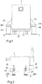
- FIG. 1 an exemplarily designed Radioffentragan Aunt for a transformer 2 is shown, which four at the resources, here the transformer, self-arranged holding means 3a, b, c, d, and a support assembly with four load receivers 4a, b, c, d, so-called.
- Load stabilizers ", in particular four columnar support legs or settling boxes, also referred to as elephant feet includes.
- the load receivers 4a, b, c, d shown here by way of example as dropping boxes are made of steel and have a cylindrical shape with a diameter of about 1 m and a height of about 1.3 m.
- Each of the settling boxes shown here is designed for a load of up to approx. 35t. However, the dimensioning ultimately depends on the load to be carried by the respective equipment, in the case of the transformer shown here. Accordingly, sales cans can be formed with a larger load.
- the respective electrical equipment in particular the transformer in the end position with the holding means 3a, b, c, d deposited on the load pickups 4a, b, c, d and / or resting after weaning at least partially between the load receivers 4a, b, c, d and / or is arranged between them.
- the loading area 21 is or is first raised so far, so that the holding means 3a, b, c, d are freely movable over the load receivers 4a, b, c, d and can be positioned over the latter and after alignment of the holding means 3a, b, c, d over the load transducers 4a, b, c, d, in particular after centric alignment, see also Fig. 3 , the loading area 21 is lowered such that the holding means and thus the transformer 2 rest in the end position on the load receivers 4a, b, c, d. The loading area 21 is then lowered further until the trailer 20 and / or the loading area 21 under the transformer 2 is freely movable or movable and can be moved away from it.
- the load receptor 4a, b, c, d are arranged on a load bearing the transformer 2 foundation, in particular a concrete foundation.
- the resource carrying arrangement includes, as in Fig. 3 indicated, at least four arranged on the operating means holding means 3a, b, c, d which are in particular evenly distributed or symmetrically secured to the respective operating means by means of bolts and / or screwed.
- the holding means 3a, b, c, d are, as in Fig. 2 removable, the transformer 2 height adjustable and / or vertically adjustable along a guide 30 or guide rail arranged.
- the guide can have holes arranged in the vertical longitudinal direction for the passage of bolts and / or screws for fastening the respective holding means.
- the settling cans with the holding means 3a, b, c, d which in the here shown FIGS. 4 and 5 are designed as lifting plates 5a, b, screwed to order ensure that they do not slip during operation due to the vibrations of the transformer or change their position.
- the aforementioned screw is not explicitly shown in the figures.
- the holding means 3a, b, c, d designed as lifting plates 7a, b here comprise two parallel vertical steel plates 5a, b, which are provided with a horizontally oriented in FIG. 3 shown steel plate 5c is connected, in particular screwed, which in turn rests in the end position on the load transducers 4a, b, c, d or Absetzdosen.
- the respective holding means 3a, b, c, d or lifting plates in turn can be screwed to the transformer 2 to a perforated strip 6, wherein the perforated strip 6 ensures a flexible height adjustment of the system.
Landscapes
- Engineering & Computer Science (AREA)
- Power Engineering (AREA)
- General Engineering & Computer Science (AREA)
- Mechanical Engineering (AREA)
- Physics & Mathematics (AREA)
- Acoustics & Sound (AREA)
- Aviation & Aerospace Engineering (AREA)
- Transportation (AREA)
- Housings And Mounting Of Transformers (AREA)
Abstract
Description
- Die Erfindung betrifft eine Beriebsmitteltraganordnung für elektrische Betriebsmittel, insbesondere für Transformatoren oder Leistungstransformatoren, Hochspannungs-Leistungstransformatoren, Reaktoren, Leistungstransformatoren mit Phasenverschiebung sowie einen mobilen und "resiliency transformer".
- Mobile Transformatoren werden heute aufgrund ihr vielfältigen Einsatzmöglichkeiten vermehrt eingesetzt. Sie sind mobil, nicht an den jeweiligen Einsatzort gebunden, so dass mit ihrer Hilfe sehr schnell ein nicht voll einsatzfähiger beziehungsweise beschädigter Transformator ersetzt werden kann.
Ein nicht voll einsatzfähiger Transformator mit ggf. reduzierten Leistungswerten stellt dabei ein ernstzunehmendes Problem dar, da dessen Reparatur durchaus mehrere Wochen bis Monate ja bis zu einem Jahr in Anspruch nehmen kann, wobei während der Wartezeit das Risiko eines Totalausfalls immer weiter ansteigt. Ein Ausfall des Transformators könnte dabei zu erheblichen Folgeschäden, letztlich auch im Hinblick auf das jeweilige Versorgungsnetz, beispielsweise zu Produktionsausfällen und die eingesetzten Geräte führen. - Die Möglichkeit eines schnellen Austauschs eines solchen Transformators, ist dabei von grundlegender Bedeutung auch für die Zuverlässigkeit und Ausfallsicherheit eines Strom- und/oder Versorgungsnetzes.
- Der eigentliche Austausch eines solchen defekten Transformators ist dabei jedoch mit einem vergleichsweise großen technischen Aufwand verbunden, und umfasst in Schritten die Entfernung des alten Transformators und/oder dessen Abtransport sowie die Verbringung beziehungsweise Anlieferung des neuen Transformators unter Zuhilfenahme eines geeigneten Transportmittels, wie beispielsweise einen entsprechend eingerichteten Tieflader, an den jeweiligen Einsatzort.
Anschließend ist der Transformator vom jeweiligen Transportmittel abzuladen und am jeweiligen Einsatzort auf einem speziell dafür eingerichteten und befestigten Fundament anzuordnen und aufzustellen. Um dies zu ermöglichen ist aufgrund des hohen Eigengewichtes des jeweiligen Transformators der Einsatz wenigstens eines mobilen Schwerlastkrans erforderlich. Ein solcher Kran ist vergleichsweise groß und dafür eingerichtet die Last des jeweiligen Transformators zu heben und/oder zu bewegen. Weiterhin sind diese terminlich oft nur in einem sehr schmalen Zeitfenster verfügbar. Aufgrund ihrer Größe und ihres Gewichtes können auch sie in aller Regel nur bestimmte Strecken und Straßen befahren, was dazu führen kann, dass sie nicht immer pünktlich am Einsatzort verfügbar sind, was den Transformatoraustausch zusätzlich erschweren und verzögern kann. - Die Aufgabe der Erfindung besteht darin, einen erleichterten vereinfachten Austausch eines elektrischen Betriebsmittels, insbesondere eines Leistungstransformators, welcher die vorgenannten Nachteile vermeidet, zu ermöglichen.
- Diese Aufgabe wird durch eine Betriebsmitteltraganordnung für elektrische Betriebsmittel, insbesondere für einen elektrischen Leistungstransformator, gemäß den Merkmalen des Anspruchs 1 gelöst.
- Vorteilhafte Ausgestaltungen und Weiterbildungen der Erfindung sind in weiteren Ansprüchen und der nachfolgenden Beschreibung angegeben.
- Die erfindungsgemäße Betriebsmitteltraganordnung umfasst dabei am Betriebsmittel selbst angeordnete Haltemittel, sowie eine Stützanordnung mit mehreren Lastaufnehmern, sog. "load stabilizers", insbesondere vier säulenartig ausgebildete Stützfüße, wobei das jeweilige elektrische Betriebsmittel, insbesondere ein Transformator oder Leistungstransformator, in Endposition mit den Haltemitteln auf den Lastaufnehmern abgesetzt ist und/oder nach dem Absetzen zumindest teilbereichsweise zwischen den Lastaufnehmern ruht und angeordnet ist.
- Vorteilhaft ist dabei der Aufstell- und Abladevorgang dadurch vereinfachbar, dass bei Verwendung eines semi-low loader trailers mit einer Plattform oder Ladefläche mit hydraulischer Hebefunktion beziehungsweise mit hydraulischer Höhenverstellung auf den Einsatz eines mobilen Schwerlastkrans verzichtet werden kann, indem der das jeweilige Betriebsmittel, insbesondere der Transformator, mittels des Trailers zum Aufstellort verbracht wird, die Ladefläche, zunächst soweit angehoben wird dass die Haltemittel über den Lastaufnehmern frei beweglich sind und über diesen positionierbar sind und nach Ausrichtung der Haltemittel über den Lastaufnehmern, insbesondere nach zentrischer Ausrichtung die Ladefläche derart abgesenkt wird, dass die Haltemittel und damit das Betriebsmittel in Endlage auf den Lastaufnehmern ruhen. Die Ladefläche wird dann weiter abgesenkt bis der Trailer und/oder die Ladefläche unter dem Transformator freigängig bewegbar beziehungsweise verfahrbar und von diesem wegbewegbar ist.
- Vorteilhaft sind die Lastaufnehmer dabei auf einem die Last des elektrischen Betriebsmittels tragenden Fundament, insbesondere einem Betonfundament, angeordnet.
- In einer weiteren Ausgestaltung ist jeweils zwischen Lastaufnehmer und Fundament und/oder zwischen Lastaufnehmer und Haltemittel wenigstens ein Dämpfungselement beziehungsweise Schwingungsdämpfer und/oder eine anti-vibrations Unterlage, vorgesehen.
- In einer weiteren Ausgestaltung umfasst die Betriebsmitteltraganordung wenigstens vier am Betriebsmittel angeordnete Haltemittel, welche insbesondere gleichverteilt oder symmetrisch an dem jeweiligen Betriebsmittel mittels Verschweißung, Vernietung, mittels Bolzen und/oder Verschraubung und/oder Verrastung befestigt, insbesondere beschädigungsfrei lösbar befestigt sind.
- Vorteilhaft ist dabei weiterhin vorsehbar, dass die Haltemittel am Betriebsmittel höhenverstellbar und/oder vertikal verstellbar, beispielsweise entlang einer Führung oder Führungsschiene, angeordnet sind.
- Auch ist vorsehbar, dass die Führung Bohrungen zum Durchgriff von Bolzen und oder Schrauben zur Befestigung des jeweiligen Haltemittels aufweist.
- Weiterbildend kann weiterhin vorgesehen sein, dass die Lastaufnehmer mehrteilig aus wenigstens zwei gegeneinander verdrehbaren, ineinandergreifenden mit Gewinde versehenen Lastaufnehmerkomponenten höhenverstellbar ausgebildet sind.
Vorteilhaft ist weiterhin eine Verdrehsicherung vorsehbar, die eine ungewollte Verdrehung beider Komponenten und ungewollte Verstellung der Höhe verhindert und beide Komponenten gegeneinander arretiert und fixiert. - Weiterhin beansprucht wird ein entsprechendes Aufstellverfahren für ein elektrisches Betriebsmittel mittels der vorbeschriebenen Betriebsmitteltraganordnung sowie die Verwendung von Lastaufnehmern für das Aufstellen eines elektrischen Betriebsmittels, insbesondere eines Transformators oder Leistungstransformators.
- Die weitere Darlegung der Erfindung sowie vorteilhafter Ausgestaltungen und Weiterbildungen erfolgt anhand einiger Figuren und Ausführungsbeispiele.
- Es zeigen:
-
Fig. 1 Beispielhaft ausgebildete Betriebsmitteltraganordnung mit Transformator und Tieflader -
Fig. 2 Beispielhaft ausgebildete Betriebsmitteltraganordnung mit abgesetztem Transformator -
Fig. 3 Beispielhaft ausgebildete Betriebsmitteltraganordnung mit abgesetztem Transformator in Seitenansicht -
Fig. 4 Beispielhaft ausgebildete Betriebsmitteltraganordnung mit abgesetztem Transformator in Draufsicht -
Fig. 5 Beispielhaft ausgebildete Betriebsmitteltraganordnung mit Haltemitteln und Lastaufnehmern - In
Fig . 1 ist eine beispielhaft ausgebildete Betriebsmitteltraganordnung für einen Transformator 2 gezeigt, welche vier am Betriebsmittel, hier dem Transformator, selbst angeordnete Haltemittel 3a,b,c,d, sowie eine Stützanordnung mit vier Lastaufnehmern 4a,b,c,d, sog. "load stabilizers", insbesondere vier säulenartig ausgebildete Stützfüße oder Absetzdosen, auch als Elefantenfüße bezeichnet, umfasst. Die hier beispielhaft gezeigten als Absetzdosen ausgebildeten Lastaufnehmer 4a,b,c,d sind aus Stahl gebildet und haben eine zylindrische Form mit einem Durchmesser von ca. 1 m und einer Höhe von ca. 1,3 m.
Jede der hier beispielhaft gezeigten Absetzdosen ist für eine Belastung von bis zu ca. 35t ausgelegt. Die Dimensionierung hängt dabei jedoch letztlich von der zu tragenden Last des jeweiligen Betriebsmittels, im hier gezeigten Fall des Transformators ab. Demgemäß sind auch Absatzdosen mit einer größeren Traglast ausbildbar. - Unter die jeweiligen Lastaufnehmer beziehungsweise Absetzdosen ist eine vergleichsweise große, wenige Zentimeter dicke Stahlplatte 5 legbar, um die Lasten des aufzunehmenden Betriebsmittels besser auf dem Boden zu verteilen.
- In Endlage beziehungsweise Endposition ist das jeweilige elektrische Betriebsmittel, insbesondere der Transformator in Endposition mit den Haltemitteln 3a,b,c,d auf den Lastaufnehmern 4a,b,c,d abgesetzt und/oder ruht nach dem Absetzen zumindest teilbereichsweise zwischen den Lastaufnehmern 4a,b,c,d und/oder ist zwischen ihnen angeordnet.
- Der Aufstell- und Abladevorgang dabei dadurch vereinfacht, dass bei Verwendung eines semi-low loader trailers 20, wie in
Fig. 1 und3 gezeigt, mit einer Plattform oder Ladefläche 21 mit hydraulischer Hebefunktion beziehungsweise mit hydraulischer Höhenverstellung auf den Einsatz eines mobilen Schwerlastkrans verzichtet werden kann, indem der Transformator 2, der mit seiner Bodenfläche beziehungsweise Unterseite auf der Ladefläche des Trailers 20 abgestellt ist und mittels des Trailers 20 zum Aufstellort verbracht wird. Die Ladefläche 21 ist beziehungsweise wird zunächst soweit angehoben, so dass die Haltemittel 3a,b,c,d über den Lastaufnehmern 4a,b,c,d frei beweglich sind und über diesen positionierbar sind und nach Ausrichtung der Haltemittel 3a,b,c,d über den Lastaufnehmern 4a,b,c,d, insbesondere nach zentrischer Ausrichtung, siehe auchFig. 3 , die Ladefläche 21 derart abgesenkt wird, dass die Haltemittel und damit der Transformator 2 in Endlage auf den Lastaufnehmern 4a,b,c,d ruhen. Die Ladefläche 21 wird dann weiter abgesenkt bis der Trailer 20 und/oder die Ladefläche 21 unter dem Transformator 2 freigängig bewegbar beziehungsweise verfahrbar und von diesem wegbewegbar ist. - Die Lastaufnehmer 4a,b,c,d sind dabei auf einem die Last des Transformators 2 tragenden Fundament, insbesondere einem Betonfundament, angeordnet.
- Auch ist, wie in
Figur 1 gezeigt, jeweils zwischen Lastaufnehmer 4a,b,c,d und Fundament 26 und/oder zwischen Lastaufnehmer 4a,b,c,d und Haltemittel 3a,b,c,d jeweils wenigstens ein Dämpfungselement beziehungsweise Schwingungsdämpfer und/oder anti-vibrations Unterlage 28a,b, vorgesehen. - Die Betriebsmitteltraganordung umfasst, wie in
Fig. 3 angegeben, wenigstens vier am Betriebsmittel angeordnete Haltemittel 3a,b,c,d welche insbesondere gleichverteilt oder symmetrisch an dem jeweiligen Betriebsmittel mittels Bolzen und/oder Verschraubung lösbar befestigt sind.
Die Haltemittel 3a,b,c,d sind, wie inFig. 2 entnehmbar, am Transformator 2 höhenverstellbar und/oder vertikal verstellbar entlang einer Führung 30 oder Führungsschiene, angeordnet. - Die Führung kann dabei in vertikaler Längsrichtung angeordnete Bohrungen zum Durchgriff von Bolzen und oder Schrauben zur Befestigung des jeweiligen Haltemittels aufweisen.
- Die Absetzdosen werden mit den Haltemitteln 3a,b,c,d , welche im hier gezeigten der
Figuren 4 und5 als Anhebeplatten 5a,b ausgebildet sind, verschraubt, um sicherzustellen, dass diese nicht im Betrieb durch die Vibrationen des Trafos verrutschen oder ihre Position verändern. Vorgenannte Verschraubung ist in den Figuren nicht explizit gezeigt.
Die als Anhebeplatten 7a,b ausgebildeten Haltemittel 3a,b,c,d umfassen dabei zwei parallele senkrechte Stahlplatten 5a,b, die mit einer waagerecht ausgerichteten inFigur 3 gezeigten Stahlplatte 5c verbunden ist, insbesondere verschraubt ist, die in Endlage wiederum auf den Lastaufnehmern 4a,b,c,d beziehungsweise Absetzdosen aufliegt. - Die jeweiligen Haltemittel 3a,b,c,d beziehungsweise Anhebeplatten wiederum können mit dem Transformator 2 an eine Lochleiste 6 verschraubt werden, wobei die Lochleiste 6 eine flexible Höheneinstellung des Systems gewährleistet.
Claims (7)
- Betriebsmitteltraganordnung für ein elektrisches Betriebsmittel, insbesondere einen transformator oder Leistungstransformator, umfassend mehrere am Betriebsmittel selbst angeordnete Haltemittel (3a,b,c,d), sowie eine Stützanordnung mit mehreren Lastaufnehmern (4a,b,c,d), , insbesondere vier säulenartig ausgebildete Stützfüße, wobei das jeweilige elektrische Betriebsmittel (2) in Endlage mit den Haltemitteln (3a,b,c,d) auf den Lastaufnehmern (4a,b,c,d) abgesetzt ist und/oder nach dem Absetzen zumindest teilbereichsweise zwischen den Lastaufnehmern (4a,b,c,d) ruht und angeordnet ist.
- Betriebsmitteltraganordnung nach Anspruch 1, dadurch gekennzeichnet, dass die Lastaufnehmer (4a,b,c,d) dabei auf einem die Last des elektrischen Betriebsmittels tragenden Fundament, insbesondere einem Betonfundament, angeordnet sind.
- Betriebsmitteltraganordnung nach einem der Ansprüche 1 oder 2, dadurch gekennzeichnet, dass zwischen Lastaufnehmer (4a,b,c,d) und Fundament und/oder zwischen Lastaufnehmer (4a,b,c,d) und Haltemittel (3a,b,c,d) wenigstens ein Dämpfungselement beziehungsweise Schwingungsdämpfer und/oder eine anti-vibrations Unterlage, angeordnet ist.
- Betriebsmitteltraganordnung nach einem der vorherigen Ansprüche, dadurch gekennzeichnet, dass wenigstens vier am Betriebsmittel (2) angeordnete Haltemittel (3a,b,c,d), welche insbesondere gleichverteilt oder symmetrisch an dem jeweiligen Betriebsmittel beschädigungsfrei lösbar befestigt und höhenverstellbar und/oder vertikal versetzbar sind.
- Betriebsmitteltraganordnung nach einem der vorherigen Ansprüche, dadurch gekennzeichnet, dass die Haltemitteln (3a,b,c,d) als Anhebeplatten (5a,b) ausgebildet sind, und jeweils zwei parallele senkrechte Stahlplatten aufweisen, die mit einer waagerecht ausgerichteten Stahlplatte (5c) verbunden sind.
- Verfahren zur Aufstellung eines elektrischen Betriebmittels (2) mittels der Betriebsmitteltraganordnung nach einem der Ansprüche 1, wobei unter Verwendung eines semi-low loader trailers oder Tiefladers (20) mit einer Plattform oder Ladefläche mit hydraulischer Hebefunktion beziehungsweise mit hydraulischer Höhenverstellung auf den Einsatz eines mobilen Schwerlastkrans verzichtet werden kann, indem das jeweilige Betriebsmittel (2), insbesondere der Transformator, mittels des Trailers (20) zum Aufstellort verbracht wird, die Ladefläche, zunächst soweit angehoben wird dass die Haltemittel (3a,b,c,d) über den Lastaufnehmern (4a,b,c,d) der Betriebsmitteltraganordnung frei beweglich sind und über diesen positionierbar sind und nach Ausrichtung der Haltemittel (3a,b,c,d) über den Lastaufnehmern (4a,b,c,d), die Ladefläche derart abgesenkt wird, dass die Haltemittel (3a,b,c,d) und damit das Betriebsmittel (2) in Endlage auf den Lastaufnehmern (4a,b,c,d) ruhen, wobei die Ladefläche dann weiter abgesenkt wird bis der Trailer (20) und/oder die Ladefläche unter dem Betriebsmittel (2) freigängig bewegbar beziehungsweise verfahrbar und unter diesem wegbewegbar ist.
- Verwendung von Lastaufnehmern (4a,b,c,d), insbesondere Absetzdosen, für das Aufstellen eines Transformators oder Leistungstransformators, insbesondere nach dem Verfahren nach Anspruch 6.
Applications Claiming Priority (1)
| Application Number | Priority Date | Filing Date | Title |
|---|---|---|---|
| DE102017103927.9A DE102017103927A1 (de) | 2017-02-24 | 2017-02-24 | Betriebsmitteltraganordnung |
Publications (3)
| Publication Number | Publication Date |
|---|---|
| EP3367397A2 true EP3367397A2 (de) | 2018-08-29 |
| EP3367397A3 EP3367397A3 (de) | 2018-09-19 |
| EP3367397B1 EP3367397B1 (de) | 2023-09-27 |
Family
ID=61258158
Family Applications (1)
| Application Number | Title | Priority Date | Filing Date |
|---|---|---|---|
| EP18157829.5A Active EP3367397B1 (de) | 2017-02-24 | 2018-02-21 | Betriebsmitteltraganordnung |
Country Status (3)
| Country | Link |
|---|---|
| US (1) | US11081272B2 (de) |
| EP (1) | EP3367397B1 (de) |
| DE (1) | DE102017103927A1 (de) |
Cited By (2)
| Publication number | Priority date | Publication date | Assignee | Title |
|---|---|---|---|---|
| CN111540571A (zh) * | 2019-10-16 | 2020-08-14 | 浙江季布电力工程有限公司 | 一种电力工程变压器用的安装装置 |
| CN113035510A (zh) * | 2021-05-26 | 2021-06-25 | 广东力王高新科技股份有限公司 | 一种装配维修方便的卤素灯预热电子变压器 |
Family Cites Families (19)
| Publication number | Priority date | Publication date | Assignee | Title |
|---|---|---|---|---|
| US3377601A (en) * | 1966-10-27 | 1968-04-09 | Westinghouse Electric Corp | Mobile electrical transformer apparatus having means for moving the transformer between operating and transit positions |
| US3841032A (en) * | 1972-05-17 | 1974-10-15 | Chance Co Ab | Article and screw anchor-supported, load-bearing pad therefor |
| US4505449A (en) * | 1980-02-22 | 1985-03-19 | Diversitech Corporation | Lightweight concrete cladded heavy equipment base |
| JPS5839016U (ja) * | 1981-09-07 | 1983-03-14 | 三菱電機株式会社 | 電気装置 |
| DE3841279A1 (de) * | 1988-12-08 | 1990-06-13 | Betonbau Gmbh | Transportabler transformatorenstand fuer freilufttransformatoren |
| JPH07192916A (ja) * | 1993-12-27 | 1995-07-28 | Toshiba Corp | 電気機器 |
| JP4366034B2 (ja) * | 2001-10-02 | 2009-11-18 | 株式会社日立製作所 | タービン発電設備 |
| DE102010012408A1 (de) | 2010-03-23 | 2011-09-29 | Powerwind Gmbh | Trägeranordnung für eine Windenergieanlage, Windenergieanlage mit einer Trägeranordnung und Verfahren zum Errichten einer Windenergieanlage |
| US9421898B2 (en) * | 2012-06-29 | 2016-08-23 | Guillaume Huet | Trailer for lifting a heavy load and method for lifting the heavy load using the same |
| DE202013002851U1 (de) * | 2013-03-23 | 2013-05-16 | Alstom Technology Ltd. | Aufnahmevorrichtung zur Aufnahme einer Hochspannungsvorrichtung |
| US20160138263A1 (en) * | 2013-07-09 | 2016-05-19 | Asahi Kasei Homes Corporation | Damping device |
| US9555731B2 (en) * | 2014-02-28 | 2017-01-31 | GM Global Technology Operations LLC | Truck body with rapid load/unload cargo pods |
| EP2955729A1 (de) | 2014-06-13 | 2015-12-16 | Siemens Aktiengesellschaft | Stützvorrichtung eines Aktivteils eines Stromwandlers |
| JP6231457B2 (ja) * | 2014-10-23 | 2017-11-15 | ファナック株式会社 | 除振装置及びロボットを搭載した位置決め装置 |
| US10071671B2 (en) * | 2015-03-20 | 2018-09-11 | BeOutsourced LLC | System and method for delivery and installation of automobile tires |
| WO2016193913A1 (en) * | 2015-06-03 | 2016-12-08 | Brl Patents Limited | Securing assembly |
| DE102016209893A1 (de) * | 2016-06-06 | 2017-12-07 | Jungheinrich Aktiengesellschaft | Flurförderzeug mit einer Einrichtung zur Reduzierung von Schwingungen |
| US20180044835A1 (en) * | 2016-08-09 | 2018-02-15 | Seicon Limited | Vibration-Isolator Platform |
| US10059249B2 (en) * | 2016-08-22 | 2018-08-28 | General Electric Company | Compact and reusable shipping attachments for securing heavy machinery on a deck |
-
2017
- 2017-02-24 DE DE102017103927.9A patent/DE102017103927A1/de not_active Ceased
-
2018
- 2018-02-21 EP EP18157829.5A patent/EP3367397B1/de active Active
- 2018-02-23 US US15/903,067 patent/US11081272B2/en active Active
Non-Patent Citations (1)
| Title |
|---|
| None |
Cited By (2)
| Publication number | Priority date | Publication date | Assignee | Title |
|---|---|---|---|---|
| CN111540571A (zh) * | 2019-10-16 | 2020-08-14 | 浙江季布电力工程有限公司 | 一种电力工程变压器用的安装装置 |
| CN113035510A (zh) * | 2021-05-26 | 2021-06-25 | 广东力王高新科技股份有限公司 | 一种装配维修方便的卤素灯预热电子变压器 |
Also Published As
| Publication number | Publication date |
|---|---|
| US11081272B2 (en) | 2021-08-03 |
| US20180247752A1 (en) | 2018-08-30 |
| EP3367397A3 (de) | 2018-09-19 |
| DE102017103927A1 (de) | 2018-08-30 |
| EP3367397B1 (de) | 2023-09-27 |
Similar Documents
| Publication | Publication Date | Title |
|---|---|---|
| DE102008014544A1 (de) | Vorrichtung zur Reparatur einer Schadstelle in einem unter Wasser befindlichen Wandbereich eines Behälters oder Beckens | |
| EP3485097B1 (de) | Rüttleranordnung | |
| WO2012092953A1 (de) | Mobile brechanlage | |
| DE102013206596A1 (de) | Schwerlaststütze | |
| EP4334230B1 (de) | Topmodul und verfahren zum abschliessen eines aufzugschachts einer aufzuganlage | |
| EP3601137B1 (de) | Verfahren und montagevorrichtung zum durchführen eines installationsvorgangs in einem aufzugschacht einer aufzuganlage | |
| EP3367397B1 (de) | Betriebsmitteltraganordnung | |
| EP1875015A2 (de) | Steigleitung für die förderung von dickstoffen | |
| DE3420737A1 (de) | Zusatzeinrichtung fuer hoehenverstellbare arbeitsgerueste | |
| DE102009031272B3 (de) | Laschplattform mit Magazin für Twistlocks | |
| EP4339398A1 (de) | Übergangssegment eines windkraft-turmbauwerks | |
| DE102017110995A1 (de) | Vorpresse und System zum kontinuierlichen Herstellen von Werkstoffplatten, Verfahren zum Einbringen oder Entnehmen des Pressenbandes und Transportvorrichtung zum Aufnehmen des Pressenbandes | |
| DE102011050340A1 (de) | Randschalungselement | |
| DE102010005866B4 (de) | Anlage zur Herstellung von Betonfertigteilen | |
| AT525229B1 (de) | Waage zum Wägen eines Abrollcontainers | |
| DE102013223536A1 (de) | Verkippungssystem | |
| EP0690547B1 (de) | Einbau eines Stators in ein Gehäuse | |
| DE202010013019U1 (de) | Ablagegestell und Wagen zum senkrechten Anordnen von Gipsplattenelementen zur Verwendung an einem Arbeitsplatz | |
| DE102007029149A1 (de) | Ladebrücke mit neuartig gelagertem Hubzylinder | |
| EP4048945A1 (de) | Auflagervorrichtung, lastkörperanordnung sowie verfahren zum einstellen einer auf auflagervorrichtungen der lastkörperanordnung wirkenden auflagerkraft | |
| EP1795489B1 (de) | Hubsystem. | |
| DE3739645A1 (de) | Ortsveraenderliche anlage zur herstellung von beton | |
| EP4311802B1 (de) | Transportachse für den transport eines turmdrehkrans sowie verfahren zum transportieren eines turmdrehkrans mittels einer transportachse | |
| WO2025036738A1 (de) | Verfahren zur installation einer aufzuganlage | |
| EP4001046A1 (de) | Wartungseinrichtung für schienenfahrzeuge, fahrwerk eines schienenfahrzeugs und wartungsverfahren |
Legal Events
| Date | Code | Title | Description |
|---|---|---|---|
| PUAI | Public reference made under article 153(3) epc to a published international application that has entered the european phase |
Free format text: ORIGINAL CODE: 0009012 |
|
| STAA | Information on the status of an ep patent application or granted ep patent |
Free format text: STATUS: THE APPLICATION HAS BEEN PUBLISHED |
|
| PUAL | Search report despatched |
Free format text: ORIGINAL CODE: 0009013 |
|
| AK | Designated contracting states |
Kind code of ref document: A2 Designated state(s): AL AT BE BG CH CY CZ DE DK EE ES FI FR GB GR HR HU IE IS IT LI LT LU LV MC MK MT NL NO PL PT RO RS SE SI SK SM TR |
|
| AX | Request for extension of the european patent |
Extension state: BA ME |
|
| AK | Designated contracting states |
Kind code of ref document: A3 Designated state(s): AL AT BE BG CH CY CZ DE DK EE ES FI FR GB GR HR HU IE IS IT LI LT LU LV MC MK MT NL NO PL PT RO RS SE SI SK SM TR |
|
| AX | Request for extension of the european patent |
Extension state: BA ME |
|
| RIC1 | Information provided on ipc code assigned before grant |
Ipc: H01F 27/00 20060101AFI20180810BHEP |
|
| STAA | Information on the status of an ep patent application or granted ep patent |
Free format text: STATUS: REQUEST FOR EXAMINATION WAS MADE |
|
| 17P | Request for examination filed |
Effective date: 20190314 |
|
| RBV | Designated contracting states (corrected) |
Designated state(s): AL AT BE BG CH CY CZ DE DK EE ES FI FR GB GR HR HU IE IS IT LI LT LU LV MC MK MT NL NO PL PT RO RS SE SI SK SM TR |
|
| RAP1 | Party data changed (applicant data changed or rights of an application transferred) |
Owner name: ABB SCHWEIZ AG |
|
| RAP1 | Party data changed (applicant data changed or rights of an application transferred) |
Owner name: ABB POWER GRIDS SWITZERLAND AG |
|
| STAA | Information on the status of an ep patent application or granted ep patent |
Free format text: STATUS: EXAMINATION IS IN PROGRESS |
|
| 17Q | First examination report despatched |
Effective date: 20210527 |
|
| RAP3 | Party data changed (applicant data changed or rights of an application transferred) |
Owner name: HITACHI ENERGY SWITZERLAND AG |
|
| GRAP | Despatch of communication of intention to grant a patent |
Free format text: ORIGINAL CODE: EPIDOSNIGR1 |
|
| STAA | Information on the status of an ep patent application or granted ep patent |
Free format text: STATUS: GRANT OF PATENT IS INTENDED |
|
| INTG | Intention to grant announced |
Effective date: 20230418 |
|
| P01 | Opt-out of the competence of the unified patent court (upc) registered |
Effective date: 20230524 |
|
| GRAS | Grant fee paid |
Free format text: ORIGINAL CODE: EPIDOSNIGR3 |
|
| GRAA | (expected) grant |
Free format text: ORIGINAL CODE: 0009210 |
|
| STAA | Information on the status of an ep patent application or granted ep patent |
Free format text: STATUS: THE PATENT HAS BEEN GRANTED |
|
| AK | Designated contracting states |
Kind code of ref document: B1 Designated state(s): AL AT BE BG CH CY CZ DE DK EE ES FI FR GB GR HR HU IE IS IT LI LT LU LV MC MK MT NL NO PL PT RO RS SE SI SK SM TR |
|
| REG | Reference to a national code |
Ref country code: GB Ref legal event code: FG4D Free format text: NOT ENGLISH |
|
| REG | Reference to a national code |
Ref country code: CH Ref legal event code: EP |
|
| REG | Reference to a national code |
Ref country code: DE Ref legal event code: R096 Ref document number: 502018013302 Country of ref document: DE |
|
| REG | Reference to a national code |
Ref country code: IE Ref legal event code: FG4D Free format text: LANGUAGE OF EP DOCUMENT: GERMAN |
|
| RAP2 | Party data changed (patent owner data changed or rights of a patent transferred) |
Owner name: HITACHI ENERGY LTD |
|
| REG | Reference to a national code |
Ref country code: LT Ref legal event code: MG9D |
|
| PG25 | Lapsed in a contracting state [announced via postgrant information from national office to epo] |
Ref country code: GR Free format text: LAPSE BECAUSE OF FAILURE TO SUBMIT A TRANSLATION OF THE DESCRIPTION OR TO PAY THE FEE WITHIN THE PRESCRIBED TIME-LIMIT Effective date: 20231228 |
|
| PG25 | Lapsed in a contracting state [announced via postgrant information from national office to epo] |
Ref country code: SE Free format text: LAPSE BECAUSE OF FAILURE TO SUBMIT A TRANSLATION OF THE DESCRIPTION OR TO PAY THE FEE WITHIN THE PRESCRIBED TIME-LIMIT Effective date: 20230927 Ref country code: RS Free format text: LAPSE BECAUSE OF FAILURE TO SUBMIT A TRANSLATION OF THE DESCRIPTION OR TO PAY THE FEE WITHIN THE PRESCRIBED TIME-LIMIT Effective date: 20230927 Ref country code: NO Free format text: LAPSE BECAUSE OF FAILURE TO SUBMIT A TRANSLATION OF THE DESCRIPTION OR TO PAY THE FEE WITHIN THE PRESCRIBED TIME-LIMIT Effective date: 20231227 Ref country code: LV Free format text: LAPSE BECAUSE OF FAILURE TO SUBMIT A TRANSLATION OF THE DESCRIPTION OR TO PAY THE FEE WITHIN THE PRESCRIBED TIME-LIMIT Effective date: 20230927 Ref country code: LT Free format text: LAPSE BECAUSE OF FAILURE TO SUBMIT A TRANSLATION OF THE DESCRIPTION OR TO PAY THE FEE WITHIN THE PRESCRIBED TIME-LIMIT Effective date: 20230927 Ref country code: HR Free format text: LAPSE BECAUSE OF FAILURE TO SUBMIT A TRANSLATION OF THE DESCRIPTION OR TO PAY THE FEE WITHIN THE PRESCRIBED TIME-LIMIT Effective date: 20230927 Ref country code: GR Free format text: LAPSE BECAUSE OF FAILURE TO SUBMIT A TRANSLATION OF THE DESCRIPTION OR TO PAY THE FEE WITHIN THE PRESCRIBED TIME-LIMIT Effective date: 20231228 Ref country code: FI Free format text: LAPSE BECAUSE OF FAILURE TO SUBMIT A TRANSLATION OF THE DESCRIPTION OR TO PAY THE FEE WITHIN THE PRESCRIBED TIME-LIMIT Effective date: 20230927 |
|
| REG | Reference to a national code |
Ref country code: NL Ref legal event code: MP Effective date: 20230927 |
|
| PG25 | Lapsed in a contracting state [announced via postgrant information from national office to epo] |
Ref country code: NL Free format text: LAPSE BECAUSE OF FAILURE TO SUBMIT A TRANSLATION OF THE DESCRIPTION OR TO PAY THE FEE WITHIN THE PRESCRIBED TIME-LIMIT Effective date: 20230927 |
|
| PG25 | Lapsed in a contracting state [announced via postgrant information from national office to epo] |
Ref country code: IS Free format text: LAPSE BECAUSE OF FAILURE TO SUBMIT A TRANSLATION OF THE DESCRIPTION OR TO PAY THE FEE WITHIN THE PRESCRIBED TIME-LIMIT Effective date: 20240127 |
|
| PG25 | Lapsed in a contracting state [announced via postgrant information from national office to epo] |
Ref country code: ES Free format text: LAPSE BECAUSE OF FAILURE TO SUBMIT A TRANSLATION OF THE DESCRIPTION OR TO PAY THE FEE WITHIN THE PRESCRIBED TIME-LIMIT Effective date: 20230927 |
|
| PG25 | Lapsed in a contracting state [announced via postgrant information from national office to epo] |
Ref country code: SM Free format text: LAPSE BECAUSE OF FAILURE TO SUBMIT A TRANSLATION OF THE DESCRIPTION OR TO PAY THE FEE WITHIN THE PRESCRIBED TIME-LIMIT Effective date: 20230927 Ref country code: RO Free format text: LAPSE BECAUSE OF FAILURE TO SUBMIT A TRANSLATION OF THE DESCRIPTION OR TO PAY THE FEE WITHIN THE PRESCRIBED TIME-LIMIT Effective date: 20230927 Ref country code: IS Free format text: LAPSE BECAUSE OF FAILURE TO SUBMIT A TRANSLATION OF THE DESCRIPTION OR TO PAY THE FEE WITHIN THE PRESCRIBED TIME-LIMIT Effective date: 20240127 Ref country code: ES Free format text: LAPSE BECAUSE OF FAILURE TO SUBMIT A TRANSLATION OF THE DESCRIPTION OR TO PAY THE FEE WITHIN THE PRESCRIBED TIME-LIMIT Effective date: 20230927 Ref country code: EE Free format text: LAPSE BECAUSE OF FAILURE TO SUBMIT A TRANSLATION OF THE DESCRIPTION OR TO PAY THE FEE WITHIN THE PRESCRIBED TIME-LIMIT Effective date: 20230927 Ref country code: CZ Free format text: LAPSE BECAUSE OF FAILURE TO SUBMIT A TRANSLATION OF THE DESCRIPTION OR TO PAY THE FEE WITHIN THE PRESCRIBED TIME-LIMIT Effective date: 20230927 Ref country code: SK Free format text: LAPSE BECAUSE OF FAILURE TO SUBMIT A TRANSLATION OF THE DESCRIPTION OR TO PAY THE FEE WITHIN THE PRESCRIBED TIME-LIMIT Effective date: 20230927 Ref country code: PT Free format text: LAPSE BECAUSE OF FAILURE TO SUBMIT A TRANSLATION OF THE DESCRIPTION OR TO PAY THE FEE WITHIN THE PRESCRIBED TIME-LIMIT Effective date: 20240129 |
|
| PG25 | Lapsed in a contracting state [announced via postgrant information from national office to epo] |
Ref country code: PL Free format text: LAPSE BECAUSE OF FAILURE TO SUBMIT A TRANSLATION OF THE DESCRIPTION OR TO PAY THE FEE WITHIN THE PRESCRIBED TIME-LIMIT Effective date: 20230927 Ref country code: IT Free format text: LAPSE BECAUSE OF FAILURE TO SUBMIT A TRANSLATION OF THE DESCRIPTION OR TO PAY THE FEE WITHIN THE PRESCRIBED TIME-LIMIT Effective date: 20230927 |
|
| REG | Reference to a national code |
Ref country code: DE Ref legal event code: R097 Ref document number: 502018013302 Country of ref document: DE |
|
| PG25 | Lapsed in a contracting state [announced via postgrant information from national office to epo] |
Ref country code: DK Free format text: LAPSE BECAUSE OF FAILURE TO SUBMIT A TRANSLATION OF THE DESCRIPTION OR TO PAY THE FEE WITHIN THE PRESCRIBED TIME-LIMIT Effective date: 20230927 |
|
| PG25 | Lapsed in a contracting state [announced via postgrant information from national office to epo] |
Ref country code: DK Free format text: LAPSE BECAUSE OF FAILURE TO SUBMIT A TRANSLATION OF THE DESCRIPTION OR TO PAY THE FEE WITHIN THE PRESCRIBED TIME-LIMIT Effective date: 20230927 |
|
| PLBE | No opposition filed within time limit |
Free format text: ORIGINAL CODE: 0009261 |
|
| STAA | Information on the status of an ep patent application or granted ep patent |
Free format text: STATUS: NO OPPOSITION FILED WITHIN TIME LIMIT |
|
| REG | Reference to a national code |
Ref country code: GB Ref legal event code: 732E Free format text: REGISTERED BETWEEN 20240718 AND 20240724 |
|
| REG | Reference to a national code |
Ref country code: DE Ref legal event code: R119 Ref document number: 502018013302 Country of ref document: DE |
|
| 26N | No opposition filed |
Effective date: 20240628 |
|
| PG25 | Lapsed in a contracting state [announced via postgrant information from national office to epo] |
Ref country code: MC Free format text: LAPSE BECAUSE OF FAILURE TO SUBMIT A TRANSLATION OF THE DESCRIPTION OR TO PAY THE FEE WITHIN THE PRESCRIBED TIME-LIMIT Effective date: 20230927 |
|
| REG | Reference to a national code |
Ref country code: CH Ref legal event code: PL |
|
| PG25 | Lapsed in a contracting state [announced via postgrant information from national office to epo] |
Ref country code: LU Free format text: LAPSE BECAUSE OF NON-PAYMENT OF DUE FEES Effective date: 20240221 |
|
| PG25 | Lapsed in a contracting state [announced via postgrant information from national office to epo] |
Ref country code: CH Free format text: LAPSE BECAUSE OF NON-PAYMENT OF DUE FEES Effective date: 20240229 |
|
| PG25 | Lapsed in a contracting state [announced via postgrant information from national office to epo] |
Ref country code: SI Free format text: LAPSE BECAUSE OF FAILURE TO SUBMIT A TRANSLATION OF THE DESCRIPTION OR TO PAY THE FEE WITHIN THE PRESCRIBED TIME-LIMIT Effective date: 20230927 |
|
| PG25 | Lapsed in a contracting state [announced via postgrant information from national office to epo] |
Ref country code: SI Free format text: LAPSE BECAUSE OF FAILURE TO SUBMIT A TRANSLATION OF THE DESCRIPTION OR TO PAY THE FEE WITHIN THE PRESCRIBED TIME-LIMIT Effective date: 20230927 Ref country code: LU Free format text: LAPSE BECAUSE OF NON-PAYMENT OF DUE FEES Effective date: 20240221 Ref country code: CH Free format text: LAPSE BECAUSE OF NON-PAYMENT OF DUE FEES Effective date: 20240229 |
|
| PG25 | Lapsed in a contracting state [announced via postgrant information from national office to epo] |
Ref country code: BG Free format text: LAPSE BECAUSE OF FAILURE TO SUBMIT A TRANSLATION OF THE DESCRIPTION OR TO PAY THE FEE WITHIN THE PRESCRIBED TIME-LIMIT Effective date: 20230927 |
|
| PG25 | Lapsed in a contracting state [announced via postgrant information from national office to epo] |
Ref country code: BG Free format text: LAPSE BECAUSE OF FAILURE TO SUBMIT A TRANSLATION OF THE DESCRIPTION OR TO PAY THE FEE WITHIN THE PRESCRIBED TIME-LIMIT Effective date: 20230927 |
|
| REG | Reference to a national code |
Ref country code: BE Ref legal event code: MM Effective date: 20240229 |
|
| PG25 | Lapsed in a contracting state [announced via postgrant information from national office to epo] |
Ref country code: DE Free format text: LAPSE BECAUSE OF NON-PAYMENT OF DUE FEES Effective date: 20240903 |
|
| PG25 | Lapsed in a contracting state [announced via postgrant information from national office to epo] |
Ref country code: BE Free format text: LAPSE BECAUSE OF NON-PAYMENT OF DUE FEES Effective date: 20240229 |
|
| PG25 | Lapsed in a contracting state [announced via postgrant information from national office to epo] |
Ref country code: FR Free format text: LAPSE BECAUSE OF NON-PAYMENT OF DUE FEES Effective date: 20240229 |
|
| PG25 | Lapsed in a contracting state [announced via postgrant information from national office to epo] |
Ref country code: IE Free format text: LAPSE BECAUSE OF NON-PAYMENT OF DUE FEES Effective date: 20240221 |
|
| PG25 | Lapsed in a contracting state [announced via postgrant information from national office to epo] |
Ref country code: IE Free format text: LAPSE BECAUSE OF NON-PAYMENT OF DUE FEES Effective date: 20240221 Ref country code: FR Free format text: LAPSE BECAUSE OF NON-PAYMENT OF DUE FEES Effective date: 20240229 Ref country code: DE Free format text: LAPSE BECAUSE OF NON-PAYMENT OF DUE FEES Effective date: 20240903 Ref country code: BE Free format text: LAPSE BECAUSE OF NON-PAYMENT OF DUE FEES Effective date: 20240229 |
|
| REG | Reference to a national code |
Ref country code: AT Ref legal event code: MM01 Ref document number: 1616259 Country of ref document: AT Kind code of ref document: T Effective date: 20240221 |
|
| PG25 | Lapsed in a contracting state [announced via postgrant information from national office to epo] |
Ref country code: AT Free format text: LAPSE BECAUSE OF NON-PAYMENT OF DUE FEES Effective date: 20240221 |
|
| PG25 | Lapsed in a contracting state [announced via postgrant information from national office to epo] |
Ref country code: CY Free format text: LAPSE BECAUSE OF FAILURE TO SUBMIT A TRANSLATION OF THE DESCRIPTION OR TO PAY THE FEE WITHIN THE PRESCRIBED TIME-LIMIT; INVALID AB INITIO Effective date: 20180221 |
|
| PG25 | Lapsed in a contracting state [announced via postgrant information from national office to epo] |
Ref country code: HU Free format text: LAPSE BECAUSE OF FAILURE TO SUBMIT A TRANSLATION OF THE DESCRIPTION OR TO PAY THE FEE WITHIN THE PRESCRIBED TIME-LIMIT; INVALID AB INITIO Effective date: 20180221 |
|
| PG25 | Lapsed in a contracting state [announced via postgrant information from national office to epo] |
Ref country code: TR Free format text: LAPSE BECAUSE OF FAILURE TO SUBMIT A TRANSLATION OF THE DESCRIPTION OR TO PAY THE FEE WITHIN THE PRESCRIBED TIME-LIMIT Effective date: 20230927 |
|
| PGFP | Annual fee paid to national office [announced via postgrant information from national office to epo] |
Ref country code: GB Payment date: 20260219 Year of fee payment: 9 |