EP3366582B1 - Aéronef multirotor ayant une cellule et un agencement d'unités de production de poussée - Google Patents
Aéronef multirotor ayant une cellule et un agencement d'unités de production de poussée Download PDFInfo
- Publication number
- EP3366582B1 EP3366582B1 EP17400009.1A EP17400009A EP3366582B1 EP 3366582 B1 EP3366582 B1 EP 3366582B1 EP 17400009 A EP17400009 A EP 17400009A EP 3366582 B1 EP3366582 B1 EP 3366582B1
- Authority
- EP
- European Patent Office
- Prior art keywords
- thrust producing
- producing units
- airframe
- thrust
- multirotor aircraft
- Prior art date
- Legal status (The legal status is an assumption and is not a legal conclusion. Google has not performed a legal analysis and makes no representation as to the accuracy of the status listed.)
- Active
Links
Images


Classifications
-
- B—PERFORMING OPERATIONS; TRANSPORTING
- B64—AIRCRAFT; AVIATION; COSMONAUTICS
- B64C—AEROPLANES; HELICOPTERS
- B64C27/00—Rotorcraft; Rotors peculiar thereto
- B64C27/52—Tilting of rotor bodily relative to fuselage
-
- B—PERFORMING OPERATIONS; TRANSPORTING
- B64—AIRCRAFT; AVIATION; COSMONAUTICS
- B64C—AEROPLANES; HELICOPTERS
- B64C27/00—Rotorcraft; Rotors peculiar thereto
-
- B—PERFORMING OPERATIONS; TRANSPORTING
- B64—AIRCRAFT; AVIATION; COSMONAUTICS
- B64C—AEROPLANES; HELICOPTERS
- B64C27/00—Rotorcraft; Rotors peculiar thereto
- B64C27/04—Helicopters
- B64C27/08—Helicopters with two or more rotors
-
- B—PERFORMING OPERATIONS; TRANSPORTING
- B64—AIRCRAFT; AVIATION; COSMONAUTICS
- B64C—AEROPLANES; HELICOPTERS
- B64C27/00—Rotorcraft; Rotors peculiar thereto
- B64C27/04—Helicopters
- B64C27/12—Rotor drives
-
- B—PERFORMING OPERATIONS; TRANSPORTING
- B64—AIRCRAFT; AVIATION; COSMONAUTICS
- B64C—AEROPLANES; HELICOPTERS
- B64C27/00—Rotorcraft; Rotors peculiar thereto
- B64C27/20—Rotorcraft characterised by having shrouded rotors, e.g. flying platforms
-
- B—PERFORMING OPERATIONS; TRANSPORTING
- B64—AIRCRAFT; AVIATION; COSMONAUTICS
- B64C—AEROPLANES; HELICOPTERS
- B64C27/00—Rotorcraft; Rotors peculiar thereto
- B64C27/22—Compound rotorcraft, i.e. aircraft using in flight the features of both aeroplane and rotorcraft
- B64C27/28—Compound rotorcraft, i.e. aircraft using in flight the features of both aeroplane and rotorcraft with forward-propulsion propellers pivotable to act as lifting rotors
-
- B—PERFORMING OPERATIONS; TRANSPORTING
- B64—AIRCRAFT; AVIATION; COSMONAUTICS
- B64C—AEROPLANES; HELICOPTERS
- B64C29/00—Aircraft capable of landing or taking-off vertically, e.g. vertical take-off and landing [VTOL] aircraft
-
- B—PERFORMING OPERATIONS; TRANSPORTING
- B64—AIRCRAFT; AVIATION; COSMONAUTICS
- B64C—AEROPLANES; HELICOPTERS
- B64C29/00—Aircraft capable of landing or taking-off vertically, e.g. vertical take-off and landing [VTOL] aircraft
- B64C29/0008—Aircraft capable of landing or taking-off vertically, e.g. vertical take-off and landing [VTOL] aircraft having its flight directional axis horizontal when grounded
- B64C29/0016—Aircraft capable of landing or taking-off vertically, e.g. vertical take-off and landing [VTOL] aircraft having its flight directional axis horizontal when grounded the lift during taking-off being created by free or ducted propellers or by blowers
- B64C29/0033—Aircraft capable of landing or taking-off vertically, e.g. vertical take-off and landing [VTOL] aircraft having its flight directional axis horizontal when grounded the lift during taking-off being created by free or ducted propellers or by blowers the propellers being tiltable relative to the fuselage
-
- B—PERFORMING OPERATIONS; TRANSPORTING
- B64—AIRCRAFT; AVIATION; COSMONAUTICS
- B64D—EQUIPMENT FOR FITTING IN OR TO AIRCRAFT; FLIGHT SUITS; PARACHUTES; ARRANGEMENTS OR MOUNTING OF POWER PLANTS OR PROPULSION TRANSMISSIONS IN AIRCRAFT
- B64D27/00—Arrangement or mounting of power plant in aircraft; Aircraft characterised thereby
- B64D27/02—Aircraft characterised by the type or position of power plant
-
- B—PERFORMING OPERATIONS; TRANSPORTING
- B64—AIRCRAFT; AVIATION; COSMONAUTICS
- B64U—UNMANNED AERIAL VEHICLES [UAV]; EQUIPMENT THEREFOR
- B64U10/00—Type of UAV
- B64U10/10—Rotorcrafts
-
- B—PERFORMING OPERATIONS; TRANSPORTING
- B64—AIRCRAFT; AVIATION; COSMONAUTICS
- B64U—UNMANNED AERIAL VEHICLES [UAV]; EQUIPMENT THEREFOR
- B64U30/00—Means for producing lift; Empennages; Arrangements thereof
- B64U30/20—Rotors; Rotor supports
-
- B—PERFORMING OPERATIONS; TRANSPORTING
- B64—AIRCRAFT; AVIATION; COSMONAUTICS
- B64U—UNMANNED AERIAL VEHICLES [UAV]; EQUIPMENT THEREFOR
- B64U50/00—Propulsion; Power supply
- B64U50/10—Propulsion
- B64U50/13—Propulsion using external fans or propellers
- B64U50/14—Propulsion using external fans or propellers ducted or shrouded
Definitions
- the invention is related to a multirotor aircraft with an airframe and a thrust producing units arrangement that comprises a predetermined number of thrust producing units for producing thrust in a predetermined direction.
- multirotor aircrafts are also known from the state of the art, such as e. g. the Boeing CH-47 tandem rotor helicopter, the Bell XV-3 tilt rotor aircraft, the Bell XV-22 quad tilt with ducted rotors, as well as so-called drones and, more particularly, so-called quad drones, such as e. g. described in the documents US 2015/0127209 A1 , DE 10 2005 022 706 A1 and KR 101 451 646 B1 .
- multirotor aircraft studies and fictions also exist, such as e. g. the skyflyer SF MK II from Skyflyer Technology GmbH and the multicopter shown in the Avatar movie.
- each thrust producing unit includes one or more rotors or propellers and is, usually, designed for specific flight conditions.
- a thrust producing unit that is designed as an airplane propeller operates at its optimum in cruise conditions
- a thrust producing unit that is designed as propeller of a compound helicopter is rather optimized for hover or forward flight conditions
- a thrust producing unit that implements e. g. a so-called Fenestron® tail rotor is particularly designed for hover conditions.
- the respective thrust producing unit is optimized for operation in axial air flow conditions, i. e. in an air flow direction that is oriented at least approximately along a rotor axis resp. rotation axis of the given one or more rotors or propellers and, therefore, referred to as an axial air flow direction. If, however, the respective thrust producing unit is operated in transversal air flow conditions, i. e. in an air flow direction that is oriented transverse to the rotor axis of the given one or more rotors or propellers and, therefore, referred to as a non-axial air flow direction, a respective efficiency of the thrust producing unit usually decreases considerably.
- the usual flight path of a multirotor aircraft with two or more thrust producing units consists in taking off vertically, performing forward flight to a given destination, and then landing vertically.
- the vertical take-off and landing phases may e. g. be combined with respective hovering phases.
- the thrust producing units of the multirotor aircraft will be subjected to axial air flow conditions. Then, after the vertical take-off and/or a respective hovering phase, the multirotor aircraft needs to be accelerated in a predetermined forward flight direction to perform forward flight to the given destination.
- Required propulsion forces for the acceleration and for the compensation of occurring drag forces during the forward flight are usually generated by tilting resp. inclining the thrust producing units from a vertical take-off position into a forward flight position.
- respective thrust vectors generated by the thrust producing units are inclined in a predetermined direction by rotating the thrust producing units accordingly, so that the multirotor aircraft gains velocity and leaves a previous vertical take-off or hovering phase such that is converts to forward flight, wherein the thrust producing units are subjected to transversal air flow conditions.
- the thrust producing units Upon arrival at the given destination, the thrust producing units are usually tilted back from the forward flight position into the vertical take-off position. Thus, landing at the given destination can be performed.
- tiltable thrust producing units results in high system complexity and system weight due to a need of controlling and surveillance of required active actuation means.
- required active actuation means usually significantly increases an underlying system complexity and weight, so that respective maintenance costs of such multirotor aircrafts are generally very high, thus, limiting usage of such multirotor aircrafts at least mainly to military or governmental applications. Therefore, current multirotor aircrafts are predominantly provided with fixed attachment units for rigidly attaching respective thrust producing units to corresponding multirotor aircraft airframes.
- tilting of one or more of the thrust producing units corresponds to inclining the complete airframe, i. e. of the entire multirotor aircraft.
- inclining of the entire multirotor aircraft implies multiple technical problems and disadvantages, as described hereinafter.
- the entire multirotor aircraft when using such a fixed attachment unit with a given multirotor aircraft, the entire multirotor aircraft must be inclined during forward flight so that a respectively required propulsive force can be generated.
- the faster the given multirotor aircraft is intended to fly the higher an underlying degree of inclination must be chosen, in particular for fast forward flight.
- a higher degree of inclination automatically leads to higher drag which, in turn, limits an obtainable performance of the given multirotor aircraft.
- a typical maximum inclination angle for cabin inclination with respect to the passenger's acceptance and comfort ranges between +/- 5°.
- this typical maximum inclination angle would limit an achievable magnitude of a maximum achievable propulsive force, which is the horizontal component of a respectively generated thrust vector at a given inclination angle, thus, significantly limiting an overall achievable performance of the given multirotor aircraft.
- the fixed attachment unit will directly propagate vibration of the thrust producing units into a respective passenger cabin of the given multirotor aircraft, which will further degrade the passenger comfort.
- the document US 2016/0291598 A1 describes a flight vehicle and, more particularly, a quadcopter with a non-fixed portion that is coupled to a fixed portion or frame.
- the fixed portion or frame includes four rotors and the non-fixed portion is at least partially mobile, and capable of motion relative to the fixed portion.
- the non-fixed portion includes a platform that is coupled to the fixed portion with three tensile coupling mechanisms.
- the platform is capable of supporting a pilot or rider, standing or sitting thereon, or an inanimate payload.
- the platform hangs below or slightly below the fixed portion.
- the tensile coupling mechanisms enable the non-fixed portion to move, in either or both of a rotatable fashion or a tilting fashion, relative to the fixed portion, so as to deviate from a planar position of the non-fixed portion.
- the document WO 2012/141736 A1 describes an aircraft with a fuselage, wings, propeller supports, engines, and propellers. Each wing extends from the fuselage and terminates in a wingtip. A rotatable propeller support is rotatably secured to each wingtip.
- the propeller support has a predetermined length between associated opposing ends, with an engine and propeller assembly secured to each opposing end.
- the propeller support is secured to the wingtip at a position that is generally the same as the center of gravity of the combined support/engine/propeller assembly. Rotation of the propeller support can be achieved using an electric motor, hydraulic system, or other appropriate means for controlling the rotation of the propeller support.
- the aircraft may be configured so that the propeller supports on either side of the aircraft must rotate together, or the aircraft may be configured to permit the propeller supports on either side to rotate independent of each other.
- the document US 2015/0239555 A1 describes a rotorcraft that features two rotor systems, a fuselage, and a wing.
- the rotor system includes blades, a control system, and a pitch horn for selectively controlling the pitch of each blade in order to control direction, thrust, and lift of the rotorcraft.
- the rotorcraft is a tiltrotor aircraft, and the rotor system features rotatable nacelles.
- the position of the nacelles operate rotorcraft in both helicopter and airplane modes.
- the fuselage represents a main body of the rotorcraft and is coupled to the rotor systems via the wing such that the rotor systems can provide thrust to move the fuselage through the air.
- the wing can also generate lift during forward flight.
- the document CN 105 539 829 A describes a multirotor aircraft with four thrust producing units for producing thrust in a predetermined direction.
- the four thrust producing units are divided into two pairs of thrust producing units, each pair including two thrust producing units that are connected to each other by means of a cuboid-shaped carrier beam.
- Each cuboid-shaped carrier beam is rotatably supported by means of a bracket at a support unit that is rigidly mounted to the multirotor aircraft.
- the bracket and the support unit define a gimbal joint.
- each thrust producing unit is rotatably supported by means of a bracket at a fork-shaped axial end of the cuboid-shaped carrier beam, wherein the bracket and the fork-shaped end define a gimbal joint.
- this multirotor aircraft is comparatively instable during flight, in particular in difficult flight conditions, e. g. upon occurrence of wind turbulences and/or gust, as each pair of thrust producing units can easily be rotated in such difficult flight conditions around its associated bracket at the support unit, which defines a gimbal joint of easy motion.
- this multirotor aircraft is particularly difficult to control, as even minor condition changes may lead to rotation of each pair of thrust producing units around its associated bracket at the support unit.
- each thrust producing unit must constantly be controlled to gain a stable flight attitude.
- each pair of thrust producing units now includes two thrust producing units that are connected to each other by means of a cylindrical carrier beam that is rotatably accommodated in ring-shaped brackets.
- the document US 4,771,967 describes a multirotor aircraft with two thrust producing units which form a sheltered assembly that is articulately attached to an airframe of the multirotor aircraft.
- the sheltered assembly is seated on a vertical driveshaft by means of universal joints and gearing and bearing means, through which power is transmitted to the thrust producing units.
- the sheltered assembly is further connected to lateral pivot actuators that are required for tilting resp. inclining the sheltered assembly with respect to the airframe.
- an object of the present invention to provide a new multirotor aircraft with an airframe and a thrust producing units arrangement with a predetermined number of thrust producing units that are inclinable in relation to the airframe.
- a multirotor aircraft with an airframe and a thrust producing units arrangement, the multirotor aircraft comprising the features of claim 1. More specifically, according to the present invention a multirotor aircraft comprises an airframe and a thrust producing units arrangement, wherein the airframe defines an internal volume that is at least adapted for transportation of passengers, and wherein the thrust producing units arrangement comprises a predetermined number of thrust producing units for producing thrust in a predetermined direction.
- a flexible suspension unit is rigidly mounted to the airframe.
- the flexible suspension unit comprises at least one bearing that mechanically couples the thrust producing units arrangement to the airframe such that the thrust producing units of the predetermined number of thrust producing units are inclinable in relation to the airframe.
- the flexible suspension unit comprises a connecting structure from which the thrust producing units arrangement is suspended towards the airframe by means of the at least one bearing such that the thrust producing units arrangement is hanging over the airframe.
- the at least one bearing is a spherical elastomeric bearing or a cylindrical elastomeric bearing.
- the predetermined number of thrust producing units comprises at least two mechanically coupled thrust producing units that are mechanically coupled to the airframe by means of the at least one bearing.
- the thrust producing units of the predetermined number of thrust producing units are inclinable for forward flight in relation to the airframe and independently of the airframe to generate a required propulsion force.
- a respective overall inclination of the airframe as such can be kept small, therefore, decreasing drag of the airframe due to its ideal inclination angle.
- less drag leads to a reduction of required power.
- the predetermined number of thrust producing units of the thrust producing units arrangement includes at least two and, preferentially, three or more thrust producing units. These thrust producing units preferably deliver a lift force in hover as well as lift and propulsive forces in forward flight.
- the propulsive force is advantageously obtained by tilting resp. inclining the thrust producing units, i.e. a respectively generated thrust force, into forward flight direction.
- the predetermined number of thrust producing units of the thrust producing units arrangement is suspended above the airframe of the inventive multirotor aircraft by means of the inventive flexible suspension unit, which forms a robust and flexible suspension between the thrust producing units and the airframe.
- the airframe is suspended below the predetermined number of thrust producing units of the thrust producing units arrangement by means of the flexible suspension unit.
- the suspension of the airframe below the predetermined number of thrust producing units of the thrust producing units arrangement is naturally stable due to pendulum stability.
- the flexible suspension unit is adapted for introducing at least one additional degree of freedom (DoF) into the connection between the predetermined number of thrust producing units of the thrust producing units arrangement and the airframe. More specifically, the flexible suspension unit decouples the predetermined number of thrust producing units of the thrust producing units arrangement from the airframe, so that a respective pitch attitude of the airframe in forward flight can be reduced significantly.
- DoF additional degree of freedom
- the thrust producing units in forward flight the thrust producing units can be tilted resp. inclined without increasing a respective inclination angle of the airframe, thus, increasing e.g. passenger comfort, if the inventive multirotor aircraft is used for passenger transport. Furthermore, decoupling of the thrust producing units from the airframe by means of the flexible suspension unit also reduces vibration, which could propagate from the thrust producing units into the airframe, i.e. a respective passenger cabin provided therein.
- the flexible suspension unit comprises at least one bearing with at least one DoF, preferably with two DoF and, preferentially, with three DoF.
- a provision of one to three DoF is advantageously realizable utilizing e.g. an elastomeric bearing or a rotational bearing.
- additional dampers or mechanical limiters can be applied to adjust or limit a respective rotational displacement of the airframe relative to the predetermined number of thrust producing units of the thrust producing units arrangement in operation of the inventive multirotor aircraft.
- the flexible suspension unit with the at least one bearing, there is no need of additionally introducing an active tilting or inclining mechanism to the inventive multirotor aircraft.
- an underlying aircraft system can be strongly simplified and respective maintenance costs can be reduced significantly.
- the predetermined number of thrust producing units comprises four thrust producing units that are mechanically coupled to each other in an H-shaped configuration. Respectively two thrust producing units are mechanically coupled to each other by means of an at least essentially straight structural support member.
- the H-shaped configuration is mechanically coupled to the airframe by means of the at least one bearing.
- each at least essentially straight structural support member is mechanically coupled to the airframe by means of an associated at least one bearing.
- Each associated at least one bearing is a spherical elastomeric bearing or a cylindrical elastomeric bearing.
- the predetermined number of thrust producing units comprises four thrust producing units that are mechanically coupled to each other in an X-shaped configuration.
- the X-shaped configuration is mechanically coupled to the airframe by means of the at least one bearing.
- the at least one bearing is a spherical elastomeric bearing or a cylindrical elastomeric bearing.
- the flexible suspension unit comprises at least one mechanical movement limiter for limiting inclination of the thrust producing units of the predetermined number of thrust producing units in relation to the airframe.
- the flexible suspension unit comprises at least one dampening unit for dampening movement of the thrust producing units of the predetermined number of thrust producing units in relation to the airframe.
- the flexible suspension unit comprises at least one actuating unit for controlling inclination of the thrust producing units of the predetermined number of thrust producing units in relation to the airframe.
- the flexible suspension unit is detachably mounted to the airframe.
- inventive multirotor aircraft is described hereinafter with reference to a multirotor structure with multiple rotor assemblies, it could likewise be implemented as a multipropeller structure with multiple propeller assemblies or as a multipropeller and -rotor structure. More specifically, while rotors are generally fully articulated, propellers are generally not articulated at all. However, both can be used for generating thrust and, thus, for implementing the thrust producing units according to the present invention. Consequently, any reference to rotors or rotor structures in the present description should likewise be understood as a reference to propellers and propeller structures, so that the inventive multirotor aircraft can likewise be implemented as a multipropeller and/or multipropeller and -rotor aircraft.
- the inventive multirotor aircraft comprises a multiple thrust configuration with one or more rotors/propellers that define one or more rotor/propeller planes, which can be selected to be positioned atop of each other individually, a shrouding for enclosing any rotating parts of at most one of the rotors/propellers, at least one electrical engine which drives each rotor/propeller, wherein each engine can be segregated in order to increase a provided safety level, and wherein a logic connection preferably exists between battery and electrical engines, the logic connection preferentially comprising a redundant design increasing the safety level in case of failure, and wherein preferably a battery redundancy layout with an appropriate safety level in case of failure is provided.
- the inventive multirotor aircraft is designed for transportation of passengers and is, in particular, suitable and adapted for being certificated for operation within urban areas. It is preferably easy to fly, has multiple redundancies, meets the safety demands of the authorities, is cost efficient in design and only creates comparatively low noise.
- the inventive multirotor aircraft has a comparatively small rotor diameter with a light weight design and a fixed angle of incident, and is nevertheless adapted for fulfilment of an emergency landing, although these rotor characteristics lead to a comparatively low inertia and a non-adjustable torque in operation.
- the inventive multirotor aircraft is capable of hovering and comprises a distributed propulsion system. It is further preferably designed with autorotation capability, which is necessary amongst other requirements in order to meet authority regulations, such as e.g. FAR and EASA regulations, regarding safety failure modes that amount up to approximately 1 ⁇ 10 -9 failures per flight hour for the entire multirotor aircraft. In the aeronautical sector, these safety levels are typically defined by the so-called Design Assurance Levels (DAL) A to D.
- DAL Design Assurance Levels
- the inventive multirotor aircraft fulfils the authorities' regulation safety level needed to transport passengers. This is preferentially achieved by a combination and correlation of:
- Figure 1 shows a multirotor aircraft 1 with an aircraft airframe 2 according to the present invention.
- the airframe 2 defines a supporting structure of the multirotor aircraft 1.
- the airframe 2 has an extension in longitudinal direction 1a, an extension in lateral direction 1b as well as an extension in vertical direction 1c and defines an internal volume 2a.
- the internal volume 2a is at least adapted for transportation of passengers, so that the multirotor aircraft 1 as a whole is adapted for transportation of passengers.
- the internal volume 2a is preferably further adapted for accommodating operational and electrical equipment, such as e. g. an energy storage system that is required for operation of the multirotor aircraft 1.
- the multirotor aircraft 1 comprises a predetermined number of thrust producing units 3.
- the predetermined number of thrust producing units 3 comprises at least two, preferentially at least three and, illustratively, four thrust producing units 3a, 3b, 3c, 3d.
- the thrust producing units 3a, 3b, 3c, 3d are embodied for producing thrust in a predetermined direction (19 in Figure 13 ) in operation, such that the multirotor aircraft 1 is able to hover in the air as well as to fly in any forward or rearward direction.
- the thrust producing units 3a, 3b, 3c, 3d are structurally connected to a predetermined number of structural supports 4, which preferentially comprises at least two structural support members 4a, 4b.
- the predetermined number of structural supports 4 and the predetermined number of thrust producing units 3 form a thrust producing units arrangement 17.
- the thrust producing units 3a, 3d are preferably connected to a structural support member 4a, and the thrust producing units 3b, 3c to a structural support member 4b, wherein the structural support members 4a, 4b define the predetermined number of structural supports 4.
- the structural support members 4a, 4b mechanically couple the four thrust producing units 3a, 3b, 3c, 3d to each other in an X-shaped configuration.
- At least one of the thrust producing units 3a, 3b, 3c, 3d comprises an associated shrouding in order to improve underlying aerodynamics and to increase operational safety.
- a plurality of shrouding units 6 is shown with four separate shroudings 6a, 6b, 6c, 6d.
- the shrouding 6a is associated with the thrust producing unit 3a, the shrouding 6b with the thrust producing unit 3b, the shrouding 6c with the thrust producing unit 3c and the shrouding 6d with the thrust producing unit 3d.
- the shroudings 6a, 6b, 6c, 6d can be made of a simple sheet metal and/or have a complex geometry.
- the shroudings 6a, 6b, 6c, 6d are connected to the predetermined number of structural supports 4. More specifically, the shroudings 6a, 6d are preferably connected to the structural support member 4a, and the shroudings 6b, 6c to the structural support member 4b.
- each one of the thrust producing units 3a, 3b, 3c, 3d is equipped with at least one rotor assembly.
- the thrust producing unit 3a is equipped with a rotor assembly 8a
- the thrust producing unit 3b is equipped with a rotor assembly 8b
- the thrust producing unit 3c is equipped with a rotor assembly 8c
- the thrust producing unit 3d is equipped with a rotor assembly 8d.
- the rotor assemblies 8a, 8b, 8c, 8d illustratively define a plurality of rotor assemblies 8, which is preferably mounted to the plurality of shroudings 6 by means of a plurality of gearbox fairings 5 and an associated plurality of supporting structures 7.
- the rotor assembly 8a is mounted to the shrouding 6a by means of a gearbox fairing 5a and a supporting structure 7a
- the rotor assembly 8b is mounted to the shrouding 6b by means of a gearbox fairing 5b and a supporting structure 7b
- the rotor assembly 8c is mounted to the shrouding 6c by means of a gearbox fairing 5c and a supporting structure 7c
- the rotor assembly 8d is mounted to the shrouding 6d by means of a gearbox fairing 5d and a supporting structure 7d.
- control of thrust generation by means of the thrust producing units 3a, 3b, 3c, 3d of the predetermined number of thrust producing units 3a, 3b, 3c, 3d for generating thrust in a predetermined direction (19 in Figure 13 ) may either be achieved by means of an optional pitch variation, by means of RPM variation or by means of a combination of pitch and RPM variation. If the rotor assemblies 8a, 8b, 8c, 8d of the plurality of rotor assemblies 8 are not provided with an optional pitch variation, e. g. if respective rotor blades of the rotor assemblies 8a, 8b, 8c, 8d are implemented as fixed pitch blades, control of the thrust generation by means of pitch variation cannot by performed. In this case, only RPM variation can be used for control of the thrust generation.
- a flexible suspension unit 9 is provided.
- the flexible suspension unit 9 is preferably rigidly mounted to the airframe 2 and mechanically couples the thrust producing units arrangement 17 to the airframe 2 such that the thrust producing units 3a, 3b, 3c, 3d of the predetermined number of thrust producing units 3a, 3b, 3c, 3d are inclinable in relation to the airframe 2.
- inclinations in a predetermined range between approximately +/- 30° should at least be enabled.
- the term “flexible” refers to the inclination ability of the thrust producing units 3a, 3b, 3c, 3d of the predetermined number of thrust producing units 3a, 3b, 3c, 3d in relation to the airframe 2, but not to the suspension unit as such, as explained in more detail below with reference to Figure 2 .
- the flexible suspension unit 9 is connected to the structural support members 4a, 4b for mechanically coupling the thrust producing units arrangement 17 to the airframe 2.
- the flexible suspension unit 9 is described in greater detail hereinafter with reference to Figure 2 to Figure 7 .
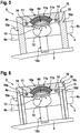
- FIG 2 shows the multirotor aircraft 1 of Figure 1 with the thrust producing units arrangement 17 that comprises the predetermined number of thrust producing units 3 and the predetermined number of structural supports 4.
- the multirotor aircraft 1 is illustrated in sectional view, only the thrust producing unit 3a that is connected to the structural support member 4a, and the thrust producing unit 3b that is connected to the structural support member 4b, are shown.
- the thrust producing units arrangement 17 is mechanically coupled to the airframe 2 by means of the flexible suspension unit 9 of Figure 1 , which is rigidly mounted to the airframe 2 of the multirotor aircraft 1. Therefore, the flexible suspension unit 9 is preferably provided with at least one bearing 11 that mechanically couples the thrust producing units arrangement 17 to the airframe 2.
- the at least one bearing 11 is an elastomeric bearing and, preferentially, a spherical elastomeric bearing.
- the thrust producing units arrangement 17 is suspended from the flexible suspension unit 9 towards the airframe 2 by means of the at least one bearing 11.
- the flexible suspension unit 9 is mechanically coupled to the thrust producing units arrangement 17 by means of the at least one bearing 11 such that the thrust producing units arrangement 17 is hanging over the airframe 2.
- the connecting structure 10 preferably comprises a connecting element 10e that is illustratively plate- or disc-shaped.
- the plate- or disc-shaped connecting element 10e is according to one aspect spaced apart from the airframe 2 by means of a predetermined number of support members that preferably includes at least two and, preferentially, four support members, from which only three support members 10a, 10b, 10d are visible in Figure 2 .
- the support members 10a, 10b, 10d (and 10c in Figure 4 ) form a table-like configuration that is rigidly mounted to the airframe 2.
- the at least one bearing 11 is arranged between the plate- or disc-shaped connecting element 10e and the thrust producing units arrangement 17. More specifically, the at least one bearing 11 is arranged between a side of the plate- or disc-shaped connecting element 10e that faces the airframe 2 and the structural support members 4a, 4b of the thrust producing units arrangement 17. Preferably, a broader side of the at least one bearing 11 is attached to the plate- or disc-shaped connecting element 10e.
- Figure 3 shows the flexible suspension unit 9 of Figure 2 with the at least one bearing 11 that couples the plate- or disc-shaped connecting element 10e of the connecting structure 10 to the structural support members 4a, 4b.
- the structural support members 4a, 4b are provided with a disc- or plate-shaped connecting base element 4e, which is preferentially arranged at an intersection of the structural support members 4a, 4b.
- the disc- or plate-shaped connecting base element 4e is connected to a coupling member 4d that is coupled to the at least one bearing 11.
- the coupling member 4d can be rigidly mounted to or integrally formed in one piece with the disc- or plate-shaped connecting base element 4e.
- the at least one bearing 11 preferably defines a rotation center 12 for rotation, i.e. inclination resp. tilting of the structural support members 4a, 4b and, therefore, of the thrust producing units 17 of Figure 1 and Figure 2 .
- the at least one bearing 11 provides for a rotational DoF 13 for the structural support members 4a, 4b and, therefore, for the thrust producing units arrangement 17 of Figure 1 and Figure 2 .
- the at least one bearing 11 comprises a plurality of metal layers 11a that are interleaved with a plurality of elastomeric layers 11b.
- metal layers 11a that are interleaved with a plurality of elastomeric layers 11b.
- the reference sign 11a for simplicity and clarity of the drawings, only a single metal layer is labeled with the reference sign 11a and only a single elastomeric layer is labeled with the reference sign 11b.
- Figure 4 shows the flexible suspension unit 9 with the at least one bearing 11 of Figure 2 and Figure 3 , from which the thrust producing units arrangement 17 of Figure 1 and Figure 2 is suspended.
- the flexible suspension unit 9 is provided with the connecting structure 10 of Figure 3 .
- the connecting structure 10 is illustrated in greater detail, which preferably does not only include the support members 10a, 10b, 10d of Figure 3 , but moreover an additional support member 10c. Part (A) also further illustrates the table-like configuration of the connecting structure 10.
- Figure 5 shows the flexible suspension unit 9 of Figure 3 with the at least one bearing 11 that couples the plate- or disc-shaped connecting element 10e of the connecting structure 10 to the structural support members 4a, 4b.
- the flexible suspension unit 9 is now provided with at least one and, exemplarily, two mechanical movement limiters 14 for limiting inclination of the structural support members 4a, 4b and, thus, of the thrust producing units 3a, 3b, 3c, 3d of the predetermined number of thrust producing units 3a, 3b, 3c, 3d of Figure 1 and Figure 2 in relation to the airframe 2 of Figure 1 and Figure 2 .
- the mechanical movement limiters 14 are arranged on a side of the plate- or disc-shaped connecting element 10e that faces the structural support members 4a, 4b.
- the mechanical movement limiters 14 are provided for limiting the rotational DoF 13 of Figure 3 of the structural support members 4a, 4b to an illustrative freedom of movement 15.
- the latter may be determined in an application-specific manner based on respective realization requirements, which are well-known to the person skilled in the art and, therefore, not explained in greater detail.
- FIG 6 shows the flexible suspension unit 9 of Figure 5 with the two mechanical movement limiters 14 and the at least one bearing 11 that couples the plate- or disc-shaped connecting element 10e of the connecting structure 10, which includes the support members 10a, 10b, 10d (and 10c in Figure 4 ), to the structural support members 4a, 4b.
- the flexible suspension unit 9 is now provided with at least one dampening unit 16 for dampening movement of the structural support members 4a, 4b and, thus, of the thrust producing units 3a, 3b, 3c, 3d of the predetermined number of thrust producing units 3a, 3b, 3c, 3d of Figure 1 and Figure 2 in relation to the airframe 2 of Figure 1 and Figure 2 .
- a dampening unit 16 is mounted to each one of the support members 10a, 10b, 10d (and 10c in Figure 4 ).
- two illustrative dampers 16a, 16b are mounted to the support members 10a, 10d, respectively.
- the at least one dampening unit 16 advantageously contributes to enhance passenger comfort and to reduce vibration, which could propagate from the thrust producing units 3a, 3b, 3c, 3d of the predetermined number of thrust producing units 3a, 3b, 3c, 3d of Figure 1 and Figure 2 into the airframe 2 of Figure 1 and Figure 2 .
- the flexible suspension unit 9 with the at least one bearing 11 is a passive system.
- tilting resp, inclining of the structural support members 4a, 4b and, thus, of the thrust producing units 3a, 3b, 3c, 3d of the predetermined number of thrust producing units 3a, 3b, 3c, 3d of Figure 1 and Figure 2 in relation to the airframe 2 of Figure 1 and Figure 2 is preferably not actively controlled.
- actively controlling the tilting resp. inclining of the structural support members 4a, 4b and, thus, of the thrust producing units 3a, 3b, 3c, 3d of the predetermined number of thrust producing units 3a, 3b, 3c, 3d of Figure 1 and Figure 2 in relation to the airframe 2 of Figure 1 and Figure 2 is nevertheless possible, as described hereinafter.
- the flexible suspension unit 9 is provided with at least one actuating unit for controlling inclination resp. tilting of the thrust producing units 3a, 3b, 3c, 3d of the predetermined number of thrust producing units 3a, 3b, 3c, 3d of Figure 1 and Figure 2 in relation to the airframe 2 of Figure 1 and Figure 2 .
- an actuating unit is mounted to each one of the support members 10a, 10b, 10d (and 10c in Figure 4 ).
- two illustrative actuators are mounted to the support members 10a, 10d, respectively.
- the flexible suspension unit 9 can be adapted for an active tilting resp. inclining control.
- the at least one actuating unit is illustrated by the same drawing components than the dampening units 16 and, thus, likewise labeled with the reference sign 16. This similarly applies to the actuators with respect to the dampers 16a, 16b, so that the actuators are likewise labeled with the reference signs 16a, 16b.
- the dampers and/or actuators 16a, 16b can be implemented by means of hydraulic dampers, pneumatic actuators and so on.
- the pitch attitude of the airframe 2 of Figure 1 and Figure 2 can be modified; the damping characteristics of the pneumatic cylinder are hereafter adjustable.
- use of hydraulic dampers will primarily only influence corresponding damping characteristics of the flexible suspension unit 9. This additional damping could be needed, depending on an underlying system design.
- actuators and/or dampers using other regulating principles are also possible.
- either the dampening units or the actuating units are provided.
- alternatively combined dampening and actuating units 16 are provided, which can be controlled for actuating the flexible suspension unit 9, i.e. the structural support members 4a, 4b, as required and, otherwise, be used for dampening movement of the structural support members 4a, 4b in operation.
- the dampening and/or actuating units 16 may also be required for restricting respective pitch movements of the airframe 2 of Figure 1 and Figure 2 .
- Figure 7 shows the thrust producing units arrangement 17 with the at least one bearing 11 of Figure 2 and Figure 3 in analogy to Figure 4 , part (B).
- the at least one bearing 11 is now illustratively embodied as a cylindrical elastomeric bearing.
- the cylindrical elastomeric bearing has one DoF less and possess, thus, only a single DoF.
- Figure 8 shows the multirotor aircraft 1 of Figure 1 with the airframe 2 and the thrust producing units arrangement 17 that comprises the predetermined number of thrust producing units 3 and the predetermined number of structural supports 4.
- the predetermined number of thrust producing units 3 comprises the four thrust producing units 3a, 3b, 3c, 3d and the predetermined number of structural supports 4 comprises the structural support members 4a, 4b that mechanically couple the four thrust producing units 3a, 3b, 3c, 3d to each other in an X-shaped configuration.
- each one of the four flexible suspension units 9a, 9b, 9c, 9d is configured similar to the flexible suspension unit 9 as described above, at least within predetermined manufacturing tolerances.
- each one of the flexible suspension units 9a, 9b, 9c, 9d is rigidly mounted to the airframe 2.
- each one of the four thrust producing units 3a, 3b, 3c, 3d is separately inclinable with respect to the airframe 2.
- a particular arrangement of the flexible suspension units 9a, 9b, 9c, 9d with respect to the airframe 2 can be determined in an application-specific manner based on predetermined implementation requirements.
- the flexible suspension units 9b, 9d are exemplarily arranged on top of the airframe 2
- the flexible suspension units 9a, 9c are slightly displaced with respect to the airframe 2.
- the flexible suspension units 9a, 9c may also be arranged on top of the airframe 2 and the lateral displacement is preferably acceptable as long as the flexible suspension units 9a, 9c are installed such that the structural support members 4a, 4b are suspended therefrom.
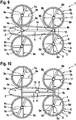
- Figure 9 shows the multirotor aircraft 1 of Figure 1 with the airframe 2 and the thrust producing units arrangement 17 that comprises the predetermined number of thrust producing units 3 and the predetermined number of structural supports 4.
- the predetermined number of thrust producing units 3 comprises the four thrust producing units 3a, 3b, 3c, 3d and the predetermined number of structural supports 4 comprises the structural support members 4a, 4b.
- the predetermined number of structural supports 4 now further comprises an additional structural support member 4c.
- the structural support members 4a, 4b, 4c mechanically couple the four thrust producing units 3a, 3b, 3c, 3d to each other in an H-shaped configuration.
- two thrust producing units 3a, 3c; 3b, 3d are mechanically coupled to each other by means of one of the structural support members 4a, 4b.
- the structural support member 4c exemplarily connects the structural support members 4a, 4b and, thus, defines the H-shaped configuration.
- each one of the structural support members 4a, 4b is embodied as an at least essentially straight beam, which is mechanically coupled to the airframe 2 by means of an associated flexible suspension unit, e.g. the flexible suspension units 9a, 9b of Figure 8 , respectively.
- an associated flexible suspension unit e.g. the flexible suspension units 9a, 9b of Figure 8 , respectively.
- at least two mechanically coupled thrust producing units 3a, 3c and 3b, 3d are now respectively mechanically coupled to the airframe 2 by means of the bearings 11.
- the structural support member 4c is preferably also embodied as an at least essentially straight beam.
- Figure 10 shows the multirotor aircraft 1 of Figure 9 with the airframe 2 and the thrust producing units arrangement 17 that comprises the predetermined number of thrust producing units 3 and the predetermined number of structural supports 4.
- the predetermined number of thrust producing units 3 comprises the four thrust producing units 3a, 3b, 3c, 3d and the predetermined number of structural supports 4 comprises the structural support members 4a, 4b, 4c, which mechanically couple the four thrust producing units 3a, 3b, 3c, 3d to each other in an H-shaped configuration.
- the thrust producing units arrangement 17 is mechanically coupled to the airframe 2 by means of an associated flexible suspension unit, illustratively the flexible suspension unit 9 of Figure 1 .
- Figure 11 shows the multirotor aircraft 1 of Figure 10 with the airframe 2 and the thrust producing units arrangement 17 that comprises the predetermined number of thrust producing units 3 and the predetermined number of structural supports 4.
- the predetermined number of structural supports 4 comprises the structural support members 4a, 4b, 4c, from which only the structural support member 4c is mechanically coupled to the airframe 2 by means of an associated flexible suspension unit, illustratively the flexible suspension unit 9 of Figure 1 . More specifically, the flexible suspension unit 9 is provided with the at least one bearing 11 of Figure 2 , from which the thrust producing units arrangement 17 is suspended via the structural support member 4c.
- the flexible suspension unit 9 is now preferably rigidly mounted to a coupling structure 17a.
- the coupling structure 17a allows detachment and removal of the thrust producing units arrangement 17 from the airframe 2, as described hereinafter with reference to Figure 12 .
- Figure 12 shows the multirotor aircraft 1 of Figure 11 with the airframe 2, the flexible suspension unit 9 and the thrust producing units arrangement 17 that comprises the predetermined number of thrust producing units 3 and the predetermined number of structural supports 4.
- the flexible suspension unit 9 is rigidly mounted to the coupling structure 17a of Figure 11 in order to allow detachment and removal of the thrust producing units arrangement 17 from the airframe 2.
- the coupling structure 17a is equipped with two attachment plates 17b, 17c.
- the attachment plate 17b is rigidly mounted to the flexible suspension unit 9, and the attachment plate 17c is rigidly mounted to the airframe 2.
- the attachment plate 17b can be mounted detachably to the attachment plate 17c, such that the flexible suspension unit 9 is detachably mounted to the airframe 2.
- the thrust producing units arrangement 17 is illustrated in detached state. This detached state can be advantageous for maintenance or replacement, but also e.g. for recharging of electric power sources of the thrust producing units arrangement 17, and so on.
- Figure 13 shows the multirotor aircraft 1 of Figure 1 with the airframe 2, the flexible suspension unit 9, and the thrust producing units arrangement 17 that comprises the predetermined number of thrust producing units 3 and the predetermined number of structural supports 4.
- the thrust producing units arrangement 17 is suspended over the airframe 2 by means of the flexible suspension unit 9, which only exemplarily comprises the dampening and/or actuating units 16 of Figure 6 .
- multirotor aircraft 1 is only represented schematically for explaining an exemplary operation in forward flight thereof. However, this representation is not illustrative of a preferred realization of the multirotor aircraft 1 and, in particular, not for a particular realization of the flexible suspension unit 9, which is shown in Figure 2 to Figure 7 .
- the multirotor aircraft 1 in forward flight of the multirotor aircraft 1, the latter is operated in a free airstream with a free airstream direction 18.
- the predetermined number of thrust producing units 3 In order to move in a direction that is opposed to the free airstream direction 18, the predetermined number of thrust producing units 3 generates thrust in a predetermined direction that is indicated with thrust vectors 19.
- the thrust resp. the thrust vectors 19 respectively comprise a lift component 19a and a propulsion component 19b.
- the lift component 19a is responsible for maintaining the multirotor aircraft 1 in the air, i.e. in flying state, against a gravitational force, to which the multirotor aircraft 1 is subjected and which is illustrated by an arrow 19c.
- the propulsion component 19b is responsible for moving resp. pushing the multirotor aircraft 1 into forward flight direction, i.e. illustratively into a direction that is opposed to the free airstream direction 18, which creates aerodynamic drag 19d on the multirotor aircraft 1.
- the propulsion component 19b of the thrust vectors 19 is only created if the predetermined number of thrust producing units 3 is inclined. According to the present invention, this is achieved by tilting resp. inclining the predetermined number of thrust producing units 3, i.e. the thrust producing units arrangement 17, by an associated inclination angle 20 in relation to the airframe 2.
- Figure 14 shows a multirotor aircraft 21 with the airframe 2 of Figure 1 and the thrust producing units arrangement 17 of Figure 1 that comprises the predetermined number of thrust producing units 3 of Figure 1 and the predetermined number of structural supports 4 of Figure 1 .
- a fixed attachment unit 22 is provided that fixedly attaches the thrust producing units arrangement 17 to the airframe 2 in a manner that does not allow tilting resp. inclining of the thrust producing units arrangement 17 in relation to the airframe 2.
- the multirotor aircraft 21 is only represented schematically for explaining operation in forward flight thereof. However, this representation is not illustrative of a possible realization of the multirotor aircraft 21 and, in particular, not for a particular realization of the fixed attachment unit 22.
- the multirotor aircraft 21 is operated in forward flight in a free airstream with the free airstream direction 18 of Figure 13 and the predetermined number of thrust producing units 3 generates thrust in a predetermined direction that is indicated with the thrust vectors 19 of Figure 13 .
- the thrust resp. the thrust vectors 19 respectively comprise the lift component 19a of Figure 13 and the propulsion component 19b of Figure 13 .
- the lift component 19a is responsible for maintaining the multirotor aircraft 21 in the air, i.e. in flying state, against a gravitational force, to which the multirotor aircraft 21 is subjected and which is illustrated by the arrow 19c of Figure 13 .
- the propulsion component 19b is responsible for moving resp. pushing the multirotor aircraft 21 into forward flight direction, i.e. illustratively into a direction that is opposed to the free airstream direction 18, which creates aerodynamic drag 19e on the multirotor aircraft 21.
- the propulsion component 19b of the thrust vectors 19 is only created if the predetermined number of thrust producing units 3 is inclined.
- the thrust producing units arrangement 17 is fixedly attached to the airframe 2, this is achieved by inclining the entire multirotor aircraft 21 as required.
- the entire multirotor aircraft 21 is inclined by the associated inclination angle 20 of Figure 13 .
- the inclination of the thrust producing units arrangement 17 is exemplarily identical in Figure 13 and Figure 14 .
- the airframe 2 is not inclined
- the entire multirotor aircraft 21 is inclined and the aerodynamic drag 19e which is accordingly created is, thus, significantly greater than the aerodynamic drag 19d of Figure 13 . Consequently, a respectively required power supply for operation of the multirotor aircraft 21 is significantly greater than a respectively required power supply for operation of the multirotor aircraft 1 according to Figure 13 .
Claims (8)
- Aéronef multi-rotor (1) avec une cellule (2) et un agencement d'unités de production de poussée (17), dans lequel la cellule (2) définit un volume interne (2a) qui est au moins adapté pour le transport de passagers, et dans lequel l'agencement d'unités de production de poussée (17) comprend un nombre prédéterminé d'unités de production de poussée (3a, 3b, 3c, 3d) pour produire une poussée dans une direction prédéterminée (19), dans lequel une unité de suspension flexible (9) est montée de façon rigide sur la cellule (2), et dans lequel l'unité de suspension flexible (9) comprend au moins un palier (11) qui couple mécaniquement l'agencement d'unités de production de poussée (17) à la cellule (2) de façon que les unités de production de poussée (3a, 3b, 3c, 3d) du nombre prédéterminé d'unités de production de poussée (3a, 3b, 3c, 3d) soient inclinables par rapport à la cellule (2), caractérisé en ce que l'unité de suspension flexible (9) comprend une structure de raccordement (10) sur laquelle l'agencement d'unités de production de poussée (17) est attaché vers la cellule (2) à l'aide du au moins un palier (11) de façon que l'agencement d'unités de production de poussée (17) soit disposé en surplomb de la cellule (2), dans lequel le au moins un palier (11) est un palier en élastomère sphérique ou un palier en élastomère cylindrique, et dans lequel le nombre prédéterminé d'unités de production de poussée (3a, 3b, 3c, 3d) comprend au moins deux unités de production de poussée (3a, 3c ; 3b, 3d) couplées mécaniquement qui sont couplées mécaniquement à la cellule (2) à l'aide du au moins un palier (11).
- Aéronef multi-rotor (1) selon la revendication 1,
caractérisé en ce que le nombre prédéterminé d'unités de production de poussée (3a, 3b, 3c, 3d) comprend quatre unités de production de poussée (3a, 3b, 3c, 3d) qui sont couplées mécaniquement l'une à l'autre dans une configuration à forme en H, dans lequel deux unités de production de poussée (3a, 3c ; 3b, 3d) sont respectivement couplées l'une à l'autre à l'aide d'un élément de support structurel au moins essentiellement droit (4a ; 4b), et dans lequel la configuration à forme en H est couplée mécaniquement à la cellule (2) à l'aide du au moins un palier (11). - Aéronef multi-rotor (1) selon la revendication 2,
caractérisé en ce que chaque élément de support structurel au moins essentiellement droit (4a ; 4b) est couplé mécaniquement à la cellule (2) à l'aide d'au moins un palier associé (11). - Aéronef multi-rotor (1) selon la revendication 1,
caractérisé en ce que le nombre prédéterminé d'unités de production de poussée (3a, 3b, 3c, 3d) comprend quatre unités de production de poussée (3a, 3b, 3c, 3d) qui sont couplées mécaniquement l'une à l'autre dans une configuration à forme en X, dans lequel la configuration à forme en X est couplée mécaniquement à la cellule (2) à l'aide du au moins un palier (11). - Aéronef multi-rotor (1) selon la revendication 1,
caractérisé en ce que l'unité de suspension flexible (9) comprend au moins un limiteur mécanique de mouvement (14) pour limiter l'inclinaison des unités de production de poussée (3a, 3b, 3c, 3d) du nombre prédéterminé d'unités de production de poussée (3a, 3b, 3c, 3d) par rapport à la cellule (2). - Aéronef multi-rotor (1) selon la revendication 1,
caractérisé en ce que l'unité de suspension flexible (9) comprend au moins une unité d'amortissement (16) pour amortir le mouvement des unités de production de poussée (3a, 3b, 3c, 3d) du nombre prédéterminé d'unités de production de poussée (3a, 3b, 3c, 3d) par rapport à la cellule (2). - Aéronef multi-rotor (1) selon la revendication 1,
caractérisé en ce que l'unité de suspension flexible (9) comprend au moins une unité d'actionnement (16) pour commander l'inclinaison des unités de production de poussée (3a, 3b, 3c, 3d) du nombre prédéterminé d'unités de production de poussée (3a, 3b, 3c, 3d) par rapport à la cellule (2). - Aéronef multi-rotor (1) selon la revendication 1,
caractérisé en ce que l'unité de suspension flexible (9) est montée de façon détachable sur la cellule (2).
Priority Applications (4)
| Application Number | Priority Date | Filing Date | Title |
|---|---|---|---|
| EP17400009.1A EP3366582B1 (fr) | 2017-02-28 | 2017-02-28 | Aéronef multirotor ayant une cellule et un agencement d'unités de production de poussée |
| MX2018000884A MX2018000884A (es) | 2017-02-28 | 2018-01-19 | Una aeronave multirotor con un fuselaje y un acomodo de unidades de produccion de empuje. |
| CN201810156859.XA CN108502152B (zh) | 2017-02-28 | 2018-02-24 | 具有机体和推力产生单元装置的多旋翼飞行器 |
| US15/906,227 US10933987B2 (en) | 2017-02-28 | 2018-02-27 | Multirotor aircraft with an airframe and a thrust producing units arrangement |
Applications Claiming Priority (1)
| Application Number | Priority Date | Filing Date | Title |
|---|---|---|---|
| EP17400009.1A EP3366582B1 (fr) | 2017-02-28 | 2017-02-28 | Aéronef multirotor ayant une cellule et un agencement d'unités de production de poussée |
Publications (2)
| Publication Number | Publication Date |
|---|---|
| EP3366582A1 EP3366582A1 (fr) | 2018-08-29 |
| EP3366582B1 true EP3366582B1 (fr) | 2019-07-24 |
Family
ID=58401526
Family Applications (1)
| Application Number | Title | Priority Date | Filing Date |
|---|---|---|---|
| EP17400009.1A Active EP3366582B1 (fr) | 2017-02-28 | 2017-02-28 | Aéronef multirotor ayant une cellule et un agencement d'unités de production de poussée |
Country Status (4)
| Country | Link |
|---|---|
| US (1) | US10933987B2 (fr) |
| EP (1) | EP3366582B1 (fr) |
| CN (1) | CN108502152B (fr) |
| MX (1) | MX2018000884A (fr) |
Cited By (1)
| Publication number | Priority date | Publication date | Assignee | Title |
|---|---|---|---|---|
| RU2730784C1 (ru) * | 2019-12-06 | 2020-08-26 | Александр Викторович Атаманов | Система электропитания летательного аппарата вертикального взлета и посадки |
Families Citing this family (23)
| Publication number | Priority date | Publication date | Assignee | Title |
|---|---|---|---|---|
| KR101554487B1 (ko) * | 2013-12-23 | 2015-09-21 | 이상현 | 멀티 로터 비행체 |
| US11634211B2 (en) * | 2017-06-07 | 2023-04-25 | Joseph R. Renteria | Aircraft with linear thruster arrangement |
| US11161605B2 (en) * | 2017-08-10 | 2021-11-02 | Kawasaki Jukogyo Kabushiki Kaisha | Air vehicle and method of controlling air vehicle |
| WO2019073417A1 (fr) * | 2017-10-11 | 2019-04-18 | Hangzhou Zero Zero Technology Co., Ltd. | Système aérien comprenant une architecture de cadre pliable |
| WO2019109306A1 (fr) * | 2017-12-07 | 2019-06-13 | 深圳市大疆创新科技有限公司 | Véhicule aérien sans pilote |
| GB201802611D0 (en) * | 2018-02-17 | 2018-04-04 | Panelplane Ltd | Teleporter |
| WO2020016890A1 (fr) * | 2018-07-16 | 2020-01-23 | Gal Solar Fields Ltd | Système de vol doté d'un lanceur de charge utile |
| US10946956B2 (en) * | 2018-08-30 | 2021-03-16 | Textron Innovations Inc. | Unmanned aerial systems having out of phase gimballing axes |
| RU2696051C1 (ru) * | 2018-09-07 | 2019-07-30 | Виктор Израилевич Думов | Аэроэлектроподъемный летательный аппарат |
| US10787255B2 (en) | 2018-11-30 | 2020-09-29 | Sky Canoe Inc. | Aerial vehicle with enhanced pitch control and interchangeable components |
| DK3659912T3 (da) * | 2018-11-30 | 2022-04-25 | Umiles Urban Air Mobility S L | Luftfartøjer med afkoblede frihedsgrader |
| CN110641692A (zh) * | 2018-12-14 | 2020-01-03 | 深圳市格上格创新科技有限公司 | 机身平衡无人机及其控制方法 |
| JP7181643B2 (ja) * | 2018-12-14 | 2022-12-01 | 国立研究開発法人宇宙航空研究開発機構 | 飛翔体 |
| CN110641680B (zh) * | 2018-12-18 | 2021-07-23 | 深圳市格上格创新科技有限公司 | 可折叠多旋翼无人机 |
| RU2019115086A (ru) * | 2019-02-06 | 2020-11-16 | ООО "Миландр СМ" | Мультироторный летательный аппарат |
| EP3702277B1 (fr) | 2019-02-27 | 2021-01-27 | AIRBUS HELICOPTERS DEUTSCHLAND GmbH | Aéronef multirotor adapté pour décollage et atterrissage verticaux (adav) |
| EP3702276B1 (fr) | 2019-02-27 | 2021-01-13 | AIRBUS HELICOPTERS DEUTSCHLAND GmbH | Aéronef multirotor à aile jointe avec des capacités de décollage et atterrissage verticaux (adav) |
| CA3135682A1 (fr) * | 2019-04-01 | 2020-10-08 | Olivier Lamaille | Appareil pour la navigation aerienne et ses dispositifs |
| CN110053768A (zh) * | 2019-05-08 | 2019-07-26 | 沈阳无距科技有限公司 | 无人机 |
| EP3741672A1 (fr) * | 2019-05-24 | 2020-11-25 | Antonov Engineering GmbH | Hélicoptère |
| CN112173117A (zh) * | 2020-09-12 | 2021-01-05 | 广东寻夏科技有限公司 | 一种具有投放功能的多旋翼飞行器及其控制方法 |
| DE102020127029B3 (de) | 2020-10-14 | 2021-09-30 | Dr. Ing. H.C. F. Porsche Aktiengesellschaft | Mantelpropeller eines Luftfahrzeugs und Luftfahrzeug |
| CN112373686B (zh) * | 2020-11-26 | 2022-07-08 | 尚良仲毅(沈阳)高新科技有限公司 | 一种无人机及其矢量角度控制方法 |
Family Cites Families (30)
| Publication number | Priority date | Publication date | Assignee | Title |
|---|---|---|---|---|
| GB905911A (en) | 1957-11-19 | 1962-09-12 | Maurice Louis Hurel | Improvements in aircraft having a lift producing rotor disposed in a supporting surface |
| US4212588A (en) * | 1978-05-11 | 1980-07-15 | United Technologies Corporation | Simplified rotor head fairing |
| US4771967A (en) | 1986-06-17 | 1988-09-20 | Geldbaugh G Richard | Rotor aircraft |
| US6568630B2 (en) | 2001-08-21 | 2003-05-27 | Urban Aeronautics Ltd. | Ducted vehicles particularly useful as VTOL aircraft |
| US7032861B2 (en) | 2002-01-07 | 2006-04-25 | Sanders Jr John K | Quiet vertical takeoff and landing aircraft using ducted, magnetic induction air-impeller rotors |
| US7857253B2 (en) | 2003-10-27 | 2010-12-28 | Urban Aeronautics Ltd. | Ducted fan VTOL vehicles |
| US7946528B2 (en) | 2005-04-15 | 2011-05-24 | Urban Aeronautics, Ltd. | Flight control system especially suited for VTOL vehicles |
| DE102005022706A1 (de) | 2005-05-18 | 2006-11-23 | Dolch, Stefan, Dipl.-Ing. (FH) | Hubschrauber mit einer Kamera |
| US20100270419A1 (en) | 2007-12-14 | 2010-10-28 | Raphael Yoeli | Redundancies and flows in vehicles |
| CN201306711Y (zh) | 2008-11-04 | 2009-09-09 | 王国良 | 二甲醚环保节能专用燃烧器 |
| US20110042510A1 (en) | 2009-08-24 | 2011-02-24 | Bevirt Joeben | Lightweight Vertical Take-Off and Landing Aircraft and Flight Control Paradigm Using Thrust Differentials |
| JP5421503B2 (ja) | 2010-07-19 | 2014-02-19 | ズィー.エアロ インコーポレイテッド | 自家用航空機 |
| US9187174B2 (en) * | 2010-10-06 | 2015-11-17 | Donald Orval Shaw | Aircraft with wings and movable propellers |
| EP2551193B1 (fr) | 2011-07-29 | 2016-04-13 | AGUSTAWESTLAND S.p.A. | Avion convertible |
| PT2551190E (pt) | 2011-07-29 | 2014-01-23 | Agustawestland Spa | Avião convertível |
| PT2551198E (pt) | 2011-07-29 | 2013-12-27 | Agustawestland Spa | Avião convertível |
| USD678169S1 (en) | 2011-09-19 | 2013-03-19 | Zee.Aero Inc. | Aircraft |
| US8602942B2 (en) | 2011-11-16 | 2013-12-10 | Zee.Aero Inc. | Centrifugal de-clutch |
| DE102013108207A1 (de) | 2013-07-31 | 2015-02-05 | E-Volo Gmbh | Fluggerät, insbesondere Multicopter |
| DE102013109392A1 (de) | 2013-08-29 | 2015-03-05 | Airbus Defence and Space GmbH | Schnellfliegendes, senkrechtstartfähiges Fluggerät |
| US20150127209A1 (en) | 2013-11-05 | 2015-05-07 | King Fahd University Of Petroleum And Minerals | Bird repellent system |
| CN104627360A (zh) * | 2013-11-07 | 2015-05-20 | 李宏富 | H型结构的直升机 |
| KR101554487B1 (ko) | 2013-12-23 | 2015-09-21 | 이상현 | 멀티 로터 비행체 |
| US9873507B2 (en) * | 2014-02-26 | 2018-01-23 | Bell Helicopter Textron Inc. | Rotorcraft elastomeric bearing assembly |
| KR101451646B1 (ko) | 2014-07-16 | 2014-10-16 | (주)테크맥스텔레콤 | 다기능 덕트형 무인비행체 |
| IL234443B (en) * | 2014-09-02 | 2019-03-31 | Regev Amit | Swing-wing multi-bladed rifle |
| US9946267B2 (en) * | 2015-04-06 | 2018-04-17 | Thomas A. Youmans | Control and stabilization of a flight vehicle from a detected perturbation by tilt and rotation |
| CN104859851A (zh) * | 2015-04-27 | 2015-08-26 | 刘朝阳 | 由带导流舵的涵道升力风扇驱动的多旋翼飞行器 |
| CN105539829B (zh) | 2015-12-24 | 2017-09-15 | 刘海涛 | 多旋翼飞行器 |
| CN106379520B (zh) * | 2016-09-14 | 2018-10-12 | 南京灵雀智能制造有限公司 | 一种智能载人飞行器 |
-
2017
- 2017-02-28 EP EP17400009.1A patent/EP3366582B1/fr active Active
-
2018
- 2018-01-19 MX MX2018000884A patent/MX2018000884A/es unknown
- 2018-02-24 CN CN201810156859.XA patent/CN108502152B/zh active Active
- 2018-02-27 US US15/906,227 patent/US10933987B2/en active Active
Non-Patent Citations (1)
| Title |
|---|
| None * |
Cited By (1)
| Publication number | Priority date | Publication date | Assignee | Title |
|---|---|---|---|---|
| RU2730784C1 (ru) * | 2019-12-06 | 2020-08-26 | Александр Викторович Атаманов | Система электропитания летательного аппарата вертикального взлета и посадки |
Also Published As
| Publication number | Publication date |
|---|---|
| CN108502152A (zh) | 2018-09-07 |
| CN108502152B (zh) | 2021-08-24 |
| US10933987B2 (en) | 2021-03-02 |
| MX2018000884A (es) | 2018-11-09 |
| EP3366582A1 (fr) | 2018-08-29 |
| US20180265189A1 (en) | 2018-09-20 |
Similar Documents
| Publication | Publication Date | Title |
|---|---|---|
| EP3366582B1 (fr) | Aéronef multirotor ayant une cellule et un agencement d'unités de production de poussée | |
| US11554862B2 (en) | Vertical take-off and landing multirotor aircraft with at least eight thrust producing units | |
| CN111247066B (zh) | 用于电动竖直起降(vtol)航空器的机翼倾斜致动系统 | |
| EP3354560B1 (fr) | Unité de production de poussée avec au moins deux ensembles rotor et un carénage | |
| US8708273B2 (en) | Three-wing, six tilt-propulsion unit, VTOL aircraft | |
| US8800912B2 (en) | Three wing, six-tilt propulsion unit, VTOL aircraft | |
| US8616492B2 (en) | Three wing, six tilt-propulsion units, VTOL aircraft | |
| EP3000722B1 (fr) | Avion | |
| EP1999016B1 (fr) | Aeronef convertible | |
| US10836475B2 (en) | Multirotor aircraft with an airframe and at least one wing | |
| US6402088B1 (en) | Passenger vehicle employing a circumferentially disposed rotatable thrust assembly | |
| US8857755B2 (en) | Vertical/short take-off and landing passenger aircraft | |
| EP1775214A1 (fr) | Dispositif de changement de direction du vent et de génération rapide d'une quantité d'air et avion disposant du dispositif fixé sur la face latérale d'une cellule | |
| EP2625094A1 (fr) | Avion adav à trois ailes et six unités de propulsion inclinables | |
| JP2020535051A (ja) | 回転ポール上の推進装置を有する回転翼航空機 | |
| EP3770063B1 (fr) | Aéronef multirotor ayant des rotors carénés | |
| US11814162B2 (en) | Rotatable winglets for a rotary wing aircraft |
Legal Events
| Date | Code | Title | Description |
|---|---|---|---|
| PUAI | Public reference made under article 153(3) epc to a published international application that has entered the european phase |
Free format text: ORIGINAL CODE: 0009012 |
|
| STAA | Information on the status of an ep patent application or granted ep patent |
Free format text: STATUS: THE APPLICATION HAS BEEN PUBLISHED |
|
| STAA | Information on the status of an ep patent application or granted ep patent |
Free format text: STATUS: REQUEST FOR EXAMINATION WAS MADE |
|
| AK | Designated contracting states |
Kind code of ref document: A1 Designated state(s): AL AT BE BG CH CY CZ DE DK EE ES FI FR GB GR HR HU IE IS IT LI LT LU LV MC MK MT NL NO PL PT RO RS SE SI SK SM TR |
|
| AX | Request for extension of the european patent |
Extension state: BA ME |
|
| 17P | Request for examination filed |
Effective date: 20180807 |
|
| RBV | Designated contracting states (corrected) |
Designated state(s): AL AT BE BG CH CY CZ DE DK EE ES FI FR GB GR HR HU IE IS IT LI LT LU LV MC MK MT NL NO PL PT RO RS SE SI SK SM TR |
|
| STAA | Information on the status of an ep patent application or granted ep patent |
Free format text: STATUS: EXAMINATION IS IN PROGRESS |
|
| 17Q | First examination report despatched |
Effective date: 20181120 |
|
| GRAP | Despatch of communication of intention to grant a patent |
Free format text: ORIGINAL CODE: EPIDOSNIGR1 |
|
| STAA | Information on the status of an ep patent application or granted ep patent |
Free format text: STATUS: GRANT OF PATENT IS INTENDED |
|
| INTG | Intention to grant announced |
Effective date: 20190402 |
|
| GRAJ | Information related to disapproval of communication of intention to grant by the applicant or resumption of examination proceedings by the epo deleted |
Free format text: ORIGINAL CODE: EPIDOSDIGR1 |
|
| STAA | Information on the status of an ep patent application or granted ep patent |
Free format text: STATUS: EXAMINATION IS IN PROGRESS |
|
| GRAR | Information related to intention to grant a patent recorded |
Free format text: ORIGINAL CODE: EPIDOSNIGR71 |
|
| GRAS | Grant fee paid |
Free format text: ORIGINAL CODE: EPIDOSNIGR3 |
|
| STAA | Information on the status of an ep patent application or granted ep patent |
Free format text: STATUS: GRANT OF PATENT IS INTENDED |
|
| GRAA | (expected) grant |
Free format text: ORIGINAL CODE: 0009210 |
|
| STAA | Information on the status of an ep patent application or granted ep patent |
Free format text: STATUS: THE PATENT HAS BEEN GRANTED |
|
| INTC | Intention to grant announced (deleted) | ||
| AK | Designated contracting states |
Kind code of ref document: B1 Designated state(s): AL AT BE BG CH CY CZ DE DK EE ES FI FR GB GR HR HU IE IS IT LI LT LU LV MC MK MT NL NO PL PT RO RS SE SI SK SM TR |
|
| INTG | Intention to grant announced |
Effective date: 20190614 |
|
| REG | Reference to a national code |
Ref country code: GB Ref legal event code: FG4D |
|
| REG | Reference to a national code |
Ref country code: CH Ref legal event code: EP |
|
| REG | Reference to a national code |
Ref country code: DE Ref legal event code: R096 Ref document number: 602017005554 Country of ref document: DE |
|
| REG | Reference to a national code |
Ref country code: AT Ref legal event code: REF Ref document number: 1157866 Country of ref document: AT Kind code of ref document: T Effective date: 20190815 |
|
| REG | Reference to a national code |
Ref country code: IE Ref legal event code: FG4D |
|
| REG | Reference to a national code |
Ref country code: NL Ref legal event code: MP Effective date: 20190724 |
|
| REG | Reference to a national code |
Ref country code: LT Ref legal event code: MG4D |
|
| REG | Reference to a national code |
Ref country code: AT Ref legal event code: MK05 Ref document number: 1157866 Country of ref document: AT Kind code of ref document: T Effective date: 20190724 |
|
| PG25 | Lapsed in a contracting state [announced via postgrant information from national office to epo] |
Ref country code: NO Free format text: LAPSE BECAUSE OF FAILURE TO SUBMIT A TRANSLATION OF THE DESCRIPTION OR TO PAY THE FEE WITHIN THE PRESCRIBED TIME-LIMIT Effective date: 20191024 Ref country code: BG Free format text: LAPSE BECAUSE OF FAILURE TO SUBMIT A TRANSLATION OF THE DESCRIPTION OR TO PAY THE FEE WITHIN THE PRESCRIBED TIME-LIMIT Effective date: 20191024 Ref country code: AT Free format text: LAPSE BECAUSE OF FAILURE TO SUBMIT A TRANSLATION OF THE DESCRIPTION OR TO PAY THE FEE WITHIN THE PRESCRIBED TIME-LIMIT Effective date: 20190724 Ref country code: PT Free format text: LAPSE BECAUSE OF FAILURE TO SUBMIT A TRANSLATION OF THE DESCRIPTION OR TO PAY THE FEE WITHIN THE PRESCRIBED TIME-LIMIT Effective date: 20191125 Ref country code: NL Free format text: LAPSE BECAUSE OF FAILURE TO SUBMIT A TRANSLATION OF THE DESCRIPTION OR TO PAY THE FEE WITHIN THE PRESCRIBED TIME-LIMIT Effective date: 20190724 Ref country code: HR Free format text: LAPSE BECAUSE OF FAILURE TO SUBMIT A TRANSLATION OF THE DESCRIPTION OR TO PAY THE FEE WITHIN THE PRESCRIBED TIME-LIMIT Effective date: 20190724 Ref country code: LT Free format text: LAPSE BECAUSE OF FAILURE TO SUBMIT A TRANSLATION OF THE DESCRIPTION OR TO PAY THE FEE WITHIN THE PRESCRIBED TIME-LIMIT Effective date: 20190724 Ref country code: FI Free format text: LAPSE BECAUSE OF FAILURE TO SUBMIT A TRANSLATION OF THE DESCRIPTION OR TO PAY THE FEE WITHIN THE PRESCRIBED TIME-LIMIT Effective date: 20190724 Ref country code: SE Free format text: LAPSE BECAUSE OF FAILURE TO SUBMIT A TRANSLATION OF THE DESCRIPTION OR TO PAY THE FEE WITHIN THE PRESCRIBED TIME-LIMIT Effective date: 20190724 |
|
| PG25 | Lapsed in a contracting state [announced via postgrant information from national office to epo] |
Ref country code: AL Free format text: LAPSE BECAUSE OF FAILURE TO SUBMIT A TRANSLATION OF THE DESCRIPTION OR TO PAY THE FEE WITHIN THE PRESCRIBED TIME-LIMIT Effective date: 20190724 Ref country code: GR Free format text: LAPSE BECAUSE OF FAILURE TO SUBMIT A TRANSLATION OF THE DESCRIPTION OR TO PAY THE FEE WITHIN THE PRESCRIBED TIME-LIMIT Effective date: 20191025 Ref country code: IS Free format text: LAPSE BECAUSE OF FAILURE TO SUBMIT A TRANSLATION OF THE DESCRIPTION OR TO PAY THE FEE WITHIN THE PRESCRIBED TIME-LIMIT Effective date: 20191124 Ref country code: RS Free format text: LAPSE BECAUSE OF FAILURE TO SUBMIT A TRANSLATION OF THE DESCRIPTION OR TO PAY THE FEE WITHIN THE PRESCRIBED TIME-LIMIT Effective date: 20190724 Ref country code: ES Free format text: LAPSE BECAUSE OF FAILURE TO SUBMIT A TRANSLATION OF THE DESCRIPTION OR TO PAY THE FEE WITHIN THE PRESCRIBED TIME-LIMIT Effective date: 20190724 Ref country code: LV Free format text: LAPSE BECAUSE OF FAILURE TO SUBMIT A TRANSLATION OF THE DESCRIPTION OR TO PAY THE FEE WITHIN THE PRESCRIBED TIME-LIMIT Effective date: 20190724 |
|
| PG25 | Lapsed in a contracting state [announced via postgrant information from national office to epo] |
Ref country code: TR Free format text: LAPSE BECAUSE OF FAILURE TO SUBMIT A TRANSLATION OF THE DESCRIPTION OR TO PAY THE FEE WITHIN THE PRESCRIBED TIME-LIMIT Effective date: 20190724 |
|
| PG25 | Lapsed in a contracting state [announced via postgrant information from national office to epo] |
Ref country code: RO Free format text: LAPSE BECAUSE OF FAILURE TO SUBMIT A TRANSLATION OF THE DESCRIPTION OR TO PAY THE FEE WITHIN THE PRESCRIBED TIME-LIMIT Effective date: 20190724 Ref country code: IT Free format text: LAPSE BECAUSE OF FAILURE TO SUBMIT A TRANSLATION OF THE DESCRIPTION OR TO PAY THE FEE WITHIN THE PRESCRIBED TIME-LIMIT Effective date: 20190724 Ref country code: DK Free format text: LAPSE BECAUSE OF FAILURE TO SUBMIT A TRANSLATION OF THE DESCRIPTION OR TO PAY THE FEE WITHIN THE PRESCRIBED TIME-LIMIT Effective date: 20190724 Ref country code: PL Free format text: LAPSE BECAUSE OF FAILURE TO SUBMIT A TRANSLATION OF THE DESCRIPTION OR TO PAY THE FEE WITHIN THE PRESCRIBED TIME-LIMIT Effective date: 20190724 Ref country code: EE Free format text: LAPSE BECAUSE OF FAILURE TO SUBMIT A TRANSLATION OF THE DESCRIPTION OR TO PAY THE FEE WITHIN THE PRESCRIBED TIME-LIMIT Effective date: 20190724 |
|
| PG25 | Lapsed in a contracting state [announced via postgrant information from national office to epo] |
Ref country code: CZ Free format text: LAPSE BECAUSE OF FAILURE TO SUBMIT A TRANSLATION OF THE DESCRIPTION OR TO PAY THE FEE WITHIN THE PRESCRIBED TIME-LIMIT Effective date: 20190724 Ref country code: SK Free format text: LAPSE BECAUSE OF FAILURE TO SUBMIT A TRANSLATION OF THE DESCRIPTION OR TO PAY THE FEE WITHIN THE PRESCRIBED TIME-LIMIT Effective date: 20190724 Ref country code: IS Free format text: LAPSE BECAUSE OF FAILURE TO SUBMIT A TRANSLATION OF THE DESCRIPTION OR TO PAY THE FEE WITHIN THE PRESCRIBED TIME-LIMIT Effective date: 20200224 Ref country code: SM Free format text: LAPSE BECAUSE OF FAILURE TO SUBMIT A TRANSLATION OF THE DESCRIPTION OR TO PAY THE FEE WITHIN THE PRESCRIBED TIME-LIMIT Effective date: 20190724 |
|
| REG | Reference to a national code |
Ref country code: DE Ref legal event code: R097 Ref document number: 602017005554 Country of ref document: DE |
|
| PLBE | No opposition filed within time limit |
Free format text: ORIGINAL CODE: 0009261 |
|
| STAA | Information on the status of an ep patent application or granted ep patent |
Free format text: STATUS: NO OPPOSITION FILED WITHIN TIME LIMIT |
|
| PG2D | Information on lapse in contracting state deleted |
Ref country code: IS |
|
| 26N | No opposition filed |
Effective date: 20200603 |
|
| PG25 | Lapsed in a contracting state [announced via postgrant information from national office to epo] |
Ref country code: SI Free format text: LAPSE BECAUSE OF FAILURE TO SUBMIT A TRANSLATION OF THE DESCRIPTION OR TO PAY THE FEE WITHIN THE PRESCRIBED TIME-LIMIT Effective date: 20190724 |
|
| REG | Reference to a national code |
Ref country code: CH Ref legal event code: PL |
|
| REG | Reference to a national code |
Ref country code: BE Ref legal event code: MM Effective date: 20200229 |
|
| PG25 | Lapsed in a contracting state [announced via postgrant information from national office to epo] |
Ref country code: MC Free format text: LAPSE BECAUSE OF FAILURE TO SUBMIT A TRANSLATION OF THE DESCRIPTION OR TO PAY THE FEE WITHIN THE PRESCRIBED TIME-LIMIT Effective date: 20190724 Ref country code: LU Free format text: LAPSE BECAUSE OF NON-PAYMENT OF DUE FEES Effective date: 20200228 |
|
| PG25 | Lapsed in a contracting state [announced via postgrant information from national office to epo] |
Ref country code: CH Free format text: LAPSE BECAUSE OF NON-PAYMENT OF DUE FEES Effective date: 20200229 Ref country code: LI Free format text: LAPSE BECAUSE OF NON-PAYMENT OF DUE FEES Effective date: 20200229 |
|
| PG25 | Lapsed in a contracting state [announced via postgrant information from national office to epo] |
Ref country code: IE Free format text: LAPSE BECAUSE OF NON-PAYMENT OF DUE FEES Effective date: 20200228 |
|
| PG25 | Lapsed in a contracting state [announced via postgrant information from national office to epo] |
Ref country code: BE Free format text: LAPSE BECAUSE OF NON-PAYMENT OF DUE FEES Effective date: 20200229 |
|
| GBPC | Gb: european patent ceased through non-payment of renewal fee |
Effective date: 20210228 |
|
| PG25 | Lapsed in a contracting state [announced via postgrant information from national office to epo] |
Ref country code: GB Free format text: LAPSE BECAUSE OF NON-PAYMENT OF DUE FEES Effective date: 20210228 |
|
| PG25 | Lapsed in a contracting state [announced via postgrant information from national office to epo] |
Ref country code: MT Free format text: LAPSE BECAUSE OF FAILURE TO SUBMIT A TRANSLATION OF THE DESCRIPTION OR TO PAY THE FEE WITHIN THE PRESCRIBED TIME-LIMIT Effective date: 20190724 Ref country code: CY Free format text: LAPSE BECAUSE OF FAILURE TO SUBMIT A TRANSLATION OF THE DESCRIPTION OR TO PAY THE FEE WITHIN THE PRESCRIBED TIME-LIMIT Effective date: 20190724 |
|
| PG25 | Lapsed in a contracting state [announced via postgrant information from national office to epo] |
Ref country code: MK Free format text: LAPSE BECAUSE OF FAILURE TO SUBMIT A TRANSLATION OF THE DESCRIPTION OR TO PAY THE FEE WITHIN THE PRESCRIBED TIME-LIMIT Effective date: 20190724 |
|
| PGFP | Annual fee paid to national office [announced via postgrant information from national office to epo] |
Ref country code: FR Payment date: 20230221 Year of fee payment: 7 |
|
| PGFP | Annual fee paid to national office [announced via postgrant information from national office to epo] |
Ref country code: DE Payment date: 20230216 Year of fee payment: 7 |
|
| P01 | Opt-out of the competence of the unified patent court (upc) registered |
Effective date: 20230530 |