EP3365961B1 - Elektro-antriebssystem - Google Patents
Elektro-antriebssystem Download PDFInfo
- Publication number
- EP3365961B1 EP3365961B1 EP16790873.0A EP16790873A EP3365961B1 EP 3365961 B1 EP3365961 B1 EP 3365961B1 EP 16790873 A EP16790873 A EP 16790873A EP 3365961 B1 EP3365961 B1 EP 3365961B1
- Authority
- EP
- European Patent Office
- Prior art keywords
- segments
- electric motor
- drive system
- electric drive
- circuit board
- Prior art date
- Legal status (The legal status is an assumption and is not a legal conclusion. Google has not performed a legal analysis and makes no representation as to the accuracy of the status listed.)
- Active
Links
- 238000004146 energy storage Methods 0.000 claims description 34
- 210000000352 storage cell Anatomy 0.000 claims description 26
- 210000004027 cell Anatomy 0.000 claims description 24
- 230000004323 axial length Effects 0.000 claims description 13
- 238000004804 winding Methods 0.000 claims description 3
- 238000003475 lamination Methods 0.000 claims 1
- 238000001816 cooling Methods 0.000 description 7
- 238000009413 insulation Methods 0.000 description 5
- 238000010276 construction Methods 0.000 description 3
- 230000001276 controlling effect Effects 0.000 description 3
- 238000013461 design Methods 0.000 description 3
- 238000011161 development Methods 0.000 description 2
- 230000018109 developmental process Effects 0.000 description 2
- 230000000694 effects Effects 0.000 description 2
- 238000009434 installation Methods 0.000 description 2
- 239000007788 liquid Substances 0.000 description 2
- 238000012423 maintenance Methods 0.000 description 2
- 238000012546 transfer Methods 0.000 description 2
- 241001136792 Alle Species 0.000 description 1
- WHXSMMKQMYFTQS-UHFFFAOYSA-N Lithium Chemical compound [Li] WHXSMMKQMYFTQS-UHFFFAOYSA-N 0.000 description 1
- 230000032683 aging Effects 0.000 description 1
- 230000000712 assembly Effects 0.000 description 1
- 238000000429 assembly Methods 0.000 description 1
- 230000015556 catabolic process Effects 0.000 description 1
- 239000004020 conductor Substances 0.000 description 1
- 230000008878 coupling Effects 0.000 description 1
- 238000010168 coupling process Methods 0.000 description 1
- 238000005859 coupling reaction Methods 0.000 description 1
- 230000007547 defect Effects 0.000 description 1
- 230000002950 deficient Effects 0.000 description 1
- 238000006731 degradation reaction Methods 0.000 description 1
- 238000001514 detection method Methods 0.000 description 1
- 238000003745 diagnosis Methods 0.000 description 1
- 238000005538 encapsulation Methods 0.000 description 1
- 238000011156 evaluation Methods 0.000 description 1
- 238000011990 functional testing Methods 0.000 description 1
- 230000001939 inductive effect Effects 0.000 description 1
- 239000011810 insulating material Substances 0.000 description 1
- 239000012212 insulator Substances 0.000 description 1
- 230000010354 integration Effects 0.000 description 1
- 229910052744 lithium Inorganic materials 0.000 description 1
- 238000005259 measurement Methods 0.000 description 1
- 229910052751 metal Inorganic materials 0.000 description 1
- 239000002184 metal Substances 0.000 description 1
- 238000000034 method Methods 0.000 description 1
- 238000012544 monitoring process Methods 0.000 description 1
- 229920000642 polymer Polymers 0.000 description 1
- 230000001105 regulatory effect Effects 0.000 description 1
- 230000011218 segmentation Effects 0.000 description 1
- 230000003068 static effect Effects 0.000 description 1
- 230000001360 synchronised effect Effects 0.000 description 1
Images
Classifications
-
- H—ELECTRICITY
- H02—GENERATION; CONVERSION OR DISTRIBUTION OF ELECTRIC POWER
- H02K—DYNAMO-ELECTRIC MACHINES
- H02K11/00—Structural association of dynamo-electric machines with electric components or with devices for shielding, monitoring or protection
- H02K11/0094—Structural association with other electrical or electronic devices
-
- B—PERFORMING OPERATIONS; TRANSPORTING
- B60—VEHICLES IN GENERAL
- B60K—ARRANGEMENT OR MOUNTING OF PROPULSION UNITS OR OF TRANSMISSIONS IN VEHICLES; ARRANGEMENT OR MOUNTING OF PLURAL DIVERSE PRIME-MOVERS IN VEHICLES; AUXILIARY DRIVES FOR VEHICLES; INSTRUMENTATION OR DASHBOARDS FOR VEHICLES; ARRANGEMENTS IN CONNECTION WITH COOLING, AIR INTAKE, GAS EXHAUST OR FUEL SUPPLY OF PROPULSION UNITS IN VEHICLES
- B60K1/00—Arrangement or mounting of electrical propulsion units
- B60K1/04—Arrangement or mounting of electrical propulsion units of the electric storage means for propulsion
-
- B—PERFORMING OPERATIONS; TRANSPORTING
- B60—VEHICLES IN GENERAL
- B60L—PROPULSION OF ELECTRICALLY-PROPELLED VEHICLES; SUPPLYING ELECTRIC POWER FOR AUXILIARY EQUIPMENT OF ELECTRICALLY-PROPELLED VEHICLES; ELECTRODYNAMIC BRAKE SYSTEMS FOR VEHICLES IN GENERAL; MAGNETIC SUSPENSION OR LEVITATION FOR VEHICLES; MONITORING OPERATING VARIABLES OF ELECTRICALLY-PROPELLED VEHICLES; ELECTRIC SAFETY DEVICES FOR ELECTRICALLY-PROPELLED VEHICLES
- B60L50/00—Electric propulsion with power supplied within the vehicle
- B60L50/50—Electric propulsion with power supplied within the vehicle using propulsion power supplied by batteries or fuel cells
- B60L50/60—Electric propulsion with power supplied within the vehicle using propulsion power supplied by batteries or fuel cells using power supplied by batteries
- B60L50/64—Constructional details of batteries specially adapted for electric vehicles
-
- B—PERFORMING OPERATIONS; TRANSPORTING
- B60—VEHICLES IN GENERAL
- B60L—PROPULSION OF ELECTRICALLY-PROPELLED VEHICLES; SUPPLYING ELECTRIC POWER FOR AUXILIARY EQUIPMENT OF ELECTRICALLY-PROPELLED VEHICLES; ELECTRODYNAMIC BRAKE SYSTEMS FOR VEHICLES IN GENERAL; MAGNETIC SUSPENSION OR LEVITATION FOR VEHICLES; MONITORING OPERATING VARIABLES OF ELECTRICALLY-PROPELLED VEHICLES; ELECTRIC SAFETY DEVICES FOR ELECTRICALLY-PROPELLED VEHICLES
- B60L50/00—Electric propulsion with power supplied within the vehicle
- B60L50/50—Electric propulsion with power supplied within the vehicle using propulsion power supplied by batteries or fuel cells
- B60L50/60—Electric propulsion with power supplied within the vehicle using propulsion power supplied by batteries or fuel cells using power supplied by batteries
- B60L50/66—Arrangements of batteries
-
- H—ELECTRICITY
- H01—ELECTRIC ELEMENTS
- H01M—PROCESSES OR MEANS, e.g. BATTERIES, FOR THE DIRECT CONVERSION OF CHEMICAL ENERGY INTO ELECTRICAL ENERGY
- H01M10/00—Secondary cells; Manufacture thereof
- H01M10/60—Heating or cooling; Temperature control
- H01M10/61—Types of temperature control
- H01M10/613—Cooling or keeping cold
-
- H—ELECTRICITY
- H01—ELECTRIC ELEMENTS
- H01M—PROCESSES OR MEANS, e.g. BATTERIES, FOR THE DIRECT CONVERSION OF CHEMICAL ENERGY INTO ELECTRICAL ENERGY
- H01M10/00—Secondary cells; Manufacture thereof
- H01M10/60—Heating or cooling; Temperature control
- H01M10/62—Heating or cooling; Temperature control specially adapted for specific applications
- H01M10/625—Vehicles
-
- H—ELECTRICITY
- H01—ELECTRIC ELEMENTS
- H01M—PROCESSES OR MEANS, e.g. BATTERIES, FOR THE DIRECT CONVERSION OF CHEMICAL ENERGY INTO ELECTRICAL ENERGY
- H01M10/00—Secondary cells; Manufacture thereof
- H01M10/60—Heating or cooling; Temperature control
- H01M10/64—Heating or cooling; Temperature control characterised by the shape of the cells
- H01M10/643—Cylindrical cells
-
- H—ELECTRICITY
- H01—ELECTRIC ELEMENTS
- H01M—PROCESSES OR MEANS, e.g. BATTERIES, FOR THE DIRECT CONVERSION OF CHEMICAL ENERGY INTO ELECTRICAL ENERGY
- H01M10/00—Secondary cells; Manufacture thereof
- H01M10/60—Heating or cooling; Temperature control
- H01M10/65—Means for temperature control structurally associated with the cells
- H01M10/655—Solid structures for heat exchange or heat conduction
- H01M10/6556—Solid parts with flow channel passages or pipes for heat exchange
-
- H—ELECTRICITY
- H01—ELECTRIC ELEMENTS
- H01M—PROCESSES OR MEANS, e.g. BATTERIES, FOR THE DIRECT CONVERSION OF CHEMICAL ENERGY INTO ELECTRICAL ENERGY
- H01M10/00—Secondary cells; Manufacture thereof
- H01M10/60—Heating or cooling; Temperature control
- H01M10/65—Means for temperature control structurally associated with the cells
- H01M10/658—Means for temperature control structurally associated with the cells by thermal insulation or shielding
-
- H—ELECTRICITY
- H01—ELECTRIC ELEMENTS
- H01M—PROCESSES OR MEANS, e.g. BATTERIES, FOR THE DIRECT CONVERSION OF CHEMICAL ENERGY INTO ELECTRICAL ENERGY
- H01M50/00—Constructional details or processes of manufacture of the non-active parts of electrochemical cells other than fuel cells, e.g. hybrid cells
- H01M50/20—Mountings; Secondary casings or frames; Racks, modules or packs; Suspension devices; Shock absorbers; Transport or carrying devices; Holders
- H01M50/204—Racks, modules or packs for multiple batteries or multiple cells
- H01M50/207—Racks, modules or packs for multiple batteries or multiple cells characterised by their shape
- H01M50/213—Racks, modules or packs for multiple batteries or multiple cells characterised by their shape adapted for cells having curved cross-section, e.g. round or elliptic
-
- H—ELECTRICITY
- H01—ELECTRIC ELEMENTS
- H01M—PROCESSES OR MEANS, e.g. BATTERIES, FOR THE DIRECT CONVERSION OF CHEMICAL ENERGY INTO ELECTRICAL ENERGY
- H01M50/00—Constructional details or processes of manufacture of the non-active parts of electrochemical cells other than fuel cells, e.g. hybrid cells
- H01M50/20—Mountings; Secondary casings or frames; Racks, modules or packs; Suspension devices; Shock absorbers; Transport or carrying devices; Holders
- H01M50/233—Mountings; Secondary casings or frames; Racks, modules or packs; Suspension devices; Shock absorbers; Transport or carrying devices; Holders characterised by physical properties of casings or racks, e.g. dimensions
- H01M50/24—Mountings; Secondary casings or frames; Racks, modules or packs; Suspension devices; Shock absorbers; Transport or carrying devices; Holders characterised by physical properties of casings or racks, e.g. dimensions adapted for protecting batteries from their environment, e.g. from corrosion
-
- H—ELECTRICITY
- H01—ELECTRIC ELEMENTS
- H01M—PROCESSES OR MEANS, e.g. BATTERIES, FOR THE DIRECT CONVERSION OF CHEMICAL ENERGY INTO ELECTRICAL ENERGY
- H01M50/00—Constructional details or processes of manufacture of the non-active parts of electrochemical cells other than fuel cells, e.g. hybrid cells
- H01M50/20—Mountings; Secondary casings or frames; Racks, modules or packs; Suspension devices; Shock absorbers; Transport or carrying devices; Holders
- H01M50/249—Mountings; Secondary casings or frames; Racks, modules or packs; Suspension devices; Shock absorbers; Transport or carrying devices; Holders specially adapted for aircraft or vehicles, e.g. cars or trains
-
- H—ELECTRICITY
- H02—GENERATION; CONVERSION OR DISTRIBUTION OF ELECTRIC POWER
- H02K—DYNAMO-ELECTRIC MACHINES
- H02K11/00—Structural association of dynamo-electric machines with electric components or with devices for shielding, monitoring or protection
- H02K11/20—Structural association of dynamo-electric machines with electric components or with devices for shielding, monitoring or protection for measuring, monitoring, testing, protecting or switching
- H02K11/21—Devices for sensing speed or position, or actuated thereby
- H02K11/215—Magnetic effect devices, e.g. Hall-effect or magneto-resistive elements
-
- H—ELECTRICITY
- H02—GENERATION; CONVERSION OR DISTRIBUTION OF ELECTRIC POWER
- H02K—DYNAMO-ELECTRIC MACHINES
- H02K11/00—Structural association of dynamo-electric machines with electric components or with devices for shielding, monitoring or protection
- H02K11/30—Structural association with control circuits or drive circuits
- H02K11/33—Drive circuits, e.g. power electronics
-
- H—ELECTRICITY
- H02—GENERATION; CONVERSION OR DISTRIBUTION OF ELECTRIC POWER
- H02K—DYNAMO-ELECTRIC MACHINES
- H02K5/00—Casings; Enclosures; Supports
- H02K5/04—Casings or enclosures characterised by the shape, form or construction thereof
-
- H—ELECTRICITY
- H02—GENERATION; CONVERSION OR DISTRIBUTION OF ELECTRIC POWER
- H02K—DYNAMO-ELECTRIC MACHINES
- H02K5/00—Casings; Enclosures; Supports
- H02K5/04—Casings or enclosures characterised by the shape, form or construction thereof
- H02K5/20—Casings or enclosures characterised by the shape, form or construction thereof with channels or ducts for flow of cooling medium
- H02K5/203—Casings or enclosures characterised by the shape, form or construction thereof with channels or ducts for flow of cooling medium specially adapted for liquids, e.g. cooling jackets
-
- H—ELECTRICITY
- H02—GENERATION; CONVERSION OR DISTRIBUTION OF ELECTRIC POWER
- H02K—DYNAMO-ELECTRIC MACHINES
- H02K9/00—Arrangements for cooling or ventilating
-
- H—ELECTRICITY
- H02—GENERATION; CONVERSION OR DISTRIBUTION OF ELECTRIC POWER
- H02K—DYNAMO-ELECTRIC MACHINES
- H02K9/00—Arrangements for cooling or ventilating
- H02K9/22—Arrangements for cooling or ventilating by solid heat conducting material embedded in, or arranged in contact with, the stator or rotor, e.g. heat bridges
- H02K9/225—Heat pipes
-
- H—ELECTRICITY
- H01—ELECTRIC ELEMENTS
- H01M—PROCESSES OR MEANS, e.g. BATTERIES, FOR THE DIRECT CONVERSION OF CHEMICAL ENERGY INTO ELECTRICAL ENERGY
- H01M2220/00—Batteries for particular applications
- H01M2220/20—Batteries in motive systems, e.g. vehicle, ship, plane
-
- H—ELECTRICITY
- H02—GENERATION; CONVERSION OR DISTRIBUTION OF ELECTRIC POWER
- H02K—DYNAMO-ELECTRIC MACHINES
- H02K2213/00—Specific aspects, not otherwise provided for and not covered by codes H02K2201/00 - H02K2211/00
- H02K2213/12—Machines characterised by the modularity of some components
-
- Y—GENERAL TAGGING OF NEW TECHNOLOGICAL DEVELOPMENTS; GENERAL TAGGING OF CROSS-SECTIONAL TECHNOLOGIES SPANNING OVER SEVERAL SECTIONS OF THE IPC; TECHNICAL SUBJECTS COVERED BY FORMER USPC CROSS-REFERENCE ART COLLECTIONS [XRACs] AND DIGESTS
- Y02—TECHNOLOGIES OR APPLICATIONS FOR MITIGATION OR ADAPTATION AGAINST CLIMATE CHANGE
- Y02E—REDUCTION OF GREENHOUSE GAS [GHG] EMISSIONS, RELATED TO ENERGY GENERATION, TRANSMISSION OR DISTRIBUTION
- Y02E60/00—Enabling technologies; Technologies with a potential or indirect contribution to GHG emissions mitigation
- Y02E60/10—Energy storage using batteries
-
- Y—GENERAL TAGGING OF NEW TECHNOLOGICAL DEVELOPMENTS; GENERAL TAGGING OF CROSS-SECTIONAL TECHNOLOGIES SPANNING OVER SEVERAL SECTIONS OF THE IPC; TECHNICAL SUBJECTS COVERED BY FORMER USPC CROSS-REFERENCE ART COLLECTIONS [XRACs] AND DIGESTS
- Y02—TECHNOLOGIES OR APPLICATIONS FOR MITIGATION OR ADAPTATION AGAINST CLIMATE CHANGE
- Y02P—CLIMATE CHANGE MITIGATION TECHNOLOGIES IN THE PRODUCTION OR PROCESSING OF GOODS
- Y02P70/00—Climate change mitigation technologies in the production process for final industrial or consumer products
- Y02P70/50—Manufacturing or production processes characterised by the final manufactured product
-
- Y—GENERAL TAGGING OF NEW TECHNOLOGICAL DEVELOPMENTS; GENERAL TAGGING OF CROSS-SECTIONAL TECHNOLOGIES SPANNING OVER SEVERAL SECTIONS OF THE IPC; TECHNICAL SUBJECTS COVERED BY FORMER USPC CROSS-REFERENCE ART COLLECTIONS [XRACs] AND DIGESTS
- Y02—TECHNOLOGIES OR APPLICATIONS FOR MITIGATION OR ADAPTATION AGAINST CLIMATE CHANGE
- Y02T—CLIMATE CHANGE MITIGATION TECHNOLOGIES RELATED TO TRANSPORTATION
- Y02T10/00—Road transport of goods or passengers
- Y02T10/60—Other road transportation technologies with climate change mitigation effect
- Y02T10/64—Electric machine technologies in electromobility
-
- Y—GENERAL TAGGING OF NEW TECHNOLOGICAL DEVELOPMENTS; GENERAL TAGGING OF CROSS-SECTIONAL TECHNOLOGIES SPANNING OVER SEVERAL SECTIONS OF THE IPC; TECHNICAL SUBJECTS COVERED BY FORMER USPC CROSS-REFERENCE ART COLLECTIONS [XRACs] AND DIGESTS
- Y02—TECHNOLOGIES OR APPLICATIONS FOR MITIGATION OR ADAPTATION AGAINST CLIMATE CHANGE
- Y02T—CLIMATE CHANGE MITIGATION TECHNOLOGIES RELATED TO TRANSPORTATION
- Y02T10/00—Road transport of goods or passengers
- Y02T10/60—Other road transportation technologies with climate change mitigation effect
- Y02T10/70—Energy storage systems for electromobility, e.g. batteries
Definitions
- the invention relates to an electric drive system, in particular for vehicles, comprising an electric motor and a power supply, in particular including a pulse-controlled inverter and power electronics, the power supply being arranged radially on the outside of the electric motor and in the circumferential direction around the electric motor.
- Today's drive systems of this type usually include energy storage cells, such as batteries, in the field of energy supply, which are understood to mean in particular those of the rechargeable type, such as Lithium polymer batteries.
- energy storage cells such as batteries
- the rechargeable type such as Lithium polymer batteries.
- pulse inverters are regularly provided in such a drive system.
- the energy storage cells have the task of providing the energy required for operating the drive system, in particular driving a vehicle, or of storing it during charging.
- the pulse inverter converts the DC voltage provided by the battery into a customary one three-phase AC voltage, with which an electric motor, for example a synchronous or asynchronous machine, is then operated via power electronics, which takes over the control of the stator windings.
- the energy storage cells, pulse inverters and power electronics are usually manufactured independently of one another and form independent units that are connected to one another via cable harnesses.
- the energy storage cells, pulse inverters and power electronics are usually manufactured independently of one another and form independent units that are connected to one another via cable harnesses.
- the battery could either be designed with a DC voltage of 100V and an output current of approx. 1000A or with higher voltages and correspondingly lower currents.
- the voltage level of typically> 400V continues to result in the current state of the art in considerable requirements with regard to the electrical safety of such systems and entails considerable effort with regard to the insulation of the individual components from the vehicle chassis and the corresponding insulation monitoring.
- An essential criterion when designing an electric or hybrid drive for vehicles is the volumetric energy or power density, i.e. the volume of the electric drive train based on the energy content (which is a measure of the range of the vehicle) or based on the weight of the drive train.
- the extension of the energy supply or a housing receiving it does not necessarily have to be over the full circumferential angle of 360 degrees, but is preferably provided so that in this case an electric motor is completely surrounded by the energy supply.
- the essential idea of the invention is to bring the energy supply locally as close as possible to the electric motor. Due to the arrangement radially on the outside of the electric motor, in particular on its outer casing surface, which - apart from a possible surface contouring / structuring - is regularly cylindrical, there is still the need, apart from internal current paths, for the energy from the energy supply via the axial length of the electric motor and, if necessary, the radial spacing between the stator connections and the power supply. The paths to be bridged are clearly reduced compared to the prior art.
- the invention provides for the energy supply, in particular the energy storage cells (battery cells) required for this, to be in a hollow cylindrical one Arrange housing, in the inner hollow area of which the electric motor is arranged.
- the cylinder axis of the energy supply or of its housing and the motor axis are preferably collinear.
- the arrangement is further preferred such that the axial length of the energy supply, or of its housing, is at least substantially equal to the axial length of the motor housing, possibly up to 150% of its length.
- the arrangement according to the invention creates a manageable unit, which is defined by the external dimensions of the energy supply and completely includes the electric motor therein, in particular also the entire electronics for controlling the electric motor and for the energy management of the energy storage cells.
- the invention can provide that the hollow cylindrical housing has a plurality of recesses, in which energy storage cells are accommodated or at least can be accommodated. These recesses, in particular also further assemblies required for operation, are preferably arranged completely between the inner wall and outer wall of the hollow cylindrical housing.
- the recesses can be provided to design the recesses in a cylindrical manner, so that battery cells with standard sizes, which are common on the market, can be accommodated therein, for example those as are known from laptop batteries.
- the recesses are preferably oriented so that they extend in the axial direction.
- the battery cells can preferably in both possible, 180 degrees differing installation positions can be arranged, which simplifies the desired electrical connection.
- the invention further provides that the hollow cylindrical housing is subdivided to form subunits. On the one hand, this results in greater ease of maintenance and cost reduction, e.g. if defective parts have to be replaced.
- the invention provides for the hollow cylindrical housing of the energy supply to be divided into a plurality of ring elements in the axial direction, each ring element being divided into at least two segments in the circumferential direction.
- the axial length of each ring element can be adapted to receive exactly one axially lying energy storage cell (battery cell) in a respective cylindrical recess.
- the axial length of a ring element can e.g. be exactly the same or (somewhat) smaller than the axial length of an energy storage cell.
- the axial length can be adapted to a multiple (at least twice) the axial length of an energy storage cell.
- Each such ring element can form a self-contained energy storage module, in particular with which alone the operation of the electric motor can be possible.
- the invention provides that the hollow cylindrical housing is divided into at least two segments in the circumferential direction. Each segment can have an angular extent of 360 ° / number of segments. Each such segment, which extends over the entire axial length of the hollow cylindrical housing, can form a self-contained energy storage module, in particular with which the operation of the electric motor alone can be possible.
- each aforementioned ring element is divided into at least two segments in the circumferential direction.
- Each (ring element) segment can in turn have an angular extent of 360 ° / number of segments.
- the total number of all segments lying behind one another in the axial direction at a common circumferential position, in particular by means of electrical interconnection forms an energy storage module with which the operation of the electric motor alone is already possible. This results in a number of energy storage modules which corresponds to the number of segments (per ring element).
- the housing of the energy supply thus has a total of a number of subunits, which corresponds to the number of ring elements multiplied by the number of segments per ring element.
- a corresponding variety of possible electrical interconnections can be implemented in this way.
- At least one connecting plate is arranged between two adjacent axially successive segments of ring elements. Each segment can be assigned its own connection board.
- connection board With such a connection board, the energy storage cells of each segment can be contacted, e.g. all be connected in series or all connected in parallel or divided into groups, the energy storage cells being able to be connected differently in different groups (series or parallel) or, with the same selected connection in the groups, different orientation of the groups in the different groups .
- a respective connection board can also make the connection between the two axially adjacent segments, for example these in series or again connect in parallel.
- the energy storage cells of at least a number of parts preferably all of the segments arranged axially one behind the other at a common circumferential position, can thus preferably be electrically connected in series.
- a voltage results across the axial length of all segments at the same circumferential position, which corresponds to the sum of the energy storage cells used in the segments.
- the poles would be on different axial sides.
- a group can, for example, be arranged radially inside and a group lying radially outside.
- the energy storage cells in the different groups can preferably have a different orientation of the installation position by 180 degrees. This can open up the advantage of connecting the parallel-connected energy storage cells of one group and the parallel-connected energy storage cells of the other group independently of one another in series in the axial direction over the segments of common circumferential position, and in this case having the two poles accessible on the same axial side, in particular on the side on which, according to the following explanations, at least one control board, for example with power electronics and / or pulse inverter, is provided.
- All axial segments (of the rings) lying one behind the other at a common circumferential position thus in turn form an energy storage module with poles accessible on one side, quasi like a battery pack in the cross-sectional shape of a circular segment.
- the invention provides that the energy storage modules that are formed, together with their own electronics on a control board, form a respective autonomous function module, each of which alone is sufficient to operate the motor.
- the electronics can use a pulse inverter and switch Power supply to the stator include. This results in a number of function modules which corresponds to the number of segments (per ring element).
- Electronics can be provided which check the function of each function module and switch it off completely if a defect is found.
- the remaining function modules remain ready for operation and thus the drive system as a whole, only with a reduction in range and torque.
- connection board is preferably adapted to the shape of the respective segments, preferably in such a way that, although it conforms to the segments, it is somewhat smaller in order to be enclosed by the segments without the connection board from outside the housing of the power supply unit is accessible, at least not without separating the segments, which in each embodiment are preferably connected flush and in contact with one another in the operating state.
- the connection board can be designed in the form of a circular segment. At a circumferential end of the connection board, this can have contacts in order to be electrically connected to other components, e.g. with the circuit board described below.
- the invention can provide that in a region between each two adjacent segments in the circumferential direction (at a common axial position) an axially parallel plate is arranged in all axially successive segments of a common circumferential position, in particular essentially over extends the entire axial length of the hollow cylindrical energy supply.
- This board can be electrically connected to each of the aforementioned connection boards between two adjacent axially successive segments.
- This circuit board can preferably comprise electronics for energy storage cell management, in particular for checking the cell voltages, which are arranged in particular in each segment or in all segments of a common circumferential position.
- This circuit board and its electronics can also be provided in order to carry out the functional test beforehand.
- the invention generally provides that the voltages generated by in and with the segments after series and / or parallel connection of the energy storage cells contained therein are used to form the phase voltages for the motor with at least one electronic control system.
- control electronics is formed by electronic components on at least one control board, which is arranged on the end face of the electric motor and / or the housing of the energy supply, in particular on the side facing away from the motor output shaft. This has the advantage that the stator-side phase connections of the electric motor can be inserted in an axial direction in this at least one control board.
- the at least one control board is arranged and arranged in at least partial overlap of the axial end faces of the energy supply unit (or its housing) and the electric motor to distribute the energy of the energy supply unit to the stator energization system of the electric motor, in particular to distribute it in a controlled or regulated manner.
- a separate control circuit board is assigned to each segment of the hollow cylindrical housing of the energy supply that extends in the circumferential direction or in each case all segments of axially successive ring elements (energy storage module) arranged at a common circumferential position, in particular the annular segment segment and which is connected to a part of the stator lighting system, in particular which extends over the same angular range as the segment in question.
- Said energy storage module thus forms, with the respectively assigned control board, the functional module already mentioned, ie a ready-to-use unit for operating the motor.
- a total of power electronics for controlling the electric motor is then formed by all of the control boards assigned to the segments and possibly connected to one another, to which the respective voltages, in particular the respective summed voltages of the segments lying axially one behind the other at a common circumferential position, are applied.
- Each power electronics preferably includes a pulse inverter.
- a very particularly preferred embodiment of the invention can provide that the stator energization system of the electric motor is formed by a plurality of energizable rods which extend in the axial direction through the stator of the electric motor and are connected at one end to a common short-circuit ring and at the other Are connected at the end to a control board, in particular a control board of the aforementioned type, which is arranged on the end face.
- the rods are assigned to a number of more than 3 phases, preferably at least 20 phases, more preferably at least 30 phases.
- the voltage difference between two phases or one phase and ground is less than or equal to 60 volts.
- stator with rods Although the design of the stator with rods is preferred in this embodiment, since the slot filling factor in the stator is improved compared to coils, such an increase in the number of phases can in principle also be achieved with wound stator coils and is also encompassed by the invention.
- rods also leads to the advantage that lower motor inductances are generated, so that the reduction in the phase voltages is conducive to the control of the current rise rates.
- the switches of the control board (s) for energizing the phase connections of the stator can preferably be designed as MOSFETs, in particular if the operating voltage is reduced to less than 60V.
- the switches are preferably operated in a half-bridge configuration, with each half-bridge being able to supply one rod of the motor.
- the stator lighting system can be operated with electrical ground and a positive supply voltage.
- a preferred embodiment can, however, also provide that the short-circuit ring is connected to ground on the side opposite the power electronics / control board (s) and the rods are switched between two voltages symmetrical about ground. This means that each rod can be energized individually and independently of the other rods.
- the number of magnetic pole pairs in the rotor of the motor is selected to be equal to the number of segments lying in the circumferential direction, of which the segments lying axially one behind the other at a common circumferential position can all be electrically connected to form a interacting subunit, that is to say preferably a self-sufficient energy supply subunit of the entire energy supply.
- the power electronics are also subdivided into a corresponding number of subunits, as was explained above on the basis of the several control boards.
- Units of segments and control boards located spatially at a common circumferential position can be combined to form functional modules which can be operated independently of one another and can therefore be regarded as sub-drive modules.
- the adjustment between the function modules can also take place by distributing the total torque to the individual function modules.
- the energy storage cells / battery cells In order to determine the state of charge and aging of the energy storage cells / battery cells and to set the torque of the motor, it can preferably be provided to monitor the current in the energy supply unit, preferably separately in each function module and in each individual rod.
- the sheet metal of the motor can be supplemented by further sheets with a smaller inside diameter, in which the groove is extended up to the inside diameter.
- This enables a Hall sensor to be inserted directly into the groove by the power electronics.
- the sensor is thus integrated into the magnetic circuit around the respective rod, installed magnetically interference-free and at the same time in the shortest possible way with the evaluation unit, e.g. connected to an AD converter.
- connection boards not only serve to connect two segments lying axially one behind the other and to lead out the cell voltages, but also fulfill the task of current sensing.
- a central current sensor on the short-circuit ring, which measures the current from the short-circuit ring against a reference, for example a vehicle chassis.
- a reference for example a vehicle chassis.
- the current through this sensor is equal to the sum of the currents through all the rods, so that a diagnosis of the individual current detection units can be carried out on the rods. If the value measured at the central sensor does not match the sum of the rod currents, an error is diagnosed.
- the current through the sensor arranged on the short-circuit ring is also zero.
- cooling For cooling (cooling) of the system, it can be provided to separate the heat generated in the electric motor and the power electronics on the control board or boards from the heat generated in the power supply, in particular in the segments, and to minimize the thermal coupling between the cylindrical housing Realize energy supply and the other components described. This ensures that the engine heat does not heat up the energy supply and thus accelerate the degradation of the battery cells.
- the energy supply and the electric motor are thermally insulated from one another, in particular by a radial spacing, preferably over which the housings are only connected by webs from the energy supply and the electric motor, which therefore enable a static connection, but only allow relatively little heat transfer.
- the hollow cylindrical housing of the energy supply in particular each segment, can be plugged on or pushed on in the axial direction onto the outer lateral surface of the electric motor, in particular by means of radial webs (for example the aforementioned), which at least Slidingly engage at the ends in the axial guide groove.
- the electric motor and the energy supply preferably each have their own, independent cooling systems, in particular through heat pipes which extend axially through the electric motor and / or the energy supply.
- the overall structure of heat pipes can be made in two layers, with a first inner layer on the outer circumference of the electric motor, which is thermally connected to this and the power electronics.
- a thermally insulating material is installed between the housing of the power supply and the motor, particularly in the aforementioned radial distance range, which at the same time also presses the heat pipes onto the motor (for a good thermal connection), but on the other hand the battery cells isolated from the heat development of the motor and the power electronics in the housing of the energy supply.
- a second outer layer of heat pipes can be used exclusively for cooling the battery cells or the housing of the energy supply, which are preferably mounted on the outer circumference of the housing of the energy supply or on the inner circumference, in particular between the thermal insulator and the housing of the energy supply.
- the motor and power electronics can also be cooled using heat pipes, in particular as described above, and the energy supply can be cooled using a different cooling concept, for example liquid cooling.
- the heat pipes are guided to the front of the motor (facing away from the power electronics) and thus create a thermal interface, so that the heat conducted out axially along the motor extension can be dissipated either by air or liquid cooling.
- energy supply sub-units functional units
- power electronics units control boards
- a 180 ° rotation angle sensor instead of a 360 ° rotation angle sensor.
- AMR angle sensors anisotropic magnetoresistive effect
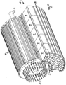
- the Figure 1 shows an electric drive system according to the invention with an electric motor 1 with an output shaft 2 and opposite rods 3 protruding from the stator for energizing the stator.
- the rods can preferably each be assigned to one or more phases, in particular with a phase voltage of less than 60 V.
- the outer lateral surface of the electric motor 1 has grooves 4, here with a dovetail profile, into which corresponding webs 5 on the inner lateral surface of the energy supply 6 shown here only in part can be inserted.
- the energy supply 6 is accommodated in a hollow cylindrical housing, which is divided here both in the axial direction and in the circumferential direction.
- the entire hollow cylindrical housing is formed into a plurality of ring segments 7, of which only those are shown here which lie axially one behind the other at a common circumferential position.
- This common circumferential position here extends over an angular range of 90 degrees, since there is a division in the circumferential direction into 4 segments.
- Heat pipes can be arranged in the grooves 9 in order to transfer heat generated at the end in power electronics (not shown here) and the heat of the motor 1 to the side of the output shaft 2.
- the ring segments 7 can also have grooves 10 on the outside, in which heat pipes can lie for heat transport.
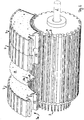
- the Figure 2 shows a view that clarifies that connecting boards 11 (in particular at least one) can be provided between two adjacent segments 7, in particular between each pair of two adjacent segments 7, which are axially one behind the other at a common circumferential position, in order to connect the battery cells within each To make segment 7 and between the adjacent segments 7. For example, all battery cells contained in the segments can be connected in series.
- Each segment can have its own assigned board
- the connecting plate 11 which is designed in the form of an annular segment, has contacts 12 which can be connected to a plate, not shown here, which can be located in the recess region 13, which extends in the axial direction and at an end lying in the circumferential direction 7a of each segment and is thus also arranged between two successive segments in the circumferential direction.
- the circuit board, not shown, can take over the battery management of the battery cells here.
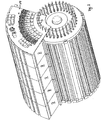
- Figure 3 shows the arrangement of a control board 14, which extends at least substantially over the same angular range as in the segment 7 and thus has the shape of a circular ring segment.
- the one shown here Control board 14 comprises power electronics for controlling those rods 3 of the stator which are in contact with the board 14 in the same angular range.
- the control board covers part of the end face of the motor 3 and essentially completely the end face of the last or first segment 7.
- three further identical functional units can be mounted on the motor 1, as a result of which the total electrical capacity can be quadrupled, as can the torque of the motor.
- four realized functional units form an energy supply in the sense of the invention, which extends in the circumferential direction over a full 360 degrees, in particular in this case additionally forms a fourfold redundancy.
- the invention is not limited to the 4-fold segmentation shown here. Both more and fewer segments can be provided.
Landscapes
- Engineering & Computer Science (AREA)
- Power Engineering (AREA)
- Chemical & Material Sciences (AREA)
- Chemical Kinetics & Catalysis (AREA)
- Electrochemistry (AREA)
- General Chemical & Material Sciences (AREA)
- Manufacturing & Machinery (AREA)
- Mechanical Engineering (AREA)
- Transportation (AREA)
- Microelectronics & Electronic Packaging (AREA)
- Life Sciences & Earth Sciences (AREA)
- Sustainable Development (AREA)
- Sustainable Energy (AREA)
- Combustion & Propulsion (AREA)
- Aviation & Aerospace Engineering (AREA)
- Electric Propulsion And Braking For Vehicles (AREA)
- Arrangement Or Mounting Of Propulsion Units For Vehicles (AREA)
- Motor Or Generator Frames (AREA)
Applications Claiming Priority (2)
| Application Number | Priority Date | Filing Date | Title |
|---|---|---|---|
| DE102015013403.5A DE102015013403A1 (de) | 2015-10-19 | 2015-10-19 | Elektro-Antriebssystem |
| PCT/EP2016/001688 WO2017067644A1 (de) | 2015-10-19 | 2016-10-12 | Elektro-antriebssystem |
Publications (2)
| Publication Number | Publication Date |
|---|---|
| EP3365961A1 EP3365961A1 (de) | 2018-08-29 |
| EP3365961B1 true EP3365961B1 (de) | 2020-06-03 |
Family
ID=57233374
Family Applications (1)
| Application Number | Title | Priority Date | Filing Date |
|---|---|---|---|
| EP16790873.0A Active EP3365961B1 (de) | 2015-10-19 | 2016-10-12 | Elektro-antriebssystem |
Country Status (7)
| Country | Link |
|---|---|
| US (1) | US10666116B2 (ja) |
| EP (1) | EP3365961B1 (ja) |
| JP (1) | JP6788909B2 (ja) |
| KR (1) | KR102606054B1 (ja) |
| CN (1) | CN108323223B (ja) |
| DE (1) | DE102015013403A1 (ja) |
| WO (1) | WO2017067644A1 (ja) |
Families Citing this family (6)
| Publication number | Priority date | Publication date | Assignee | Title |
|---|---|---|---|---|
| DE102015013403A1 (de) * | 2015-10-19 | 2017-04-20 | Bergische Universität Wuppertal | Elektro-Antriebssystem |
| DE102015014509A1 (de) * | 2015-11-11 | 2017-05-11 | Bergische Universität Wuppertal | Elektro-Antriebssystem |
| TWI656043B (zh) * | 2017-11-08 | 2019-04-11 | 財團法人工業技術研究院 | 電動輪 |
| DE102018103709A1 (de) * | 2018-02-20 | 2019-08-22 | stoba e-Systems GmbH | Antriebsstrang mit zwei unterschiedlich Spannung abgebenden Batterien, Elektro-Antriebs-System mit Niedervoltstäbe umgebende Hochvolt-Wicklungen, Elektromotor mit separatem Hochvolt-Pulswechselrichter und Verfahren zum Betreiben eines Elektromotors |
| JP7263943B2 (ja) * | 2019-06-27 | 2023-04-25 | 株式会社豊田中央研究所 | 円筒型電源システム |
| EP4246783A1 (de) * | 2022-03-18 | 2023-09-20 | Siemens Aktiengesellschaft | Elektromotor |
Citations (2)
| Publication number | Priority date | Publication date | Assignee | Title |
|---|---|---|---|---|
| US20050184689A1 (en) * | 2003-02-06 | 2005-08-25 | Wavecrest Laboratories | Adaptive electric motors and generators providing improved performance and efficiency |
| US20120168239A1 (en) * | 2009-06-24 | 2012-07-05 | Gardes Florian | Self-contained drive system |
Family Cites Families (28)
| Publication number | Priority date | Publication date | Assignee | Title |
|---|---|---|---|---|
| JPS5534980B2 (ja) * | 1974-07-02 | 1980-09-10 | ||
| US4749933A (en) * | 1986-02-26 | 1988-06-07 | Ben Aaron Max | Polyphase induction motor system and operating method |
| JP2525661Y2 (ja) * | 1991-12-03 | 1997-02-12 | マブチモーター株式会社 | 玩具用モータの接点構造 |
| US5227263A (en) * | 1992-05-22 | 1993-07-13 | The United States Of America As Represented By The Secretary Of The Navy | Reconfigurable heavy duty battery holder |
| US20030228516A1 (en) * | 2002-06-07 | 2003-12-11 | Mcdermott Patrick P. | Comformable battery |
| US6914357B2 (en) * | 2002-06-10 | 2005-07-05 | Visteon Global Technologies, Inc. | Electric machine with integrated power electronics |
| JP3559909B2 (ja) * | 2002-11-07 | 2004-09-02 | 日産自動車株式会社 | 機電一体型駆動装置 |
| JP4826214B2 (ja) * | 2005-11-04 | 2011-11-30 | 日産自動車株式会社 | 駆動システム |
| US20070141435A1 (en) | 2005-12-20 | 2007-06-21 | Hasz Wayne C | Fuel cell with a brazed interconnect and method of assembling the same |
| JP2007174757A (ja) * | 2005-12-20 | 2007-07-05 | Nissan Motor Co Ltd | ステータ回転可能型回転電機 |
| JP4987495B2 (ja) * | 2007-01-25 | 2012-07-25 | 株式会社東芝 | 鉄道車両駆動用モータドライブシステム |
| CN101428674A (zh) * | 2007-11-07 | 2009-05-13 | 王�华 | 动力轮 |
| KR100991220B1 (ko) | 2008-07-21 | 2010-11-04 | 삼성전자주식회사 | 접착된 계면을 갖는 기판 내의 콘택 구조체, 이를 구비하는반도체 소자 및 이를 제조하는 방법들 |
| JP5327646B2 (ja) * | 2009-06-24 | 2013-10-30 | 株式会社デンソー | 電子回路内蔵型モータ |
| US9027681B2 (en) * | 2009-12-04 | 2015-05-12 | Massachusetts Institute Of Technology | Hybrid sensor-enabled electric wheel and associated systems, multi-hub wheel spoking systems, and methods of manufacturing and installing wheel spokes |
| CN102110795B (zh) * | 2009-12-24 | 2015-03-04 | 三洋电机株式会社 | 电池组 |
| JP5490516B2 (ja) * | 2009-12-24 | 2014-05-14 | 三洋電機株式会社 | 電池パック |
| CN102544848B (zh) | 2010-12-30 | 2014-07-23 | 伊姆西公司 | 用于插座的壳体系统 |
| EP2479099A1 (en) * | 2011-01-24 | 2012-07-25 | Lin Hsiang Huang | Power output device for vehicle |
| AT511428B1 (de) * | 2011-04-21 | 2013-05-15 | Avl List Gmbh | Elektrische maschine |
| US10008910B2 (en) * | 2011-06-10 | 2018-06-26 | Axiflux Holdings Pty Ltd. | Electric motor/generator |
| GB201216099D0 (en) * | 2012-09-10 | 2012-10-24 | Protean Electric Ltd | Capacitor |
| DE102013100545B4 (de) * | 2013-01-18 | 2022-12-01 | Cayago Tec Gmbh | Wasserfahrzeug mit einer Akkumulatoreinheit |
| DE102013018720A1 (de) * | 2013-11-08 | 2015-05-13 | Man Truck & Bus Ag | Kurbelwellen-Startergenerator und Gehäuse für einen Kurbelwellen-Startergenerator |
| JP5862645B2 (ja) * | 2013-11-29 | 2016-02-16 | 株式会社デンソー | 駆動装置 |
| DE202014104276U1 (de) * | 2014-09-09 | 2014-09-19 | Ford Global Technologies, Llc | Antriebsrad mit Elektro-Radnabenmotor für Kraftfahrzeuge und Kraftfahrzeug |
| US10250104B2 (en) * | 2014-10-08 | 2019-04-02 | Borgwarner Inc. | Circuit layout for electric machine control electronics |
| DE102015013403A1 (de) * | 2015-10-19 | 2017-04-20 | Bergische Universität Wuppertal | Elektro-Antriebssystem |
-
2015
- 2015-10-19 DE DE102015013403.5A patent/DE102015013403A1/de not_active Withdrawn
-
2016
- 2016-10-12 JP JP2018521315A patent/JP6788909B2/ja active Active
- 2016-10-12 US US15/764,637 patent/US10666116B2/en active Active
- 2016-10-12 WO PCT/EP2016/001688 patent/WO2017067644A1/de active Application Filing
- 2016-10-12 KR KR1020187014078A patent/KR102606054B1/ko active IP Right Grant
- 2016-10-12 EP EP16790873.0A patent/EP3365961B1/de active Active
- 2016-10-12 CN CN201680061213.2A patent/CN108323223B/zh active Active
Patent Citations (2)
| Publication number | Priority date | Publication date | Assignee | Title |
|---|---|---|---|---|
| US20050184689A1 (en) * | 2003-02-06 | 2005-08-25 | Wavecrest Laboratories | Adaptive electric motors and generators providing improved performance and efficiency |
| US20120168239A1 (en) * | 2009-06-24 | 2012-07-05 | Gardes Florian | Self-contained drive system |
Also Published As
| Publication number | Publication date |
|---|---|
| US20180294694A1 (en) | 2018-10-11 |
| CN108323223B (zh) | 2021-03-23 |
| EP3365961A1 (de) | 2018-08-29 |
| JP2018534903A (ja) | 2018-11-22 |
| WO2017067644A1 (de) | 2017-04-27 |
| DE102015013403A1 (de) | 2017-04-20 |
| KR20180072748A (ko) | 2018-06-29 |
| KR102606054B1 (ko) | 2023-11-23 |
| JP6788909B2 (ja) | 2020-11-25 |
| US10666116B2 (en) | 2020-05-26 |
| CN108323223A (zh) | 2018-07-24 |
Similar Documents
| Publication | Publication Date | Title |
|---|---|---|
| EP3365961B1 (de) | Elektro-antriebssystem | |
| EP3375076B1 (de) | Elektro-antriebssystem | |
| DE112017001202T5 (de) | Elektrische Antriebsvorrichtung und elektrische Servolenkvorrichtung | |
| DE102016204445A1 (de) | Rotierende elektrische Maschine des Axialspalttyps | |
| DE112017001191T5 (de) | Elektrische Antriebsvorrichtung und elektrische Servolenkvorrichtung | |
| DE202012013152U1 (de) | Statorvorrichtung für einen Linearmotor und lineares Transportsystem | |
| DE102011052409A1 (de) | Motor und elektrische Servolenkung, die diesen Motor verwendet | |
| WO2010149439A2 (de) | Vorrichtung zur versorgung eines elektrischen antriebes für ein kraftfahrzeug | |
| EP3342629B1 (de) | Technik zum veränderlichen verschalten eines traktionsenergiespeichersystems | |
| DE102017217298A1 (de) | Elektrische Antriebseinrichtung | |
| DE102021106897A1 (de) | Elektrische maschine mit haarnadelwicklungen | |
| AT521291B1 (de) | Synchronmotor | |
| DE102018201206A1 (de) | Modulare Anordnung eines Umrichters und Luftfahrzeug mit einer derartigen Anordnung | |
| EP3259789B1 (de) | Überwachen einer zustandsgrösse wenigstens einer batteriezelle einer batterie | |
| WO2015067456A1 (de) | Energiespeichersystem für ein elektrisch angetriebenes fahrzeug | |
| DE102020113555A1 (de) | Stator für eine elektrische Mehrphasen- Synchron- oder Asynchronmaschine, sowie elektrische Maschine | |
| DE102013222293A1 (de) | Batteriemodul | |
| EP3755572B1 (de) | Antriebsstrang mit zwei unterschiedlich spannung abgebenden batterien, elektro-antriebs-system mit niedervoltstäbe umgebende hochvolt-wicklungen, elektromotor mit separatem hochvolt-pulswechselrichter und verfahren zum betreiben eines elektromotors | |
| DE102011006518A1 (de) | Spannungsversorgungseinheit | |
| DE102013215704A1 (de) | Batteriesystem mit einer Batterie-Trenneinheit und einer Batterie-Steuereinheit | |
| EP4323777A1 (de) | Phasenanschluss für elektromotoren zur phasenstrommessung | |
| WO2020249557A1 (de) | Motordrehrichtungserkennung bei einphasigen umrichtern | |
| DE102008050017A1 (de) | Doppelumrichter zur Ansteuerung einer ersten und einer zweiten elektrischen Maschine |
Legal Events
| Date | Code | Title | Description |
|---|---|---|---|
| STAA | Information on the status of an ep patent application or granted ep patent |
Free format text: STATUS: UNKNOWN |
|
| STAA | Information on the status of an ep patent application or granted ep patent |
Free format text: STATUS: THE INTERNATIONAL PUBLICATION HAS BEEN MADE |
|
| PUAI | Public reference made under article 153(3) epc to a published international application that has entered the european phase |
Free format text: ORIGINAL CODE: 0009012 |
|
| STAA | Information on the status of an ep patent application or granted ep patent |
Free format text: STATUS: REQUEST FOR EXAMINATION WAS MADE |
|
| 17P | Request for examination filed |
Effective date: 20180518 |
|
| AK | Designated contracting states |
Kind code of ref document: A1 Designated state(s): AL AT BE BG CH CY CZ DE DK EE ES FI FR GB GR HR HU IE IS IT LI LT LU LV MC MK MT NL NO PL PT RO RS SE SI SK SM TR |
|
| AX | Request for extension of the european patent |
Extension state: BA ME |
|
| RIN1 | Information on inventor provided before grant (corrected) |
Inventor name: FINKE, MARIUS Inventor name: BUTZMANN, STEFAN |
|
| DAV | Request for validation of the european patent (deleted) | ||
| DAX | Request for extension of the european patent (deleted) | ||
| STAA | Information on the status of an ep patent application or granted ep patent |
Free format text: STATUS: EXAMINATION IS IN PROGRESS |
|
| 17Q | First examination report despatched |
Effective date: 20190326 |
|
| RIC1 | Information provided on ipc code assigned before grant |
Ipc: H02K 11/33 20160101ALI20191004BHEP Ipc: H02K 11/00 20160101AFI20191004BHEP Ipc: H01M 2/10 20060101ALI20191004BHEP Ipc: H02K 5/20 20060101ALI20191004BHEP Ipc: H02K 11/215 20160101ALI20191004BHEP Ipc: B60K 1/04 20190101ALI20191004BHEP |
|
| GRAP | Despatch of communication of intention to grant a patent |
Free format text: ORIGINAL CODE: EPIDOSNIGR1 |
|
| STAA | Information on the status of an ep patent application or granted ep patent |
Free format text: STATUS: GRANT OF PATENT IS INTENDED |
|
| INTG | Intention to grant announced |
Effective date: 20200103 |
|
| GRAS | Grant fee paid |
Free format text: ORIGINAL CODE: EPIDOSNIGR3 |
|
| GRAA | (expected) grant |
Free format text: ORIGINAL CODE: 0009210 |
|
| STAA | Information on the status of an ep patent application or granted ep patent |
Free format text: STATUS: THE PATENT HAS BEEN GRANTED |
|
| AK | Designated contracting states |
Kind code of ref document: B1 Designated state(s): AL AT BE BG CH CY CZ DE DK EE ES FI FR GB GR HR HU IE IS IT LI LT LU LV MC MK MT NL NO PL PT RO RS SE SI SK SM TR |
|
| REG | Reference to a national code |
Ref country code: GB Ref legal event code: FG4D Free format text: NOT ENGLISH |
|
| REG | Reference to a national code |
Ref country code: CH Ref legal event code: EP Ref country code: AT Ref legal event code: REF Ref document number: 1278053 Country of ref document: AT Kind code of ref document: T Effective date: 20200615 |
|
| REG | Reference to a national code |
Ref country code: DE Ref legal event code: R096 Ref document number: 502016010144 Country of ref document: DE |
|
| REG | Reference to a national code |
Ref country code: LT Ref legal event code: MG4D |
|
| PG25 | Lapsed in a contracting state [announced via postgrant information from national office to epo] |
Ref country code: SE Free format text: LAPSE BECAUSE OF FAILURE TO SUBMIT A TRANSLATION OF THE DESCRIPTION OR TO PAY THE FEE WITHIN THE PRESCRIBED TIME-LIMIT Effective date: 20200603 Ref country code: FI Free format text: LAPSE BECAUSE OF FAILURE TO SUBMIT A TRANSLATION OF THE DESCRIPTION OR TO PAY THE FEE WITHIN THE PRESCRIBED TIME-LIMIT Effective date: 20200603 Ref country code: NO Free format text: LAPSE BECAUSE OF FAILURE TO SUBMIT A TRANSLATION OF THE DESCRIPTION OR TO PAY THE FEE WITHIN THE PRESCRIBED TIME-LIMIT Effective date: 20200903 Ref country code: GR Free format text: LAPSE BECAUSE OF FAILURE TO SUBMIT A TRANSLATION OF THE DESCRIPTION OR TO PAY THE FEE WITHIN THE PRESCRIBED TIME-LIMIT Effective date: 20200904 Ref country code: LT Free format text: LAPSE BECAUSE OF FAILURE TO SUBMIT A TRANSLATION OF THE DESCRIPTION OR TO PAY THE FEE WITHIN THE PRESCRIBED TIME-LIMIT Effective date: 20200603 |
|
| REG | Reference to a national code |
Ref country code: NL Ref legal event code: MP Effective date: 20200603 |
|
| PG25 | Lapsed in a contracting state [announced via postgrant information from national office to epo] |
Ref country code: LV Free format text: LAPSE BECAUSE OF FAILURE TO SUBMIT A TRANSLATION OF THE DESCRIPTION OR TO PAY THE FEE WITHIN THE PRESCRIBED TIME-LIMIT Effective date: 20200603 Ref country code: RS Free format text: LAPSE BECAUSE OF FAILURE TO SUBMIT A TRANSLATION OF THE DESCRIPTION OR TO PAY THE FEE WITHIN THE PRESCRIBED TIME-LIMIT Effective date: 20200603 Ref country code: BG Free format text: LAPSE BECAUSE OF FAILURE TO SUBMIT A TRANSLATION OF THE DESCRIPTION OR TO PAY THE FEE WITHIN THE PRESCRIBED TIME-LIMIT Effective date: 20200903 Ref country code: HR Free format text: LAPSE BECAUSE OF FAILURE TO SUBMIT A TRANSLATION OF THE DESCRIPTION OR TO PAY THE FEE WITHIN THE PRESCRIBED TIME-LIMIT Effective date: 20200603 |
|
| PG25 | Lapsed in a contracting state [announced via postgrant information from national office to epo] |
Ref country code: NL Free format text: LAPSE BECAUSE OF FAILURE TO SUBMIT A TRANSLATION OF THE DESCRIPTION OR TO PAY THE FEE WITHIN THE PRESCRIBED TIME-LIMIT Effective date: 20200603 Ref country code: AL Free format text: LAPSE BECAUSE OF FAILURE TO SUBMIT A TRANSLATION OF THE DESCRIPTION OR TO PAY THE FEE WITHIN THE PRESCRIBED TIME-LIMIT Effective date: 20200603 |
|
| PG25 | Lapsed in a contracting state [announced via postgrant information from national office to epo] |
Ref country code: RO Free format text: LAPSE BECAUSE OF FAILURE TO SUBMIT A TRANSLATION OF THE DESCRIPTION OR TO PAY THE FEE WITHIN THE PRESCRIBED TIME-LIMIT Effective date: 20200603 Ref country code: IT Free format text: LAPSE BECAUSE OF FAILURE TO SUBMIT A TRANSLATION OF THE DESCRIPTION OR TO PAY THE FEE WITHIN THE PRESCRIBED TIME-LIMIT Effective date: 20200603 Ref country code: CZ Free format text: LAPSE BECAUSE OF FAILURE TO SUBMIT A TRANSLATION OF THE DESCRIPTION OR TO PAY THE FEE WITHIN THE PRESCRIBED TIME-LIMIT Effective date: 20200603 Ref country code: PT Free format text: LAPSE BECAUSE OF FAILURE TO SUBMIT A TRANSLATION OF THE DESCRIPTION OR TO PAY THE FEE WITHIN THE PRESCRIBED TIME-LIMIT Effective date: 20201006 Ref country code: EE Free format text: LAPSE BECAUSE OF FAILURE TO SUBMIT A TRANSLATION OF THE DESCRIPTION OR TO PAY THE FEE WITHIN THE PRESCRIBED TIME-LIMIT Effective date: 20200603 Ref country code: SM Free format text: LAPSE BECAUSE OF FAILURE TO SUBMIT A TRANSLATION OF THE DESCRIPTION OR TO PAY THE FEE WITHIN THE PRESCRIBED TIME-LIMIT Effective date: 20200603 Ref country code: ES Free format text: LAPSE BECAUSE OF FAILURE TO SUBMIT A TRANSLATION OF THE DESCRIPTION OR TO PAY THE FEE WITHIN THE PRESCRIBED TIME-LIMIT Effective date: 20200603 |
|
| PG25 | Lapsed in a contracting state [announced via postgrant information from national office to epo] |
Ref country code: SK Free format text: LAPSE BECAUSE OF FAILURE TO SUBMIT A TRANSLATION OF THE DESCRIPTION OR TO PAY THE FEE WITHIN THE PRESCRIBED TIME-LIMIT Effective date: 20200603 Ref country code: PL Free format text: LAPSE BECAUSE OF FAILURE TO SUBMIT A TRANSLATION OF THE DESCRIPTION OR TO PAY THE FEE WITHIN THE PRESCRIBED TIME-LIMIT Effective date: 20200603 Ref country code: IS Free format text: LAPSE BECAUSE OF FAILURE TO SUBMIT A TRANSLATION OF THE DESCRIPTION OR TO PAY THE FEE WITHIN THE PRESCRIBED TIME-LIMIT Effective date: 20201003 |
|
| REG | Reference to a national code |
Ref country code: DE Ref legal event code: R097 Ref document number: 502016010144 Country of ref document: DE |
|
| PLBE | No opposition filed within time limit |
Free format text: ORIGINAL CODE: 0009261 |
|
| STAA | Information on the status of an ep patent application or granted ep patent |
Free format text: STATUS: NO OPPOSITION FILED WITHIN TIME LIMIT |
|
| PG25 | Lapsed in a contracting state [announced via postgrant information from national office to epo] |
Ref country code: DK Free format text: LAPSE BECAUSE OF FAILURE TO SUBMIT A TRANSLATION OF THE DESCRIPTION OR TO PAY THE FEE WITHIN THE PRESCRIBED TIME-LIMIT Effective date: 20200603 |
|
| 26N | No opposition filed |
Effective date: 20210304 |
|
| PG25 | Lapsed in a contracting state [announced via postgrant information from national office to epo] |
Ref country code: SI Free format text: LAPSE BECAUSE OF FAILURE TO SUBMIT A TRANSLATION OF THE DESCRIPTION OR TO PAY THE FEE WITHIN THE PRESCRIBED TIME-LIMIT Effective date: 20200603 |
|
| REG | Reference to a national code |
Ref country code: CH Ref legal event code: PL |
|
| PG25 | Lapsed in a contracting state [announced via postgrant information from national office to epo] |
Ref country code: LU Free format text: LAPSE BECAUSE OF NON-PAYMENT OF DUE FEES Effective date: 20201012 Ref country code: MC Free format text: LAPSE BECAUSE OF FAILURE TO SUBMIT A TRANSLATION OF THE DESCRIPTION OR TO PAY THE FEE WITHIN THE PRESCRIBED TIME-LIMIT Effective date: 20200603 |
|
| REG | Reference to a national code |
Ref country code: BE Ref legal event code: MM Effective date: 20201031 |
|
| PG25 | Lapsed in a contracting state [announced via postgrant information from national office to epo] |
Ref country code: BE Free format text: LAPSE BECAUSE OF NON-PAYMENT OF DUE FEES Effective date: 20201031 Ref country code: CH Free format text: LAPSE BECAUSE OF NON-PAYMENT OF DUE FEES Effective date: 20201031 Ref country code: LI Free format text: LAPSE BECAUSE OF NON-PAYMENT OF DUE FEES Effective date: 20201031 |
|
| PG25 | Lapsed in a contracting state [announced via postgrant information from national office to epo] |
Ref country code: IE Free format text: LAPSE BECAUSE OF NON-PAYMENT OF DUE FEES Effective date: 20201012 |
|
| PG25 | Lapsed in a contracting state [announced via postgrant information from national office to epo] |
Ref country code: TR Free format text: LAPSE BECAUSE OF FAILURE TO SUBMIT A TRANSLATION OF THE DESCRIPTION OR TO PAY THE FEE WITHIN THE PRESCRIBED TIME-LIMIT Effective date: 20200603 Ref country code: MT Free format text: LAPSE BECAUSE OF FAILURE TO SUBMIT A TRANSLATION OF THE DESCRIPTION OR TO PAY THE FEE WITHIN THE PRESCRIBED TIME-LIMIT Effective date: 20200603 Ref country code: CY Free format text: LAPSE BECAUSE OF FAILURE TO SUBMIT A TRANSLATION OF THE DESCRIPTION OR TO PAY THE FEE WITHIN THE PRESCRIBED TIME-LIMIT Effective date: 20200603 |
|
| PG25 | Lapsed in a contracting state [announced via postgrant information from national office to epo] |
Ref country code: MK Free format text: LAPSE BECAUSE OF FAILURE TO SUBMIT A TRANSLATION OF THE DESCRIPTION OR TO PAY THE FEE WITHIN THE PRESCRIBED TIME-LIMIT Effective date: 20200603 |
|
| REG | Reference to a national code |
Ref country code: DE Ref legal event code: R082 Ref document number: 502016010144 Country of ref document: DE Representative=s name: WINTER, BRANDL - PARTNERSCHAFT MBB, PATENTANWA, DE |
|
| PGFP | Annual fee paid to national office [announced via postgrant information from national office to epo] |
Ref country code: GB Payment date: 20231025 Year of fee payment: 8 |
|
| PGFP | Annual fee paid to national office [announced via postgrant information from national office to epo] |
Ref country code: FR Payment date: 20231023 Year of fee payment: 8 Ref country code: DE Payment date: 20231016 Year of fee payment: 8 Ref country code: AT Payment date: 20231019 Year of fee payment: 8 |
|
| REG | Reference to a national code |
Ref country code: DE Ref legal event code: R081 Ref document number: 502016010144 Country of ref document: DE Owner name: STOBA E-SYSTEMS GMBH, DE Free format text: FORMER OWNER: BERGISCHE UNIVERSITAET WUPPERTAL, 42119 WUPPERTAL, DE |