EP3365961B1 - Electro drive system - Google Patents
Electro drive system Download PDFInfo
- Publication number
- EP3365961B1 EP3365961B1 EP16790873.0A EP16790873A EP3365961B1 EP 3365961 B1 EP3365961 B1 EP 3365961B1 EP 16790873 A EP16790873 A EP 16790873A EP 3365961 B1 EP3365961 B1 EP 3365961B1
- Authority
- EP
- European Patent Office
- Prior art keywords
- segments
- electric motor
- drive system
- electric drive
- circuit board
- Prior art date
- Legal status (The legal status is an assumption and is not a legal conclusion. Google has not performed a legal analysis and makes no representation as to the accuracy of the status listed.)
- Active
Links
- 238000004146 energy storage Methods 0.000 claims description 34
- 210000000352 storage cell Anatomy 0.000 claims description 26
- 210000004027 cell Anatomy 0.000 claims description 24
- 230000004323 axial length Effects 0.000 claims description 13
- 238000004804 winding Methods 0.000 claims description 3
- 238000003475 lamination Methods 0.000 claims 1
- 238000001816 cooling Methods 0.000 description 7
- 238000009413 insulation Methods 0.000 description 5
- 238000010276 construction Methods 0.000 description 3
- 230000001276 controlling effect Effects 0.000 description 3
- 238000013461 design Methods 0.000 description 3
- 238000011161 development Methods 0.000 description 2
- 230000018109 developmental process Effects 0.000 description 2
- 230000000694 effects Effects 0.000 description 2
- 238000009434 installation Methods 0.000 description 2
- 239000007788 liquid Substances 0.000 description 2
- 238000012423 maintenance Methods 0.000 description 2
- 238000012546 transfer Methods 0.000 description 2
- 241001136792 Alle Species 0.000 description 1
- WHXSMMKQMYFTQS-UHFFFAOYSA-N Lithium Chemical compound [Li] WHXSMMKQMYFTQS-UHFFFAOYSA-N 0.000 description 1
- 230000032683 aging Effects 0.000 description 1
- 230000000712 assembly Effects 0.000 description 1
- 238000000429 assembly Methods 0.000 description 1
- 230000015556 catabolic process Effects 0.000 description 1
- 239000004020 conductor Substances 0.000 description 1
- 230000008878 coupling Effects 0.000 description 1
- 238000010168 coupling process Methods 0.000 description 1
- 238000005859 coupling reaction Methods 0.000 description 1
- 230000007547 defect Effects 0.000 description 1
- 230000002950 deficient Effects 0.000 description 1
- 238000006731 degradation reaction Methods 0.000 description 1
- 238000001514 detection method Methods 0.000 description 1
- 238000003745 diagnosis Methods 0.000 description 1
- 238000005538 encapsulation Methods 0.000 description 1
- 238000011156 evaluation Methods 0.000 description 1
- 238000011990 functional testing Methods 0.000 description 1
- 230000001939 inductive effect Effects 0.000 description 1
- 239000011810 insulating material Substances 0.000 description 1
- 239000012212 insulator Substances 0.000 description 1
- 230000010354 integration Effects 0.000 description 1
- 229910052744 lithium Inorganic materials 0.000 description 1
- 238000005259 measurement Methods 0.000 description 1
- 229910052751 metal Inorganic materials 0.000 description 1
- 239000002184 metal Substances 0.000 description 1
- 238000000034 method Methods 0.000 description 1
- 238000012544 monitoring process Methods 0.000 description 1
- 229920000642 polymer Polymers 0.000 description 1
- 230000001105 regulatory effect Effects 0.000 description 1
- 230000011218 segmentation Effects 0.000 description 1
- 230000003068 static effect Effects 0.000 description 1
- 230000001360 synchronised effect Effects 0.000 description 1
Images
Classifications
-
- H—ELECTRICITY
- H02—GENERATION; CONVERSION OR DISTRIBUTION OF ELECTRIC POWER
- H02K—DYNAMO-ELECTRIC MACHINES
- H02K11/00—Structural association of dynamo-electric machines with electric components or with devices for shielding, monitoring or protection
- H02K11/0094—Structural association with other electrical or electronic devices
-
- B—PERFORMING OPERATIONS; TRANSPORTING
- B60—VEHICLES IN GENERAL
- B60K—ARRANGEMENT OR MOUNTING OF PROPULSION UNITS OR OF TRANSMISSIONS IN VEHICLES; ARRANGEMENT OR MOUNTING OF PLURAL DIVERSE PRIME-MOVERS IN VEHICLES; AUXILIARY DRIVES FOR VEHICLES; INSTRUMENTATION OR DASHBOARDS FOR VEHICLES; ARRANGEMENTS IN CONNECTION WITH COOLING, AIR INTAKE, GAS EXHAUST OR FUEL SUPPLY OF PROPULSION UNITS IN VEHICLES
- B60K1/00—Arrangement or mounting of electrical propulsion units
- B60K1/04—Arrangement or mounting of electrical propulsion units of the electric storage means for propulsion
-
- B—PERFORMING OPERATIONS; TRANSPORTING
- B60—VEHICLES IN GENERAL
- B60L—PROPULSION OF ELECTRICALLY-PROPELLED VEHICLES; SUPPLYING ELECTRIC POWER FOR AUXILIARY EQUIPMENT OF ELECTRICALLY-PROPELLED VEHICLES; ELECTRODYNAMIC BRAKE SYSTEMS FOR VEHICLES IN GENERAL; MAGNETIC SUSPENSION OR LEVITATION FOR VEHICLES; MONITORING OPERATING VARIABLES OF ELECTRICALLY-PROPELLED VEHICLES; ELECTRIC SAFETY DEVICES FOR ELECTRICALLY-PROPELLED VEHICLES
- B60L50/00—Electric propulsion with power supplied within the vehicle
- B60L50/50—Electric propulsion with power supplied within the vehicle using propulsion power supplied by batteries or fuel cells
- B60L50/60—Electric propulsion with power supplied within the vehicle using propulsion power supplied by batteries or fuel cells using power supplied by batteries
- B60L50/64—Constructional details of batteries specially adapted for electric vehicles
-
- B—PERFORMING OPERATIONS; TRANSPORTING
- B60—VEHICLES IN GENERAL
- B60L—PROPULSION OF ELECTRICALLY-PROPELLED VEHICLES; SUPPLYING ELECTRIC POWER FOR AUXILIARY EQUIPMENT OF ELECTRICALLY-PROPELLED VEHICLES; ELECTRODYNAMIC BRAKE SYSTEMS FOR VEHICLES IN GENERAL; MAGNETIC SUSPENSION OR LEVITATION FOR VEHICLES; MONITORING OPERATING VARIABLES OF ELECTRICALLY-PROPELLED VEHICLES; ELECTRIC SAFETY DEVICES FOR ELECTRICALLY-PROPELLED VEHICLES
- B60L50/00—Electric propulsion with power supplied within the vehicle
- B60L50/50—Electric propulsion with power supplied within the vehicle using propulsion power supplied by batteries or fuel cells
- B60L50/60—Electric propulsion with power supplied within the vehicle using propulsion power supplied by batteries or fuel cells using power supplied by batteries
- B60L50/66—Arrangements of batteries
-
- H—ELECTRICITY
- H01—ELECTRIC ELEMENTS
- H01M—PROCESSES OR MEANS, e.g. BATTERIES, FOR THE DIRECT CONVERSION OF CHEMICAL ENERGY INTO ELECTRICAL ENERGY
- H01M10/00—Secondary cells; Manufacture thereof
- H01M10/60—Heating or cooling; Temperature control
- H01M10/61—Types of temperature control
- H01M10/613—Cooling or keeping cold
-
- H—ELECTRICITY
- H01—ELECTRIC ELEMENTS
- H01M—PROCESSES OR MEANS, e.g. BATTERIES, FOR THE DIRECT CONVERSION OF CHEMICAL ENERGY INTO ELECTRICAL ENERGY
- H01M10/00—Secondary cells; Manufacture thereof
- H01M10/60—Heating or cooling; Temperature control
- H01M10/62—Heating or cooling; Temperature control specially adapted for specific applications
- H01M10/625—Vehicles
-
- H—ELECTRICITY
- H01—ELECTRIC ELEMENTS
- H01M—PROCESSES OR MEANS, e.g. BATTERIES, FOR THE DIRECT CONVERSION OF CHEMICAL ENERGY INTO ELECTRICAL ENERGY
- H01M10/00—Secondary cells; Manufacture thereof
- H01M10/60—Heating or cooling; Temperature control
- H01M10/64—Heating or cooling; Temperature control characterised by the shape of the cells
- H01M10/643—Cylindrical cells
-
- H—ELECTRICITY
- H01—ELECTRIC ELEMENTS
- H01M—PROCESSES OR MEANS, e.g. BATTERIES, FOR THE DIRECT CONVERSION OF CHEMICAL ENERGY INTO ELECTRICAL ENERGY
- H01M10/00—Secondary cells; Manufacture thereof
- H01M10/60—Heating or cooling; Temperature control
- H01M10/65—Means for temperature control structurally associated with the cells
- H01M10/655—Solid structures for heat exchange or heat conduction
- H01M10/6556—Solid parts with flow channel passages or pipes for heat exchange
-
- H—ELECTRICITY
- H01—ELECTRIC ELEMENTS
- H01M—PROCESSES OR MEANS, e.g. BATTERIES, FOR THE DIRECT CONVERSION OF CHEMICAL ENERGY INTO ELECTRICAL ENERGY
- H01M10/00—Secondary cells; Manufacture thereof
- H01M10/60—Heating or cooling; Temperature control
- H01M10/65—Means for temperature control structurally associated with the cells
- H01M10/658—Means for temperature control structurally associated with the cells by thermal insulation or shielding
-
- H—ELECTRICITY
- H01—ELECTRIC ELEMENTS
- H01M—PROCESSES OR MEANS, e.g. BATTERIES, FOR THE DIRECT CONVERSION OF CHEMICAL ENERGY INTO ELECTRICAL ENERGY
- H01M50/00—Constructional details or processes of manufacture of the non-active parts of electrochemical cells other than fuel cells, e.g. hybrid cells
- H01M50/20—Mountings; Secondary casings or frames; Racks, modules or packs; Suspension devices; Shock absorbers; Transport or carrying devices; Holders
- H01M50/204—Racks, modules or packs for multiple batteries or multiple cells
- H01M50/207—Racks, modules or packs for multiple batteries or multiple cells characterised by their shape
- H01M50/213—Racks, modules or packs for multiple batteries or multiple cells characterised by their shape adapted for cells having curved cross-section, e.g. round or elliptic
-
- H—ELECTRICITY
- H01—ELECTRIC ELEMENTS
- H01M—PROCESSES OR MEANS, e.g. BATTERIES, FOR THE DIRECT CONVERSION OF CHEMICAL ENERGY INTO ELECTRICAL ENERGY
- H01M50/00—Constructional details or processes of manufacture of the non-active parts of electrochemical cells other than fuel cells, e.g. hybrid cells
- H01M50/20—Mountings; Secondary casings or frames; Racks, modules or packs; Suspension devices; Shock absorbers; Transport or carrying devices; Holders
- H01M50/233—Mountings; Secondary casings or frames; Racks, modules or packs; Suspension devices; Shock absorbers; Transport or carrying devices; Holders characterised by physical properties of casings or racks, e.g. dimensions
- H01M50/24—Mountings; Secondary casings or frames; Racks, modules or packs; Suspension devices; Shock absorbers; Transport or carrying devices; Holders characterised by physical properties of casings or racks, e.g. dimensions adapted for protecting batteries from their environment, e.g. from corrosion
-
- H—ELECTRICITY
- H01—ELECTRIC ELEMENTS
- H01M—PROCESSES OR MEANS, e.g. BATTERIES, FOR THE DIRECT CONVERSION OF CHEMICAL ENERGY INTO ELECTRICAL ENERGY
- H01M50/00—Constructional details or processes of manufacture of the non-active parts of electrochemical cells other than fuel cells, e.g. hybrid cells
- H01M50/20—Mountings; Secondary casings or frames; Racks, modules or packs; Suspension devices; Shock absorbers; Transport or carrying devices; Holders
- H01M50/249—Mountings; Secondary casings or frames; Racks, modules or packs; Suspension devices; Shock absorbers; Transport or carrying devices; Holders specially adapted for aircraft or vehicles, e.g. cars or trains
-
- H—ELECTRICITY
- H02—GENERATION; CONVERSION OR DISTRIBUTION OF ELECTRIC POWER
- H02K—DYNAMO-ELECTRIC MACHINES
- H02K11/00—Structural association of dynamo-electric machines with electric components or with devices for shielding, monitoring or protection
- H02K11/20—Structural association of dynamo-electric machines with electric components or with devices for shielding, monitoring or protection for measuring, monitoring, testing, protecting or switching
- H02K11/21—Devices for sensing speed or position, or actuated thereby
- H02K11/215—Magnetic effect devices, e.g. Hall-effect or magneto-resistive elements
-
- H—ELECTRICITY
- H02—GENERATION; CONVERSION OR DISTRIBUTION OF ELECTRIC POWER
- H02K—DYNAMO-ELECTRIC MACHINES
- H02K11/00—Structural association of dynamo-electric machines with electric components or with devices for shielding, monitoring or protection
- H02K11/30—Structural association with control circuits or drive circuits
- H02K11/33—Drive circuits, e.g. power electronics
-
- H—ELECTRICITY
- H02—GENERATION; CONVERSION OR DISTRIBUTION OF ELECTRIC POWER
- H02K—DYNAMO-ELECTRIC MACHINES
- H02K5/00—Casings; Enclosures; Supports
- H02K5/04—Casings or enclosures characterised by the shape, form or construction thereof
-
- H—ELECTRICITY
- H02—GENERATION; CONVERSION OR DISTRIBUTION OF ELECTRIC POWER
- H02K—DYNAMO-ELECTRIC MACHINES
- H02K5/00—Casings; Enclosures; Supports
- H02K5/04—Casings or enclosures characterised by the shape, form or construction thereof
- H02K5/20—Casings or enclosures characterised by the shape, form or construction thereof with channels or ducts for flow of cooling medium
- H02K5/203—Casings or enclosures characterised by the shape, form or construction thereof with channels or ducts for flow of cooling medium specially adapted for liquids, e.g. cooling jackets
-
- H—ELECTRICITY
- H02—GENERATION; CONVERSION OR DISTRIBUTION OF ELECTRIC POWER
- H02K—DYNAMO-ELECTRIC MACHINES
- H02K9/00—Arrangements for cooling or ventilating
-
- H—ELECTRICITY
- H02—GENERATION; CONVERSION OR DISTRIBUTION OF ELECTRIC POWER
- H02K—DYNAMO-ELECTRIC MACHINES
- H02K9/00—Arrangements for cooling or ventilating
- H02K9/22—Arrangements for cooling or ventilating by solid heat conducting material embedded in, or arranged in contact with, the stator or rotor, e.g. heat bridges
- H02K9/225—Heat pipes
-
- H—ELECTRICITY
- H01—ELECTRIC ELEMENTS
- H01M—PROCESSES OR MEANS, e.g. BATTERIES, FOR THE DIRECT CONVERSION OF CHEMICAL ENERGY INTO ELECTRICAL ENERGY
- H01M2220/00—Batteries for particular applications
- H01M2220/20—Batteries in motive systems, e.g. vehicle, ship, plane
-
- H—ELECTRICITY
- H02—GENERATION; CONVERSION OR DISTRIBUTION OF ELECTRIC POWER
- H02K—DYNAMO-ELECTRIC MACHINES
- H02K2213/00—Specific aspects, not otherwise provided for and not covered by codes H02K2201/00 - H02K2211/00
- H02K2213/12—Machines characterised by the modularity of some components
-
- Y—GENERAL TAGGING OF NEW TECHNOLOGICAL DEVELOPMENTS; GENERAL TAGGING OF CROSS-SECTIONAL TECHNOLOGIES SPANNING OVER SEVERAL SECTIONS OF THE IPC; TECHNICAL SUBJECTS COVERED BY FORMER USPC CROSS-REFERENCE ART COLLECTIONS [XRACs] AND DIGESTS
- Y02—TECHNOLOGIES OR APPLICATIONS FOR MITIGATION OR ADAPTATION AGAINST CLIMATE CHANGE
- Y02E—REDUCTION OF GREENHOUSE GAS [GHG] EMISSIONS, RELATED TO ENERGY GENERATION, TRANSMISSION OR DISTRIBUTION
- Y02E60/00—Enabling technologies; Technologies with a potential or indirect contribution to GHG emissions mitigation
- Y02E60/10—Energy storage using batteries
-
- Y—GENERAL TAGGING OF NEW TECHNOLOGICAL DEVELOPMENTS; GENERAL TAGGING OF CROSS-SECTIONAL TECHNOLOGIES SPANNING OVER SEVERAL SECTIONS OF THE IPC; TECHNICAL SUBJECTS COVERED BY FORMER USPC CROSS-REFERENCE ART COLLECTIONS [XRACs] AND DIGESTS
- Y02—TECHNOLOGIES OR APPLICATIONS FOR MITIGATION OR ADAPTATION AGAINST CLIMATE CHANGE
- Y02P—CLIMATE CHANGE MITIGATION TECHNOLOGIES IN THE PRODUCTION OR PROCESSING OF GOODS
- Y02P70/00—Climate change mitigation technologies in the production process for final industrial or consumer products
- Y02P70/50—Manufacturing or production processes characterised by the final manufactured product
-
- Y—GENERAL TAGGING OF NEW TECHNOLOGICAL DEVELOPMENTS; GENERAL TAGGING OF CROSS-SECTIONAL TECHNOLOGIES SPANNING OVER SEVERAL SECTIONS OF THE IPC; TECHNICAL SUBJECTS COVERED BY FORMER USPC CROSS-REFERENCE ART COLLECTIONS [XRACs] AND DIGESTS
- Y02—TECHNOLOGIES OR APPLICATIONS FOR MITIGATION OR ADAPTATION AGAINST CLIMATE CHANGE
- Y02T—CLIMATE CHANGE MITIGATION TECHNOLOGIES RELATED TO TRANSPORTATION
- Y02T10/00—Road transport of goods or passengers
- Y02T10/60—Other road transportation technologies with climate change mitigation effect
- Y02T10/64—Electric machine technologies in electromobility
-
- Y—GENERAL TAGGING OF NEW TECHNOLOGICAL DEVELOPMENTS; GENERAL TAGGING OF CROSS-SECTIONAL TECHNOLOGIES SPANNING OVER SEVERAL SECTIONS OF THE IPC; TECHNICAL SUBJECTS COVERED BY FORMER USPC CROSS-REFERENCE ART COLLECTIONS [XRACs] AND DIGESTS
- Y02—TECHNOLOGIES OR APPLICATIONS FOR MITIGATION OR ADAPTATION AGAINST CLIMATE CHANGE
- Y02T—CLIMATE CHANGE MITIGATION TECHNOLOGIES RELATED TO TRANSPORTATION
- Y02T10/00—Road transport of goods or passengers
- Y02T10/60—Other road transportation technologies with climate change mitigation effect
- Y02T10/70—Energy storage systems for electromobility, e.g. batteries
Definitions
- the invention relates to an electric drive system, in particular for vehicles, comprising an electric motor and a power supply, in particular including a pulse-controlled inverter and power electronics, the power supply being arranged radially on the outside of the electric motor and in the circumferential direction around the electric motor.
- Today's drive systems of this type usually include energy storage cells, such as batteries, in the field of energy supply, which are understood to mean in particular those of the rechargeable type, such as Lithium polymer batteries.
- energy storage cells such as batteries
- the rechargeable type such as Lithium polymer batteries.
- pulse inverters are regularly provided in such a drive system.
- the energy storage cells have the task of providing the energy required for operating the drive system, in particular driving a vehicle, or of storing it during charging.
- the pulse inverter converts the DC voltage provided by the battery into a customary one three-phase AC voltage, with which an electric motor, for example a synchronous or asynchronous machine, is then operated via power electronics, which takes over the control of the stator windings.
- the energy storage cells, pulse inverters and power electronics are usually manufactured independently of one another and form independent units that are connected to one another via cable harnesses.
- the energy storage cells, pulse inverters and power electronics are usually manufactured independently of one another and form independent units that are connected to one another via cable harnesses.
- the battery could either be designed with a DC voltage of 100V and an output current of approx. 1000A or with higher voltages and correspondingly lower currents.
- the voltage level of typically> 400V continues to result in the current state of the art in considerable requirements with regard to the electrical safety of such systems and entails considerable effort with regard to the insulation of the individual components from the vehicle chassis and the corresponding insulation monitoring.
- An essential criterion when designing an electric or hybrid drive for vehicles is the volumetric energy or power density, i.e. the volume of the electric drive train based on the energy content (which is a measure of the range of the vehicle) or based on the weight of the drive train.
- the extension of the energy supply or a housing receiving it does not necessarily have to be over the full circumferential angle of 360 degrees, but is preferably provided so that in this case an electric motor is completely surrounded by the energy supply.
- the essential idea of the invention is to bring the energy supply locally as close as possible to the electric motor. Due to the arrangement radially on the outside of the electric motor, in particular on its outer casing surface, which - apart from a possible surface contouring / structuring - is regularly cylindrical, there is still the need, apart from internal current paths, for the energy from the energy supply via the axial length of the electric motor and, if necessary, the radial spacing between the stator connections and the power supply. The paths to be bridged are clearly reduced compared to the prior art.
- the invention provides for the energy supply, in particular the energy storage cells (battery cells) required for this, to be in a hollow cylindrical one Arrange housing, in the inner hollow area of which the electric motor is arranged.
- the cylinder axis of the energy supply or of its housing and the motor axis are preferably collinear.
- the arrangement is further preferred such that the axial length of the energy supply, or of its housing, is at least substantially equal to the axial length of the motor housing, possibly up to 150% of its length.
- the arrangement according to the invention creates a manageable unit, which is defined by the external dimensions of the energy supply and completely includes the electric motor therein, in particular also the entire electronics for controlling the electric motor and for the energy management of the energy storage cells.
- the invention can provide that the hollow cylindrical housing has a plurality of recesses, in which energy storage cells are accommodated or at least can be accommodated. These recesses, in particular also further assemblies required for operation, are preferably arranged completely between the inner wall and outer wall of the hollow cylindrical housing.
- the recesses can be provided to design the recesses in a cylindrical manner, so that battery cells with standard sizes, which are common on the market, can be accommodated therein, for example those as are known from laptop batteries.
- the recesses are preferably oriented so that they extend in the axial direction.
- the battery cells can preferably in both possible, 180 degrees differing installation positions can be arranged, which simplifies the desired electrical connection.
- the invention further provides that the hollow cylindrical housing is subdivided to form subunits. On the one hand, this results in greater ease of maintenance and cost reduction, e.g. if defective parts have to be replaced.
- the invention provides for the hollow cylindrical housing of the energy supply to be divided into a plurality of ring elements in the axial direction, each ring element being divided into at least two segments in the circumferential direction.
- the axial length of each ring element can be adapted to receive exactly one axially lying energy storage cell (battery cell) in a respective cylindrical recess.
- the axial length of a ring element can e.g. be exactly the same or (somewhat) smaller than the axial length of an energy storage cell.
- the axial length can be adapted to a multiple (at least twice) the axial length of an energy storage cell.
- Each such ring element can form a self-contained energy storage module, in particular with which alone the operation of the electric motor can be possible.
- the invention provides that the hollow cylindrical housing is divided into at least two segments in the circumferential direction. Each segment can have an angular extent of 360 ° / number of segments. Each such segment, which extends over the entire axial length of the hollow cylindrical housing, can form a self-contained energy storage module, in particular with which the operation of the electric motor alone can be possible.
- each aforementioned ring element is divided into at least two segments in the circumferential direction.
- Each (ring element) segment can in turn have an angular extent of 360 ° / number of segments.
- the total number of all segments lying behind one another in the axial direction at a common circumferential position, in particular by means of electrical interconnection forms an energy storage module with which the operation of the electric motor alone is already possible. This results in a number of energy storage modules which corresponds to the number of segments (per ring element).
- the housing of the energy supply thus has a total of a number of subunits, which corresponds to the number of ring elements multiplied by the number of segments per ring element.
- a corresponding variety of possible electrical interconnections can be implemented in this way.
- At least one connecting plate is arranged between two adjacent axially successive segments of ring elements. Each segment can be assigned its own connection board.
- connection board With such a connection board, the energy storage cells of each segment can be contacted, e.g. all be connected in series or all connected in parallel or divided into groups, the energy storage cells being able to be connected differently in different groups (series or parallel) or, with the same selected connection in the groups, different orientation of the groups in the different groups .
- a respective connection board can also make the connection between the two axially adjacent segments, for example these in series or again connect in parallel.
- the energy storage cells of at least a number of parts preferably all of the segments arranged axially one behind the other at a common circumferential position, can thus preferably be electrically connected in series.
- a voltage results across the axial length of all segments at the same circumferential position, which corresponds to the sum of the energy storage cells used in the segments.
- the poles would be on different axial sides.
- a group can, for example, be arranged radially inside and a group lying radially outside.
- the energy storage cells in the different groups can preferably have a different orientation of the installation position by 180 degrees. This can open up the advantage of connecting the parallel-connected energy storage cells of one group and the parallel-connected energy storage cells of the other group independently of one another in series in the axial direction over the segments of common circumferential position, and in this case having the two poles accessible on the same axial side, in particular on the side on which, according to the following explanations, at least one control board, for example with power electronics and / or pulse inverter, is provided.
- All axial segments (of the rings) lying one behind the other at a common circumferential position thus in turn form an energy storage module with poles accessible on one side, quasi like a battery pack in the cross-sectional shape of a circular segment.
- the invention provides that the energy storage modules that are formed, together with their own electronics on a control board, form a respective autonomous function module, each of which alone is sufficient to operate the motor.
- the electronics can use a pulse inverter and switch Power supply to the stator include. This results in a number of function modules which corresponds to the number of segments (per ring element).
- Electronics can be provided which check the function of each function module and switch it off completely if a defect is found.
- the remaining function modules remain ready for operation and thus the drive system as a whole, only with a reduction in range and torque.
- connection board is preferably adapted to the shape of the respective segments, preferably in such a way that, although it conforms to the segments, it is somewhat smaller in order to be enclosed by the segments without the connection board from outside the housing of the power supply unit is accessible, at least not without separating the segments, which in each embodiment are preferably connected flush and in contact with one another in the operating state.
- the connection board can be designed in the form of a circular segment. At a circumferential end of the connection board, this can have contacts in order to be electrically connected to other components, e.g. with the circuit board described below.
- the invention can provide that in a region between each two adjacent segments in the circumferential direction (at a common axial position) an axially parallel plate is arranged in all axially successive segments of a common circumferential position, in particular essentially over extends the entire axial length of the hollow cylindrical energy supply.
- This board can be electrically connected to each of the aforementioned connection boards between two adjacent axially successive segments.
- This circuit board can preferably comprise electronics for energy storage cell management, in particular for checking the cell voltages, which are arranged in particular in each segment or in all segments of a common circumferential position.
- This circuit board and its electronics can also be provided in order to carry out the functional test beforehand.
- the invention generally provides that the voltages generated by in and with the segments after series and / or parallel connection of the energy storage cells contained therein are used to form the phase voltages for the motor with at least one electronic control system.
- control electronics is formed by electronic components on at least one control board, which is arranged on the end face of the electric motor and / or the housing of the energy supply, in particular on the side facing away from the motor output shaft. This has the advantage that the stator-side phase connections of the electric motor can be inserted in an axial direction in this at least one control board.
- the at least one control board is arranged and arranged in at least partial overlap of the axial end faces of the energy supply unit (or its housing) and the electric motor to distribute the energy of the energy supply unit to the stator energization system of the electric motor, in particular to distribute it in a controlled or regulated manner.
- a separate control circuit board is assigned to each segment of the hollow cylindrical housing of the energy supply that extends in the circumferential direction or in each case all segments of axially successive ring elements (energy storage module) arranged at a common circumferential position, in particular the annular segment segment and which is connected to a part of the stator lighting system, in particular which extends over the same angular range as the segment in question.
- Said energy storage module thus forms, with the respectively assigned control board, the functional module already mentioned, ie a ready-to-use unit for operating the motor.
- a total of power electronics for controlling the electric motor is then formed by all of the control boards assigned to the segments and possibly connected to one another, to which the respective voltages, in particular the respective summed voltages of the segments lying axially one behind the other at a common circumferential position, are applied.
- Each power electronics preferably includes a pulse inverter.
- a very particularly preferred embodiment of the invention can provide that the stator energization system of the electric motor is formed by a plurality of energizable rods which extend in the axial direction through the stator of the electric motor and are connected at one end to a common short-circuit ring and at the other Are connected at the end to a control board, in particular a control board of the aforementioned type, which is arranged on the end face.
- the rods are assigned to a number of more than 3 phases, preferably at least 20 phases, more preferably at least 30 phases.
- the voltage difference between two phases or one phase and ground is less than or equal to 60 volts.
- stator with rods Although the design of the stator with rods is preferred in this embodiment, since the slot filling factor in the stator is improved compared to coils, such an increase in the number of phases can in principle also be achieved with wound stator coils and is also encompassed by the invention.
- rods also leads to the advantage that lower motor inductances are generated, so that the reduction in the phase voltages is conducive to the control of the current rise rates.
- the switches of the control board (s) for energizing the phase connections of the stator can preferably be designed as MOSFETs, in particular if the operating voltage is reduced to less than 60V.
- the switches are preferably operated in a half-bridge configuration, with each half-bridge being able to supply one rod of the motor.
- the stator lighting system can be operated with electrical ground and a positive supply voltage.
- a preferred embodiment can, however, also provide that the short-circuit ring is connected to ground on the side opposite the power electronics / control board (s) and the rods are switched between two voltages symmetrical about ground. This means that each rod can be energized individually and independently of the other rods.
- the number of magnetic pole pairs in the rotor of the motor is selected to be equal to the number of segments lying in the circumferential direction, of which the segments lying axially one behind the other at a common circumferential position can all be electrically connected to form a interacting subunit, that is to say preferably a self-sufficient energy supply subunit of the entire energy supply.
- the power electronics are also subdivided into a corresponding number of subunits, as was explained above on the basis of the several control boards.
- Units of segments and control boards located spatially at a common circumferential position can be combined to form functional modules which can be operated independently of one another and can therefore be regarded as sub-drive modules.
- the adjustment between the function modules can also take place by distributing the total torque to the individual function modules.
- the energy storage cells / battery cells In order to determine the state of charge and aging of the energy storage cells / battery cells and to set the torque of the motor, it can preferably be provided to monitor the current in the energy supply unit, preferably separately in each function module and in each individual rod.
- the sheet metal of the motor can be supplemented by further sheets with a smaller inside diameter, in which the groove is extended up to the inside diameter.
- This enables a Hall sensor to be inserted directly into the groove by the power electronics.
- the sensor is thus integrated into the magnetic circuit around the respective rod, installed magnetically interference-free and at the same time in the shortest possible way with the evaluation unit, e.g. connected to an AD converter.
- connection boards not only serve to connect two segments lying axially one behind the other and to lead out the cell voltages, but also fulfill the task of current sensing.
- a central current sensor on the short-circuit ring, which measures the current from the short-circuit ring against a reference, for example a vehicle chassis.
- a reference for example a vehicle chassis.
- the current through this sensor is equal to the sum of the currents through all the rods, so that a diagnosis of the individual current detection units can be carried out on the rods. If the value measured at the central sensor does not match the sum of the rod currents, an error is diagnosed.
- the current through the sensor arranged on the short-circuit ring is also zero.
- cooling For cooling (cooling) of the system, it can be provided to separate the heat generated in the electric motor and the power electronics on the control board or boards from the heat generated in the power supply, in particular in the segments, and to minimize the thermal coupling between the cylindrical housing Realize energy supply and the other components described. This ensures that the engine heat does not heat up the energy supply and thus accelerate the degradation of the battery cells.
- the energy supply and the electric motor are thermally insulated from one another, in particular by a radial spacing, preferably over which the housings are only connected by webs from the energy supply and the electric motor, which therefore enable a static connection, but only allow relatively little heat transfer.
- the hollow cylindrical housing of the energy supply in particular each segment, can be plugged on or pushed on in the axial direction onto the outer lateral surface of the electric motor, in particular by means of radial webs (for example the aforementioned), which at least Slidingly engage at the ends in the axial guide groove.
- the electric motor and the energy supply preferably each have their own, independent cooling systems, in particular through heat pipes which extend axially through the electric motor and / or the energy supply.
- the overall structure of heat pipes can be made in two layers, with a first inner layer on the outer circumference of the electric motor, which is thermally connected to this and the power electronics.
- a thermally insulating material is installed between the housing of the power supply and the motor, particularly in the aforementioned radial distance range, which at the same time also presses the heat pipes onto the motor (for a good thermal connection), but on the other hand the battery cells isolated from the heat development of the motor and the power electronics in the housing of the energy supply.
- a second outer layer of heat pipes can be used exclusively for cooling the battery cells or the housing of the energy supply, which are preferably mounted on the outer circumference of the housing of the energy supply or on the inner circumference, in particular between the thermal insulator and the housing of the energy supply.
- the motor and power electronics can also be cooled using heat pipes, in particular as described above, and the energy supply can be cooled using a different cooling concept, for example liquid cooling.
- the heat pipes are guided to the front of the motor (facing away from the power electronics) and thus create a thermal interface, so that the heat conducted out axially along the motor extension can be dissipated either by air or liquid cooling.
- energy supply sub-units functional units
- power electronics units control boards
- a 180 ° rotation angle sensor instead of a 360 ° rotation angle sensor.
- AMR angle sensors anisotropic magnetoresistive effect
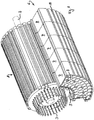
- the Figure 1 shows an electric drive system according to the invention with an electric motor 1 with an output shaft 2 and opposite rods 3 protruding from the stator for energizing the stator.
- the rods can preferably each be assigned to one or more phases, in particular with a phase voltage of less than 60 V.
- the outer lateral surface of the electric motor 1 has grooves 4, here with a dovetail profile, into which corresponding webs 5 on the inner lateral surface of the energy supply 6 shown here only in part can be inserted.
- the energy supply 6 is accommodated in a hollow cylindrical housing, which is divided here both in the axial direction and in the circumferential direction.
- the entire hollow cylindrical housing is formed into a plurality of ring segments 7, of which only those are shown here which lie axially one behind the other at a common circumferential position.
- This common circumferential position here extends over an angular range of 90 degrees, since there is a division in the circumferential direction into 4 segments.
- Heat pipes can be arranged in the grooves 9 in order to transfer heat generated at the end in power electronics (not shown here) and the heat of the motor 1 to the side of the output shaft 2.
- the ring segments 7 can also have grooves 10 on the outside, in which heat pipes can lie for heat transport.
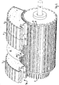
- the Figure 2 shows a view that clarifies that connecting boards 11 (in particular at least one) can be provided between two adjacent segments 7, in particular between each pair of two adjacent segments 7, which are axially one behind the other at a common circumferential position, in order to connect the battery cells within each To make segment 7 and between the adjacent segments 7. For example, all battery cells contained in the segments can be connected in series.
- Each segment can have its own assigned board
- the connecting plate 11 which is designed in the form of an annular segment, has contacts 12 which can be connected to a plate, not shown here, which can be located in the recess region 13, which extends in the axial direction and at an end lying in the circumferential direction 7a of each segment and is thus also arranged between two successive segments in the circumferential direction.
- the circuit board, not shown, can take over the battery management of the battery cells here.
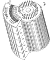
- Figure 3 shows the arrangement of a control board 14, which extends at least substantially over the same angular range as in the segment 7 and thus has the shape of a circular ring segment.
- the one shown here Control board 14 comprises power electronics for controlling those rods 3 of the stator which are in contact with the board 14 in the same angular range.
- the control board covers part of the end face of the motor 3 and essentially completely the end face of the last or first segment 7.
- three further identical functional units can be mounted on the motor 1, as a result of which the total electrical capacity can be quadrupled, as can the torque of the motor.
- four realized functional units form an energy supply in the sense of the invention, which extends in the circumferential direction over a full 360 degrees, in particular in this case additionally forms a fourfold redundancy.
- the invention is not limited to the 4-fold segmentation shown here. Both more and fewer segments can be provided.
Description
Die Erfindung betrifft ein Elektro-Antriebssystem, insbesondere für Fahrzeuge, umfassend einen Elektromotor und eine Energieversorgung, insbesondere einschließlich Pulswechselrichter und Leistungselektronik, wobei die Energieversorgung radial außen am Elektromotor anliegend und in Umfangsrichtung um den Elektromotor herum angeordnet ist.The invention relates to an electric drive system, in particular for vehicles, comprising an electric motor and a power supply, in particular including a pulse-controlled inverter and power electronics, the power supply being arranged radially on the outside of the electric motor and in the circumferential direction around the electric motor.
Das Dokument
Heutige Antriebssysteme dieser Art umfassen im Bereich der Energieversorgung üblicherweise Energiespeicherzellen, wie beispielsweise Batterien, worunter insbesondere solche der wiederaufladbaren Art verstanden werden, wie z.B. Lithium-Polymer-Akkus. Zusätzlich sind regelmäßig in einem solchen Antriebssystem Pulswechselrichter vorgesehen.Today's drive systems of this type usually include energy storage cells, such as batteries, in the field of energy supply, which are understood to mean in particular those of the rechargeable type, such as Lithium polymer batteries. In addition, pulse inverters are regularly provided in such a drive system.
Hierbei haben die Energiespeicherzellen die Aufgabe, die für den Betrieb des Antriebssystems, insbesondere das Fahren eines Fahrzeugs benötigte Energie bereitzustellen bzw. während des Ladens zu speichern. Der Pulswechselrichter wandelt die von der Batterie bereitgestellte Gleichspannung in eine üblicherweise dreiphasige Wechselspannung, mit der ein Elektromotor, z.B. eine Synchron- oder Asynchronmaschine dann über eine Leistungselektronik betrieben wird, welche die Ansteuerung der Statorwicklungen übernimmt.The energy storage cells have the task of providing the energy required for operating the drive system, in particular driving a vehicle, or of storing it during charging. The pulse inverter converts the DC voltage provided by the battery into a customary one three-phase AC voltage, with which an electric motor, for example a synchronous or asynchronous machine, is then operated via power electronics, which takes over the control of the stator windings.
Die Energiespeicherzellen, Pulswechselrichter und Leistungselektronik werden hierbei meist unabhängig voneinander gefertigt und bilden selbstständige Einheiten, die über Kabelbäume miteinander verbunden werden. Hierbei ist bei der Systemauslegung immer ein geeigneter Kompromiss zwischen der Größe der Ströme, die in dem System fließen und der Spannungslage zu finden.The energy storage cells, pulse inverters and power electronics are usually manufactured independently of one another and form independent units that are connected to one another via cable harnesses. When designing the system, there is always a suitable compromise between the size of the currents flowing in the system and the voltage level.
Für ein Antriebssystem mit einer Leistung von z.B. 100kW könnte die Batterie entweder mit einer DC-Spannung von 100V und einem Ausgangsstrom von ca. 1000A ausgelegt werden oder aber mit höheren Spannungen und entsprechend niedrigeren Strömen.For a drive system with a performance of e.g. 100kW, the battery could either be designed with a DC voltage of 100V and an output current of approx. 1000A or with higher voltages and correspondingly lower currents.
Beispielsweise im Anwendungsgebiet der heutigen Elektrofahrzeuge hat sich zur Zeit eine Spannungslage von ca. 400-600V durchgesetzt, was zu Strömen in Bereich von einigen hundert Ampere führt. Niedrige Spannungen und höhere Ströme sind in den bisherigen Antriebssystemen nicht sinnvoll umsetzbar, da die Querschnitte der stromführenden Kabel und Motorwicklungen in diesem Fall massiv ansteigen müssten, was zu einer Erhöhung des Fahrzeuggewichts und der Kosten führen würde.For example, in the field of application of today's electric vehicles, a voltage level of approx. 400-600V has currently established itself, which leads to currents in the range of a few hundred amperes. Low voltages and higher currents cannot be sensibly implemented in the previous drive systems, since the cross sections of the live cables and motor windings would have to increase massively in this case, which would lead to an increase in vehicle weight and costs.
Die Spannungslage von typ. > 400V führt weiterhin im bisherigen Stand der Technik zu erheblichen Anforderungen hinsichtlich der elektrischen Sicherheit solcher Systeme und bringt erhebliche Aufwände bzgl. Isolation der einzelnen Komponenten vom Fahrzeug-Chassis und der entsprechenden Isolationsüberwachung mit sich.The voltage level of typically> 400V continues to result in the current state of the art in considerable requirements with regard to the electrical safety of such systems and entails considerable effort with regard to the insulation of the individual components from the vehicle chassis and the corresponding insulation monitoring.
Diese Aufwände könnten unter Bezug auf VDE-Normen erst für Spannungen <60V reduziert werden. Die jedoch dabei benötigten deutlich erhöhten Ströme können jedoch bei den bisherigen Antriebssystemen aufgrund der zu überbrückenden Strecken und der dafür nötigen Leitungsquerschnitte nicht wirtschaftlich gehandhabt werden.This effort could only be reduced for voltages <60V with reference to VDE standards. However, the significantly increased currents required here cannot be handled economically in the previous drive systems due to the distances to be bridged and the line cross sections required for this.
Ein wesentliches Kriterium bei der Auslegung eines elektrischen oder hybriden Antriebs für Fahrzeuge ist dabei die volumetrische Energie- bzw. Leistungsdichte, d.h. das Volumen des elektrischen Antriebsstrangs bezogen auf den Energieinhalt (der ein Maß für die Reichweite des Fahrzeugs darstellt) bzw. bezogen auf das Gewicht des Antriebsstrangs.An essential criterion when designing an electric or hybrid drive for vehicles is the volumetric energy or power density, i.e. the volume of the electric drive train based on the energy content (which is a measure of the range of the vehicle) or based on the weight of the drive train.
Vor dem Hintergrund vorgenannter Erläuterungen ist es eine Aufgabe der Erfindung einen solchen elektrischen Antrieb möglichst kompakt zu fertigen (d.h. mit minimalem Volumen)und so ein Antriebssystem bereit zu stellen, das die zu überbrückenden Distanzen zwischen der Energieversorgung und dem betriebenen Elektromotor reduziert. Weiterhin ist es bevorzugt auch eine Aufgabe der Erfindung, ein Antriebssystem zu schaffen, das eine Redundanz in der Energieversorgung bereitstellt und weiter bevorzugt mit gegenüber der heutigen typischen Spannungslage deutlich verringerten Spannungen betrieben werden kann, insbesondere mit Phasenspannungen kleiner gleich 60 Volt, um die Isolationsanforderungen zu minimieren und so ebenfalls die erforderlichen Abstände zwischen den einzelnen Sub-Komponenten und damit in letzter Konsequenz auch die Kosten.Against the background of the aforementioned explanations, it is an object of the invention to produce such an electric drive as compactly as possible (i.e. with a minimal volume) and thus to provide a drive system which reduces the distances to be bridged between the energy supply and the operated electric motor. Furthermore, it is also preferably an object of the invention to provide a drive system which provides redundancy in the energy supply and can be operated more preferably with voltages which are significantly reduced compared to today's typical voltage level, in particular with phase voltages of less than or equal to 60 volts, in order to meet the insulation requirements minimize and thus also the required distances between the individual sub-components and ultimately the costs.
Diese Aufgabe wird erfindungsgemäß durch ein Elektro-Antriebssystem nach Anspruch 1 gelöst.This object is achieved by an electric drive system according to claim 1.
Die Erstreckung der Energieversorgung, bzw. eines diese aufnehmenden Gehäuses muss nicht zwingend über den vollen Umfangswinkel von 360 Grad erfolgen, ist jedoch bevorzugt vorgesehen, so dass in diesem Fall ein Elektromotor vollumfänglich von der Energieversorgung umgeben ist.The extension of the energy supply or a housing receiving it does not necessarily have to be over the full circumferential angle of 360 degrees, but is preferably provided so that in this case an electric motor is completely surrounded by the energy supply.
Der wesentliche Gedanke der Erfindung ist es, die Energieversorgung örtlich so nah wie möglich an den Elektromotor heranzuführen. Durch die Anordnung radial außen am Elektromotor, insbesondere also an dessen äußerer Gehäusemantelfläche, die - abgesehen von einer evtl. Oberflächenkonturierung / -strukturierung - regelmäßig zylindrisch ausgebildet ist, besteht allenfalls noch die Notwendigkeit, abgesehen von inneren Stromwegen, die Energie aus der Energieversorgung über die axiale Länge des Elektromotors und ggfs. die radiale Beabstandung zwischen den Statoranschlüssen und der Energieversorgung zu führen. Die zu überbrückenden Wege sind also ersichtlich gegenüber dem Stand der Technik deutlich reduziert.The essential idea of the invention is to bring the energy supply locally as close as possible to the electric motor. Due to the arrangement radially on the outside of the electric motor, in particular on its outer casing surface, which - apart from a possible surface contouring / structuring - is regularly cylindrical, there is still the need, apart from internal current paths, for the energy from the energy supply via the axial length of the electric motor and, if necessary, the radial spacing between the stator connections and the power supply. The paths to be bridged are clearly reduced compared to the prior art.
Selbst bei einem Betrieb eines solchen Antriebssystems mit den bislang verwendeten Spannungen ergeben sich bereits deutliche Vorteile, wobei die Erfindung jedoch auch die Möglichkeit erschließt, die Spannungslage abzusenken, da damit bedingte erhöhte Leiterquerschnitte zur Führung gleichbleibender Leistung in den verkürzten Leitungswegen handhabbar werden.Even when operating such a drive system with the voltages used so far, there are already clear advantages, but the invention also opens up the possibility of lowering the voltage level, since this increases the conductor cross-sections required for guiding constant power in the shortened line paths.
Die Erfindung sieht dabei vor, die Energieversorgung, insbesondere die dafür benötigten Energiespeicherzellen (Batteriezellen) in einem hohlzylindrischen Gehäuse anzuordnen, in dessen inneren hohlen Bereich der Elektromotor angeordnet ist. Bevorzugt liegen dabei die Zylinderachse der Energieversorgung, bzw. von dessen Gehäuse und die Motorachse kollinear. Weiterhin bevorzugt ist die Anordnung so, dass die axiale Länge der Energieversorgung, bzw. von dessen Gehäuse zumindest im Wesentlichen gleich der axialen Länge des Motorgehäuses ist, allenfalls bis zu 150% von dessen Länge entspricht.The invention provides for the energy supply, in particular the energy storage cells (battery cells) required for this, to be in a hollow cylindrical one Arrange housing, in the inner hollow area of which the electric motor is arranged. The cylinder axis of the energy supply or of its housing and the motor axis are preferably collinear. The arrangement is further preferred such that the axial length of the energy supply, or of its housing, is at least substantially equal to the axial length of the motor housing, possibly up to 150% of its length.
Die erfindungsgemäße Anordnung schafft insgesamt eine handhabbare Einheit, die durch die äußeren Abmessungen der Energieversorgung definiert ist und darin komplett den Elektromotor umfasst, insbesondere auch die gesamte Elektronik zur Steuerung des Elektromotors und für das Energiemanagement der Energiespeicherzellen.Overall, the arrangement according to the invention creates a manageable unit, which is defined by the external dimensions of the energy supply and completely includes the electric motor therein, in particular also the entire electronics for controlling the electric motor and for the energy management of the energy storage cells.
Somit ergibt sich auch eine erhöhte Wartungsfreundlichkeit, da alle wesentlichen Komponenten zum Betrieb lokal konzentiert sind, was auch im bisherigen Spannungsbereich die Isolationsanforderungen reduziert, aufgrund der stärkeren Einkapselung der spannungsführenden Bauteile. Beispielsweise besteht die Möglichkeit in praktisch jeder Werkstatt das komplette Antriebssystem zu tauschen.This also results in an increased ease of maintenance, since all essential components for operation are concentrated locally, which also reduces the insulation requirements in the previous voltage range, due to the stronger encapsulation of the live components. For example, it is possible to replace the complete drive system in practically every workshop.
Die Erfindung kann in bevorzugter Ausführung vorsehen, dass das hohlzylindrische Gehäuse eine Vielzahl von Ausnehmungen aufweist, in welchen Energiespeicherzellen aufgenommen sind oder zumindest aufnehmbar sind. Diese Ausnehmungen, insbesondere auch weitere zum Betrieb benötigte Baugruppen sind dabei bevorzugt komplett zwischen Innenwandung und Außenwandung des hohlzylindrischen Gehäuses angeordnet.In a preferred embodiment, the invention can provide that the hollow cylindrical housing has a plurality of recesses, in which energy storage cells are accommodated or at least can be accommodated. These recesses, in particular also further assemblies required for operation, are preferably arranged completely between the inner wall and outer wall of the hollow cylindrical housing.
Beispielsweise kann es vorgesehen sein, die Ausnehmungen zylindrisch auszugestalten, so dass am Markt übliche Batteriezellen mit standardisierten Baugrößen darin aufgenommen werden können, z.B. solche, wie Sie aus Laptop-Akkus bekannt sind. Die Ausnehmungen sind dabei bevorzugt so orientiert, dass diese sich in axialer Richtung erstrecken. In den Ausnehmungen können bevorzugt die Batteriezellen in beiden möglichen, sich um 180 Grad unterscheidenden Einbaulagen angeordnet werden, was die gewünschte elektrische Verschaltung vereinfacht.For example, it can be provided to design the recesses in a cylindrical manner, so that battery cells with standard sizes, which are common on the market, can be accommodated therein, for example those as are known from laptop batteries. The recesses are preferably oriented so that they extend in the axial direction. In the recesses, the battery cells can preferably in both possible, 180 degrees differing installation positions can be arranged, which simplifies the desired electrical connection.
Die Erfindung sieht weiterhin vor, dass das hohlzylindrische Gehäuse zur Bildung von Untereinheiten unterteilt ist. Hierdurch ergibt sich zum einen eine größere Wartungsfreundlichkeit und Kostenreduzierung, z.B. wenn defekte Teile ausgetauscht werden müssen.The invention further provides that the hollow cylindrical housing is subdivided to form subunits. On the one hand, this results in greater ease of maintenance and cost reduction, e.g. if defective parts have to be replaced.
Zum anderen erschließt sich jedoch auch die Möglichkeit die Energiespeicherzellen (Batteriezelle) innerhalb einer Untereinheit und/oder die Untereinheiten untereinander je nach Wunsch elektrisch parallel oder in Reihe zu verschalten.On the other hand, however, it is also possible to connect the energy storage cells (battery cell) within a subunit and / or the subunits to one another electrically in parallel or in series, as desired.
Die Erfindung sieht hierfür in einer möglichen Alternativen vor, dass in der axialen Richtung das hohlzylindrische Gehäuse der Energieversorgung in mehrere Ringelemente unterteilt ist, wobei jedes Ringelement in Umfangsrichtung in wenigstens zwei Segmente unterteilt ist. Z.B. kann dabei die axiale Länge jedes Ringelementes angepasst sein, um genau eine axial liegende Energiespeicherzelle (Batteriezelle) in einer jeweiligen zylindrischen Ausnehmung aufzunehmen. Die axiale Länge eines Ringelementes kann z.B. genau gleich oder auch (etwas) kleiner sein als die axiale Länge einer Energiespeicherzelle. Ebenso kann die axiale Länge auf ein Vielfaches (wenigstens Zweifaches) der axialen Länge einer Energiespeicherzelle angepasst sein. Ein jedes solches Ringelement kann ein in sich abgeschlossenes Energiespeichermodul ausbilden, insbesondere mit welchem alleine bereits der Betrieb des Elektromotors möglich sein kann.In one possible alternative, the invention provides for the hollow cylindrical housing of the energy supply to be divided into a plurality of ring elements in the axial direction, each ring element being divided into at least two segments in the circumferential direction. E.g. The axial length of each ring element can be adapted to receive exactly one axially lying energy storage cell (battery cell) in a respective cylindrical recess. The axial length of a ring element can e.g. be exactly the same or (somewhat) smaller than the axial length of an energy storage cell. Likewise, the axial length can be adapted to a multiple (at least twice) the axial length of an energy storage cell. Each such ring element can form a self-contained energy storage module, in particular with which alone the operation of the electric motor can be possible.
Die Erfindung sieht in einer anderen möglichen Alternativen vor, dass das hohlzylindrische Gehäuse in Umfangsrichtung in wenigstens zwei Segmente unterteilt ist. Jedes Segment kann eine Winkelerstreckung von 360° / Anzahl der Segmente aufweisen. Ein jedes solches sich über die gesamte axiale Länge des hohlzylindrischen Gehäuses erstreckende Segment kann ein in sich abgeschlossenes Energiespeichermodul ausbilden, insbesondere mit welchem alleine bereits der Betrieb des Elektromotors möglich sein kann.In another possible alternative, the invention provides that the hollow cylindrical housing is divided into at least two segments in the circumferential direction. Each segment can have an angular extent of 360 ° / number of segments. Each such segment, which extends over the entire axial length of the hollow cylindrical housing, can form a self-contained energy storage module, in particular with which the operation of the electric motor alone can be possible.
Die bevorzugte Alternative ist diejenige, bei der die Unterteilung des hohlzylindrischen Gehäuses in axialer Richtung undin Umfangsrichtung kombiniert ist, so dass jedes vorgenannte Ringelement in Umfangsrichtung in wenigstens zwei Segmente unterteilt ist. Jedes (Ringelemente-) Segment kann wiederum eine Winkelerstreckung von 360° / Anzahl der Segmente aufweisen. Hier bildet die Gesamtanzahl aller in axialer Richtung an einer gemeinsamen Umfangsposition hintereinanderliegenden Segmente, insbesondere durch elektrischen Verschaltung, ein Energiespeichermodul aus, mit welchem alleine bereits der Betrieb des Elektromotors möglich ist. Es ergibt sich hierdurch eine Anzahl von Energiespeichermodulen, die der Anzahl der Segmente (pro Ringelement) entspricht.The preferred alternative is the one in which the subdivision of the hollow cylindrical housing is combined in the axial direction and in the circumferential direction, so that each aforementioned ring element is divided into at least two segments in the circumferential direction. Each (ring element) segment can in turn have an angular extent of 360 ° / number of segments. Here, the total number of all segments lying behind one another in the axial direction at a common circumferential position, in particular by means of electrical interconnection, forms an energy storage module with which the operation of the electric motor alone is already possible. This results in a number of energy storage modules which corresponds to the number of segments (per ring element).
Bei einer solchen Konstruktion weist das Gehäuse der Energieversorgung somit insgesamt eine Anzahl von Untereinheiten auf, die der Anzahl der Ringelemente multipliziert mit der Anzahl der Segmente pro Ringelement entspricht. Eine entsprechende Vielfalt möglicher elektrischer Verschaltungen kann hierdurch realisiert werden.With such a construction, the housing of the energy supply thus has a total of a number of subunits, which corresponds to the number of ring elements multiplied by the number of segments per ring element. A corresponding variety of possible electrical interconnections can be implemented in this way.
In einer weiterhin bevorzugten Ausführung der vorgenannten Konstruktion kann es vorgesehen sein, dass zwischen je zwei benachbart axial hintereinander liegenden Segmenten von Ringelementen wenigstens eine Verbindungsplatine angeordnet ist. Es kann jedem Segment eine eigene Verbindungsplatine zugeordnet sein.In a further preferred embodiment of the aforementioned construction, it can be provided that at least one connecting plate is arranged between two adjacent axially successive segments of ring elements. Each segment can be assigned its own connection board.
Durch eine solche Verbindungsplatine können die Energiespeicherzellen eines jeden Segmentes untereinander kontaktiert sein, z.B. alle in Reihe geschaltet sein oder alle parallel geschaltet sein oder in Gruppen unterteilt sein, wobei in verschiedenen Gruppen die Energiespeicherzellen unterschiedlich verschaltet sein können (Reihe oder parallel) oder bei gleicher gewählten Verschaltung in den Gruppen bei den verschiedenen Gruppen unterschiedlich hinsichtlich der Einbaulage orientiert sein können.With such a connection board, the energy storage cells of each segment can be contacted, e.g. all be connected in series or all connected in parallel or divided into groups, the energy storage cells being able to be connected differently in different groups (series or parallel) or, with the same selected connection in the groups, different orientation of the groups in the different groups .
Ein jeweilige Verbindungsplatine kann auch die Verschaltung zwischen den beiden axial benachbarten Segmenten vornehmen, z.B. diese in Reihe oder wiederum parallel schalten. Mit den Verbindungsplatinen können bevorzugt so die Energiespeicherzellen wenigstens einer Teilanzahl, bevorzug aller an einer gemeinsamen Umfangsposition axial hintereinander angeordneten Segmente elektrisch in Reihe geschaltet sind. In einer möglichen Ausführung kann es vorgesehen sein, dass sich über die axiale Länge aller Segmente an derselben Umfangsposition sich z.B. eine Spannung ergibt, die der Summe der in den Segmenten verwendeten Energiespeicherzellen entspricht. Bei dieser Ausführung würden hingegen die Pole an unterschiedlichen axialen Seiten liegen. Beispielsweise kann es in einer bevorzugten Ausführung vorgesehen sein, dass in einem jeden Segment zwei Gruppen von Energiespeicherzellen gebildet sind, wobei in jeder Gruppe die Energiespeicherzellen parallel geschaltet sind. Eine Gruppe kann z.B. radial innen und eine radial außen liegend angeordnet sein. Die Energiespeicherzellen können in den verschiedenen Gruppen bevorzugt um 180 Grad unterschiedliche Orientierung der Einbaulage aufweisen. Das kann den Vorteil erschließen, in axialer Richtung über die Segmente gemeinsamer Umfangsposition hinweg die parallel geschalteten Energiespeicherzellen der einen Gruppe und die parallel geschalteten Energiespeicherzellen der anderen Gruppe unabhängig voneinander in Reihe zu verschalten und hierbei die beiden Pole an derselben axialen Seite zugänglich zu haben, insbesondere an der Seite, an welcher gemäß den nachfolgenden Ausführungen wenigstens eine Steuerplatine, z.B. mit Leistungselektronik und/oder Pulswechselrichter vorgesehen ist.A respective connection board can also make the connection between the two axially adjacent segments, for example these in series or again connect in parallel. With the connection boards, the energy storage cells of at least a number of parts, preferably all of the segments arranged axially one behind the other at a common circumferential position, can thus preferably be electrically connected in series. In one possible embodiment, it can be provided that, for example, a voltage results across the axial length of all segments at the same circumferential position, which corresponds to the sum of the energy storage cells used in the segments. In this version, however, the poles would be on different axial sides. For example, it can be provided in a preferred embodiment that two groups of energy storage cells are formed in each segment, the energy storage cells being connected in parallel in each group. A group can, for example, be arranged radially inside and a group lying radially outside. The energy storage cells in the different groups can preferably have a different orientation of the installation position by 180 degrees. This can open up the advantage of connecting the parallel-connected energy storage cells of one group and the parallel-connected energy storage cells of the other group independently of one another in series in the axial direction over the segments of common circumferential position, and in this case having the two poles accessible on the same axial side, in particular on the side on which, according to the following explanations, at least one control board, for example with power electronics and / or pulse inverter, is provided.
Alle axialen hintereinander liegenden Segmente (der Ringe) an einer gemeinsamen Umfangsposition bilden so wiederum ein Energiespeichermodul mit an einer Seite zugänglichen Polen, quasi wie ein Batteriepack in der Querschnittsform eines Kreissegmentes.All axial segments (of the rings) lying one behind the other at a common circumferential position thus in turn form an energy storage module with poles accessible on one side, quasi like a battery pack in the cross-sectional shape of a circular segment.
Die Erfindung sieht es vor, dass die gebildeten Energiespeichermodule jeweils zusammen mit einer eigenen Elektronik auf einer Steuerplatine ein jeweiliges autarkes Funktionsmodul bilden, das jeweils alleine ausreicht, um den Motor zu betreiben. Dafür kann die Elektronik einen Pulswechselrichter und Schalter zur Bestromung des Stators umfassen. Es ergibt sich dadurch eine Anzahl von Funktionsmodulen, die der Anzahl der Segmente (pro Ringelement) entspricht.The invention provides that the energy storage modules that are formed, together with their own electronics on a control board, form a respective autonomous function module, each of which alone is sufficient to operate the motor. For this, the electronics can use a pulse inverter and switch Power supply to the stator include. This results in a number of function modules which corresponds to the number of segments (per ring element).
Hierdurch wird auch eine Redundanz geschaffen, da ein Antriebssystem dieser Art auch betriebsbereit ist, wenn z.B. ein Segment oder sogar alle an einer gemeinsamen Umfangsposition hintereinander liegenden Segmente (und damit ein Funktionsmodul) ausfallen, da hierdurch nicht die Betriebsspannung und die Statoransteuerung entfällt, sondern sich nur die Ladekapazität verringert, in Verbindung mit einem Fahrzeug also nur dessen Reichweite.This also creates redundancy, since a drive system of this type is also ready for operation if e.g. one segment or even all segments lying behind one another at a common circumferential position (and thus a functional module) fail, since this does not eliminate the operating voltage and the stator control, but rather only reduces the charging capacity, in connection with a vehicle only its range.
Es kann eine Elektronik vorgesehen sein, die die Funktion jedes Funktionsmoduls prüft und bei festgestelltem Defekt dieses komplett abschaltet. Die übrigen Funktionsmodule bleiben dabei betriebsbereit und damit das Antriebssystem insgesamt, lediglich unter Reduktion der Reichweite und des Drehmomentes.Electronics can be provided which check the function of each function module and switch it off completely if a defect is found. The remaining function modules remain ready for operation and thus the drive system as a whole, only with a reduction in range and torque.
Bevorzugt ist die Form einer jeweiligen Verbindungsplatine an die Form der jeweiligen Segmente angepasst, bevorzugt so, dass diese zwar formkongruent zu den Segmenten ist, jedoch etwas kleiner, um von den Segmenten umschlossen zu werden, ohne dass die Verbindungsplatine von außer halb des Gehäuses der Energieversorgungseinheit zugänglich ist, zumindest nicht ohne die Segmente voneinander zu separieren, die in jeglicher Ausführung bevorzugt im Betriebszustand bündig und einander kontaktierend verbunden sind. Beispielsweise kann so die Verbindungsplatine kreisringsegmentförmig ausgebildet sein. An einem in Umfangsrichtung liegenden Ende der Verbindungsplatine kann diese Kontakte aufweisen, um mit anderen Komponenten elektrisch verbunden zu werden, z.B. mit der nachfolgend beschriebenen Platine.The shape of a respective connection board is preferably adapted to the shape of the respective segments, preferably in such a way that, although it conforms to the segments, it is somewhat smaller in order to be enclosed by the segments without the connection board from outside the housing of the power supply unit is accessible, at least not without separating the segments, which in each embodiment are preferably connected flush and in contact with one another in the operating state. For example, the connection board can be designed in the form of a circular segment. At a circumferential end of the connection board, this can have contacts in order to be electrically connected to other components, e.g. with the circuit board described below.
Die Erfindung kann in einer Weiterbildung vorsehen, dass in einem Bereich zwischen je zwei in Umfangsrichtung benachbarten Segmenten (an einer gemeinsamen axialen Position) bei allen axial hintereinander liegenden Segmenten einer gemeinsamen Umfangsposition eine sich achsparallel erstreckende Platine angeordnet ist, insbesondere die sich im Wesentlichen über die gesamte axiale Länge der hohlzylindrischen Energieversorgung erstreckt. Diese Platine kann mit jeder vorgenannten Verbindungsplatine zwischen zwei benachbart axial hintereinanderliegenden Segmenten elektrisch verbunden sein.In a further development, the invention can provide that in a region between each two adjacent segments in the circumferential direction (at a common axial position) an axially parallel plate is arranged in all axially successive segments of a common circumferential position, in particular essentially over extends the entire axial length of the hollow cylindrical energy supply. This board can be electrically connected to each of the aforementioned connection boards between two adjacent axially successive segments.
Diese Platine kann bevorzugt eine Elektronik zum Energiespeicherzellenmanagement, insbesondere zur Prüfung der insbesondere in jedem Segment oder in allen Segmenten einer gemeinsamen Umfangsposition gereihten Zellspannungen umfassen. Diese Platine und deren Elektronik kann auch vorgesehen sein, um die zuvor Funktionsprüfung vorzunehmen.This circuit board can preferably comprise electronics for energy storage cell management, in particular for checking the cell voltages, which are arranged in particular in each segment or in all segments of a common circumferential position. This circuit board and its electronics can also be provided in order to carry out the functional test beforehand.
Die Erfindung sieht unabhängig von den möglichen verschiedenen Ausführungen allgemein vor, dass die durch in und mit den Segmenten nach Reihen- und / oder Parallelschaltung der darin enthaltenen Energiespeicherzellen erzeugten Spannungen genutzt werden, um mit wenigstens einer Steuerelektronik die Phasenspannungen für den Motor zu bilden. Eine solche Steuerelektronik wird durch Elektronikkomponenten auf wenigstens einer Steuerplatine gebildet, die stirnseitig des Elektromotor und/oder des Gehäuses der Energieversorgung angeordnet ist, insbesondere auf der von der Motorabtriebswelle abgewandten Seite. Dies hat den Vorteil, dass die statorseitigen Phasenanschlüsse des Elektromotors in axialer Richtung in diese wenigstens eine Steuerplatine kontaktierend eingefügt werden können.Regardless of the possible different designs, the invention generally provides that the voltages generated by in and with the segments after series and / or parallel connection of the energy storage cells contained therein are used to form the phase voltages for the motor with at least one electronic control system. Such control electronics is formed by electronic components on at least one control board, which is arranged on the end face of the electric motor and / or the housing of the energy supply, in particular on the side facing away from the motor output shaft. This has the advantage that the stator-side phase connections of the electric motor can be inserted in an axial direction in this at least one control board.
Die wenigstens eine Steuerplatine ist in zumindest teilweiser Überdeckung der axialen Stirnflächen von der Energieversorgungseinheit (bzw. dessen Gehäuse) und dem Elektromotor angeordnet und eingerichtet, die Energie der Energieversorgungseinheit auf das Statorbestromungssystem des Elektromotors zu verteilen, insbesondere gesteuert oder geregelt zu verteilen.The at least one control board is arranged and arranged in at least partial overlap of the axial end faces of the energy supply unit (or its housing) and the electric motor to distribute the energy of the energy supply unit to the stator energization system of the electric motor, in particular to distribute it in a controlled or regulated manner.
Erfindungsgemäß ist jeweils einem jedem in Umfangsrichtung erstreckten Segment des hohlzylindrischen Gehäuses der Energieversorgung oder jeweils allen an einer gemeinsamen Umfangsposition angeordneten Segmenten von axial hintereinanderliegenden Ringelementen (Energiespeichermodul) eine eigene Steuerplatine zugeordnet, insbesondere die kreisringsegmentförmig ausgebildet ist und die an einen Teil des Statorbestromungssystems angeschlossen ist, insbesondere der sich über denselben Winkelbereich erstreckt, wie das betreffende Segment. Das genannte Energiespeichermodul bildet somit mit der jeweils zugeordneten Steuerplatine das bereits zuvor angesprochene Funktionsmodul, d.h. eine betriebsfertige Einheit zum Betrieb des Motors.According to the invention, a separate control circuit board is assigned to each segment of the hollow cylindrical housing of the energy supply that extends in the circumferential direction or in each case all segments of axially successive ring elements (energy storage module) arranged at a common circumferential position, in particular the annular segment segment and which is connected to a part of the stator lighting system, in particular which extends over the same angular range as the segment in question. Said energy storage module thus forms, with the respectively assigned control board, the functional module already mentioned, ie a ready-to-use unit for operating the motor.
Durch alle den Segmenten jeweils zugeordneten, ggfs. untereinander verbundenen Steuerplatinen ist sodann insgesamt eine GesamtLeistungselektronik zur Steuerung des Elektromotors ausgebildet, an der die jeweiligen Spannungen, insbesondere die jeweiligen gereihten Summenspannungen von den an einer gemeinsamen Umfangsposition axial hintereinanderliegenden Segmenten anliegen. Hierdurch wird der eingangs genannte Vorteil erschlossen, dass der Elektromotor mit der Energie schon alleine der Segmente einer einzigen gemeinsamen Umfangsposition betreibbar ist, da die Gesamtleistungselektronik durch eine Summe einzelner Leistungselektroniken gebildet ist, die jeweils für sich in der Lage sind den Motor zu betreiben. Jede Leistungselektronik umfasst dabei bevorzugt einen Pulswechselrichter.A total of power electronics for controlling the electric motor is then formed by all of the control boards assigned to the segments and possibly connected to one another, to which the respective voltages, in particular the respective summed voltages of the segments lying axially one behind the other at a common circumferential position, are applied. This opens up the advantage mentioned at the outset that the electric motor can be operated with the energy alone of the segments of a single common circumferential position, since the overall power electronics are formed by a sum of individual power electronics which are each capable of operating the motor. Each power electronics preferably includes a pulse inverter.
Eine ganz besonders bevorzugte Ausführungsform der Erfindung kann es vorsehen, dass das Statorbestromungssystem des Elektromotors durch eine Vielzahl bestrombarer Stäbe ausgebildet ist, die sich in axialer Richtung durch den Stator des Elektromotors erstrecken und an einem ihrer Enden mit einem gemeinsamen Kurzschlußring verbunden sind und an dem anderen Ende mit einer Steuerplatine verbunden sind, insbesondere einer Steuerplatine der vorgenannten Art, die stirnseitig angeordnet ist.A very particularly preferred embodiment of the invention can provide that the stator energization system of the electric motor is formed by a plurality of energizable rods which extend in the axial direction through the stator of the electric motor and are connected at one end to a common short-circuit ring and at the other Are connected at the end to a control board, in particular a control board of the aforementioned type, which is arranged on the end face.
Es kann hier vorgesehen sein, dass die Stäbe einer Anzahl von mehr als 3 Phasen, bevorzugt wenigstens 20 Phasen, weiter bevorzugt wenigstens 30 Phasen zugeordnet sind. Durch diese signifikante Erhöhung der Phasenanzahl gegenüber dem Stand der Technik kann erzielt werden, dass die Spannungsdifferenz zwischen zwei Phasen oder einer Phase und Masse kleiner gleich 60 Volt ist. Dies führt zu dem eingangs genannten Vorteil, dass die Isolationsanforderungen deutlich kleiner sind und sich hierdurch insgesamt die Konstruktion vereinfacht und günstiger wird im Vergleich zum Stand der Technik.It can be provided here that the rods are assigned to a number of more than 3 phases, preferably at least 20 phases, more preferably at least 30 phases. As a result of this significant increase in the number of phases compared to the prior art, it can be achieved that the voltage difference between two phases or one phase and ground is less than or equal to 60 volts. This leads to the advantage mentioned at the outset that the Insulation requirements are significantly lower and this simplifies the overall construction and becomes cheaper compared to the prior art.
Wenngleich die Ausbildung des Stators mit Stäben in dieser Ausführung bevorzugt ist, da der Nutfüllfaktor im Stator gegenüber Spulen verbessert ist, kann grundsätzlich eine solche Erhöhung der Phasenanzahl auch mit gewickelten Statorspulen erzielt werden und ist ebenso von der Erfindung umfasst.Although the design of the stator with rods is preferred in this embodiment, since the slot filling factor in the stator is improved compared to coils, such an increase in the number of phases can in principle also be achieved with wound stator coils and is also encompassed by the invention.
Die bevorzugte Verwendung von Stäben führt auch zu dem Vorteil, dass niedrigere Motorinduktivitäten erzeugt werden, so dass die Reduzierung der Phasenspannungen der Beherrschung der Stromanstiegsgeschwindigkeiten zuträglich ist.The preferred use of rods also leads to the advantage that lower motor inductances are generated, so that the reduction in the phase voltages is conducive to the control of the current rise rates.
Die Schalter der Steuerplatine(n) zur Bestromung der Phasenanschlüsse des Stators können vorzugsweise als MOSFETs ausgeführt sind, insbesondere wenn die Betriebsspannung auf weniger als 60V reduziert wird. Die Schalter werden bevorzugt in einer Halbbrücken-Konfiguration betrieben, wobei jede Halbbrücke einen Stab des Motors versorgen kann.The switches of the control board (s) for energizing the phase connections of the stator can preferably be designed as MOSFETs, in particular if the operating voltage is reduced to less than 60V. The switches are preferably operated in a half-bridge configuration, with each half-bridge being able to supply one rod of the motor.
In einer einfachen Ausführungsform der Erfindung kann das Statorbestromungssystems mit elektrischer Masse und einer positiven Versorgungsspannung betrieben werden. Ein bevorzugte Ausführung kann jedoch auch vorsehen, dass der Kurzschlussring an der der Leistungselektronik / Steuerplatine(n) gegenüberliegenden Seite auf Masse liegt und die Stäbe zwischen zwei um Masse herum symmetrische Spannungen geschaltet werden. Damit kann jeder Stab individuell und unabhängig von den anderen Stäben bestromt werden.In a simple embodiment of the invention, the stator lighting system can be operated with electrical ground and a positive supply voltage. A preferred embodiment can, however, also provide that the short-circuit ring is connected to ground on the side opposite the power electronics / control board (s) and the rods are switched between two voltages symmetrical about ground. This means that each rod can be energized individually and independently of the other rods.
In einer bevorzugten Ausführungsform wird die magnetische Polpaarzahl im Rotor des Motors gleich der Anzahl der in Umfangsrichtung liegenden Segmente gewählt, von denen die an einer gemeinsamen Umfangsposition axial hintereinander liegenden Segmente alle elektrisch zu einer zusammenwirkenden Untereinheit zusammengeschaltet sein können, also bevorzugt ein in sich autarke Energieversorgungsuntereinheit der gesamten Energieversorgung bildet.In a preferred embodiment, the number of magnetic pole pairs in the rotor of the motor is selected to be equal to the number of segments lying in the circumferential direction, of which the segments lying axially one behind the other at a common circumferential position can all be electrically connected to form a interacting subunit, that is to say preferably a self-sufficient energy supply subunit of the entire energy supply.
Die Leistungselektronik wird ebenfalls in eine entsprechende Anzahl von Subeinheiten unterteilt, wie es vorangehend anhand der mehreren Steuerplatinen erläutert wurde.The power electronics are also subdivided into a corresponding number of subunits, as was explained above on the basis of the several control boards.
Dabei können räumlich an einer gemeinsamen Umfangsposition liegende Einheiten von Segmenten und Steuerplatinen zu Funktionsmodulen zusammengefasst werden, die unabhängig voneinander betrieben und somit als Subantriebs-Module angesehen werden können.Units of segments and control boards located spatially at a common circumferential position can be combined to form functional modules which can be operated independently of one another and can therefore be regarded as sub-drive modules.
Bevorzugt kann es dabei vorgesehen sein, dass sich im Betrieb die Drehmomente der Funktionsmodule zu einem Gesamtdrehmoment für den Antrieb addieren, die Einzel-Drehmomente der jeweiligen Funktionseinheiten müssen jedoch nicht unbedingt identisch sein. Dieses Konzept bietet über die bloße Integration von Motor, Leistungselektronik und Batterie hinaus folgende bereits eingang angedeutete Vorteile:
- 1.) bei einem Ausfall eines Funktionsmoduls (zum Beispiel alle axial hintereinander liegenden Segmente einer Umfangsposition , deren Verbindungsplatinen, Batteriemanagementplatine und stirnseitige Steuerplatine) können die verbleibenden Funktionsmodule weiterhin betrieben werden, was einen Gesamtsystemausfall verhindert und lediglich zu einer Leistungs- bzw. Reichweiteneinbuße führt
- 2.) Da Batteriezellen unterschiedlich altern, ist im Laufe der Zeit mit unterschiedlichen Zellkapazitäten allein aufgrund von Streuung zu rechnen. Innerhalb eines Funktionsmoduls der Energieversorgung wird diese Streuung bevorzugt durch sog. passives Balancing ausgeglichen, d.h. (vereinfacht ausgedrückt) zu hoch geladene Zellen werden auf das Niveau der niedriger geladenen Zellen entladen. Alternativ kann innerhalb eines Funktionsmoduls das Balancing auch aktiv erfolgen, d.h. die Energie von zu hoch geladenen Zellen wird auf niedriger geladene Zellen mittels induktiven oder kapazitiven Verfahren übertragen.
- 1.) in the event of a failure of a function module (for example, all axially consecutive segments of a circumferential position, their connection boards, battery management board and front-side control board), the remaining function modules can continue to be operated, which prevents an overall system failure and only leads to a loss in performance or range
- 2.) Since battery cells age differently, different cell capacities can be expected over time due to scatter alone. Within a function module of the energy supply, this spread is preferably compensated for by so-called passive balancing, ie (to put it simply) cells that are overcharged are discharged to the level of the cells with a lower charge. Alternatively, balancing can also take place actively within a function module, ie the energy from cells that are overcharged is transferred to cells with a lower charge by means of inductive or capacitive methods.
Zwischen den Funktionsmodulen kann der Angleich allerdings auch über die Aufteilung der Gesamtdrehmoments auf die einzelnen Funktionsmodule erfolgen.However, the adjustment between the function modules can also take place by distributing the total torque to the individual function modules.
Zur Bestimmung des Lade- und Alterungszustands der Energiespeicherzellen / Batteriezellen sowie zur Einstellung des Drehmoments des Motors kann es bevorzugt vorgesehen sein, den Strom in der Energieversorgungseinheit, bevorzugt separat in jedem Funktionsmodul sowie in jedem einzelnen Stab zu überwachen.In order to determine the state of charge and aging of the energy storage cells / battery cells and to set the torque of the motor, it can preferably be provided to monitor the current in the energy supply unit, preferably separately in each function module and in each individual rod.
Hierzu kann die Blechung des Motors durch weitere Bleche mit einem kleineren Innendurchmesser ergänzt werden, bei welchen die Nut bis zum Innendurchmesser verlängert ist. Hierdurch kann ein Hall-Sensor direkt von der Leistungselektronik in die Nut gesteckt werden. Der Sensor ist somit in den magnetischen Kreis um den jeweiligen Stab herum eingebunden, magnetisch störfest verbaut und gleichzeitig auf kürzest möglichem Weg mit der Auswerteeinheit, z.B. einem AD-Wandler verbunden.For this purpose, the sheet metal of the motor can be supplemented by further sheets with a smaller inside diameter, in which the groove is extended up to the inside diameter. This enables a Hall sensor to be inserted directly into the groove by the power electronics. The sensor is thus integrated into the magnetic circuit around the respective rod, installed magnetically interference-free and at the same time in the shortest possible way with the evaluation unit, e.g. connected to an AD converter.
Die Messung des Stroms in der Energieversorgung, bevorzugt jedem Funktionsmodul kann über Durchkontaktierungen in den Verbindungsplatinen erfolgen. Wenn ein Strom über diese fließt, so erzeugt dieser Strom einen Spannungsabfall, welcher im Batterie-Management-System ausgewertet wird. Somit dienen die Verbindungsplatinen nicht nur der Verbindung zwischen je zwei axial hintereinander liegenden Segmenten und der Herausführung der Zellspannungen, sondern erfüllen gleichzeitig die Aufgabe der Stromsensierung.The measurement of the current in the power supply, preferably each function module, can be carried out via plated-through holes in the connection boards. If a current flows through this, this current generates a voltage drop, which is evaluated in the battery management system. Thus, the connection boards not only serve to connect two segments lying axially one behind the other and to lead out the cell voltages, but also fulfill the task of current sensing.
Es kann weiterhin vorgesehen sein, am Kurzschlussring zusätzlich einen zentralen Stromsensor anzuordnen, der den Strom vom Kurzschlussring gegen eine Referenz, z.B. ein Fahrzeugchassis misst. Im "Gut- Fall" ist der Strom durch diesen Sensor gleich der Summe der Ströme durch alle Stäbe, somit kann eine Diagnose, der einzelnen Stromerfassungseinheiten an den Stäben vorgenommen werden. Stimmt der an dem zentralen Sensor gemessene Wert nicht mit der Summe der Stabströme überein, so wird ein Fehler diagnostiziert.It can also be provided to additionally arrange a central current sensor on the short-circuit ring, which measures the current from the short-circuit ring against a reference, for example a vehicle chassis. In the "good case", the current through this sensor is equal to the sum of the currents through all the rods, so that a diagnosis of the individual current detection units can be carried out on the rods. If the value measured at the central sensor does not match the sum of the rod currents, an error is diagnosed.
Bei einer korrekt funktionierenden Regelung ist darüber hinaus der Strom durch den am Kurzschlussring angeordneten Sensor Null.If the control functions correctly, the current through the sensor arranged on the short-circuit ring is also zero.
Zur Entwärmung (Kühlung) des Systems kann es vorgesehen werden, die im Elektromotor und der Leistungselektronik auf der oder den Steuerplatinen entstehende Wärme getrennt von der in der Energieversorgung, insbesondere in den Segmenten entstehende Wärme herauszuführen und eine möglichst geringe thermische Kopplung zwischen dem zylindrischen Gehäuse der Energieversorgung und den anderen beschriebenen Komponenten zu realisieren. Damit wird sichergestellt, dass die Motorwärme nicht zur Aufheizung der Energieversorgung und so zu einer beschleunigten Degradation der Batteriezellen führt.For cooling (cooling) of the system, it can be provided to separate the heat generated in the electric motor and the power electronics on the control board or boards from the heat generated in the power supply, in particular in the segments, and to minimize the thermal coupling between the cylindrical housing Realize energy supply and the other components described. This ensures that the engine heat does not heat up the energy supply and thus accelerate the degradation of the battery cells.
Hierfür kann es vorgesehen sein, dass die Energieversorgung und der Elektromotor zueinander wärmetechnisch isoliert sind, insbesondere durch eine radialen Beabstandung, bevorzugt über welche hinweg die Gehäuse von der Energieversorgung und des Elektro-Motors nur durch Stege verbunden sind, welche also eine statische Anbindung ermöglichen, aber nur vergleichsweise wenig Wärmeübertrag zulassen.For this purpose, it can be provided that the energy supply and the electric motor are thermally insulated from one another, in particular by a radial spacing, preferably over which the housings are only connected by webs from the energy supply and the electric motor, which therefore enable a static connection, but only allow relatively little heat transfer.
Es kann insbesondere in Kombination mit der wärmetechnischen Entkopplung, allerdings auch unabhängig von dieser das hohlzylindrische Gehäuse der Energieversorgung, insbesondere jedes Segment in axialer Richtung auf die äußere Mantelfläche des Elektromotors aufsteckbar oder aufschiebbar sein, insbesondere mittels radialen Stegen (z.B. den vorgenannten), die zumindest endseitig in axialen Führungsnute gleitend eingreifen.In particular in combination with the thermal decoupling, but also independently of this, the hollow cylindrical housing of the energy supply, in particular each segment, can be plugged on or pushed on in the axial direction onto the outer lateral surface of the electric motor, in particular by means of radial webs (for example the aforementioned), which at least Slidingly engage at the ends in the axial guide groove.
Der Elektromotor und die Energieversorgung weisen bevorzugt jeweils eine eigene und voneinander unabhängige Entwärmungssysteme auf, insbesondere durch Heatpipes, die sich axial durch den Elektro-Motor und/oder die Energieversorgung erstrecken.The electric motor and the energy supply preferably each have their own, independent cooling systems, in particular through heat pipes which extend axially through the electric motor and / or the energy supply.
Der Gesamtaufbau an Heatpipes kann 2-lagig ausgeführt sein, mit einer ersten Innenlage am äußeren Umfang des Elektromotors, die mit diesem sowie der Leistungselektronik thermisch verbunden ist.The overall structure of heat pipes can be made in two layers, with a first inner layer on the outer circumference of the electric motor, which is thermally connected to this and the power electronics.
Es kann dabei weiterhin vorgesehen sein, dass zwischen dem Gehäuse der Energieversorgung und dem Motor, insbesondere im vorgenannten radialen Abstandsbereich ein thermisch isolierendes Material verbaut ist, welches gleichzeitig auch die Heatpipes an den Motor presst (für eine gute thermische Verbindung), andererseits aber die Batteriezellen im Gehäuse der Energieversorgung von der Wärmeentwicklung des Motors und der Leistungselektronik isoliert.It can also be provided that a thermally insulating material is installed between the housing of the power supply and the motor, particularly in the aforementioned radial distance range, which at the same time also presses the heat pipes onto the motor (for a good thermal connection), but on the other hand the battery cells isolated from the heat development of the motor and the power electronics in the housing of the energy supply.
Eine zweite äußere Lage von Heatpipes kann ausschließlich für die Entwärmung der Batteriezellen bzw. des Gehäuses der Energieversorgung verwendet werden , die bevorzugt am äußeren Umfang des Gehäuses der Energieversorgung montiert sind oder am Innenumfang, insbesondere zwischen thermischem Isolator und Gehäuse der Energieversorgung.A second outer layer of heat pipes can be used exclusively for cooling the battery cells or the housing of the energy supply, which are preferably mounted on the outer circumference of the housing of the energy supply or on the inner circumference, in particular between the thermal insulator and the housing of the energy supply.
In einer weiteren Ausführungsform der Erfindung kann auch die Entwärmung von Motor und Leistungselektronik über Heatpipes erfolgen, insbesondere wie zuvor beschrieben und die Entwärmung der Energieversorgung kann über ein anderes Kühlkonzept bspw. eine Flüssigkeits-Kühlung vorgenommen werden.In a further embodiment of the invention, the motor and power electronics can also be cooled using heat pipes, in particular as described above, and the energy supply can be cooled using a different cooling concept, for example liquid cooling.
In bevorzugter Ausführung sind die Heatpipes an die Stirnseite des Motors (der Leistungselektronik abgewandt) geführt und schaffen so eine thermische Schnittstelle, so dass die durch die Heatpipes axial entlagn der Motorerstreckung herausgeführte Wärme entweder durch Luft- oder durch Flüssigkeitskühlung abgeführt werden kann.In a preferred embodiment, the heat pipes are guided to the front of the motor (facing away from the power electronics) and thus create a thermal interface, so that the heat conducted out axially along the motor extension can be dissipated either by air or liquid cooling.
Zur Erfassung des Drehwinkels des Motors können klassische Rotor-Lage-Geber auf magnetisch-induktiver Basis eingesetzt werden. Diese eignen sich aufgrund ihrer Baugröße jedoch nur sehr bedingt für ein solch kompaktes System, so dass andere technische Lösungen hier vorteilhaft erscheinen.Classic rotor position encoders on a magnetic-inductive basis can be used to record the angle of rotation of the motor. However, due to their size, these are only of limited suitability for such a compact system, so that other technical solutions appear advantageous here.
Es erscheint vorteilhaft, die Drehwinkelerfassung über einen auf der Welle montierten Permanentmagneten und einen auf einer darüberliegenden Platine, z.B. der stirnseitigen Steuerplatine montierten Drehwinkelsensor zu realisieren. Hierfür kommen sowohl 360°-Hall-Sensoren infrage, besonders vorteilhaft erscheinen aber 360° magnetoresistive Sensoren basierend auf dem GMR oder auf dem TMR-Effekt. Aufgrund der Symmetrie des Systems bei einer geraden Polpaarzahl im Rotor und einer entsprechenden Zahl vonIt seems advantageous to measure the angle of rotation via a permanent magnet mounted on the shaft and one on an overlying board, e.g. the rotary control sensor mounted on the front panel. For this purpose, both 360 ° Hall sensors come into question, but 360 ° magnetoresistive sensors based on the GMR or on the TMR effect appear particularly advantageous. Due to the symmetry of the system with an even number of pole pairs in the rotor and a corresponding number of
Energieversorgungsuntereinheiten (Funktionseinheiten) und Leistungselektronik-Enheiten (Steuerplatinen) kann in diesem Fall anstelle eines 360°-fähigen Drehwinkelsensors auch ein 180°-Drehwinkelsensor eingesetzt werden. Dies ermöglicht die Verwendung von AMR-Winkelsensoren (Anisotroper magnetoresistiver Effekt), welche besonders störfeldrobust und kostengünstig sind.In this case, energy supply sub-units (functional units) and power electronics units (control boards) can also use a 180 ° rotation angle sensor instead of a 360 ° rotation angle sensor. This enables the use of AMR angle sensors (anisotropic magnetoresistive effect), which are particularly robust against interference fields and inexpensive.
Eine bevorzugt Ausführungsform wird anhand der nachfolgenden Figuren beschrieben:
Die
The
Die äußere Mantelfläche des Elektromotors 1 weist in dieser Ausführung Nute 4 auf, hier mit Schwalbenschwanzprofil, in die korrespondierende Stege 5 an der inneren Mantelfläche der hier nur zu einem Teil gezeigte Energieversorgung 6 eingeschoben werden können.In this embodiment, the outer lateral surface of the electric motor 1 has grooves 4, here with a dovetail profile, into which corresponding webs 5 on the inner lateral surface of the energy supply 6 shown here only in part can be inserted.
Die Energieversorgung 6 ist in einem hohlzylindrischen Gehäuse untergebracht, das hier sowohl in axialer Richtung als auch in Umfangsrichtung unterteilt ist. Es ist hierdurch das gesamte hohlzylindrische Gehäuse in mehrere Ring-Segmente 7 gebildet, von denen hier nur diejenigen gezeigt sind, die an einer gemeinsamen Umfangsposition axial hintereinanderliegen. Diese gemeinsame Umfangsposition erstreckt sich hier über einen Winkelbereich von 90 Grad, da eine Aufteilung in Umfangsrichtungin 4 Segmente vorliegt.The energy supply 6 is accommodated in a hollow cylindrical housing, which is divided here both in the axial direction and in the circumferential direction. As a result, the entire hollow cylindrical housing is formed into a plurality of
Es ist hier vorgesehen in den zylindrischen Ausnehmungen 8 standardisierte Batteriezellen einzusetzen, um die Energieversorgung des Motors zu realisieren.It is provided here to use 8 standardized battery cells in the cylindrical recesses in order to realize the energy supply to the motor.
In den Nuten 9 können Heatpipes angeordnet werden, um stirnseitig in einer hier nicht gezeigten Leistungselektronik entstehende Wärme und die Wärme des Motors 1 auf die Seite der Abtriebswelle 2 zu überführen.Heat pipes can be arranged in the grooves 9 in order to transfer heat generated at the end in power electronics (not shown here) and the heat of the motor 1 to the side of the output shaft 2.
Auch die Ringsegmente 7 können außen Nute 10 aufweisen, in denen Heatpipes zum Wärmetransport einliegen können.The
Die
An einem in Umfangsrichtung liegenden Ende 11a weist die hier kreisringsegmentförmig ausgebildete Verbindungsplatine 11 Kontakte 12 auf, die mit einer hier nicht gezeigten Platine verbunden werden können, welche sich im Ausnehmungsbereich 13 befinden kann, der sich in axialer Richtung erstreckt und an einem in Umfangsrichtung liegenden Ende 7a jedes Segmentes angeordnet ist und somit ebenso zwischen je zwei in Umfangsrichtung aufeinander folgenden Segmenten angeordnet ist. Die nicht gezeigte Platine kann hier das Batteriemanagement der Batteriezellen übernehmen.The
At an end 11a lying in the circumferential direction, the connecting plate 11, which is designed in the form of an annular segment, has contacts 12 which can be connected to a plate, not shown here, which can be located in the
Die Steuerplatine überdeckt hier einen Teil der Stirnseite des Motors 3 und im Wesentlichen vollständig die Stirnseite des letzten bzw. ersten Segmentes 7.The control board covers part of the end face of the motor 3 and essentially completely the end face of the last or
Die hier gezeigte Gesamtanordnung aus allen axial hintereinanderliegenden Segmenten 7 dieser gemeinsamen Umfangsposition mit den darin enthaltenen Batteriezellen und Platinen bildet zusammen mit der Steuerplatine 14 eine Funktionseinheit, mit welcher alleine bereits der Elektromotor betrieben werden kann.The overall arrangement shown here, consisting of all axially one behind the
Dies verdeutlicht auch, dass die erfindungsgemäße Realisierung der Energieversorgungseinheit sich nicht zwingend in Umfangsrichtung über vollständige 360 ° erstrecken muss.This also clarifies that the realization of the energy supply unit according to the invention does not necessarily have to extend over a complete 360 ° in the circumferential direction.
In diesem Beispiel können am Motor 1 noch drei weitere nicht gezeigte identische Funktionseinheiten montiert werden, wodurch im Wesentlichen die gesamte elektrische Kapazität vervierfacht werden kann, ebenso wie das Drehmoment des Motors. Solche sodann vier realisierten Funktionseinheiten bilden eine Energieversorgung im Sinne der Erfindung, die sich in Umfangsrichtung über volle 360 Grad erstreckt, insbesondere hierbei zusätzlich eine vierfache Redundanz bildet.In this example, three further identical functional units, not shown, can be mounted on the motor 1, as a result of which the total electrical capacity can be quadrupled, as can the torque of the motor. Such then four realized functional units form an energy supply in the sense of the invention, which extends in the circumferential direction over a full 360 degrees, in particular in this case additionally forms a fourfold redundancy.
Die Erfindung ist nicht auf die hier dargestellte 4-fach-Segmentierung beschränkt. Es können sowohl mehr als auch weniger Segmente vorgesehen sein.The invention is not limited to the 4-fold segmentation shown here. Both more and fewer segments can be provided.
Claims (15)
- Electric drive system comprising an electric motor (1) and a power supply (6), wherein• the power supply (6) is arranged in a manner bearing radially against the outside of the electric motor (1) and around the electric motor (1) in the circumferential direction,• the power supply (6) is accommodated in a hollow-cylindrical housing, the electric motor (1) being arranged in the inner hollow region of the said hollow-cylindrical housing,• a) the hollow-cylindrical housing is subdivided into at least two segments in the circumferential direction or• b) the hollow-cylindrical housing is subdivided into a plurality of ring elements in the axial direction, wherein each ring element is subdivided into at least two segments (7) in the circumferential direction,• a dedicated control circuit board (14) is associated respectively with each segment (7), which is extended in the circumferential direction according to feature a), of the hollow-cylindrical housing of the power supply (6) or respectively with all of the segments (7), which are arranged in a common circumferential position according to feature b), of ring elements which are situated axially one behind the other, which control circuit board is arranged with an at least partial overlap of the axial end faces of the power supply (6) and the electric motor (1) and, for distributing the power of the power supply to a stator energization system of the electric motor (1), is connected to a portion of the said stator energization system and a power electronics system for controlling the electric motor (1) is respectively formed by all of the control circuit boards (14), which are associated with the segments (7), the respective voltage of the segment (7) in question according to feature a) or the combined sum voltages of the segments (7) which are situated axially one behind the other in a common circumferential position according to feature b) being electrically connected to the said power electronics system, so that the electric motor (1) can be operated with the power and the power electronics system only of one segment (7) according to feature a) or of the segments (7) of a single circumferential position according to feature b) .
- Electric drive system according to Claim 1, characterized in that the hollow-cylindrical housing has a large number of recesses (8), in particular cylindrical recesses (8), preferably which extend in the axial direction, in which recesses energy storage cells are accommodated or at least can be accommodated.
- Electric drive system according to either of the preceding claims, characterized in that the axial length of the ring elements according to feature b) is adjusted in order to precisely receive an axially situated energy storage cell in a respective cylindrical recess (8).
- Electric drive system according to one of the preceding claims, characterized in that a connecting circuit board (11), in particular a connecting circuit board (11) in the form of a segment of a ring, is arranged between in each case two segments (7) of ring elements, which segments are situated adjacently axially one behind the other.
- Electric drive system according to Claim 4, characterized in that the energy storage cells at least of some, in particular in groups, or all segments (7), which are arranged axially one behind the other in a common circumferential position, are connected electrically in series by the connecting circuit boards (11) .
- Electric drive system according to Claim 4 or 5, characterized in that a circuit board which extends axially in parallel is arranged in a region (13) between in each case two segments (7), which are adjacent in the circumferential direction, for all segments (7) of a common circumferential position which are situated axially one behind the other, in particular which circuit board extends substantially over the entire axial length of the hollow-cylindrical housing of the power supply, preferably wherein this circuit board is electrically connected to each connecting circuit board (11) between two segments (7) which are situated adjacently axially one behind the other.
- Electric drive system according to Claim 6, characterized in that the circuit board comprises an electronics system for energy storage cell management, in particular for checking the cell voltages which are combined in particular in each segment (7) or in all segments (7) of a common circumferential position.
- Electric drive system according to one of the preceding claims, characterized in that the control circuit board is designed in the form of a segment of a ring and is connected to a portion of the stator energization system, which portion extends over the same angular region as the segment in question.
- Electric drive system according to one of the preceding claims, characterized in that the stator energization system is formed by a large number of energizable bars (3) which extend through the stator of the electric motor (1) in the axial direction and are connected at one of their ends to a common short-circuiting ring and are connected to one of the control circuit boards (14) at the other end.
- Electric drive system according to one of the preceding claims, characterized in that the stator energization system has a large number of energization units, in particular windings or preferably bars (3) according to Claim 9, which are assigned to a number of more than 3 phases, preferably at least 6 phases, in particular wherein the voltage difference between two phases or one phase and earth is less than or equal to 60 volts.
- Electric drive system according to one of the preceding claims, characterized in that each segment (7) can be mounted onto or pushed onto the outer lateral surface of the electric motor (1) in the axial direction, in particular by means of radial webs (5) which engage in a sliding manner in axial guide grooves (4) at least at the end.
- Electric drive system according to one of the preceding claims, characterized in that the power supply (6) and the electric motor (1) are thermally insulated from one another, in particular by a radial distance, preferably over which the housings of the power supply (6) and of the electric motor (1) are connected only by webs (5).
- Electric drive system according to Claim 12, characterized in that the electric motor (1) and the power supply each have a dedicated heat-removal system, which heat-removal systems are independent of one another, in particular by heat pipes which extend axially through the electric motor (1) and/or the power supply (6).
- Electric drive system according to one of the preceding claims, characterized in that, in the lamination of the electric motor (1), at least one slot is extended as far as the inside diameter of the stator in which a magnetic field sensor is arranged, which magnetic field sensor protrudes into the slot from the power electronics system of one the control circuit boards (14).
- Electric drive system according to one of the preceding claims, characterized in that, for the purpose of detecting the rotation angle, at least one permanent magnet is arranged on the shaft of the electric motor (1), the magnetic field of the said permanent magnet being detectable by a rotation angle sensor mounted on a circuit board which is situated over the magnet, in particular mounted on an end-side control circuit board (14), in particular a 180-degree sensor.
Applications Claiming Priority (2)
| Application Number | Priority Date | Filing Date | Title |
|---|---|---|---|
| DE102015013403.5A DE102015013403A1 (en) | 2015-10-19 | 2015-10-19 | Electric drive system |
| PCT/EP2016/001688 WO2017067644A1 (en) | 2015-10-19 | 2016-10-12 | Electro drive system |
Publications (2)
| Publication Number | Publication Date |
|---|---|
| EP3365961A1 EP3365961A1 (en) | 2018-08-29 |
| EP3365961B1 true EP3365961B1 (en) | 2020-06-03 |
Family
ID=57233374
Family Applications (1)
| Application Number | Title | Priority Date | Filing Date |
|---|---|---|---|
| EP16790873.0A Active EP3365961B1 (en) | 2015-10-19 | 2016-10-12 | Electro drive system |
Country Status (7)
| Country | Link |
|---|---|
| US (1) | US10666116B2 (en) |
| EP (1) | EP3365961B1 (en) |
| JP (1) | JP6788909B2 (en) |
| KR (1) | KR102606054B1 (en) |
| CN (1) | CN108323223B (en) |
| DE (1) | DE102015013403A1 (en) |
| WO (1) | WO2017067644A1 (en) |
Families Citing this family (6)
| Publication number | Priority date | Publication date | Assignee | Title |
|---|---|---|---|---|
| DE102015013403A1 (en) * | 2015-10-19 | 2017-04-20 | Bergische Universität Wuppertal | Electric drive system |
| DE102015014509A1 (en) * | 2015-11-11 | 2017-05-11 | Bergische Universität Wuppertal | Electric drive system |
| TWI656043B (en) * | 2017-11-08 | 2019-04-11 | 財團法人工業技術研究院 | Electric wheel |
| DE102018103709A1 (en) * | 2018-02-20 | 2019-08-22 | stoba e-Systems GmbH | Powertrain with two different voltage emitting batteries, electric drive system with low-voltage bars surrounding high-voltage windings, electric motor with separate high-voltage pulse inverter and method for operating an electric motor |
| JP7263943B2 (en) * | 2019-06-27 | 2023-04-25 | 株式会社豊田中央研究所 | Cylindrical power system |
| EP4246783A1 (en) * | 2022-03-18 | 2023-09-20 | Siemens Aktiengesellschaft | Electric motor |
Citations (2)
| Publication number | Priority date | Publication date | Assignee | Title |
|---|---|---|---|---|
| US20050184689A1 (en) * | 2003-02-06 | 2005-08-25 | Wavecrest Laboratories | Adaptive electric motors and generators providing improved performance and efficiency |
| US20120168239A1 (en) * | 2009-06-24 | 2012-07-05 | Gardes Florian | Self-contained drive system |
Family Cites Families (28)
| Publication number | Priority date | Publication date | Assignee | Title |
|---|---|---|---|---|
| JPS5534980B2 (en) * | 1974-07-02 | 1980-09-10 | ||
| US4749933A (en) * | 1986-02-26 | 1988-06-07 | Ben Aaron Max | Polyphase induction motor system and operating method |
| JP2525661Y2 (en) * | 1991-12-03 | 1997-02-12 | マブチモーター株式会社 | Contact structure of toy motor |
| US5227263A (en) * | 1992-05-22 | 1993-07-13 | The United States Of America As Represented By The Secretary Of The Navy | Reconfigurable heavy duty battery holder |
| US20030228516A1 (en) | 2002-06-07 | 2003-12-11 | Mcdermott Patrick P. | Comformable battery |
| US6914357B2 (en) * | 2002-06-10 | 2005-07-05 | Visteon Global Technologies, Inc. | Electric machine with integrated power electronics |
| JP3559909B2 (en) * | 2002-11-07 | 2004-09-02 | 日産自動車株式会社 | Electromechanical drive |
| JP4826214B2 (en) * | 2005-11-04 | 2011-11-30 | 日産自動車株式会社 | Drive system |
| US20070141435A1 (en) | 2005-12-20 | 2007-06-21 | Hasz Wayne C | Fuel cell with a brazed interconnect and method of assembling the same |
| JP2007174757A (en) | 2005-12-20 | 2007-07-05 | Nissan Motor Co Ltd | Stator-rotatable rotating electric machine |
| JP4987495B2 (en) * | 2007-01-25 | 2012-07-25 | 株式会社東芝 | Motor drive system for rail car drive |
| CN101428674A (en) * | 2007-11-07 | 2009-05-13 | 王�华 | Drive wheel |
| KR100991220B1 (en) | 2008-07-21 | 2010-11-04 | 삼성전자주식회사 | Contact structures in a substrate having a bonded interface, semiconductor devices including the same, and methods of fabricating the same |
| JP5327646B2 (en) * | 2009-06-24 | 2013-10-30 | 株式会社デンソー | Motor with built-in electronic circuit |
| US9027681B2 (en) * | 2009-12-04 | 2015-05-12 | Massachusetts Institute Of Technology | Hybrid sensor-enabled electric wheel and associated systems, multi-hub wheel spoking systems, and methods of manufacturing and installing wheel spokes |
| CN104064721B (en) * | 2009-12-24 | 2016-08-31 | 三洋电机株式会社 | Set of cells |
| JP5490516B2 (en) | 2009-12-24 | 2014-05-14 | 三洋電機株式会社 | Battery pack |
| CN102544848B (en) | 2010-12-30 | 2014-07-23 | 伊姆西公司 | Shell system for socket |
| EP2479099A1 (en) * | 2011-01-24 | 2012-07-25 | Lin Hsiang Huang | Power output device for vehicle |
| AT511428B1 (en) * | 2011-04-21 | 2013-05-15 | Avl List Gmbh | ELECTRICAL MACHINE |
| EP2719059B1 (en) * | 2011-06-10 | 2018-11-07 | Axiflux Holdings Pty Ltd | Electric motor/generator |
| GB201216099D0 (en) * | 2012-09-10 | 2012-10-24 | Protean Electric Ltd | Capacitor |
| DE102013100545B4 (en) | 2013-01-18 | 2022-12-01 | Cayago Tec Gmbh | Watercraft with an accumulator unit |
| DE102013018720A1 (en) * | 2013-11-08 | 2015-05-13 | Man Truck & Bus Ag | Crankshaft starter generator and housing for a crankshaft starter generator |
| JP5862645B2 (en) * | 2013-11-29 | 2016-02-16 | 株式会社デンソー | Drive device |
| DE202014104276U1 (en) * | 2014-09-09 | 2014-09-19 | Ford Global Technologies, Llc | Drive wheel with electric wheel hub motor for motor vehicles and motor vehicles |
| US10250104B2 (en) * | 2014-10-08 | 2019-04-02 | Borgwarner Inc. | Circuit layout for electric machine control electronics |
| DE102015013403A1 (en) * | 2015-10-19 | 2017-04-20 | Bergische Universität Wuppertal | Electric drive system |
-
2015
- 2015-10-19 DE DE102015013403.5A patent/DE102015013403A1/en not_active Withdrawn
-
2016
- 2016-10-12 US US15/764,637 patent/US10666116B2/en active Active
- 2016-10-12 EP EP16790873.0A patent/EP3365961B1/en active Active
- 2016-10-12 WO PCT/EP2016/001688 patent/WO2017067644A1/en active Application Filing
- 2016-10-12 CN CN201680061213.2A patent/CN108323223B/en active Active
- 2016-10-12 JP JP2018521315A patent/JP6788909B2/en active Active
- 2016-10-12 KR KR1020187014078A patent/KR102606054B1/en active IP Right Grant
Patent Citations (2)
| Publication number | Priority date | Publication date | Assignee | Title |
|---|---|---|---|---|
| US20050184689A1 (en) * | 2003-02-06 | 2005-08-25 | Wavecrest Laboratories | Adaptive electric motors and generators providing improved performance and efficiency |
| US20120168239A1 (en) * | 2009-06-24 | 2012-07-05 | Gardes Florian | Self-contained drive system |
Also Published As
| Publication number | Publication date |
|---|---|
| CN108323223A (en) | 2018-07-24 |
| KR102606054B1 (en) | 2023-11-23 |
| EP3365961A1 (en) | 2018-08-29 |
| JP6788909B2 (en) | 2020-11-25 |
| WO2017067644A1 (en) | 2017-04-27 |
| KR20180072748A (en) | 2018-06-29 |
| CN108323223B (en) | 2021-03-23 |
| US10666116B2 (en) | 2020-05-26 |
| US20180294694A1 (en) | 2018-10-11 |
| DE102015013403A1 (en) | 2017-04-20 |
| JP2018534903A (en) | 2018-11-22 |
Similar Documents
| Publication | Publication Date | Title |
|---|---|---|
| EP3365961B1 (en) | Electro drive system | |
| EP3375076B1 (en) | Electric drive system | |
| DE112017001202T5 (en) | Electric drive device and electric power steering device | |
| DE102016204445A1 (en) | Rotary electric machine of the axial gap type | |
| DE112017001191T5 (en) | Electric drive device and electric power steering device | |
| DE202012013152U1 (en) | Stator device for a linear motor and linear transport system | |
| DE102011052409A1 (en) | Engine and electric power steering using this engine | |
| WO2010149439A2 (en) | Device for supplying power to an electric drive for a motor vehicle | |
| EP3342629B1 (en) | Technique for variable connection of a traction energy storage system | |
| DE102017217298A1 (en) | Electric drive device | |
| DE102021106897A1 (en) | ELECTRIC MACHINE WITH HAIRPIN COILS | |
| AT521291B1 (en) | SYNCHRONOUS MOTOR | |
| DE102018201206A1 (en) | Modular arrangement of an inverter and aircraft with such an arrangement | |
| EP3259789B1 (en) | Monitoring a state variable of at least one battery cell of a battery | |
| WO2015067456A1 (en) | Energy storage system for an electrically driven vehicle | |
| DE102020113555A1 (en) | Stator for an electrical multi-phase synchronous or asynchronous machine, as well as electrical machine | |
| DE102013222293A1 (en) | battery module | |
| DE102012220584A1 (en) | Electrical system mounted in vehicle e.g. hybrid vehicle, has first pole row whose poles are provided with respect to device number of poles in second pole row | |
| EP3755572B1 (en) | Drive train with two different voltage batteries, electric drive system with low voltage bars surrounded by high-voltage windings, electric motor with separate high voltage pulse inverter and method for operating an electric motor | |
| DE102011006518A1 (en) | Power supply unit e.g. high voltage battery, for drive train of e.g. electric car, has power supply elements electrically connected to each other by connector which is electrically connected to ground potential to form reference potential | |
| EP4323777A1 (en) | Phase connection for electric motors for measuring phase currents | |
| WO2020249557A1 (en) | Detecting the direction of motor rotation in single-phase converters | |
| DE102008050017A1 (en) | Double frequency converter for use in drive unit to control e.g. electric motors in car, has two coupling devices that are axially coupled with respective electrical machines e.g. electric motors | |
| AT512373A1 (en) | CONNECTION ARRANGEMENT |
Legal Events
| Date | Code | Title | Description |
|---|---|---|---|
| STAA | Information on the status of an ep patent application or granted ep patent |
Free format text: STATUS: UNKNOWN |
|
| STAA | Information on the status of an ep patent application or granted ep patent |
Free format text: STATUS: THE INTERNATIONAL PUBLICATION HAS BEEN MADE |
|
| PUAI | Public reference made under article 153(3) epc to a published international application that has entered the european phase |
Free format text: ORIGINAL CODE: 0009012 |
|
| STAA | Information on the status of an ep patent application or granted ep patent |
Free format text: STATUS: REQUEST FOR EXAMINATION WAS MADE |
|
| 17P | Request for examination filed |
Effective date: 20180518 |
|
| AK | Designated contracting states |
Kind code of ref document: A1 Designated state(s): AL AT BE BG CH CY CZ DE DK EE ES FI FR GB GR HR HU IE IS IT LI LT LU LV MC MK MT NL NO PL PT RO RS SE SI SK SM TR |
|
| AX | Request for extension of the european patent |
Extension state: BA ME |
|
| RIN1 | Information on inventor provided before grant (corrected) |
Inventor name: FINKE, MARIUS Inventor name: BUTZMANN, STEFAN |
|
| DAV | Request for validation of the european patent (deleted) | ||
| DAX | Request for extension of the european patent (deleted) | ||
| STAA | Information on the status of an ep patent application or granted ep patent |
Free format text: STATUS: EXAMINATION IS IN PROGRESS |
|
| 17Q | First examination report despatched |
Effective date: 20190326 |
|
| RIC1 | Information provided on ipc code assigned before grant |
Ipc: H02K 11/33 20160101ALI20191004BHEP Ipc: H02K 11/00 20160101AFI20191004BHEP Ipc: H01M 2/10 20060101ALI20191004BHEP Ipc: H02K 5/20 20060101ALI20191004BHEP Ipc: H02K 11/215 20160101ALI20191004BHEP Ipc: B60K 1/04 20190101ALI20191004BHEP |
|
| GRAP | Despatch of communication of intention to grant a patent |
Free format text: ORIGINAL CODE: EPIDOSNIGR1 |
|
| STAA | Information on the status of an ep patent application or granted ep patent |
Free format text: STATUS: GRANT OF PATENT IS INTENDED |
|
| INTG | Intention to grant announced |
Effective date: 20200103 |
|
| GRAS | Grant fee paid |
Free format text: ORIGINAL CODE: EPIDOSNIGR3 |
|
| GRAA | (expected) grant |
Free format text: ORIGINAL CODE: 0009210 |
|
| STAA | Information on the status of an ep patent application or granted ep patent |
Free format text: STATUS: THE PATENT HAS BEEN GRANTED |
|
| AK | Designated contracting states |
Kind code of ref document: B1 Designated state(s): AL AT BE BG CH CY CZ DE DK EE ES FI FR GB GR HR HU IE IS IT LI LT LU LV MC MK MT NL NO PL PT RO RS SE SI SK SM TR |
|
| REG | Reference to a national code |
Ref country code: GB Ref legal event code: FG4D Free format text: NOT ENGLISH |
|
| REG | Reference to a national code |
Ref country code: CH Ref legal event code: EP Ref country code: AT Ref legal event code: REF Ref document number: 1278053 Country of ref document: AT Kind code of ref document: T Effective date: 20200615 |
|
| REG | Reference to a national code |
Ref country code: DE Ref legal event code: R096 Ref document number: 502016010144 Country of ref document: DE |
|
| REG | Reference to a national code |
Ref country code: LT Ref legal event code: MG4D |
|
| PG25 | Lapsed in a contracting state [announced via postgrant information from national office to epo] |
Ref country code: SE Free format text: LAPSE BECAUSE OF FAILURE TO SUBMIT A TRANSLATION OF THE DESCRIPTION OR TO PAY THE FEE WITHIN THE PRESCRIBED TIME-LIMIT Effective date: 20200603 Ref country code: FI Free format text: LAPSE BECAUSE OF FAILURE TO SUBMIT A TRANSLATION OF THE DESCRIPTION OR TO PAY THE FEE WITHIN THE PRESCRIBED TIME-LIMIT Effective date: 20200603 Ref country code: NO Free format text: LAPSE BECAUSE OF FAILURE TO SUBMIT A TRANSLATION OF THE DESCRIPTION OR TO PAY THE FEE WITHIN THE PRESCRIBED TIME-LIMIT Effective date: 20200903 Ref country code: GR Free format text: LAPSE BECAUSE OF FAILURE TO SUBMIT A TRANSLATION OF THE DESCRIPTION OR TO PAY THE FEE WITHIN THE PRESCRIBED TIME-LIMIT Effective date: 20200904 Ref country code: LT Free format text: LAPSE BECAUSE OF FAILURE TO SUBMIT A TRANSLATION OF THE DESCRIPTION OR TO PAY THE FEE WITHIN THE PRESCRIBED TIME-LIMIT Effective date: 20200603 |
|
| REG | Reference to a national code |
Ref country code: NL Ref legal event code: MP Effective date: 20200603 |
|
| PG25 | Lapsed in a contracting state [announced via postgrant information from national office to epo] |
Ref country code: LV Free format text: LAPSE BECAUSE OF FAILURE TO SUBMIT A TRANSLATION OF THE DESCRIPTION OR TO PAY THE FEE WITHIN THE PRESCRIBED TIME-LIMIT Effective date: 20200603 Ref country code: RS Free format text: LAPSE BECAUSE OF FAILURE TO SUBMIT A TRANSLATION OF THE DESCRIPTION OR TO PAY THE FEE WITHIN THE PRESCRIBED TIME-LIMIT Effective date: 20200603 Ref country code: BG Free format text: LAPSE BECAUSE OF FAILURE TO SUBMIT A TRANSLATION OF THE DESCRIPTION OR TO PAY THE FEE WITHIN THE PRESCRIBED TIME-LIMIT Effective date: 20200903 Ref country code: HR Free format text: LAPSE BECAUSE OF FAILURE TO SUBMIT A TRANSLATION OF THE DESCRIPTION OR TO PAY THE FEE WITHIN THE PRESCRIBED TIME-LIMIT Effective date: 20200603 |
|
| PG25 | Lapsed in a contracting state [announced via postgrant information from national office to epo] |
Ref country code: NL Free format text: LAPSE BECAUSE OF FAILURE TO SUBMIT A TRANSLATION OF THE DESCRIPTION OR TO PAY THE FEE WITHIN THE PRESCRIBED TIME-LIMIT Effective date: 20200603 Ref country code: AL Free format text: LAPSE BECAUSE OF FAILURE TO SUBMIT A TRANSLATION OF THE DESCRIPTION OR TO PAY THE FEE WITHIN THE PRESCRIBED TIME-LIMIT Effective date: 20200603 |
|
| PG25 | Lapsed in a contracting state [announced via postgrant information from national office to epo] |
Ref country code: RO Free format text: LAPSE BECAUSE OF FAILURE TO SUBMIT A TRANSLATION OF THE DESCRIPTION OR TO PAY THE FEE WITHIN THE PRESCRIBED TIME-LIMIT Effective date: 20200603 Ref country code: IT Free format text: LAPSE BECAUSE OF FAILURE TO SUBMIT A TRANSLATION OF THE DESCRIPTION OR TO PAY THE FEE WITHIN THE PRESCRIBED TIME-LIMIT Effective date: 20200603 Ref country code: CZ Free format text: LAPSE BECAUSE OF FAILURE TO SUBMIT A TRANSLATION OF THE DESCRIPTION OR TO PAY THE FEE WITHIN THE PRESCRIBED TIME-LIMIT Effective date: 20200603 Ref country code: PT Free format text: LAPSE BECAUSE OF FAILURE TO SUBMIT A TRANSLATION OF THE DESCRIPTION OR TO PAY THE FEE WITHIN THE PRESCRIBED TIME-LIMIT Effective date: 20201006 Ref country code: EE Free format text: LAPSE BECAUSE OF FAILURE TO SUBMIT A TRANSLATION OF THE DESCRIPTION OR TO PAY THE FEE WITHIN THE PRESCRIBED TIME-LIMIT Effective date: 20200603 Ref country code: SM Free format text: LAPSE BECAUSE OF FAILURE TO SUBMIT A TRANSLATION OF THE DESCRIPTION OR TO PAY THE FEE WITHIN THE PRESCRIBED TIME-LIMIT Effective date: 20200603 Ref country code: ES Free format text: LAPSE BECAUSE OF FAILURE TO SUBMIT A TRANSLATION OF THE DESCRIPTION OR TO PAY THE FEE WITHIN THE PRESCRIBED TIME-LIMIT Effective date: 20200603 |
|
| PG25 | Lapsed in a contracting state [announced via postgrant information from national office to epo] |
Ref country code: SK Free format text: LAPSE BECAUSE OF FAILURE TO SUBMIT A TRANSLATION OF THE DESCRIPTION OR TO PAY THE FEE WITHIN THE PRESCRIBED TIME-LIMIT Effective date: 20200603 Ref country code: PL Free format text: LAPSE BECAUSE OF FAILURE TO SUBMIT A TRANSLATION OF THE DESCRIPTION OR TO PAY THE FEE WITHIN THE PRESCRIBED TIME-LIMIT Effective date: 20200603 Ref country code: IS Free format text: LAPSE BECAUSE OF FAILURE TO SUBMIT A TRANSLATION OF THE DESCRIPTION OR TO PAY THE FEE WITHIN THE PRESCRIBED TIME-LIMIT Effective date: 20201003 |
|
| REG | Reference to a national code |
Ref country code: DE Ref legal event code: R097 Ref document number: 502016010144 Country of ref document: DE |
|
| PLBE | No opposition filed within time limit |
Free format text: ORIGINAL CODE: 0009261 |
|
| STAA | Information on the status of an ep patent application or granted ep patent |
Free format text: STATUS: NO OPPOSITION FILED WITHIN TIME LIMIT |
|
| PG25 | Lapsed in a contracting state [announced via postgrant information from national office to epo] |
Ref country code: DK Free format text: LAPSE BECAUSE OF FAILURE TO SUBMIT A TRANSLATION OF THE DESCRIPTION OR TO PAY THE FEE WITHIN THE PRESCRIBED TIME-LIMIT Effective date: 20200603 |
|
| 26N | No opposition filed |
Effective date: 20210304 |
|
| PG25 | Lapsed in a contracting state [announced via postgrant information from national office to epo] |
Ref country code: SI Free format text: LAPSE BECAUSE OF FAILURE TO SUBMIT A TRANSLATION OF THE DESCRIPTION OR TO PAY THE FEE WITHIN THE PRESCRIBED TIME-LIMIT Effective date: 20200603 |
|
| REG | Reference to a national code |
Ref country code: CH Ref legal event code: PL |
|
| PG25 | Lapsed in a contracting state [announced via postgrant information from national office to epo] |
Ref country code: LU Free format text: LAPSE BECAUSE OF NON-PAYMENT OF DUE FEES Effective date: 20201012 Ref country code: MC Free format text: LAPSE BECAUSE OF FAILURE TO SUBMIT A TRANSLATION OF THE DESCRIPTION OR TO PAY THE FEE WITHIN THE PRESCRIBED TIME-LIMIT Effective date: 20200603 |
|
| REG | Reference to a national code |
Ref country code: BE Ref legal event code: MM Effective date: 20201031 |
|
| PG25 | Lapsed in a contracting state [announced via postgrant information from national office to epo] |
Ref country code: BE Free format text: LAPSE BECAUSE OF NON-PAYMENT OF DUE FEES Effective date: 20201031 Ref country code: CH Free format text: LAPSE BECAUSE OF NON-PAYMENT OF DUE FEES Effective date: 20201031 Ref country code: LI Free format text: LAPSE BECAUSE OF NON-PAYMENT OF DUE FEES Effective date: 20201031 |
|
| PG25 | Lapsed in a contracting state [announced via postgrant information from national office to epo] |
Ref country code: IE Free format text: LAPSE BECAUSE OF NON-PAYMENT OF DUE FEES Effective date: 20201012 |
|
| PG25 | Lapsed in a contracting state [announced via postgrant information from national office to epo] |
Ref country code: TR Free format text: LAPSE BECAUSE OF FAILURE TO SUBMIT A TRANSLATION OF THE DESCRIPTION OR TO PAY THE FEE WITHIN THE PRESCRIBED TIME-LIMIT Effective date: 20200603 Ref country code: MT Free format text: LAPSE BECAUSE OF FAILURE TO SUBMIT A TRANSLATION OF THE DESCRIPTION OR TO PAY THE FEE WITHIN THE PRESCRIBED TIME-LIMIT Effective date: 20200603 Ref country code: CY Free format text: LAPSE BECAUSE OF FAILURE TO SUBMIT A TRANSLATION OF THE DESCRIPTION OR TO PAY THE FEE WITHIN THE PRESCRIBED TIME-LIMIT Effective date: 20200603 |
|
| PG25 | Lapsed in a contracting state [announced via postgrant information from national office to epo] |
Ref country code: MK Free format text: LAPSE BECAUSE OF FAILURE TO SUBMIT A TRANSLATION OF THE DESCRIPTION OR TO PAY THE FEE WITHIN THE PRESCRIBED TIME-LIMIT Effective date: 20200603 |
|
| REG | Reference to a national code |
Ref country code: DE Ref legal event code: R082 Ref document number: 502016010144 Country of ref document: DE Representative=s name: WINTER, BRANDL - PARTNERSCHAFT MBB, PATENTANWA, DE |
|
| PGFP | Annual fee paid to national office [announced via postgrant information from national office to epo] |
Ref country code: GB Payment date: 20231025 Year of fee payment: 8 |
|
| PGFP | Annual fee paid to national office [announced via postgrant information from national office to epo] |
Ref country code: FR Payment date: 20231023 Year of fee payment: 8 Ref country code: DE Payment date: 20231016 Year of fee payment: 8 Ref country code: AT Payment date: 20231019 Year of fee payment: 8 |