JP3559909B2 - Electromechanical drive - Google Patents
Electromechanical drive Download PDFInfo
- Publication number
- JP3559909B2 JP3559909B2 JP2002323780A JP2002323780A JP3559909B2 JP 3559909 B2 JP3559909 B2 JP 3559909B2 JP 2002323780 A JP2002323780 A JP 2002323780A JP 2002323780 A JP2002323780 A JP 2002323780A JP 3559909 B2 JP3559909 B2 JP 3559909B2
- Authority
- JP
- Japan
- Prior art keywords
- output
- phase
- stator
- inverter
- motor
- Prior art date
- Legal status (The legal status is an assumption and is not a legal conclusion. Google has not performed a legal analysis and makes no representation as to the accuracy of the status listed.)
- Expired - Fee Related
Links
Images


Classifications
-
- H—ELECTRICITY
- H02—GENERATION; CONVERSION OR DISTRIBUTION OF ELECTRIC POWER
- H02K—DYNAMO-ELECTRIC MACHINES
- H02K11/00—Structural association of dynamo-electric machines with electric components or with devices for shielding, monitoring or protection
- H02K11/30—Structural association with control circuits or drive circuits
- H02K11/33—Drive circuits, e.g. power electronics
Landscapes
- Engineering & Computer Science (AREA)
- Microelectronics & Electronic Packaging (AREA)
- Power Engineering (AREA)
- Inverter Devices (AREA)
- Motor Or Generator Cooling System (AREA)
Description
【0001】
【発明の属する技術分野】
本発明は、交流モータとインバータを一体に装着した機電一体型駆動装置に関する。
【0002】
【従来の技術】
【特許文献】特開2000−166176号公報。
従来の交流モータとインバータを一体に装着した機電一体型駆動装置としては、上記特許文献において、インバータを交流モータの上部に集中して配置した構造となっている。
【0003】
【発明が解決しようとする課題】
従来はインバータが交流モータの上部に集中配置されているため、インバータ出力端からモータ巻線までの距離が比較的長く、配線部での損失が大きくなり、不要放射ノイズ、不要伝導ノイズを出し易いといった問題があった。
【0004】
本発明は上述の課題を解決するためになされたもので、電流の急激な変動に伴う放射あるいは伝導ノイズの発生を抑えることができる機電一体型駆動装置を提供することを目的としている。
【0005】
【課題を解決するための手段】
本発明によれば、交流モータを駆動するインバータの交流各相出力用パワードライバを交流モータのステータの周囲に配置する構成とした。
【0006】
【発明の効果】
本発明によれば、インバータから交流モータへの交流出力の供給に伴う不要放射ノイズ、不要伝導ノイズを減少できるとともに、配線損失も減少できる。
【0007】
【発明の実施の形態】
以下、図面を用いて本発明の実施の形態について説明する。なお、以下で説明する図面で同一機能を有するものは同一符号を付け、その繰り返しの説明は省略する。
【0008】
図1は、本発明の第1の実施の形態を示す機電一体型駆動装置の側面図であり、図2は図1のA−A断面図である。本実施の形態での三相交流モータは各相ステータコアに各相のコイルを集中して巻いたいわゆる集中巻きの埋め込み磁石モータを例に示している。
【0009】
110はロータ、203はロータ110に取り付けられたモータ回転軸、111はロータ110に埋め込まれた埋め込み磁石である。ロータ110の周囲には三相交流U、V、W各相に対応する9つのステータコア101がロータ110を取り囲む様にして配置され、全体としてステータを構成しており、ロータ110、ステータ等によりインバータの三相交流出力によって回転駆動される三相交流モータが構成されている。
【0010】
ステータの周囲近傍には全周囲に渡り少なくとも2つの対向する第一、第二の主冷却面102a、102bを持つ冷却通路102が配置されている。後に述べるステータコイル204と直流電源の直流出力を交流出力に変換するインバータのパワードライバとして使用される主駆動上下アームパワースイッチ素子300を電気的に接続する配線部103が冷却通路102を直接貫通しない様に、一部島状の部分112が設けられているが、配線部103と冷却通路102との気密性、絶縁性が何らかの方法で保たれていれば、特に設ける必要は無い。201と202は冷却液入出力口である。
【0011】
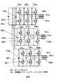
本第1の実施の形態では、三相交流モータなのでU、V、Wの三相交流を9つのステータコア101に対応させるので、U、V、Wの三相交流の各相をそれぞれ3つに分割するため、モータの各相ステータコイル204および、各相ステータコイル204を駆動する主駆動上下アームパワースイッチング素子300も各相に対して3つに分割され、9つのステータコア101と同数とするが、3分割分が並列接続されている。主駆動上下アームパワースイッチング素子300は入力される直流電圧値を最大とする矩形波状の出力電圧を生成するために、上下アームを構成しており、例えばIGBTを使用した場合には、逆並列に還流ダイオードが接続された、合計で4つのパワー素子から構成されている。図3に本第1の実施の形態に使用されるIGBTを使用したインバータのパワードライバの電気的等価回路を示している。各相のステータコイル204、主駆動上下アームパワースイッチング素子300が3つに分割され並列接続されている。例えばU相の主駆動上下アームパワースイッチング素子300はU1相、U2相、U3相の主駆動上下アームパワースイッチング素子300U1、300U2、300U3に分割され、U相のステータコイル204はU1相、U2相、U3相のステータコイル204U1、204U2、204U3に分割されている。U1相、U2相、U3相の主駆動上下アームパワースイッチング素子300(300U1、300U2、300U3)は全て同じ信号で駆動され、U1相、U2相、U3相のステータコイル204(204U1、204U2、204U3)には同位相で等しい値の電流が流れることになる。主駆動上下アームパワースイッチング素子300の内部には4つのパワー素子が配置されているが、熱的に不均一にならぬようできるだけ内部のパワー素子を近接して配置したり、良熱伝導性のヒートスプレッダ等を共通に使用することが望ましい。
【0012】
主駆動上下アームパワースイッチング素子300の入出力パワー端子としては、入力の直流電力端子が2つ、出力端子104が1つの計3つが設けられており、このうち2つの直流端子は平滑用コンデンサ400と配線107、108を用い、それぞれが短距離に接続されている。同時に配線107、108は、外部直流入力配線109と端子部106にて接続(107用外部直流端子部は図1の側面図には表現されていない)されている。一方各相の交流出力は出力端子104の接続端子部105に接続された配線部103を用い、直近で同相となるステータコイル204と短距離で接続されている。
【0013】
このように、従来は一部に集中してインバータが配置されていたのにくらべ、主駆動上下アームパワースイッチング素子300をステータの周囲に均等配置することにより、主駆動上下アームパワースイッチング素子300の出力をステータコイル204と同一線材で、しかも短い経路でステータコイル204に接続することが可能になるため、配線部103の製作コストおよび製造コストが低く抑えられる。
【0014】
また、従来はインバータとモータ間の電力配線をU、V、Wの三本で配線していたため、インバータ出力端子とモータ側入力端子との接続部位に大きな電流が流れ、この接続部位での損失をできるだけ抑えるためには、大型ボルト等で両者を締結せねばならなかった。
【0015】
しかし本第1の実施の形態では、ステータコイル204の数だけ主駆動上下アームパワースイッチング素子300を分割しているため、各ステータコイル204と各主駆動上下アームパワースイッチング素子300の出力の接続部に流れる電流は分割数分だけ小さくなり、接続部でのジュール発熱が小さくなるので接続が容易になる。具体的には、小型ボルトあるいはボルトを使わずにバネ状のおさえのみで接続したり、簡便な半田付けで接続することが可能になる。このように接続部の構造を簡便にすることによって、全体の小型化、製造コストの低減が可能となる。
【0016】
さらに、従来はステータ用冷却通路と、インバータ用冷却通路がそれぞれ独立に構成されていたか、あるいは共有していても、インバータをステータ用冷却通路の一部分に集中配置していたため、大部分の冷却通路はステータコイル204を冷却するためだけに使われており、冷却面を有効に使い切っていなかった。このため従来は、最適な冷却器を設計した場合、冷却器が大型化する問題があった。
【0017】
しかし図2の本第1の実施形態で示すように冷却通路102の第一の主冷却面102aの近傍にステータコイル204を配置し、第二の主冷却面102b近傍に主駆動上下アームパワースイッチング素子300を配置する構成としたため、各相のステータコイル204と主駆動上下アームパワースイッチング素子300が冷却通路102を互いに共有するため、冷却器がより小型化にでき、機電一体型駆動装置を小型化できるという効果がある。
【0018】
図4は、本発明の第2の実施の形態を示す機電一体型駆動装置の側面図であり、図5は図4のB−B断面図を示す。
【0019】
図5において各冷却通路102は各相のステータコイル204に対応して互いに独立して9つ形成されており、冷却通路102を共用するよう配置され、第一の主冷却面102a近傍に位置するステータコイル204と第二の主冷却面102b近傍に位置する主駆動上下アームパワースイッチング素子300は、電気的には異なった相となるように配線部103で接続される。つまりU1相の主駆動上下アームパワースイッチング素子300U1とV1相のステータコイル204V1が冷却通路102を共有している。
【0020】
一般にステータコイル204およびステータコア101の熱容量、あるいは主駆動上下アームパワースイッチング素子300に密着しているヒートスプレッダの熱容量が比較的大きいため、モータが回転している場合は、各相のステータコイル204や主駆動上下アームパワースイッチング素子300の損失が平均化され、ステータコイル204の損失は、鉄損や表皮効果を無視すれば、ステータコイル204を流れる電流の実効値の二乗に比例し、且つ全てのステータコイル204の損失は等しくなっている。一方図3に示す主駆動上下アームパワースイッチング素子300の損失も、上アームIGBTと下アームIGBTとは共に等しい損失となり、上アームダイオード、下アームダイオードも共に等しい損失となる。結果として9つ全ての主駆動上下アームパワースイッチング素子300の損失は全て等しく、同様に9つ全てのステータコイル204の損失も等しくなっている。
【0021】
しかしモータがロックしたり、あるいは熱時定数が無視出来るほど低い回転でモータがトルクを発生している場合には、各相の主駆動上下アームパワースイッチング素子300、及び各相のステータコイル204の損失は前述の様に均一ではなくなる。例えばU相コイルの電流が正の向きで最大値の時にロックした状態を考えると、U相コイルに流れる電流は、V相コイルとW相のコイルに流れる電流の和となる。主駆動上下アームパワースイッチング素子300に関しても同様である。従って、U相コイルの損失はV相コイルの損失あるいはW相コイルの損失より大きくなり、U相主駆動上下アームパワースイッチング素子300U1、300U2、300U3の損失はV相主駆動上下アームパワースイッチング素子300V1、300V2、300V3の損失あるいはW相主駆動上下アームパワースイッチング素子300W1、300W2、300W3の損失よりも大きくなる。しかも、一般に、ロック状態では前述のようにモータが回転し損失が平均化されている状態に比べ各部の損失自体が大きくなるので、U相ステータコイル204U1、204U2、204U3とU相主駆動上下アームパワースイッチング素子300U1、300U2、300U3が冷却通路102を共用すると、冷却器が大型化してしまうが、本第2の実施の形態では、異なった相のステータコイル204と主駆動上下アームパワースイッチング素子300(例えばV1相ステータコイル204V1とU1相主駆動上下アームパワースイッチング素子300U1)が冷却通路102を共用するため、冷却通路102の小型化が図れる。
この第2の実施の形態の様に、各相の冷却通路102を完全に独立に配置した方が冷却面が有効に使えるため冷却液体の流量を下げることができ、結果として冷却ポンプを含む全体冷却システムの小型化が可能となる。
また、本第2の実施の形態の様に冷却通路102を異なった相で共用するように隣接した主駆動上下アームパワースイッチング素子300とステータコイル204を接続する際でも、隣接した主駆動上下アームパワースイッチング素子300とステータコイル204をステータコイル204の巻線と同一の線材を用いて、短距離で接続できるため、第1の実施の形態と同様の効果も得られる。
【0022】
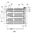
図6は、本発明の第3の実施の形態を示す機電一体インバータの断面図を示す。
【0023】
これまで述べた本発明の第1、第2の実施の形態はいわゆるインナーロータタイプのモータに関して説明したが、図6に断面図を示すアウターロータタイプの交流モータに関しても本発明は適用可能である。
【図面の簡単な説明】
【図1】本発明の第1の実施の形態の機電一体型駆動装置の側面図。
【図2】図1のA−A断面図。
【図3】本発明の第1の実施の形態のインバータの電気的等価回路。
【図4】本発明の第2の実施の形態の機電一体型駆動装置の側面図。
【図5】図4のB−B断面図。
【図6】本発明の第3の実施の形態の機電一体型駆動装置の断面図。
【符号の説明】
101 ステータコア
102 冷却通路
102a 第一の主冷却面
102b 第二の主冷却面
204 ステータコイル
300 主駆動上下アームパワースイッチング素子[0001]
TECHNICAL FIELD OF THE INVENTION
The present invention relates to an electromechanical integrated drive device in which an AC motor and an inverter are integrally mounted.
[0002]
[Prior art]
[Patent Document] JP-A-2000-166176.
As a conventional electromechanical integrated drive device in which an AC motor and an inverter are integrally mounted, the above-mentioned patent document has a structure in which the inverter is concentrated on the AC motor.
[0003]
[Problems to be solved by the invention]
Conventionally, since the inverter is concentrated on the upper part of the AC motor, the distance from the inverter output terminal to the motor winding is relatively long, the loss in the wiring part is large, and unnecessary radiation noise and unnecessary conduction noise are easily generated. There was a problem.
[0004]
The present invention has been made in order to solve the above-described problems, and has as its object to provide an electromechanical integrated drive device capable of suppressing generation of radiation or conduction noise due to a rapid change in current.
[0005]
[Means for Solving the Problems]
According to the present invention, the power driver for outputting each AC phase of the inverter that drives the AC motor is arranged around the stator of the AC motor.
[0006]
【The invention's effect】
ADVANTAGE OF THE INVENTION According to this invention, unnecessary radiation noise and unnecessary conduction noise accompanying the supply of AC output from an inverter to an AC motor can be reduced, and wiring loss can also be reduced.
[0007]
BEST MODE FOR CARRYING OUT THE INVENTION
Hereinafter, embodiments of the present invention will be described with reference to the drawings. In the drawings described below, components having the same function are denoted by the same reference numerals, and repeated description thereof will be omitted.
[0008]
FIG. 1 is a side view of an electromechanical integrated driving device according to a first embodiment of the present invention, and FIG. 2 is a cross-sectional view taken along line AA of FIG. The three-phase AC motor according to the present embodiment is an example of a so-called concentrated winding embedded magnet motor in which coils of each phase are concentratedly wound around a stator core of each phase.
[0009]
110 is a rotor, 203 is a motor rotation shaft attached to the
[0010]
A
[0011]
In the first embodiment, since the three-phase AC motor is a three-phase AC motor, three phases of U, V, and W are made to correspond to the nine
[0012]
As the input / output power terminals of the main drive upper / lower arm
[0013]
As described above, by arranging the main drive upper and lower arm
[0014]
Conventionally, the power wiring between the inverter and the motor is wired with three wires of U, V, and W. Therefore, a large current flows in a connection portion between the inverter output terminal and the motor-side input terminal, and a loss at the connection portion. In order to minimize the noise, the two had to be fastened with a large bolt or the like.
[0015]
However, in the first embodiment, since the main drive upper and lower arm
[0016]
Further, even though the cooling passage for the stator and the cooling passage for the inverter are conventionally independently configured or shared, the cooling passage for most of the cooling passage is arranged because the inverter is concentrated in a part of the cooling passage for the stator. Are used only for cooling the
[0017]
However, as shown in the first embodiment of FIG. 2, the
[0018]
FIG. 4 is a side view of an electromechanical integrated driving device according to a second embodiment of the present invention, and FIG. 5 is a sectional view taken along line BB of FIG.
[0019]
In FIG. 5, nine cooling
[0020]
Generally, since the heat capacity of the
[0021]
However, when the motor is locked or the motor is generating torque at a rotation at which the thermal time constant is negligibly low, the main drive upper and lower arm
As in the second embodiment, when the
Further, even when the adjacent main drive upper and lower arm
[0022]
FIG. 6 is a sectional view of a mechanical and electric integrated inverter showing a third embodiment of the present invention.
[0023]
Although the first and second embodiments of the present invention described so far have been described with respect to a so-called inner rotor type motor, the present invention is also applicable to an outer rotor type AC motor whose sectional view is shown in FIG. .
[Brief description of the drawings]
FIG. 1 is a side view of an electromechanical integrated drive device according to a first embodiment of the present invention.
FIG. 2 is a sectional view taken along line AA of FIG.
FIG. 3 is an electrical equivalent circuit of the inverter according to the first embodiment of the present invention.
FIG. 4 is a side view of an electromechanical integrated drive device according to a second embodiment of the present invention.
FIG. 5 is a sectional view taken along line BB of FIG. 4;
FIG. 6 is a cross-sectional view of an electromechanical integrated drive device according to a third embodiment of the present invention.
[Explanation of symbols]
101
Claims (5)
前記インバータの前記交流出力によって回転駆動される交流モータとを備えた機電一体型駆動装置において、
前記インバータの前記交流出力の各相の前記交流出力を出力するパワードライバを前記交流モータのステータの周囲に配置し、前記パワードライバは、前記ステータコア数と同じ数に分割され、分割された前記パワードライバの前記各相の前記交流出力の出力端子を直近で同相となるステータコイルに接続する
、ことを特徴とする機電一体型駆動装置。An inverter for converting the DC output of the DC power supply to an AC output;
An electromechanical integrated drive device comprising: an AC motor that is rotationally driven by the AC output of the inverter.
A power driver that outputs the AC output of each phase of the AC output of the inverter is arranged around a stator of the AC motor, and the power driver is divided into the same number as the number of stator cores, and the divided power is An electromechanical integrated drive device , wherein an output terminal of the AC output of each of the phases of the driver is connected to a stator coil which is in phase in the closest vicinity .
前記インバータの前記交流出力によって回転駆動される交流モータとを備えた機電一体型駆動装置において、
前記インバータの前記交流出力の各相の前記交流出力を出力するパワードライバを前記交流モータのステータの周囲に配置し、前記パワードライバは、前記ステータコア数と同じ数に分割され、前記ステータの周囲近傍に少なくとも2つの対向する第一、第二の主冷却面を持つ冷却通路を設け、前記第一の主冷却面近傍に前記ステータコイルを配置し、対向する前記第二の主冷却面近傍に前記パワードライバを配置し、前記第一の主冷却面近傍に配置された前記ステータコイルを駆動する前記交流出力の相と、対向する第二の主冷却面近傍に配置された前記パワードライバが出力する前記交流出力の相が異なることを特徴とする機電一体型駆動装置。 An inverter for converting the DC output of the DC power supply to an AC output;
An electromechanical integrated drive device comprising: an AC motor that is rotationally driven by the AC output of the inverter.
A power driver that outputs the AC output of each phase of the AC output of the inverter is arranged around the stator of the AC motor, and the power driver is divided into the same number as the number of the stator cores, and the vicinity of the periphery of the stator. A cooling passage having at least two opposing first and second main cooling surfaces is provided, the stator coil is disposed near the first main cooling surface, and the cooling passage is disposed near the opposing second main cooling surface. A power driver is arranged, and the AC output phase for driving the stator coil arranged near the first main cooling surface and the power driver arranged near the opposing second main cooling surface output. The electromechanical integrated driving device, wherein the phases of the AC output are different.
Priority Applications (4)
| Application Number | Priority Date | Filing Date | Title |
|---|---|---|---|
| JP2002323780A JP3559909B2 (en) | 2002-11-07 | 2002-11-07 | Electromechanical drive |
| US10/692,854 US6930417B2 (en) | 2002-11-07 | 2003-10-27 | A.C. motor-inverter integrated drive unit |
| EP03025677A EP1418660B1 (en) | 2002-11-07 | 2003-11-07 | A.C. Motor-inverter integrated drive unit |
| DE60313933T DE60313933T2 (en) | 2002-11-07 | 2003-11-07 | Drive unit with A.C. Motor and integrated inverter |
Applications Claiming Priority (1)
| Application Number | Priority Date | Filing Date | Title |
|---|---|---|---|
| JP2002323780A JP3559909B2 (en) | 2002-11-07 | 2002-11-07 | Electromechanical drive |
Publications (2)
| Publication Number | Publication Date |
|---|---|
| JP2004159454A JP2004159454A (en) | 2004-06-03 |
| JP3559909B2 true JP3559909B2 (en) | 2004-09-02 |
Family
ID=32105475
Family Applications (1)
| Application Number | Title | Priority Date | Filing Date |
|---|---|---|---|
| JP2002323780A Expired - Fee Related JP3559909B2 (en) | 2002-11-07 | 2002-11-07 | Electromechanical drive |
Country Status (4)
| Country | Link |
|---|---|
| US (1) | US6930417B2 (en) |
| EP (1) | EP1418660B1 (en) |
| JP (1) | JP3559909B2 (en) |
| DE (1) | DE60313933T2 (en) |
Cited By (1)
| Publication number | Priority date | Publication date | Assignee | Title |
|---|---|---|---|---|
| JP2008099401A (en) * | 2006-10-10 | 2008-04-24 | Nissan Motor Co Ltd | Power conversion device |
Families Citing this family (70)
| Publication number | Priority date | Publication date | Assignee | Title |
|---|---|---|---|---|
| US6927524B2 (en) * | 2001-11-27 | 2005-08-09 | Wavecrest Laboratories, Llc | Rotary electric motor having separate control modules for respective stator electromagnets |
| JP4156542B2 (en) * | 2004-03-03 | 2008-09-24 | 三菱電機株式会社 | Rotating electrical machine for vehicle |
| DE102004048908A1 (en) * | 2004-10-06 | 2006-04-20 | Daimlerchrysler Ag | Powertrain for a vehicle with electric machine |
| CN100581048C (en) | 2005-03-31 | 2010-01-13 | 阿尔斯通技术有限公司 | High-phase order generator |
| DE102005026779A1 (en) * | 2005-06-10 | 2006-12-28 | Bayerische Motoren Werke Ag | Electric drive device |
| DE102005032191A1 (en) * | 2005-07-09 | 2007-02-08 | Zf Friedrichshafen Ag | Electric machine with integrated power electronics and method for producing the contacting of the DC rails with the DC contact surfaces of the power semiconductors of the power electronics |
| US7733674B2 (en) | 2006-11-22 | 2010-06-08 | Nissan Motor Co., Ltd. | Power conversion apparatus for converting direct current to polyphase alternating current |
| JP4987495B2 (en) * | 2007-01-25 | 2012-07-25 | 株式会社東芝 | Motor drive system for rail car drive |
| JP5332753B2 (en) * | 2009-03-10 | 2013-11-06 | 日産自動車株式会社 | Mechanical and electric integrated drive |
| JP5327646B2 (en) | 2009-06-24 | 2013-10-30 | 株式会社デンソー | Motor with built-in electronic circuit |
| JP5516066B2 (en) | 2009-06-24 | 2014-06-11 | 株式会社デンソー | Drive device |
| JP5435285B2 (en) | 2009-06-24 | 2014-03-05 | 株式会社デンソー | Drive device |
| JP5446937B2 (en) | 2009-06-24 | 2014-03-19 | 株式会社デンソー | Motor with built-in electronic circuit |
| JP5435284B2 (en) | 2009-06-24 | 2014-03-05 | 株式会社デンソー | Drive device |
| JP4957815B2 (en) | 2009-06-24 | 2012-06-20 | 株式会社デンソー | Semiconductor module and motor with built-in electronic circuit using the same |
| DE102010017522A1 (en) | 2009-06-24 | 2011-02-03 | ASMO Co., Ltd., Kosai-city | Drive device and semiconductor module |
| JP5435286B2 (en) | 2009-06-24 | 2014-03-05 | 株式会社デンソー | Drive device |
| JP5624330B2 (en) * | 2009-06-24 | 2014-11-12 | 株式会社デンソー | motor |
| JP5365872B2 (en) * | 2009-06-24 | 2013-12-11 | 株式会社デンソー | Drive device |
| JP5410194B2 (en) | 2009-08-07 | 2014-02-05 | 株式会社デンソー | Motor with built-in drive circuit |
| JP5370928B2 (en) * | 2010-01-14 | 2013-12-18 | 株式会社安川電機 | Motor and vehicle including the same |
| JP5201171B2 (en) | 2010-05-21 | 2013-06-05 | 株式会社デンソー | Semiconductor module and driving device using the same |
| JP5067679B2 (en) | 2010-05-21 | 2012-11-07 | 株式会社デンソー | Semiconductor module and driving device using the same |
| FI122756B (en) * | 2010-05-25 | 2012-06-29 | Abb Oy | Winding in an AC machine |
| JP2012044797A (en) * | 2010-08-20 | 2012-03-01 | Nissan Motor Co Ltd | Multi-phase rotary electric machine |
| KR101418291B1 (en) | 2011-04-27 | 2014-07-11 | 엘지전자 주식회사 | Electric motor and electric vechile having the same |
| JP2013198366A (en) * | 2012-03-22 | 2013-09-30 | Aisin Seiki Co Ltd | Inverter device |
| JP2013243337A (en) * | 2012-04-25 | 2013-12-05 | Jtekt Corp | Controller and motor unit including the same |
| GB201216099D0 (en) * | 2012-09-10 | 2012-10-24 | Protean Electric Ltd | Capacitor |
| DE102013210559A1 (en) * | 2013-06-06 | 2014-12-11 | Magna Powertrain Ag & Co. Kg | Motor / generator unit |
| DE102014205930A1 (en) * | 2014-03-31 | 2015-10-01 | Continental Automotive Gmbh | Electric machine |
| DE112015002343B4 (en) * | 2014-05-20 | 2022-06-09 | Mitsubishi Electric Corp. | Inverter integrated motor device |
| US10177633B2 (en) | 2014-12-23 | 2019-01-08 | Abb Schweiz Ag | Multiphase fractional slot concentrated winding machine with end mounted detachable or integrated multiphase series converter circuit |
| JP6485229B2 (en) * | 2015-06-03 | 2019-03-20 | 日産自動車株式会社 | Electric drive |
| DE102015219867A1 (en) * | 2015-10-13 | 2017-04-13 | Lenze Drives Gmbh | Circuit board, B-end shield, engine kit and electric motor |
| DE102015013403A1 (en) * | 2015-10-19 | 2017-04-20 | Bergische Universität Wuppertal | Electric drive system |
| DE102016209602A1 (en) * | 2016-06-01 | 2017-12-07 | Siemens Aktiengesellschaft | Electric machine |
| US10903776B2 (en) | 2017-05-31 | 2021-01-26 | Abb Schweiz Ag | Industrial electrical machine |
| EP3631952B1 (en) * | 2017-06-01 | 2021-12-01 | Mahle International GmbH | Electric machine with integrated power electronics |
| DE102017112993A1 (en) * | 2017-06-13 | 2018-12-13 | Volkswagen Aktiengesellschaft | Electric machine with integrated power electronics |
| US11843334B2 (en) | 2017-07-13 | 2023-12-12 | Denso Corporation | Rotating electrical machine |
| JP6665893B2 (en) * | 2017-07-21 | 2020-03-13 | 株式会社デンソー | Rotating electric machine |
| JP6977556B2 (en) | 2017-07-21 | 2021-12-08 | 株式会社デンソー | Rotating machine |
| CN113991958A (en) | 2017-07-21 | 2022-01-28 | 株式会社电装 | Rotating electrical machine |
| US10700571B2 (en) | 2017-12-08 | 2020-06-30 | Toyota Motor Engineering & Manufacturing North America, Inc. | Cooling system for vehicle motor drive |
| FR3075562B1 (en) | 2017-12-18 | 2019-12-20 | IFP Energies Nouvelles | CIRCULAR OR TOROIDAL POWER ELECTRONICS COOLED BY A FLOW |
| FR3075563B1 (en) | 2017-12-18 | 2023-09-01 | Ifp Energies Now | FLOW-COOLED POWER ELECTRONICS |
| JP6927186B2 (en) | 2017-12-28 | 2021-08-25 | 株式会社デンソー | Rotating machine |
| JP7006541B2 (en) | 2017-12-28 | 2022-01-24 | 株式会社デンソー | Rotating machine |
| DE112018006651T5 (en) | 2017-12-28 | 2020-10-08 | Denso Corporation | Wheel drive device |
| CN111566904B (en) | 2017-12-28 | 2023-04-28 | 株式会社电装 | Rotary electric machine |
| DE112018006699T5 (en) | 2017-12-28 | 2020-09-10 | Denso Corporation | Rotating electric machine |
| DE102018201206A1 (en) * | 2018-01-26 | 2019-08-01 | Siemens Aktiengesellschaft | Modular arrangement of an inverter and aircraft with such an arrangement |
| JP6977682B2 (en) * | 2018-07-25 | 2021-12-08 | 株式会社デンソー | Rotating electric machine unit |
| JP7251340B2 (en) | 2018-07-25 | 2023-04-04 | 株式会社デンソー | Armature winding manufacturing method |
| WO2020022366A1 (en) * | 2018-07-25 | 2020-01-30 | 株式会社デンソー | Dynamo-electric machine and wheel using said dynamo-electric machine |
| US10862371B2 (en) | 2018-12-14 | 2020-12-08 | Bendix Commercial Vehicle Systems Llc | Perimeter liquid-cooled electric machine and integrated power inverter |
| US10807730B2 (en) | 2018-12-21 | 2020-10-20 | General Electric Company | Motor driven propulsor of an aircraft |
| JP7205351B2 (en) * | 2019-03-29 | 2023-01-17 | 株式会社デンソー | Rotating electric machine and manufacturing method of rotating electric machine |
| MX2021013088A (en) | 2019-04-25 | 2021-11-17 | American Axle & Mfg Inc | Electric drive module. |
| DE102020200657A1 (en) * | 2019-12-06 | 2021-06-10 | Brose Fahrzeugteile SE & Co. Kommanditgesellschaft, Würzburg | Fluid-cooled electrical machine |
| FR3105892B1 (en) * | 2019-12-31 | 2023-07-14 | Thales Sa | COOLING DEVICE AND MOTOR-VARIATOR |
| GB2592574A (en) * | 2020-02-19 | 2021-09-08 | Safran Electrical & Power | A modular stator arrangement |
| US11605949B2 (en) | 2020-07-20 | 2023-03-14 | Abb Schweiz Ag | Electrification arrangement for supplying power to electrical loads |
| DE102020120117A1 (en) | 2020-07-30 | 2022-02-03 | Schaeffler Technologies AG & Co. KG | Stator with winding structures for modular e-machines |
| EP4309274A1 (en) | 2021-03-15 | 2024-01-24 | American Axle & Manufacturing, Inc. | Electric drive unit |
| US11668323B2 (en) * | 2021-06-28 | 2023-06-06 | Garrett Transportation I Inc. | Coolant system for integrated e-machine controller for turbomachine |
| FR3126591B1 (en) | 2021-08-31 | 2023-07-14 | Safran Electrical & Power | DC VOLTAGE FILTER FOR AN INVERTER INPUT OF AN ELECTRIC AIRCRAFT PROPULSION MACHINE |
| WO2023101925A1 (en) | 2021-12-01 | 2023-06-08 | American Axle & Manufacturing, Inc. | Electric drive unit with motor assembly isolated from beaming loads transmitted through housing assembly |
| US11942825B2 (en) * | 2022-01-12 | 2024-03-26 | Dana Automotive Systems Group, Llc | Cooling system for an electric machine |
Family Cites Families (10)
| Publication number | Priority date | Publication date | Assignee | Title |
|---|---|---|---|---|
| AU528610B2 (en) * | 1978-05-10 | 1983-05-05 | Commonwealth Of Australia, The | Inductor alternator |
| US5491370A (en) * | 1994-01-28 | 1996-02-13 | General Motors Corporation | Integrated AC machine |
| GB2293694B (en) * | 1994-09-30 | 1998-03-18 | Aisin Seiki | Switched reluctance motor |
| EP0823771B1 (en) * | 1996-02-23 | 2006-04-26 | Matsushita Electric Industrial Co., Ltd. | Motor |
| JPH10234158A (en) * | 1997-02-19 | 1998-09-02 | Tokyo R & D:Kk | Motor |
| JPH10322973A (en) * | 1997-05-14 | 1998-12-04 | Toshiba Corp | Motor mounted with power converter |
| JP2000166176A (en) | 1998-12-01 | 2000-06-16 | Hitachi Ltd | Cooling mechanism of mechanically/electrically integrated drive unit |
| JP3661589B2 (en) * | 2000-11-21 | 2005-06-15 | 日産自動車株式会社 | Motor or generator |
| DE10112799C1 (en) | 2001-03-16 | 2002-10-17 | Compact Dynamics Gmbh | Fluid cooled electrical machine |
| EP1401089A1 (en) * | 2002-09-18 | 2004-03-24 | Continental ISAD Electronic Systems GmbH & Co. KG | Electrical machine, formed as starter, generator or starter-generator for a vehicle |
-
2002
- 2002-11-07 JP JP2002323780A patent/JP3559909B2/en not_active Expired - Fee Related
-
2003
- 2003-10-27 US US10/692,854 patent/US6930417B2/en not_active Expired - Lifetime
- 2003-11-07 DE DE60313933T patent/DE60313933T2/en not_active Expired - Lifetime
- 2003-11-07 EP EP03025677A patent/EP1418660B1/en not_active Expired - Fee Related
Cited By (1)
| Publication number | Priority date | Publication date | Assignee | Title |
|---|---|---|---|---|
| JP2008099401A (en) * | 2006-10-10 | 2008-04-24 | Nissan Motor Co Ltd | Power conversion device |
Also Published As
| Publication number | Publication date |
|---|---|
| US20040090130A1 (en) | 2004-05-13 |
| US6930417B2 (en) | 2005-08-16 |
| EP1418660B1 (en) | 2007-05-23 |
| EP1418660A1 (en) | 2004-05-12 |
| DE60313933T2 (en) | 2007-09-06 |
| JP2004159454A (en) | 2004-06-03 |
| DE60313933D1 (en) | 2007-07-05 |
Similar Documents
| Publication | Publication Date | Title |
|---|---|---|
| JP3559909B2 (en) | Electromechanical drive | |
| JP4625147B2 (en) | Synchronous motor drive system | |
| US8110954B2 (en) | Electric rotating machine | |
| US9539909B2 (en) | Inverter-integrated driving module and manufacturing method therefor | |
| JP6389877B2 (en) | Inverter for electric motor or generator | |
| JP5624330B2 (en) | motor | |
| JPH10322973A (en) | Motor mounted with power converter | |
| EP2763287B1 (en) | Main electric motor for railway vehicle | |
| JP2017017975A (en) | Electric compressor | |
| US11641173B2 (en) | Control apparatus of rotary electric machine and method therefor | |
| JP4045923B2 (en) | Electric motor | |
| GB2574018A (en) | A lead frame for an electric motor or generator | |
| JP6515836B2 (en) | Inverter device | |
| US20210135527A1 (en) | A lead frame for an electric motor or generator | |
| JP3972855B2 (en) | Inverter module | |
| JP2004096940A (en) | Permanent magnet type synchronous motor | |
| JP5696438B2 (en) | Permanent magnet type motor | |
| JP6565756B2 (en) | Rotating electric machine drive system | |
| CN211046585U (en) | Structure for cooling lead frame and winding coil and generator or motor | |
| CN211046602U (en) | Connecting structure of lead frame and winding coil | |
| TWI644507B (en) | Hybrid dc and switched reluctance motor module | |
| JP4222814B2 (en) | Brushless DC motor drive device | |
| JP2008283062A (en) | Module structure of semiconductor element | |
| JP2001037136A (en) | Lead wire structure of rotary electrical apparatus |
Legal Events
| Date | Code | Title | Description |
|---|---|---|---|
| A521 | Written amendment |
Free format text: JAPANESE INTERMEDIATE CODE: A523 Effective date: 20040331 |
|
| TRDD | Decision of grant or rejection written | ||
| A01 | Written decision to grant a patent or to grant a registration (utility model) |
Free format text: JAPANESE INTERMEDIATE CODE: A01 Effective date: 20040427 |
|
| A61 | First payment of annual fees (during grant procedure) |
Free format text: JAPANESE INTERMEDIATE CODE: A61 Effective date: 20040510 |
|
| R150 | Certificate of patent or registration of utility model |
Ref document number: 3559909 Country of ref document: JP Free format text: JAPANESE INTERMEDIATE CODE: R150 Free format text: JAPANESE INTERMEDIATE CODE: R150 |
|
| FPAY | Renewal fee payment (event date is renewal date of database) |
Free format text: PAYMENT UNTIL: 20080604 Year of fee payment: 4 |
|
| FPAY | Renewal fee payment (event date is renewal date of database) |
Free format text: PAYMENT UNTIL: 20090604 Year of fee payment: 5 |
|
| FPAY | Renewal fee payment (event date is renewal date of database) |
Free format text: PAYMENT UNTIL: 20090604 Year of fee payment: 5 |
|
| FPAY | Renewal fee payment (event date is renewal date of database) |
Free format text: PAYMENT UNTIL: 20100604 Year of fee payment: 6 |
|
| R250 | Receipt of annual fees |
Free format text: JAPANESE INTERMEDIATE CODE: R250 |
|
| FPAY | Renewal fee payment (event date is renewal date of database) |
Free format text: PAYMENT UNTIL: 20110604 Year of fee payment: 7 |
|
| FPAY | Renewal fee payment (event date is renewal date of database) |
Free format text: PAYMENT UNTIL: 20120604 Year of fee payment: 8 |
|
| FPAY | Renewal fee payment (event date is renewal date of database) |
Free format text: PAYMENT UNTIL: 20120604 Year of fee payment: 8 |
|
| FPAY | Renewal fee payment (event date is renewal date of database) |
Free format text: PAYMENT UNTIL: 20130604 Year of fee payment: 9 |
|
| LAPS | Cancellation because of no payment of annual fees |