EP3364220A1 - Verfahren und system zur erweiterung der tiefenschärfe - Google Patents
Verfahren und system zur erweiterung der tiefenschärfe Download PDFInfo
- Publication number
- EP3364220A1 EP3364220A1 EP17202513.2A EP17202513A EP3364220A1 EP 3364220 A1 EP3364220 A1 EP 3364220A1 EP 17202513 A EP17202513 A EP 17202513A EP 3364220 A1 EP3364220 A1 EP 3364220A1
- Authority
- EP
- European Patent Office
- Prior art keywords
- lens
- optical element
- arrangement
- imaging
- phase
- Prior art date
- Legal status (The legal status is an assumption and is not a legal conclusion. Google has not performed a legal analysis and makes no representation as to the accuracy of the status listed.)
- Granted
Links
- 238000000034 method Methods 0.000 title description 54
- 230000003287 optical effect Effects 0.000 claims abstract description 259
- 238000003384 imaging method Methods 0.000 claims abstract description 235
- 230000007704 transition Effects 0.000 claims abstract description 93
- 239000000463 material Substances 0.000 claims description 19
- 238000003780 insertion Methods 0.000 claims description 3
- 230000037431 insertion Effects 0.000 claims description 3
- 230000004438 eyesight Effects 0.000 description 46
- 238000012937 correction Methods 0.000 description 32
- 230000006870 function Effects 0.000 description 32
- 238000012546 transfer Methods 0.000 description 24
- 238000013459 approach Methods 0.000 description 14
- 230000004075 alteration Effects 0.000 description 11
- 210000004087 cornea Anatomy 0.000 description 10
- 239000011521 glass Substances 0.000 description 10
- 210000001747 pupil Anatomy 0.000 description 10
- 238000013461 design Methods 0.000 description 8
- 230000000694 effects Effects 0.000 description 8
- 238000005286 illumination Methods 0.000 description 8
- 230000035945 sensitivity Effects 0.000 description 8
- 230000001427 coherent effect Effects 0.000 description 7
- 208000001491 myopia Diseases 0.000 description 7
- 238000012545 processing Methods 0.000 description 7
- 230000010076 replication Effects 0.000 description 7
- 210000001525 retina Anatomy 0.000 description 7
- 230000003247 decreasing effect Effects 0.000 description 5
- 238000009826 distribution Methods 0.000 description 5
- 238000012805 post-processing Methods 0.000 description 5
- 238000004088 simulation Methods 0.000 description 5
- 230000005540 biological transmission Effects 0.000 description 4
- 238000005520 cutting process Methods 0.000 description 4
- 238000002513 implantation Methods 0.000 description 4
- 238000004519 manufacturing process Methods 0.000 description 4
- 230000000737 periodic effect Effects 0.000 description 4
- 239000002131 composite material Substances 0.000 description 3
- 230000006872 improvement Effects 0.000 description 3
- 238000010348 incorporation Methods 0.000 description 3
- 230000000051 modifying effect Effects 0.000 description 3
- 238000000059 patterning Methods 0.000 description 3
- 201000010041 presbyopia Diseases 0.000 description 3
- 230000008569 process Effects 0.000 description 3
- 230000000750 progressive effect Effects 0.000 description 3
- 230000001902 propagating effect Effects 0.000 description 3
- 230000009467 reduction Effects 0.000 description 3
- 208000002177 Cataract Diseases 0.000 description 2
- 238000002679 ablation Methods 0.000 description 2
- 238000000149 argon plasma sintering Methods 0.000 description 2
- 210000004556 brain Anatomy 0.000 description 2
- 239000000969 carrier Substances 0.000 description 2
- 230000007423 decrease Effects 0.000 description 2
- 238000009792 diffusion process Methods 0.000 description 2
- 238000001839 endoscopy Methods 0.000 description 2
- 238000002430 laser surgery Methods 0.000 description 2
- 238000005259 measurement Methods 0.000 description 2
- 238000005457 optimization Methods 0.000 description 2
- 238000006116 polymerization reaction Methods 0.000 description 2
- 230000005855 radiation Effects 0.000 description 2
- 238000012216 screening Methods 0.000 description 2
- 238000001356 surgical procedure Methods 0.000 description 2
- 238000012795 verification Methods 0.000 description 2
- 102000008186 Collagen Human genes 0.000 description 1
- 108010035532 Collagen Proteins 0.000 description 1
- 201000002287 Keratoconus Diseases 0.000 description 1
- 230000006978 adaptation Effects 0.000 description 1
- 208000008303 aniridia Diseases 0.000 description 1
- ISQINHMJILFLAQ-UHFFFAOYSA-N argon hydrofluoride Chemical compound F.[Ar] ISQINHMJILFLAQ-UHFFFAOYSA-N 0.000 description 1
- 238000003491 array Methods 0.000 description 1
- 238000000429 assembly Methods 0.000 description 1
- 230000000712 assembly Effects 0.000 description 1
- 230000004888 barrier function Effects 0.000 description 1
- 230000008901 benefit Effects 0.000 description 1
- 230000003139 buffering effect Effects 0.000 description 1
- 230000001413 cellular effect Effects 0.000 description 1
- 230000008859 change Effects 0.000 description 1
- 229920001436 collagen Polymers 0.000 description 1
- 239000003086 colorant Substances 0.000 description 1
- 238000004891 communication Methods 0.000 description 1
- 239000012141 concentrate Substances 0.000 description 1
- 230000001054 cortical effect Effects 0.000 description 1
- 238000006073 displacement reaction Methods 0.000 description 1
- 238000005553 drilling Methods 0.000 description 1
- 238000005516 engineering process Methods 0.000 description 1
- 238000005530 etching Methods 0.000 description 1
- 239000012530 fluid Substances 0.000 description 1
- 238000009472 formulation Methods 0.000 description 1
- 239000007789 gas Substances 0.000 description 1
- 238000000227 grinding Methods 0.000 description 1
- 239000007943 implant Substances 0.000 description 1
- 238000007689 inspection Methods 0.000 description 1
- 230000031700 light absorption Effects 0.000 description 1
- 239000007788 liquid Substances 0.000 description 1
- 238000007620 mathematical function Methods 0.000 description 1
- 238000002558 medical inspection Methods 0.000 description 1
- 239000000203 mixture Substances 0.000 description 1
- 238000012986 modification Methods 0.000 description 1
- 230000004048 modification Effects 0.000 description 1
- 230000004379 myopia Effects 0.000 description 1
- 230000005693 optoelectronics Effects 0.000 description 1
- 210000000056 organ Anatomy 0.000 description 1
- 239000002245 particle Substances 0.000 description 1
- 230000000149 penetrating effect Effects 0.000 description 1
- 230000001179 pupillary effect Effects 0.000 description 1
- 238000011084 recovery Methods 0.000 description 1
- 230000037390 scarring Effects 0.000 description 1
- 238000007493 shaping process Methods 0.000 description 1
- 230000003068 static effect Effects 0.000 description 1
- 238000003325 tomography Methods 0.000 description 1
- 238000002834 transmittance Methods 0.000 description 1
- 239000012780 transparent material Substances 0.000 description 1
- XLYOFNOQVPJJNP-UHFFFAOYSA-N water Substances O XLYOFNOQVPJJNP-UHFFFAOYSA-N 0.000 description 1
Images


Classifications
-
- G—PHYSICS
- G02—OPTICS
- G02B—OPTICAL ELEMENTS, SYSTEMS OR APPARATUS
- G02B27/00—Optical systems or apparatus not provided for by any of the groups G02B1/00 - G02B26/00, G02B30/00
-
- G—PHYSICS
- G02—OPTICS
- G02B—OPTICAL ELEMENTS, SYSTEMS OR APPARATUS
- G02B27/00—Optical systems or apparatus not provided for by any of the groups G02B1/00 - G02B26/00, G02B30/00
- G02B27/42—Diffraction optics, i.e. systems including a diffractive element being designed for providing a diffractive effect
- G02B27/46—Systems using spatial filters
-
- A—HUMAN NECESSITIES
- A61—MEDICAL OR VETERINARY SCIENCE; HYGIENE
- A61F—FILTERS IMPLANTABLE INTO BLOOD VESSELS; PROSTHESES; DEVICES PROVIDING PATENCY TO, OR PREVENTING COLLAPSING OF, TUBULAR STRUCTURES OF THE BODY, e.g. STENTS; ORTHOPAEDIC, NURSING OR CONTRACEPTIVE DEVICES; FOMENTATION; TREATMENT OR PROTECTION OF EYES OR EARS; BANDAGES, DRESSINGS OR ABSORBENT PADS; FIRST-AID KITS
- A61F2/00—Filters implantable into blood vessels; Prostheses, i.e. artificial substitutes or replacements for parts of the body; Appliances for connecting them with the body; Devices providing patency to, or preventing collapsing of, tubular structures of the body, e.g. stents
- A61F2/02—Prostheses implantable into the body
- A61F2/14—Eye parts, e.g. lenses, corneal implants; Implanting instruments specially adapted therefor; Artificial eyes
- A61F2/16—Intraocular lenses
-
- G—PHYSICS
- G02—OPTICS
- G02B—OPTICAL ELEMENTS, SYSTEMS OR APPARATUS
- G02B27/00—Optical systems or apparatus not provided for by any of the groups G02B1/00 - G02B26/00, G02B30/00
- G02B27/0075—Optical systems or apparatus not provided for by any of the groups G02B1/00 - G02B26/00, G02B30/00 with means for altering, e.g. increasing, the depth of field or depth of focus
-
- G—PHYSICS
- G02—OPTICS
- G02B—OPTICAL ELEMENTS, SYSTEMS OR APPARATUS
- G02B27/00—Optical systems or apparatus not provided for by any of the groups G02B1/00 - G02B26/00, G02B30/00
- G02B27/42—Diffraction optics, i.e. systems including a diffractive element being designed for providing a diffractive effect
-
- G—PHYSICS
- G02—OPTICS
- G02B—OPTICAL ELEMENTS, SYSTEMS OR APPARATUS
- G02B27/00—Optical systems or apparatus not provided for by any of the groups G02B1/00 - G02B26/00, G02B30/00
- G02B27/58—Optics for apodization or superresolution; Optical synthetic aperture systems
-
- G—PHYSICS
- G02—OPTICS
- G02B—OPTICAL ELEMENTS, SYSTEMS OR APPARATUS
- G02B3/00—Simple or compound lenses
- G02B3/02—Simple or compound lenses with non-spherical faces
- G02B3/08—Simple or compound lenses with non-spherical faces with discontinuous faces, e.g. Fresnel lens
-
- G—PHYSICS
- G02—OPTICS
- G02B—OPTICAL ELEMENTS, SYSTEMS OR APPARATUS
- G02B3/00—Simple or compound lenses
- G02B3/10—Bifocal lenses; Multifocal lenses
-
- G—PHYSICS
- G02—OPTICS
- G02C—SPECTACLES; SUNGLASSES OR GOGGLES INSOFAR AS THEY HAVE THE SAME FEATURES AS SPECTACLES; CONTACT LENSES
- G02C7/00—Optical parts
- G02C7/02—Lenses; Lens systems ; Methods of designing lenses
- G02C7/06—Lenses; Lens systems ; Methods of designing lenses bifocal; multifocal ; progressive
-
- G—PHYSICS
- G02—OPTICS
- G02B—OPTICAL ELEMENTS, SYSTEMS OR APPARATUS
- G02B2207/00—Coding scheme for general features or characteristics of optical elements and systems of subclass G02B, but not including elements and systems which would be classified in G02B6/00 and subgroups
- G02B2207/129—Coded aperture imaging
Definitions
- This invention is generally in the field of imaging systems, and relates to an imaging lens arrangement with increased depth of focus.
- Extending the depth of focus of imaging systems is a very important core technology allowing its incorporation into various applications, including inter alia medically related applications where elements, such as cameras, are to be inserted into the body in order to observe and detect problematic tissues; as well as ophthalmic industry including glasses for spectacles, contact lenses, intraocular lenses or other lenses inserted surgically into the eye.
- the extended depth of focus solution is also needed for optical devices like microscopes or cameras for industrial, medical, surveillance or consumer applications, where focusing of light is required and where today focusing is being implemented by a multitude of lenses with the need of relative displacement between the focusing arrangement and an image and/or object plane, by mechanical movement, either manually or electronically driven.
- WO 03/076984 This technique provides an all-optical extended depth of field imaging.
- An imaging system produces images of acceptable quality of objects which are located at a wide variety of distances from the imaging system.
- a preferred embodiment of the imaging system includes an object, an auxiliary lens, a composite phase mask and a sensor arranged along an optical axis. Light from the object is focused by the auxiliary lens in tandem with the composite phase mask, producing an image which is incident on the detector.
- This technique is based upon placing a spatially highly resolved phase element on top of the lens aperture such that continuous set of focal length is generated.
- the present invention solves the above problems by providing an imaging arrangement utilizing an optical element located adjacent to, attached to the surface of, or incorporated within an effective aperture of the imaging arrangement.
- effective aperture of the imaging arrangement signifies a light collecting aperture, which may be the actual size of an imaging lens itself or an aperture in front of the imaging lens, as the case may be, for example the eye's pupil in ophthalmic applications.
- the imaging arrangement of the present invention may utilize a an array of lenses (lenslet array), in which case an array of optical elements is used, each optical element being associated with a corresponding one of the lenses.
- the optical element of the present invention is configured as a phase-affecting, non-diffractive, thin-layer optical element that codes the lens aperture so as to provide an all-optical effect of extending the depth of focus.
- the optical element may be configured as a phase-only element or as a phase and amplitude affecting element.
- all-optical used herein signifies that a need for image processing is eliminated or at least substantially reduced.
- the optical element is thus insensitive to wavelength and polychromatic illumination, does not scatter energy towards the outer regions of the field of view thus providing a very high energetic efficiency at the region of interest (close to 100%), and does not require apodization. It is important to note that such a high efficiency cannot be achieved by a diffractive optical element even if it is phase-only element, because of the divergence of light to unwanted diffraction orders. Since the technique of the present invention does not require digital post processing, it is adequate for ophthalmic applications or other "non-computer" based applications.
- the optical element of the present invention is configured to define a mask (preferably a binary mask) of spatially low frequencies transitions. This may actually be achieved by designing the optical element so as to define at least one transition region (e.g., line or circle), to be surrounded by regions of the imaging lens, in the plane of the imaging lens. This at least one region of the optical element together with the imaging lens' regions define a predetermined pattern formed by spaced-apart optically transparent features of different optical properties (i.e., differently affecting the phase of light passing through the imaging lens arrangement).
- a mask preferably a binary mask
- the position(s) of the transition region(s) of the optical element within the imaging lens plane are selected, considering at least the affective aperture size of the imaging lens. These positions are appropriately selected so as to generate proper phase interference relation between light portions passing through different regions of the lens arrangement corresponding to the different features of the pattern, to thereby enable reducing a quadratic phase factor resulting from light getting out of focus of the imaging lens and thus maximize a defocused optical transfer function (OTF) of the imaging lens arrangement.
- OTF optical transfer function
- the effective aperture of the imaging lens is to be taken into consideration.
- the optical power distribution of the imaging lens and/or focal length may also be taken into consideration: since the EDOF has no optical power, it may be added to an imaging lens in order to shift the range of extended depth of focus around a certain given optical power.
- the optimal geometry and dimensions of the EDOF element are determined using an optimization algorithm (based on a numerical or analytical approach, resulting in a spatially low frequency all-optical extended depth of focus), which determines N position(s) for the transition region(s) of the element within a given imaging lens (i.e., for a given effective aperture size).
- the EDOF of the present invention can be designed to be universal for a great amount of patients.
- Such a universal EDOF is configured to allow the depth of focus region equivalent to 5 diopters for the effective aperture of 2-3mm.
- the design of the EDOF element takes into account the optical power of the imaging lens with which the element is associated.
- the position of the transition(s) (being pi-phase transition for a certain wavelength for which the EDOF is designed) generates invariance to quadratic phase distortions (which multiply the CTF of the imaging lens, corresponding to the effect of getting out of focus) under the operation of auto correlation. Due to the fact that the aperture mask (formed by the EDOF and imaging lens) is constructed out of spatially low-frequency transitions, it does not spread energies away from the zero order of diffraction and its energetic efficiency is close to 100%.
- OTF optical transfer function
- the extended depth of focus (EDOF) element of the present invention is configured to generate proper phase interference relation allowing significant cancellation of the quadratic phase factor obtained due to getting out of focus.
- the EDOF element is a phase-affecting element (e.g., phase-only binary mask element), which is neither a refractive nor a diffractive element.
- the EDOF filter of the present invention can be produced as a thin phase layer constructed in a low-cost lithographic technique with the thickness of the phase layer being of only one wavelength (e.g., around 0.5 micron in the case of ambient light illumination), similar to the fabrication approaches used for the conventional diffractive optical elements.
- the EDOF of the present invention has the spatial feature(s) of very low frequency.
- the element contains only very limited number of features and periods at low spatial frequency (period of about 1,000 wavelengths).
- the property of the optical element of the present invention allows for obtaining truly energetic efficient EDOF, since not only all the energy is passed through the element itself (it is substantially phase only) but also all of the energy is concentrated at the proper transversal and longitudinal region of interest (in contrast to a diffractive element that has energetic split either between multiple longitudinal focal planes or between traversal diffraction orders).
- high energetic efficiency (close to 100%) of the optical element of the present invention provides extended depth of focus, in contrast to approaches based on the use of diffractive optical elements that split the energy between several diffraction orders/focal planes and that are basically equivalent to smaller lens aperture (also having larger depth of focus).
- the low spatial frequency of the invented approach eliminates its sensitivity to wavelength and polychromatic illumination which is a problematic topic with diffractive optical elements.
- the invented approach is an all-optical technique that does not require numerical computation, and when it is used for ophthalmic applications it does not assume brain based decoding or adaptation process since an extended depth of focus image is identical to the image of an object itself.
- an imaging arrangement comprising: an imaging lens assembly including at least one lens having a certain affective aperture, and at least one optical element associated with said at least one lens and configured to provide an extended depth of focus of the imaging arrangement, said optical element being configured as a phase-affecting, non-diffractive optical element defining a spatially low frequency phase transition, said optical element together with its associated lens defining a predetermined pattern formed by spaced-apart optically transparent features of different optical properties, position of at least one phase transition region of the optical element within the lens plane being determined by at least a dimension of said affective aperture.
- an imaging arrangement comprising: an imaging lens assembly including at least one lens having a certain affective aperture, and at least one optical element associated with said at least one lens and configured to provide an extended depth of focus of the imaging arrangement, said optical element being configured as a phase-only, non-diffractive binary mask defining a spatially low frequency phase transition, said optical element together with its associated lens defining a predetermined pattern formed by spaced-apart optically transparent features of different optical properties, position of at least one phase transition region of the optical element within the lens plane being determined by at least a dimension of said affective aperture.
- an imaging arrangement comprising: an imaging lens assembly including at least one lens having a certain affective aperture, and at least one optical element associated with said at least one lens and configured to provide an extended depth of focus of the imaging arrangement, said optical element being configured as a phase-affecting, non-diffractive optical element defining a spatially low frequency phase transition, said optical element together with its associated lens defining a predetermined pattern formed by spaced-apart optically transparent features of different optical properties, position of at least one phase transition region of the optical element within the lens plane being determined by at least a dimension of said affective aperture such that the optical element produces proper phase interference relation between light portions passing through different regions of the imaging arrangement corresponding to the different features of the pattern to thereby reduce a quadratic phase factor resulting from light getting out of focus of the imaging lens and maximize a defocused optical transfer function (OTF) of the imaging lens arrangement by providing the out of focus OTF as much as possible away from zero.
- OTF defocused optical transfer function
- an imaging arrangement comprising an imaging lens assembly including at least one lens having a certain affective aperture, and at least one optical element associated with said at least one imaging lens and configured to provide an extended depth of focus of the imaging arrangement, said optical element being configured as a phase-affecting, non-diffractive element defining a certain pattern of spatially low frequency phase transitions within a plane of the imaging lens, such that said optical element together with its associated imaging lens determine a predetermined pattern formed by spaced-apart optically transparent features differently affecting phase of light passing through the imaging arrangement, positions of the phase transitions of the optical element within the imaging lens plane being determined by at least a dimension of said affective aperture to reduce sensitivity of the imaging arrangement to shifts of a Coherent Transfer Function (CTF) of the imaging lens while getting out of focus.
- CTF Coherent Transfer Function
- an imaging arrangement comprising an array of lenses each having a certain affective aperture, and an array of optical elements each optical element being associated with one lens of the lenslet array and being configured to provide an extended depth of focus of the imaging arrangement, said optical element being configured as a phase-affecting, non-diffractive optical element defining a spatially low frequency phase transition, said optical element together with its associated lens defining a predetermined pattern formed by spaced-apart optically transparent features of different optical properties, position of at least one phase transition region of the optical element within the lens plane being determined by at least a dimension of said affective aperture.
- an imaging lens for use in patients' spectacles, the imaging lens being configured to define a certain affective aperture and carrying an optical element configured to provide an extended depth of focus, said optical element being configured as a phase-affecting, non-diffractive optical element defining a spatially low frequency phase transition, said optical element together with its associated lens defining a predetermined pattern formed by spaced-apart optically transparent features of different optical properties, position of at least one phase transition region of the optical element within the lens plane being determined by at least a dimension of said affective aperture.
- a display device carrying an imaging arrangement, which comprises an array of imaging lenses each having a certain affective aperture, and an array of optical elements each associated with a corresponding one of said lenses and configured to provide an extended depth of focus, said optical element being configured as a phase-affecting, non-diffractive optical element defining a spatially low frequency phase transition, said optical element together with its associated lens defining a predetermined pattern formed by spaced-apart optically transparent features of different optical properties, position of at least one phase transition region of the optical element within the lens plane being determined by at least a dimension of said affective aperture.
- such a display device may be a dynamic-type device for use with or being part of an electronic device (such as a mobile phone) or may be a static display device.
- a system for creating an image of an object on a detector plane comprising an imaging lens arrangement formed by an imaging lens assembly including at least one lens having a certain affective aperture and at least one optical element configured to provide an extended depth of focus of the imaging arrangement, said optical element being configured as a phase-affecting, non-diffractive element defining a spatially low frequency phase transition, said optical element together with its associated imaging lens defining a predetermined pattern formed by spaced-apart optically transparent features of different optical properties, position of at least one phase transition region of the optical element within the imaging lens plane being determined by at least a dimension of said affective aperture such that the optical element produces proper phase interference relation between light portions passing through different regions of the imaging arrangement corresponding to the different features of the pattern to thereby enable reducing a quadratic phase factor resulting from light getting out of focus of the imaging lens and maximize a defocused optical transfer function (OTF) of the imaging arrangement.
- OTF defocused optical transfer function
- an optical element for use with an imaging lens for extending depth of focus of imaging, the optical element being configured as a phase-affecting, non-diffractive optical element defining a predetermined pattern of spatially low frequency phase transitions, said pattern being defined by an affective aperture of the given imaging lens.
- an optical element for use with an imaging lens for extending depth of focus of imaging the optical element being configured as a phase-only, non-diffractive binary element defining a predetermined pattern of spatially low frequency phase transitions, said pattern being defined by an affective aperture of the given imaging lens.
- an optical element for extending depth of focus of imaging the optical element being configured as a phase-affecting, non-diffractive optical element defining a spatially low frequency phase transition.
- an optical element for extending depth of focus of imaging, the optical element being configured as a phase-affecting, non-diffractive optical element defining a spatially low frequency phase transition, the optical element defining a predetermined pattern of phase transition regions, said transition regions being arranged in accordance with an affective aperture of a given imaging lens for which the optical element is designed, so as to provide said transition regions of the optical element within predetermined positions in the imaging lens plane, to provide periodic replication of a lateral phase shape of a light field propagating through the imaging lens with said optical element.
- an optical element for extending depth of focus of imaging, the optical element being configured as a phase-only, non-diffractive binary element defining a spatially low frequency phase transition, the optical element defining a predetermined pattern of phase transition regions, said transition regions being arranged in accordance with an affective aperture of a given imaging lens for which the optical element is designed, so as to provide said transition regions of the optical element within predetermined positions in the imaging lens plane, to provide periodic replication of a lateral phase shape of a light field propagating through the imaging lens with said optical element.
- a method for providing a certain extended depth of focus of an imaging system comprising applying an aperture coding to an imaging lens having a certain effective aperture, by applying to the imaging lens a phase-affecting non-diffractive optical element configured to define a spatially low frequency phase transition arrangement and thereby provide a predetermined pattern of spaced-apart substantially optically transparent features of different optical properties within the imaging lens plane, thereby producing phase interference relation between light portions passing through different regions of the lens arrangement corresponding to the different features of the pattern so as to reduce a quadratic phase factor resulting from light getting out of focus of the imaging lens and maximize a defocused optical transfer function (OTF) of the imaging lens arrangement.
- OTF defocused optical transfer function
- a method for providing a certain extended depth of focus of an imaging system comprising designing a phase-affecting non-diffractive optical element to be used with an imaging lens having a certain effective aperture, said designing comprising selecting N positions for phase transitions within the imaging lens effective aperture as those providing maximal contrast of an Optical Transfer Function (OTF) of the imaging system under a set of out of focus locations, thereby providing the out of focus OTF as much as possible away from zero.
- OTF Optical Transfer Function
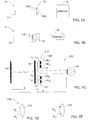
- the imaging system 10 utilizing an imaging lens arrangement 12 of the present invention.
- the imaging system 10 is formed by an object 13 that is to be imaged, the imaging lens arrangement 12, and a light detector unit 16.
- the imaging lens arrangement 12 includes a certain number of lenses 12A (generally at least one lens, single lens being shown in the present example) having a certain effective aperture D (which in the present example is the lens diameter), and a certain number of optical elements 12B (single element in the present example) associated with the lens(es) 12A.
- Such optical element 12B is configured and operable as an extended depth of focus (EDOF) element.
- EEOF extended depth of focus
- the optical element 12B is configured in accordance with the parameters of the lens 12A, i.e., its effective aperture and optionally also the optical power distribution and/or focal length.
- the optical element 12B is configured as a phase-affecting non-diffractive mask.
- the mask 12B is implemented integral with the lens, namely as a pattern on the lens surface.
- the mask 12B may be a separate element attached to the lens or located close thereto. This is illustrated in Fig. 1B showing an imaging system 100 utilizing a lens arrangement 112 that includes a lens 12A and a phase-affecting non-diffractive optical element 12B located close to the lens in front thereof.
- FIG. 1C shows schematically an imaging system 200 according to yet another example of the invention.
- an imaging lens arrangement 212 includes an array of lenses 12A, formed by four such lenses L 1 , L 2 , L 3 and L 4 in the present example, and an array 12B of optical elements OE 1 , OE 2 , OE 3 and OE 4 each associated with a corresponding lens of the lenslet array.
- Such system 200 may for example be used with a display panel or screen 13 (constituting an object) aimed at facilitating the imaging of the display/screen (e.g., of a mobile phone device) by people having close vision problems.
- the imaging arrangement 212 is accommodated at a small distance (a few millimeters from a surface 13' of the display panel 13.
- the optical elements' array 12B is located downstream of the lenslet array 12A with respect to light propagation from the object 13 towards a light detector 16 (patient's eye).
- lenslet' and EDOF elements' arrays provides for bringing the closest focus plane FP of the imaging arrangement 212 as close as possible to the object 13 plane, so that people with the close vision problems as well as people with normal vision will be able to see the screen.
- bringing the closest focus plane closer to the object plane reduces the demagnification ratio of the object that is to be focused.
- the optical element 12B is configured as a phase-only binary mask. It should, however be noted that generally the element 12B may be configured as a phase and amplitude mask.
- the optical element 12B is configured to define at least one spatially low frequency transition region, and, together with the lens 12A regions, define a predetermined pattern of spaced-apart substantially optically transparent features differently affecting the phase of light passing therethrough.
- the pattern is thus formed by one or more transition regions of the optical element, spaced by the regions of the lens, in the imaging lens plane.
- the transition regions are pi-phase transitions for a certain wavelength for which the mask 12B is designed.
- the arrangement of these transition regions (positions within the lens 12A plane) is determined by the effective aperture of the given imaging lens 12A (and possibly also optical power of the lens) so as to maximize the defocused OTF of the entire imaging arrangement.
- the pattern is such as to generate proper phase interference relation between light portions passing through different regions of the lens arrangement to thereby enable reducing a quadratic phase factor resulting from light getting out of focus of the imaging lens.
- the optical element may be implemented as a surface relief on the imaging lens (Fig. ID), namely, a pattern of spaced-apart regions R 1 and R 2 of variable lens thickness; or as a pattern of lens regions R'1 and R' 2 made of materials with different refractive indices n 1 and n 2 (Fig. IE).
- a certain optically transparent material of a refractive index different from that of the lens may be coated on selective spaced-apart regions of the lens surface.
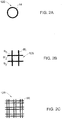
- Figs. 2A to 2C show two specific but not limiting examples, respectively, of the contour of the optical element 12B.
- the mask 12B is designed as an annular transition region 14 (generally, at least one such region; an array of concentric rings may be used as well).
- the mask is designed as a grid formed by two mutually perpendicular pairs of bars (lines) B 1 -B' 1 and B 2 -B' 2 .
- the element 12B is a mask formed by a two-dimensional array of basic grid-elements BE.
- the transition regions along the bar line are pi-phase transitions and the regions of intersection between the perpendicular bars are zero-phase transitions.
- the optimized contour for the optical element is obtained solving an algorithm, which will be described further below.
- the mask may and may not be symmetrical relative to the center of the lens.
- the four ⁇ -phase bars, two vertical (along Y-axis) and two horizontal (along X-axis) bars, that are illustrated in Fig. 2A may be shifted transversally along the x-y plane to be not centered around the center of the lens.
- each phase transition region may be of a variable spatially low frequency of phase transition such as for example ⁇ /2, ⁇ , ....
- the present invention provides the EDOF element 12B in the form of a mask of N segments within the effective aperture of the imaging lens 12A. It should be understood that instead of having a mask that blocks energy in some of segments and transmits in the other, the invention provides the substantially phase-only, non-diffractive mask 12B, that is either 1 or (-1) depending on the segment.
- the mask 12B is designed to maximize the defocused OTF of the imaging system, by generating invariance to quadratic phase factor (which factor is generated when the image is defocused and multiplies the CTF of the imaging lens).
- quadratic phase factor which factor is generated when the image is defocused and multiplies the CTF of the imaging lens.
- a search is made for the segments that will obtain the transmission value of (-1) such that the OTF, due to the out of focus distortion, is bounded as much as possible away from zero. Since the mask 12B is a binary phase mask, no energy efficiency consideration is used (the transmission is 100%). Following these criteria, a search is made over all the possibilities and combinations for the aperture coding mask.
- imaging lens refers here to the effective aperture thereof.
- OTF v CTF v ⁇ CTF v
- the auto correlation operation consists of shifting two CTF functions to the opposite directions, respectively, and then multiplying and summing the result.
- the so-obtained OTF relates to a spatial frequency that corresponds to the amount of the shift. At high frequencies (large shifts), the multiplication and the summing are averaged to zero in the case of out of focus. Hence, the OTF does not transmit high frequencies when the image is defocused.
- the phase mask (e.g., ring) of the present invention is aimed at reducing the high-frequency cancellation at large shifts of the CTF (the OTF is an auto correlation of the CTF).
- the mask is configured to invert the sign of part of the light field that before (i.e., pure lens with no EDOF correction) was averaged to zero (and this is why the OTF did not transmit the high spatial frequencies).
- the OTF is the Fourier transform of the intensity point spread function, and it is used to express the spatial-frequencies transmission function for intensity, when incoherent illumination is applied.
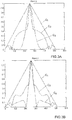
- Figs. 3A to 3D illustrate the effect of the present invention.
- curve C 1 corresponds to the MTF while at the in-focus state
- curve C 2 corresponds to the defocused MTF of an imaging system without the use of the correction optical element (EDOF element) of the present invention (mask 12B in Fig. 1 )
- curve C 3 corresponds to the defocused MTF of the system with the correction element.
- the transversal invariance may be obtained using the phase element producing periodic replication of the phase shape, namely lateral replication of the phase shape.
- Fig. 2C exemplifying a mask formed by a two-dimensional array of basic elements BE
- large lateral shifts high frequencies
- a complimentary part is inserted from another spatial period of the mask thus producing the phase period by replication.
- the replication of the basic period of the transitions thus reduces the sensitivity to lateral shifts.
- the longitudinal invariance is obtained as follows: Given the longitudinal distance between the phase element and a sensor (the imaging lens plane or the effective aperture plane), which is the lens of the human eye in case of ophthalmic applications, free space propagation of the mask function for this distance is considered. The result is a phase and amplitude distribution. The amplitude is dropped, leaving only the phase profile. In many cases, binarization of the phase function may provide sufficiently good results as well. The binarization realizes spatial mask which is easier for fabrication.
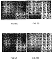
- FIGs. 4A-4I and Figs. 5A-5I illustrating how a face image looks like when the defocusing parameter 4 ⁇ /D 2 is varied from -0.2 ( Figs. 4A and 5A ) up to 0.2 ( Figs. 4I and 5I ) at steps of 0.05.
- Figs. 4A-4I show the case where the mask (optimally designed) of the present invention is used, and Figs. 5A-5I shows the case where no such aperture coding mask is used.
- the EDOF element configured similar to that of Fig. 2B was used.
- a difference in distortions between images of Figs. 4A-4I and 5A-5I exists due to the aperture coding mask of the present invention.
- Fig. 6 shows the results of examining the sensitivity of the coding mask (EDOF element) of the present invention to wavelength variations.
- an imaging lens arrangement imaging lens with a coding mask
- ⁇ 1 0.8 ⁇ 0
- ⁇ 0 the wavelength for which the mask was designed and fabricated to present pi-phase transition(s)
- the out of focus distortion obtained due to the usage of the mask is still very low despite the fact that the mask is no longer optimized (since the mask pattern features are pi-phase transitions for ⁇ 0 and not for ⁇ 1 ).
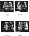
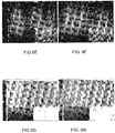
- Figs. 7A-7D show another experimental results obtained for imaging a Rosette.
- Fig. 7A shows an image corresponding to the in focus position of the Rosette obtained with no EDOF element of the invention
- Fig. 7B shows an in-focus image obtained with the EDOF element
- Fig. 7C corresponds to the out of focus position of the Rosette with no EDOF element
- Fig. 7D shows an image of the out of focus Rosette obtained with the EDOF improvement of the present invention.
- the EDOF element configured similar to that of Fig. 2A was used.
- the use of the EDOF element of the present invention provides improvement in spatial high frequencies and the effect on the input when the system is in focus.
- the inventor has performed experimental verification of the extended depth of focus approach for polychromatic spatially non coherent illumination (general lighting).
- the value of the phase factor ⁇ is computed following equation 2 above and using the distances and the diameter of the lens (affective aperture of the lens) in the optical system.
- the experimental results under these conditions are shown in Figs. 8A-8D and Figs. 9A-9H .
- the EDOF element configured similar to that of Fig. 2A was used.
- Fig. 8A corresponds to an in-focus position without the use of the optical element of the present invention
- Fig. 8B corresponds to the in-focus with such element
- Fig. 9A shows an in focus image obtained without the optical element
- Figs. 9D-9F correspond to Figs. 9A-9C but with the optical element
- the imaging lens arrangement of the present invention may be used for ophthalmic applications.
- the surface of the lens arrangement is to be flat.
- the fabrication techniques suitable to manufacture such an imaging lens arrangement include for example etching (wet or dry) or laser drilling or lathe grinding to obtain the desired spatial structure (surface relief), and then filling the evacuated volume by a material of a refraction index different from that of the lens, providing a refraction index difference is such that the outer region of the mask is flat while the desired phase difference is generated, required as buffering phase region that generates proper equalization between regions of the lens aperture for the interference effect.
- Another realization could be by diffusion or photo polymerization that does not include developing or removing of the polymerized material.
- Yet another approach which is related to eye surgery could be by implanting artificial tissue having difference in refraction index in comparison to the existing tissue of the eye.
- the EDOF element of the present invention (having no optical power) is added to the focal power of a certain lens which is to be obtained. For example, if a patient needs -1 diopter glasses and 3 diopters glasses for near and far visions, the EDOF element of the present invention may be appropriately designed to be used on either one of these glasses, being configured in accordance with the respective lens aperture to allow a depth of focus region equivalent to 5 diopters.
- a 1 diopter glasses with the EDOF element of the present invention can be used, where the EDOF element is operating around the optical power of the lens (1 diopter) and provides the depth of field region from -1.5 to 3.5 diopters.
- the patient may use only one pair of glasses with 1 diopter.
- This focal power of the glasses (imaging lens) will be added to the EDOF element.
- Such an EDOF element maximizes the defocused OTF of the lens arrangement (appropriately modulates the CTF profile of the imaging lens of the respective glasses) by generating proper phase interference relation between light portions passing through different regions of the lens, to reduce a quadratic phase factor resulting from light getting out of focus of the imaging lens.
- the inventor has found that for most patients a common EDOF element configuration can be used, preferably as that of Fig. 2C .
- the basic period (of the basic element BE ) is about 3mm
- a distance between two adjacent bars is about 1.875mm
- the bar thickness is about 0.375mm.
- the EDOF element with its range of depth of focus may be translated into Diopters range.
- the diameter of the eye lens (effective aperture of the imaging lens) varies from 2mm up to 6-7mm depending on the lighting conditions.
- the optical element generates a Diopter range within which the image is in focus.
- the inventor has found that for the resulted range of the phase factor ⁇ (about up to 17) for lightened environment in which the eye pupil has a diameter of 2mm, the obtained Diopter range P is more than 5 (from -2.5 up to 2.5).
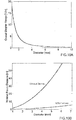
- Figs. 10A-10B present the simulation results visualizing the performance of the ophthalmic depth of focus application of the present invention.
- the simulation of Fig. 10A corresponds to the overall Diopter range obtained due to the fact that the EDOF element is attached to a contact lens.
- the diameter of the eye lens varies from 2mm up to 6-7mm depending on the lighting conditions.
- the simulations follow Eq. 6 above. '
- FIG. 1C exemplifying an imaging arrangement of the present invention formed by a lenslet array and an EDOF elements' array (suitable to be used with a display panel or screen), the required parameters of the imaging arrangement can be estimated as follows:
- u which is the distance between the screen 13 and the lenslet array 12A is about 2mm
- v which is the distance between the screen 13 and the closest focus plane FP is 40cm
- R which is the distance between the eye 16 and the closest focus plane FP
- the object 13 is constituted by the display of the mobile phone or the screen.
- this parameter can reach the value of 15 and without the EDOF element - the value of 2-3 without distorting the image quality.
- the diameter, D, of the lenses in the lenslet array can be found such that the minimal value for the distance between the screen 13 and the closest focus plane FP, (v min ), will be very close to the object plane 13 to have minimal demagnification.
- Attachment of the lenslet array 12A to the screen decreased the visible resolution.
- the resolution is not damaged by the imaging lenslet array.
- the technique of the present invention could be barrier breaking in a vast set of applications including, but not limited to, the following: conventional office devices containing camera such as camcorders, scanners (e.g., barcode scanners) and web cams; conventional imaging systems including camera and detectors, i.e. cellular cameras, car cameras, surveillances cameras, machine vision, photography, HDTV, video conferences, radar imaging systems (that typically suffer from defocus problems), endoscopy and passive bio medical inspections, tomography, display panels, etc.
- the usage of the depth of focus extending element of the present invention in endoscopy and passive biomedical inspections allows for in-body imaging to see organs in focus that otherwise are not, since there is no control on the exact position of the medical apparatus.
- Some other possible applications of the present invention include correcting chromatic aberrations in various optical systems, for example in optical communication; media reader/writers used with information carriers such as conventional DVD, or multi-layer information carriers utilizing light reflection or fluorescence.
- the present invention may also be used in ophthalmic applications as a contact lens, a spectacle lens, an intraocular lens, or any other lens used around or inserted into any part of the eye.
- An obvious example is the use of the invention for the benefit of short sighted (myopic) people who develop presbyopia, the need for reading glasses as a result of age-related changes in their natural eye lens.
- those people may use a single lens, as a spectacle lens, contact lens, intracorneal lens, phakic intraocular lens or aphakic intraocular lens, or a lens inserted elsewhere in the eye. In this fashion, they will use one lens for seeing at any distance, near or far.
- Another obvious utilization of the invention is in an intraocular lens, the artificial lens implanted in the eye after removal of a cataract.
- the regular artificial lens has only a single focus and thus the person into whose eye the lens was implanted has a very limited depth of focus and has to use spectacles for most distances of regard.
- Incorporation of the invention into the implanted lens will afford the patient focused vision at all distances.
- Another example of ophthalmic use is as a replacement of multifocal (progressive) spectacle lenses, which are conventionally designed such that every segment of the lens surface has a different focus and thus the patient has to move his eyes to focus on objects at different distances.
- Incorporation of the invention into a spectacle or contact lens will enable the presbyopic wearer to see objects in focus at all distances through any part of the lens.
- the image from objects at different distances are focused on the retina (or sensor) without appreciable loss of energy, in contradistinction to the situation in multifocal contact or intraocular lenses.
Landscapes
- Physics & Mathematics (AREA)
- Health & Medical Sciences (AREA)
- General Physics & Mathematics (AREA)
- Optics & Photonics (AREA)
- Ophthalmology & Optometry (AREA)
- General Health & Medical Sciences (AREA)
- Biomedical Technology (AREA)
- Life Sciences & Earth Sciences (AREA)
- Transplantation (AREA)
- Engineering & Computer Science (AREA)
- Cardiology (AREA)
- Heart & Thoracic Surgery (AREA)
- Vascular Medicine (AREA)
- Oral & Maxillofacial Surgery (AREA)
- Animal Behavior & Ethology (AREA)
- Public Health (AREA)
- Veterinary Medicine (AREA)
- Eyeglasses (AREA)
- Prostheses (AREA)
- Lenses (AREA)
Applications Claiming Priority (4)
| Application Number | Priority Date | Filing Date | Title |
|---|---|---|---|
| US60163804P | 2004-08-16 | 2004-08-16 | |
| US10/974,943 US7061693B2 (en) | 2004-08-16 | 2004-10-28 | Optical method and system for extended depth of focus |
| EP05770097.3A EP1779152B1 (de) | 2004-08-16 | 2005-08-11 | Verfahren und system zur erweiterung der schärfentiefe |
| PCT/IL2005/000868 WO2006018834A1 (en) | 2004-08-16 | 2005-08-11 | Method and system for extended depth of focus |
Related Parent Applications (1)
| Application Number | Title | Priority Date | Filing Date |
|---|---|---|---|
| EP05770097.3A Division EP1779152B1 (de) | 2004-08-16 | 2005-08-11 | Verfahren und system zur erweiterung der schärfentiefe |
Publications (2)
| Publication Number | Publication Date |
|---|---|
| EP3364220A1 true EP3364220A1 (de) | 2018-08-22 |
| EP3364220B1 EP3364220B1 (de) | 2024-05-01 |
Family
ID=35159655
Family Applications (3)
| Application Number | Title | Priority Date | Filing Date |
|---|---|---|---|
| EP05770097.3A Active EP1779152B1 (de) | 2004-08-16 | 2005-08-11 | Verfahren und system zur erweiterung der schärfentiefe |
| EP17202513.2A Active EP3364220B1 (de) | 2004-08-16 | 2005-08-11 | Verfahren und system zur erweiterung der tiefenschärfe |
| EP10183895A Withdrawn EP2302421A1 (de) | 2004-08-16 | 2005-08-11 | System mit erweiterter Schärfentiefe |
Family Applications Before (1)
| Application Number | Title | Priority Date | Filing Date |
|---|---|---|---|
| EP05770097.3A Active EP1779152B1 (de) | 2004-08-16 | 2005-08-11 | Verfahren und system zur erweiterung der schärfentiefe |
Family Applications After (1)
| Application Number | Title | Priority Date | Filing Date |
|---|---|---|---|
| EP10183895A Withdrawn EP2302421A1 (de) | 2004-08-16 | 2005-08-11 | System mit erweiterter Schärfentiefe |
Country Status (9)
| Country | Link |
|---|---|
| US (1) | US7061693B2 (de) |
| EP (3) | EP1779152B1 (de) |
| JP (1) | JP5036540B2 (de) |
| KR (1) | KR101165051B1 (de) |
| CN (1) | CN101014884B (de) |
| ES (1) | ES2660408T3 (de) |
| HU (1) | HUE036169T2 (de) |
| RU (1) | RU2436135C2 (de) |
| WO (1) | WO2006018834A1 (de) |
Families Citing this family (189)
| Publication number | Priority date | Publication date | Assignee | Title |
|---|---|---|---|---|
| US7773316B2 (en) * | 2003-01-16 | 2010-08-10 | Tessera International, Inc. | Optics for an extended depth of field |
| WO2004063989A2 (en) * | 2003-01-16 | 2004-07-29 | D-Blur Technologies Ltd. | Camera with image enhancement functions |
| US8294999B2 (en) | 2003-01-16 | 2012-10-23 | DigitalOptics Corporation International | Optics for an extended depth of field |
| US7628810B2 (en) | 2003-05-28 | 2009-12-08 | Acufocus, Inc. | Mask configured to maintain nutrient transport without producing visible diffraction patterns |
| CN1898590A (zh) | 2003-12-01 | 2007-01-17 | Cdm光学有限公司 | 用于优化光学和数字系统设计的系统和方法 |
| US7944467B2 (en) * | 2003-12-01 | 2011-05-17 | Omnivision Technologies, Inc. | Task-based imaging systems |
| US7365917B2 (en) * | 2004-08-16 | 2008-04-29 | Xceed Imaging Ltd. | Optical method and system for extended depth of focus |
| JP5033802B2 (ja) * | 2005-09-19 | 2012-09-26 | オムニビジョン テクノロジーズ, インコーポレイテッド | タスク型画像化システム |
| US20070239417A1 (en) * | 2006-03-31 | 2007-10-11 | D-Blur Technologies Ltd. | Camera performance simulation |
| EP2016456A4 (de) * | 2006-04-20 | 2010-08-25 | Xceed Imaging Ltd | Durchweg optisches system und verfahren zur bereitstellung einer vergrösserten schärfentiefe bei der abbildung |
| EP2008143B1 (de) * | 2006-04-20 | 2012-04-11 | Xceed Imaging Ltd. | System und verfahren für die bildgebung mit erweiterter fokustiefe und nicht kohärentem licht |
| WO2007141788A2 (en) * | 2006-06-06 | 2007-12-13 | Xceed Imaging Ltd. | Optical system and method for multi-range and dual-range imaging |
| EP2069851A4 (de) * | 2006-09-14 | 2010-02-24 | Tessera Tech Hungary Kft | Abbildungssystem mit flexiblen anordnungstoleranzen und entsprechende verfahren |
| EP2104877A4 (de) * | 2006-09-14 | 2010-02-24 | Tessera Tech Hungary Kft | Abbildungssystem mit erhöhter bildqualität und entsprechende verfahren |
| US7646549B2 (en) * | 2006-12-18 | 2010-01-12 | Xceed Imaging Ltd | Imaging system and method for providing extended depth of focus, range extraction and super resolved imaging |
| EP1952752B2 (de) * | 2007-01-31 | 2019-10-16 | Richard Wolf GmbH | Endoskopsystem |
| EP1978394A1 (de) * | 2007-04-06 | 2008-10-08 | Global Bionic Optics Pty Ltd. | Optisches System zum Vergrößern der Tiefenschärfe |
| BRPI0814757A2 (pt) * | 2007-08-02 | 2015-03-03 | Ocular Optics Inc | Sistema e métodos de lentes intraocular multi-focal |
| US8747466B2 (en) * | 2007-08-27 | 2014-06-10 | Amo Groningen, B.V. | Intraocular lens having extended depth of focus |
| US9216080B2 (en) * | 2007-08-27 | 2015-12-22 | Amo Groningen B.V. | Toric lens with decreased sensitivity to cylinder power and rotation and method of using the same |
| US8974526B2 (en) | 2007-08-27 | 2015-03-10 | Amo Groningen B.V. | Multizonal lens with extended depth of focus |
| US8740978B2 (en) * | 2007-08-27 | 2014-06-03 | Amo Regional Holdings | Intraocular lens having extended depth of focus |
| US20090062911A1 (en) * | 2007-08-27 | 2009-03-05 | Amo Groningen Bv | Multizonal lens with extended depth of focus |
| CA2715537C (en) | 2008-02-15 | 2016-09-06 | Amo Regional Holdings | System, ophthalmic lens, and method for extending depth of focus |
| US8439498B2 (en) | 2008-02-21 | 2013-05-14 | Abbott Medical Optics Inc. | Toric intraocular lens with modified power characteristics |
| EP2891918A1 (de) * | 2008-02-29 | 2015-07-08 | Global Bionic Optics Pty Ltd. | Einlinsen-Abbildungssysteme mit erweiterter Tiefenschärfe |
| DE102008018636B4 (de) * | 2008-04-11 | 2011-01-05 | Storz Endoskop Produktions Gmbh | Vorrichtung und Verfahren zur endoskopischen 3D-Datenerfassung |
| US8231219B2 (en) | 2008-04-24 | 2012-07-31 | Amo Groningen B.V. | Diffractive lens exhibiting enhanced optical performance |
| US7871162B2 (en) * | 2008-04-24 | 2011-01-18 | Amo Groningen B.V. | Diffractive multifocal lens having radially varying light distribution |
| KR101422503B1 (ko) * | 2008-05-09 | 2014-07-25 | 삼성전자주식회사 | 연장된 초점 심도를 갖는 렌즈 및 이를 포함하는 광학시스템 |
| US9335563B2 (en) | 2012-08-31 | 2016-05-10 | Amo Groningen B.V. | Multi-ring lens, systems and methods for extended depth of focus |
| US8862447B2 (en) | 2010-04-30 | 2014-10-14 | Amo Groningen B.V. | Apparatus, system and method for predictive modeling to design, evaluate and optimize ophthalmic lenses |
| US8866920B2 (en) | 2008-05-20 | 2014-10-21 | Pelican Imaging Corporation | Capturing and processing of images using monolithic camera array with heterogeneous imagers |
| US11792538B2 (en) | 2008-05-20 | 2023-10-17 | Adeia Imaging Llc | Capturing and processing of images including occlusions focused on an image sensor by a lens stack array |
| JP2011523538A (ja) | 2008-05-20 | 2011-08-11 | ペリカン イメージング コーポレイション | 異なる種類の撮像装置を有するモノリシックカメラアレイを用いた画像の撮像および処理 |
| KR20110104963A (ko) * | 2008-12-19 | 2011-09-23 | 노파르티스 아게 | 눈의 주변 디포커스의 교정 및 굴절 이상 발생의 조절 |
| US8292952B2 (en) | 2009-03-04 | 2012-10-23 | Aaren Scientific Inc. | System for forming and modifying lenses and lenses formed thereby |
| US8646916B2 (en) | 2009-03-04 | 2014-02-11 | Perfect Ip, Llc | System for characterizing a cornea and obtaining an opthalmic lens |
| WO2010102156A1 (en) * | 2009-03-04 | 2010-09-10 | Aaren Scientific Inc. | System for characterizing a cornea and obtaining an ophthalmic lens |
| EP2228677A1 (de) * | 2009-03-09 | 2010-09-15 | Global Bionic Optics Pty Ltd. | Überwachungsbildgebungssystem mit erweiterter Schärfentiefe |
| ES2970433T3 (es) | 2009-08-13 | 2024-05-28 | Acufocus Inc | Método de fabricación de implantes intraoculares con máscara y lentes |
| US10004593B2 (en) * | 2009-08-13 | 2018-06-26 | Acufocus, Inc. | Intraocular lens with elastic mask |
| CN101995646B (zh) * | 2009-08-17 | 2013-03-27 | 大立光电股份有限公司 | 取像透镜系统 |
| WO2011035033A1 (en) | 2009-09-16 | 2011-03-24 | Indiana University Research & Technology Corporation | Simultaneous vision lenses, design strategies, apparatuses, methods, and systems |
| US20120281280A1 (en) | 2009-10-15 | 2012-11-08 | Sony Corporation | Birefringent device with application specific pupil function and optical device |
| EP2502115A4 (de) | 2009-11-20 | 2013-11-06 | Pelican Imaging Corp | Aufnahme und verarbeitung von bildern mittels eines monolithischen kameraarrays mit heterogenem bildwandler |
| US8325420B2 (en) * | 2009-11-24 | 2012-12-04 | Massachusetts Institute Of Technology | Annular solid immersion lenses and methods of making them |
| US8339481B2 (en) * | 2009-12-14 | 2012-12-25 | Samsung Electronics Co., Ltd. | Image restoration devices adapted to remove artifacts from a restored image and associated image restoration methods |
| CN102892381A (zh) * | 2009-12-18 | 2013-01-23 | Amo格罗宁根私人有限公司 | 有限光栅镜片、系统和方法 |
| US8531783B2 (en) | 2010-02-09 | 2013-09-10 | Xceed Imaging Ltd. | Imaging method and system for imaging with extended depth of focus |
| US8416334B2 (en) | 2010-04-27 | 2013-04-09 | Fm-Assets Pty Ltd. | Thick single-lens extended depth-of-field imaging systems |
| KR101756910B1 (ko) | 2010-05-11 | 2017-07-26 | 삼성전자주식회사 | 감쇠 패턴을 포함하는 마스크를 이용한 광 필드 영상 처리 장치 및 방법 |
| US20120012748A1 (en) | 2010-05-12 | 2012-01-19 | Pelican Imaging Corporation | Architectures for imager arrays and array cameras |
| WO2012037154A2 (en) | 2010-09-13 | 2012-03-22 | The Regents Of The University Of Colorado, A Body Corporate | Extended depth of field optics with variable pupil diameter |
| RU2622988C2 (ru) * | 2010-12-01 | 2017-06-21 | Эдленс Бикен, Инк. | Эндоскоп с изменяемой оптической силой на основе технологии жидкой линзы |
| WO2012073112A1 (en) | 2010-12-01 | 2012-06-07 | Amo Groningen B.V. | A multifocal lens having an optical add power progression, and a system and method of providing same |
| US8878950B2 (en) | 2010-12-14 | 2014-11-04 | Pelican Imaging Corporation | Systems and methods for synthesizing high resolution images using super-resolution processes |
| US8894204B2 (en) | 2010-12-17 | 2014-11-25 | Abbott Medical Optics Inc. | Ophthalmic lens, systems and methods having at least one rotationally asymmetric diffractive structure |
| US9931200B2 (en) | 2010-12-17 | 2018-04-03 | Amo Groningen B.V. | Ophthalmic devices, systems, and methods for optimizing peripheral vision |
| WO2012085917A1 (en) * | 2010-12-23 | 2012-06-28 | Xceed Imaging Ltd. | Toric ophthalmic lens having extended depth of focus |
| WO2012120470A1 (en) * | 2011-03-10 | 2012-09-13 | Optika Amuka (A.A.) Ltd. | Stereographic viewing with extended depth of field |
| WO2012138426A2 (en) * | 2011-04-04 | 2012-10-11 | Elenza, Inc. | An implantable ophthalmic device with multiple static apertures |
| WO2012141953A1 (en) * | 2011-04-07 | 2012-10-18 | Novartis Ag | Optical structures with nanostructre features and methods of use and manufacture |
| EP2708019B1 (de) | 2011-05-11 | 2019-10-16 | FotoNation Limited | Systeme und verfahren zum senden und empfangen von arraykamera-bilddaten |
| US20130265459A1 (en) | 2011-06-28 | 2013-10-10 | Pelican Imaging Corporation | Optical arrangements for use with an array camera |
| US20130070060A1 (en) | 2011-09-19 | 2013-03-21 | Pelican Imaging Corporation | Systems and methods for determining depth from multiple views of a scene that include aliasing using hypothesized fusion |
| US8542933B2 (en) | 2011-09-28 | 2013-09-24 | Pelican Imaging Corporation | Systems and methods for decoding light field image files |
| US8937646B1 (en) * | 2011-10-05 | 2015-01-20 | Amazon Technologies, Inc. | Stereo imaging using disparate imaging devices |
| US9545303B2 (en) | 2011-12-02 | 2017-01-17 | Acufocus, Inc. | Ocular mask having selective spectral transmission |
| TWI554244B (zh) * | 2011-12-19 | 2016-10-21 | 愛爾康眼科手術激光股份有限公司 | 用於雷射白內障程序之手術內光學同調斷層掃描成像的影像處理器 |
| US9066784B2 (en) * | 2011-12-19 | 2015-06-30 | Alcon Lensx, Inc. | Intra-surgical optical coherence tomographic imaging of cataract procedures |
| US10656437B2 (en) | 2011-12-21 | 2020-05-19 | Brien Holden Vision Institute Limited | Optical lens with halo reduction |
| US8556417B2 (en) * | 2012-02-02 | 2013-10-15 | Novartis Ag | Apodized hybrid diffractive-refractive IOL for pseudo-accommodation |
| GB201201936D0 (en) | 2012-02-03 | 2012-03-21 | Univ Southampton | Super-oscillatory lens device |
| WO2013126578A1 (en) | 2012-02-21 | 2013-08-29 | Pelican Imaging Corporation | Systems and methods for the manipulation of captured light field image data |
| CN104204893B (zh) * | 2012-03-30 | 2016-08-24 | 三菱丽阳株式会社 | 棒状透镜阵列和使用棒状透镜阵列的图像传感器头 |
| TWI588560B (zh) | 2012-04-05 | 2017-06-21 | 布萊恩荷登視覺協會 | 用於屈光不正之鏡片、裝置、方法及系統 |
| US9210392B2 (en) | 2012-05-01 | 2015-12-08 | Pelican Imaging Coporation | Camera modules patterned with pi filter groups |
| CN104508681B (zh) | 2012-06-28 | 2018-10-30 | Fotonation开曼有限公司 | 用于检测有缺陷的相机阵列、光学器件阵列和传感器的系统及方法 |
| US20140002674A1 (en) | 2012-06-30 | 2014-01-02 | Pelican Imaging Corporation | Systems and Methods for Manufacturing Camera Modules Using Active Alignment of Lens Stack Arrays and Sensors |
| US8619082B1 (en) | 2012-08-21 | 2013-12-31 | Pelican Imaging Corporation | Systems and methods for parallax detection and correction in images captured using array cameras that contain occlusions using subsets of images to perform depth estimation |
| US20140055632A1 (en) | 2012-08-23 | 2014-02-27 | Pelican Imaging Corporation | Feature based high resolution motion estimation from low resolution images captured using an array source |
| WO2014043641A1 (en) | 2012-09-14 | 2014-03-20 | Pelican Imaging Corporation | Systems and methods for correcting user identified artifacts in light field images |
| US20140092281A1 (en) | 2012-09-28 | 2014-04-03 | Pelican Imaging Corporation | Generating Images from Light Fields Utilizing Virtual Viewpoints |
| US11126040B2 (en) | 2012-09-30 | 2021-09-21 | Optica Amuka (A.A.) Ltd. | Electrically-tunable lenses and lens systems |
| ES2727498T3 (es) | 2012-09-30 | 2019-10-16 | Optica Amuka A A Ltd | Lentes con potencia y alineación eléctricamente ajustable |
| US9201250B2 (en) | 2012-10-17 | 2015-12-01 | Brien Holden Vision Institute | Lenses, devices, methods and systems for refractive error |
| US9541773B2 (en) | 2012-10-17 | 2017-01-10 | Brien Holden Vision Institute | Lenses, devices, methods and systems for refractive error |
| WO2014078443A1 (en) | 2012-11-13 | 2014-05-22 | Pelican Imaging Corporation | Systems and methods for array camera focal plane control |
| AU2013353764B2 (en) | 2012-12-04 | 2018-12-06 | Amo Groningen B.V. | Lenses systems and methods for providing binocular customized treatments to correct presbyopia |
| FR2999300B1 (fr) * | 2012-12-07 | 2022-06-03 | Thales Sa | Systeme optique comportant un filtre optique a masque de phase et/ou d'amplitude a motif periodique |
| US9462164B2 (en) | 2013-02-21 | 2016-10-04 | Pelican Imaging Corporation | Systems and methods for generating compressed light field representation data using captured light fields, array geometry, and parallax information |
| WO2014133974A1 (en) | 2013-02-24 | 2014-09-04 | Pelican Imaging Corporation | Thin form computational and modular array cameras |
| AU2014224341B2 (en) | 2013-03-07 | 2018-06-07 | Amo Groningen B.V. | Lens providing extended depth of focus and method relating to same |
| US9774789B2 (en) | 2013-03-08 | 2017-09-26 | Fotonation Cayman Limited | Systems and methods for high dynamic range imaging using array cameras |
| US8866912B2 (en) | 2013-03-10 | 2014-10-21 | Pelican Imaging Corporation | System and methods for calibration of an array camera using a single captured image |
| US9521416B1 (en) | 2013-03-11 | 2016-12-13 | Kip Peli P1 Lp | Systems and methods for image data compression |
| EP2967312B1 (de) | 2013-03-11 | 2019-04-24 | Johnson & Johnson Surgical Vision, Inc. | Intraokularlinse mit anpassung einer bildoberfläche an eine retinale form und entwurfsverfahren dafür |
| US9519972B2 (en) | 2013-03-13 | 2016-12-13 | Kip Peli P1 Lp | Systems and methods for synthesizing images from image data captured by an array camera using restricted depth of field depth maps in which depth estimation precision varies |
| US9106784B2 (en) | 2013-03-13 | 2015-08-11 | Pelican Imaging Corporation | Systems and methods for controlling aliasing in images captured by an array camera for use in super-resolution processing |
| US9888194B2 (en) | 2013-03-13 | 2018-02-06 | Fotonation Cayman Limited | Array camera architecture implementing quantum film image sensors |
| WO2014164550A2 (en) | 2013-03-13 | 2014-10-09 | Pelican Imaging Corporation | System and methods for calibration of an array camera |
| US9427922B2 (en) | 2013-03-14 | 2016-08-30 | Acufocus, Inc. | Process for manufacturing an intraocular lens with an embedded mask |
| US9100586B2 (en) | 2013-03-14 | 2015-08-04 | Pelican Imaging Corporation | Systems and methods for photometric normalization in array cameras |
| US9578259B2 (en) | 2013-03-14 | 2017-02-21 | Fotonation Cayman Limited | Systems and methods for reducing motion blur in images or video in ultra low light with array cameras |
| US9497429B2 (en) | 2013-03-15 | 2016-11-15 | Pelican Imaging Corporation | Extended color processing on pelican array cameras |
| JP2016524125A (ja) | 2013-03-15 | 2016-08-12 | ペリカン イメージング コーポレイション | カメラアレイを用いた立体撮像のためのシステムおよび方法 |
| US9445003B1 (en) | 2013-03-15 | 2016-09-13 | Pelican Imaging Corporation | Systems and methods for synthesizing high resolution images using image deconvolution based on motion and depth information |
| US9497370B2 (en) | 2013-03-15 | 2016-11-15 | Pelican Imaging Corporation | Array camera architecture implementing quantum dot color filters |
| US9633442B2 (en) | 2013-03-15 | 2017-04-25 | Fotonation Cayman Limited | Array cameras including an array camera module augmented with a separate camera |
| US10122993B2 (en) | 2013-03-15 | 2018-11-06 | Fotonation Limited | Autofocus system for a conventional camera that uses depth information from an array camera |
| AU2013394132B2 (en) * | 2013-07-08 | 2016-10-13 | Alcon Inc. | Technique for treating presbyopia |
| US9898856B2 (en) | 2013-09-27 | 2018-02-20 | Fotonation Cayman Limited | Systems and methods for depth-assisted perspective distortion correction |
| US9426343B2 (en) | 2013-11-07 | 2016-08-23 | Pelican Imaging Corporation | Array cameras incorporating independently aligned lens stacks |
| WO2015074078A1 (en) | 2013-11-18 | 2015-05-21 | Pelican Imaging Corporation | Estimating depth from projected texture using camera arrays |
| US9456134B2 (en) | 2013-11-26 | 2016-09-27 | Pelican Imaging Corporation | Array camera configurations incorporating constituent array cameras and constituent cameras |
| RU2675688C2 (ru) * | 2013-12-23 | 2018-12-21 | Новартис Аг | Хирургическая система визуализации oct широкого поля обзора без использования микроскопа |
| US10089740B2 (en) | 2014-03-07 | 2018-10-02 | Fotonation Limited | System and methods for depth regularization and semiautomatic interactive matting using RGB-D images |
| AU2015242298B2 (en) | 2014-03-10 | 2019-11-14 | Amo Groningen B.V. | Intraocular lens that improves overall vision where there is a local loss of retinal function |
| AU2015262976B2 (en) | 2014-04-21 | 2020-02-27 | Amo Groningen B.V. | Ophthalmic devices, system and methods that improve peripheral vision |
| AU2015270158B2 (en) | 2014-06-05 | 2017-11-09 | Optica Amuka (A.A.) Ltd. | Control of dynamic lenses |
| US9521319B2 (en) | 2014-06-18 | 2016-12-13 | Pelican Imaging Corporation | Array cameras and array camera modules including spectral filters disposed outside of a constituent image sensor |
| RU2595759C2 (ru) * | 2014-07-04 | 2016-08-27 | Самсунг Электроникс Ко., Лтд. | Способ и устройство для захвата изображения и одновременного извлечения глубины |
| WO2016003253A1 (en) | 2014-07-04 | 2016-01-07 | Samsung Electronics Co., Ltd. | Method and apparatus for image capturing and simultaneous depth extraction |
| CN111265331B (zh) | 2014-09-09 | 2022-09-09 | 斯塔尔外科有限公司 | 具有扩展的景深和增强的远距视力的眼科植入物 |
| ES2529267B1 (es) | 2014-09-25 | 2015-12-18 | Sergio Oscar Luque | Lente intraocular multifocal con profundidad de campo extendida |
| WO2016054089A1 (en) | 2014-09-29 | 2016-04-07 | Pelican Imaging Corporation | Systems and methods for dynamic calibration of array cameras |
| US9943403B2 (en) | 2014-11-19 | 2018-04-17 | Acufocus, Inc. | Fracturable mask for treating presbyopia |
| US9942474B2 (en) | 2015-04-17 | 2018-04-10 | Fotonation Cayman Limited | Systems and methods for performing high speed video capture and depth estimation using array cameras |
| ES2972581T3 (es) | 2015-10-05 | 2024-06-13 | Acufocus Inc | Métodos de moldeo de lentes intraoculares |
| EP3373857B1 (de) * | 2015-11-09 | 2022-08-31 | HOYA Corporation | Optische vorrichtungen mit teilweiser oder unvollständiger optik |
| US11464625B2 (en) | 2015-11-24 | 2022-10-11 | Acufocus, Inc. | Toric small aperture intraocular lens with extended depth of focus |
| WO2017137839A1 (en) | 2016-02-09 | 2017-08-17 | Amo Groningen B.V. | Progressive power intraocular lens, and methods of use and manufacture |
| US11083566B2 (en) | 2016-02-29 | 2021-08-10 | Alcon Inc. | Ophthalmic lens having an extended depth of focus |
| US9968440B2 (en) * | 2016-02-29 | 2018-05-15 | Novartis Ag | Ophthalmic lens having an extended depth of focus |
| SG11201807531TA (en) | 2016-03-09 | 2018-09-27 | Staar Surgical Co | Ophthalmic implants with extended depth of field and enhanced distance visual acuity |
| US10588738B2 (en) | 2016-03-11 | 2020-03-17 | Amo Groningen B.V. | Intraocular lenses that improve peripheral vision |
| CA3018545A1 (en) | 2016-03-23 | 2017-09-28 | Johnson & Johnson Surgical Vision, Inc. | Power calculator for an ophthalmic apparatus with corrective meridians having extended tolerance or operation band |
| US10670885B2 (en) | 2016-03-23 | 2020-06-02 | Johnson & Johnson Surgical Vision, Inc. | Ophthalmic apparatus with corrective meridians having extended tolerance band with freeform refractive surfaces |
| ES2904889T3 (es) | 2016-04-17 | 2022-04-06 | Optica Amuka A A Ltd | Lente para gafas que comprende una lente de cristal líquido con accionamiento eléctrico mejorado |
| WO2017182878A1 (en) | 2016-04-19 | 2017-10-26 | Amo Groningen B.V. | Ophthalmic devices, system and methods that improve peripheral vision |
| WO2017216716A1 (en) | 2016-06-16 | 2017-12-21 | Optica Amuka (A.A.) Ltd. | Tunable lenses for spectacles |
| CA3041404A1 (en) | 2016-10-25 | 2018-05-03 | Amo Groningen B.V. | Realistic eye models to design and evaluate intraocular lenses for a large field of view |
| WO2018115372A1 (en) * | 2016-12-23 | 2018-06-28 | Iee International Electronics & Engineering S.A. | High-resolution 3d radar wave imaging device |
| CA3056707A1 (en) | 2017-03-17 | 2018-09-20 | Amo Groningen B.V. | Diffractive intraocular lenses for extended range of vision |
| US10739227B2 (en) | 2017-03-23 | 2020-08-11 | Johnson & Johnson Surgical Vision, Inc. | Methods and systems for measuring image quality |
| DE112018002670T5 (de) | 2017-05-24 | 2020-03-05 | The Trustees Of Columbia University In The City Of New York | Breitband achromatische flache optische Komponenten durch dispersionstechnische dielektrische Metaoberflächen |
| US11523897B2 (en) | 2017-06-23 | 2022-12-13 | Amo Groningen B.V. | Intraocular lenses for presbyopia treatment |
| WO2019002390A1 (en) | 2017-06-28 | 2019-01-03 | Amo Groningen B.V. | EXTENDED BEACH AND ASSOCIATED INTRAOCULAR LENSES FOR THE TREATMENT OF PRESBYOPIA |
| AU2018292024A1 (en) | 2017-06-28 | 2020-01-02 | Amo Groningen B.V. | Diffractive lenses and related intraocular lenses for presbyopia treatment |
| US11327210B2 (en) | 2017-06-30 | 2022-05-10 | Amo Groningen B.V. | Non-repeating echelettes and related intraocular lenses for presbyopia treatment |
| WO2019012385A1 (en) | 2017-07-10 | 2019-01-17 | Optica Amuka (A.A.) Ltd. | SYSTEMS OF VIRTUAL REALITY AND INCREASED REALITY WITH DYNAMIC VISION CORRECTION |
| US11953764B2 (en) | 2017-07-10 | 2024-04-09 | Optica Amuka (A.A.) Ltd. | Tunable lenses with enhanced performance features |
| US10482618B2 (en) | 2017-08-21 | 2019-11-19 | Fotonation Limited | Systems and methods for hybrid depth regularization |
| WO2019046827A1 (en) | 2017-08-31 | 2019-03-07 | Metalenz, Inc. | INTEGRATION OF TRANSMISSIVE METASURFACE LENS |
| US11556012B2 (en) | 2017-10-16 | 2023-01-17 | Optica Amuka (A.A.) Ltd. | Spectacles with electrically-tunable lenses controllable by an external system |
| CN107589543B (zh) * | 2017-10-18 | 2020-01-31 | 重庆大学 | 一种基于归一化频谱压缩的长焦深聚焦透镜及设计方法 |
| CA3082053A1 (en) | 2017-11-30 | 2019-06-06 | Amo Groningen B.V. | Intraocular lenses that improve post-surgical spectacle independent and methods of manufacturing thereof |
| US10832023B2 (en) | 2017-12-15 | 2020-11-10 | Cognex Corporation | Dual-imaging vision system camera and method for using the same |
| US11301655B2 (en) | 2017-12-15 | 2022-04-12 | Cognex Corporation | Vision imaging system having a camera and dual aimer assemblies |
| CN108325047B (zh) * | 2018-03-26 | 2020-09-08 | 青岛市中心医院 | 一种体外导向心导管装置 |
| WO2019217471A1 (en) | 2018-05-09 | 2019-11-14 | Acufocus, Inc. | Intraocular implant with removable optic |
| EP3739375A4 (de) | 2018-07-03 | 2021-10-20 | National University Corporation Tokyo University of Agriculture and Technology | Stereoskopische brille, verfahren zum entwurf eines darin verwendeten brillenglases und verfahren zur beobachtung eines stereoskopischen bildes |
| KR20230113645A (ko) | 2018-08-17 | 2023-07-31 | 스타 서지컬 컴퍼니 | 나노 구배의 굴절률을 나타내는 중합체 조성물 |
| CN109683429A (zh) * | 2019-02-27 | 2019-04-26 | 中国科学院上海技术物理研究所 | 一种提升复杂环境下小f数大视场相机工作稳定性的方法 |
| CN113557463B (zh) * | 2019-03-08 | 2024-08-20 | Pcms控股公司 | 用于基于具有扩展焦深的光束的显示器的光学方法和系统 |
| US11978752B2 (en) | 2019-07-26 | 2024-05-07 | Metalenz, Inc. | Aperture-metasurface and hybrid refractive-metasurface imaging systems |
| US11172112B2 (en) | 2019-09-09 | 2021-11-09 | Embedtek, LLC | Imaging system including a non-linear reflector |
| MX2022003020A (es) | 2019-09-17 | 2022-06-14 | Boston Polarimetrics Inc | Sistemas y metodos para modelado de superficie usando se?ales de polarizacion. |
| JP7330376B2 (ja) | 2019-10-07 | 2023-08-21 | ボストン ポーラリメトリックス,インコーポレイティド | 偏光によるセンサシステム及び撮像システムの増強のための方法 |
| CN110763161B (zh) * | 2019-11-22 | 2024-04-09 | 安徽大学 | 一种基于强度传输方程的三维重构数据采集系统 |
| WO2021108002A1 (en) | 2019-11-30 | 2021-06-03 | Boston Polarimetrics, Inc. | Systems and methods for transparent object segmentation using polarization cues |
| EP4085292A1 (de) | 2019-12-30 | 2022-11-09 | AMO Groningen B.V. | Linsen, die beugungsprofile mit unregelmässiger breite für die sehbehandlung aufweisen |
| US11886046B2 (en) | 2019-12-30 | 2024-01-30 | Amo Groningen B.V. | Multi-region refractive lenses for vision treatment |
| KR20220132620A (ko) | 2020-01-29 | 2022-09-30 | 인트린식 이노베이션 엘엘씨 | 물체 포즈 검출 및 측정 시스템들을 특성화하기 위한 시스템들 및 방법들 |
| CN115428028A (zh) | 2020-01-30 | 2022-12-02 | 因思创新有限责任公司 | 用于合成用于在包括偏振图像的不同成像模态下训练统计模型的数据的系统和方法 |
| CA3167325A1 (en) * | 2020-02-12 | 2021-08-19 | Ravi Chandra Bakaraju | Spectacle lenses with auxiliary optical elements |
| KR20220144866A (ko) * | 2020-03-01 | 2022-10-27 | 엔탈믹 홀딩 피티와이 리미티드 | 근시 관리를 위한 콘택트 렌즈 장치 |
| CN111521617B (zh) * | 2020-04-30 | 2023-06-16 | 上海御微半导体技术有限公司 | 光学检测设备、光学检测设备的控制方法及存储介质 |
| US11953700B2 (en) | 2020-05-27 | 2024-04-09 | Intrinsic Innovation Llc | Multi-aperture polarization optical systems using beam splitters |
| US12069227B2 (en) | 2021-03-10 | 2024-08-20 | Intrinsic Innovation Llc | Multi-modal and multi-spectral stereo camera arrays |
| US12020455B2 (en) | 2021-03-10 | 2024-06-25 | Intrinsic Innovation Llc | Systems and methods for high dynamic range image reconstruction |
| US11290658B1 (en) | 2021-04-15 | 2022-03-29 | Boston Polarimetrics, Inc. | Systems and methods for camera exposure control |
| US11954886B2 (en) | 2021-04-15 | 2024-04-09 | Intrinsic Innovation Llc | Systems and methods for six-degree of freedom pose estimation of deformable objects |
| US12067746B2 (en) | 2021-05-07 | 2024-08-20 | Intrinsic Innovation Llc | Systems and methods for using computer vision to pick up small objects |
| US20240264467A1 (en) * | 2021-06-03 | 2024-08-08 | Brien Holden Vision Institute Limited | Ophthalmic Lenses Utilizing Binary Amplitude Modulation |
| US11689813B2 (en) | 2021-07-01 | 2023-06-27 | Intrinsic Innovation Llc | Systems and methods for high dynamic range imaging using crossed polarizers |
| ES2895799B2 (es) * | 2021-07-06 | 2023-12-13 | Univ Madrid Complutense | Lente oftálmica refracto-difractiva con profundidad de foco extendida |
| US11927769B2 (en) | 2022-03-31 | 2024-03-12 | Metalenz, Inc. | Polarization sorting metasurface microlens array device |
Citations (29)
| Publication number | Priority date | Publication date | Assignee | Title |
|---|---|---|---|---|
| EP0369561A2 (de) | 1988-11-16 | 1990-05-23 | BAUSCH & LOMB INCORPORATED | System und Verfahren zur Herstellung von diffraktiven Kontakt- und Intraokularlinsen |
| US4955904A (en) | 1989-08-21 | 1990-09-11 | The Beth Israel Hospital Association | Masked intraocular lens and method for treating a patient with cataracts |
| US5114220A (en) * | 1988-05-19 | 1992-05-19 | Essilor International, Compagnie Generale D'optique | Multiple contour diffractive lens |
| US5225858A (en) | 1987-06-01 | 1993-07-06 | Valdemar Portney | Multifocal ophthalmic lens |
| US5245367A (en) | 1991-11-12 | 1993-09-14 | David Miller | Annular mask contact lenses |
| US5260727A (en) | 1990-10-22 | 1993-11-09 | Oksman Henry C | Wide depth of focus intraocular and contact lenses |
| US5662706A (en) | 1996-06-14 | 1997-09-02 | Pbh, Inc. | Variable transmissivity annular mask lens for the treatment of optical aberrations |
| US5715031A (en) | 1995-05-04 | 1998-02-03 | Johnson & Johnson Vision Products, Inc. | Concentric aspheric multifocal lens designs |
| US5748371A (en) | 1995-02-03 | 1998-05-05 | The Regents Of The University Of Colorado | Extended depth of field optical systems |
| US5757458A (en) | 1991-11-12 | 1998-05-26 | Pilkington Barnes Hind, Inc. | Annular mask contact lenses |
| US5905561A (en) | 1996-06-14 | 1999-05-18 | Pbh, Inc. | Annular mask lens having diffraction reducing edges |
| US5965330A (en) | 1996-12-06 | 1999-10-12 | Pbh, Inc. | Methods for fabricating annular mask lens having diffraction-reducing edges |
| US5980040A (en) | 1997-06-30 | 1999-11-09 | Wesley Jessen Corporation | Pinhole lens and contact lens |
| WO1999057599A1 (en) | 1998-05-01 | 1999-11-11 | University Technology Corporation | Extended depth of field optical systems |
| US6024447A (en) | 1996-05-21 | 2000-02-15 | Allergan | Enhanced monofocal ophthalmic lens |
| US6069738A (en) | 1998-05-27 | 2000-05-30 | University Technology Corporation | Apparatus and methods for extending depth of field in image projection systems |
| US6097856A (en) | 1998-07-10 | 2000-08-01 | Welch Allyn, Inc. | Apparatus and method for reducing imaging errors in imaging systems having an extended depth of field |
| WO2001035880A1 (en) | 1999-11-19 | 2001-05-25 | Wesley Jessen Corporation | Multifocal aspheric lens |
| US6451056B1 (en) | 1999-08-09 | 2002-09-17 | J. Stuart Cumming | Lens for increased depth of focus |
| US6474814B1 (en) | 2000-09-08 | 2002-11-05 | Florida Optical Engineering, Inc | Multifocal ophthalmic lens with induced aperture |
| WO2003012528A2 (en) | 2001-07-27 | 2003-02-13 | Isis Innovation Limited | Method of and apparatus for generating a light beam |
| US6527389B2 (en) | 1987-06-01 | 2003-03-04 | Advanced Medical Optics, Inc. | Multifocal ophthalmic lens |
| US6537317B1 (en) | 2000-05-03 | 2003-03-25 | Advanced Medical Optics, Inc. | Binocular lens systems |
| WO2003032825A1 (en) | 2001-10-19 | 2003-04-24 | Bausch & Lomb Incorporated | Presbyopic vision improvement |
| US6554424B1 (en) | 1999-03-01 | 2003-04-29 | Boston Innovative Optices, Inc. | System and method for increasing the depth of focus of the human eye |
| US6554859B1 (en) | 2000-05-03 | 2003-04-29 | Advanced Medical Optics, Inc. | Accommodating, reduced ADD power multifocal intraocular lenses |
| US6576012B2 (en) | 2001-03-28 | 2003-06-10 | Advanced Medical Optics, Inc. | Binocular lens systems |
| WO2003052492A2 (en) | 2000-09-15 | 2003-06-26 | University Technology Corporation | Extended depth field optics for human vision |
| WO2003076984A1 (en) | 2002-03-14 | 2003-09-18 | Ramot At Tel Aviv University Ltd. | All optical extended depth-of-field imaging system |
Family Cites Families (20)
| Publication number | Priority date | Publication date | Assignee | Title |
|---|---|---|---|---|
| US3549240A (en) | 1967-11-06 | 1970-12-22 | Optics Technology Inc | Optical filtering method and apparatus |
| SU1312508A1 (ru) * | 1985-01-28 | 1987-05-23 | Организация П/Я А-1889 | Двухфокусна оптическа система |
| US4988983A (en) | 1988-09-02 | 1991-01-29 | Carroll Touch, Incorporated | Touch entry system with ambient compensation and programmable amplification |
| JP2899296B2 (ja) * | 1988-11-10 | 1999-06-02 | アレン・エル・コーエン | 多焦点位相板の製造方法 |
| US5172143A (en) * | 1990-01-22 | 1992-12-15 | Essilor International Cie Generale D'optique | Artificial optical lens and method of manufacturing it |
| JPH0416910A (ja) * | 1990-05-11 | 1992-01-21 | Omron Corp | 光学レンズ |
| DE69206163T2 (de) | 1991-02-01 | 1996-07-04 | Sharp Kk | Elektrofotographische Vorrichtung. |
| US5756981A (en) * | 1992-02-27 | 1998-05-26 | Symbol Technologies, Inc. | Optical scanner for reading and decoding one- and-two-dimensional symbologies at variable depths of field including memory efficient high speed image processing means and high accuracy image analysis means |
| JP3007752B2 (ja) * | 1992-05-15 | 2000-02-07 | シャープ株式会社 | ビーム集光方法および光学式情報読取装置 |
| US5302477A (en) | 1992-08-21 | 1994-04-12 | Intel Corporation | Inverted phase-shifted reticle |
| US7218448B1 (en) * | 1997-03-17 | 2007-05-15 | The Regents Of The University Of Colorado | Extended depth of field optical systems |
| US5864379A (en) * | 1996-09-27 | 1999-01-26 | Dunn; Stephen A. | Contact lens and process for fitting |
| KR0179138B1 (ko) | 1995-12-01 | 1999-04-15 | 구자홍 | 대물렌즈 |
| US5788883A (en) | 1996-03-29 | 1998-08-04 | General Electric Company | Determination process for determining if quantum splitting phosphors are obtained and novel compositions |
| GB2323036B (en) | 1997-03-14 | 2001-04-11 | Finsbury | Prosthetic implant and surgical tool |
| JPH10269611A (ja) | 1997-03-27 | 1998-10-09 | Pioneer Electron Corp | 光ピックアップ及びそれを用いた多層ディスク再生装置 |
| US6533418B1 (en) | 1997-05-16 | 2003-03-18 | Hoya Corporation | System for making spectacles to order |
| US6097858A (en) | 1998-06-05 | 2000-08-01 | Astarte Fiber Networks, Inc. | Sensing configuration for fiber optic switch control system |
| CN2452040Y (zh) * | 2000-12-08 | 2001-10-03 | 中国科学院上海光学精密机械研究所 | 用于聚焦成像系统的透明光阑 |
| US6923539B2 (en) | 2003-05-12 | 2005-08-02 | Alcon, Inc. | Aspheric lenses |
-
2004
- 2004-10-28 US US10/974,943 patent/US7061693B2/en active Active
-
2005
- 2005-08-11 ES ES05770097.3T patent/ES2660408T3/es active Active
- 2005-08-11 EP EP05770097.3A patent/EP1779152B1/de active Active
- 2005-08-11 RU RU2007109446/28A patent/RU2436135C2/ru not_active IP Right Cessation
- 2005-08-11 CN CN2005800278196A patent/CN101014884B/zh active Active
- 2005-08-11 WO PCT/IL2005/000868 patent/WO2006018834A1/en active Application Filing
- 2005-08-11 JP JP2007526697A patent/JP5036540B2/ja active Active
- 2005-08-11 EP EP17202513.2A patent/EP3364220B1/de active Active
- 2005-08-11 KR KR1020077005739A patent/KR101165051B1/ko active IP Right Grant
- 2005-08-11 EP EP10183895A patent/EP2302421A1/de not_active Withdrawn
- 2005-08-11 HU HUE05770097A patent/HUE036169T2/hu unknown
Patent Citations (33)
| Publication number | Priority date | Publication date | Assignee | Title |
|---|---|---|---|---|
| US5225858A (en) | 1987-06-01 | 1993-07-06 | Valdemar Portney | Multifocal ophthalmic lens |
| US6527389B2 (en) | 1987-06-01 | 2003-03-04 | Advanced Medical Optics, Inc. | Multifocal ophthalmic lens |
| US5114220A (en) * | 1988-05-19 | 1992-05-19 | Essilor International, Compagnie Generale D'optique | Multiple contour diffractive lens |
| EP0369561A2 (de) | 1988-11-16 | 1990-05-23 | BAUSCH & LOMB INCORPORATED | System und Verfahren zur Herstellung von diffraktiven Kontakt- und Intraokularlinsen |
| US4955904A (en) | 1989-08-21 | 1990-09-11 | The Beth Israel Hospital Association | Masked intraocular lens and method for treating a patient with cataracts |
| US5260727A (en) | 1990-10-22 | 1993-11-09 | Oksman Henry C | Wide depth of focus intraocular and contact lenses |
| US5757458A (en) | 1991-11-12 | 1998-05-26 | Pilkington Barnes Hind, Inc. | Annular mask contact lenses |
| US5245367A (en) | 1991-11-12 | 1993-09-14 | David Miller | Annular mask contact lenses |
| US5786883A (en) | 1991-11-12 | 1998-07-28 | Pilkington Barnes Hind, Inc. | Annular mask contact lenses |
| US5748371A (en) | 1995-02-03 | 1998-05-05 | The Regents Of The University Of Colorado | Extended depth of field optical systems |
| US5715031A (en) | 1995-05-04 | 1998-02-03 | Johnson & Johnson Vision Products, Inc. | Concentric aspheric multifocal lens designs |
| US6024447A (en) | 1996-05-21 | 2000-02-15 | Allergan | Enhanced monofocal ophthalmic lens |
| US5905561A (en) | 1996-06-14 | 1999-05-18 | Pbh, Inc. | Annular mask lens having diffraction reducing edges |
| US5662706A (en) | 1996-06-14 | 1997-09-02 | Pbh, Inc. | Variable transmissivity annular mask lens for the treatment of optical aberrations |
| US5965330A (en) | 1996-12-06 | 1999-10-12 | Pbh, Inc. | Methods for fabricating annular mask lens having diffraction-reducing edges |
| US5980040A (en) | 1997-06-30 | 1999-11-09 | Wesley Jessen Corporation | Pinhole lens and contact lens |
| WO1999057599A1 (en) | 1998-05-01 | 1999-11-11 | University Technology Corporation | Extended depth of field optical systems |
| US6069738A (en) | 1998-05-27 | 2000-05-30 | University Technology Corporation | Apparatus and methods for extending depth of field in image projection systems |
| US6097856A (en) | 1998-07-10 | 2000-08-01 | Welch Allyn, Inc. | Apparatus and method for reducing imaging errors in imaging systems having an extended depth of field |
| US20040114103A1 (en) | 1999-03-01 | 2004-06-17 | David Miller | System and method for increasing the depth of focus of the human eye |
| US20040114102A1 (en) | 1999-03-01 | 2004-06-17 | David Miller | System and method for increasing the depth of focus of the human eye |
| US6554424B1 (en) | 1999-03-01 | 2003-04-29 | Boston Innovative Optices, Inc. | System and method for increasing the depth of focus of the human eye |
| US20030142268A1 (en) | 1999-03-01 | 2003-07-31 | David Miller | System and method for increasing the depth of focus of the human eye |
| US6451056B1 (en) | 1999-08-09 | 2002-09-17 | J. Stuart Cumming | Lens for increased depth of focus |
| WO2001035880A1 (en) | 1999-11-19 | 2001-05-25 | Wesley Jessen Corporation | Multifocal aspheric lens |
| US6537317B1 (en) | 2000-05-03 | 2003-03-25 | Advanced Medical Optics, Inc. | Binocular lens systems |
| US6554859B1 (en) | 2000-05-03 | 2003-04-29 | Advanced Medical Optics, Inc. | Accommodating, reduced ADD power multifocal intraocular lenses |
| US6474814B1 (en) | 2000-09-08 | 2002-11-05 | Florida Optical Engineering, Inc | Multifocal ophthalmic lens with induced aperture |
| WO2003052492A2 (en) | 2000-09-15 | 2003-06-26 | University Technology Corporation | Extended depth field optics for human vision |
| US6576012B2 (en) | 2001-03-28 | 2003-06-10 | Advanced Medical Optics, Inc. | Binocular lens systems |
| WO2003012528A2 (en) | 2001-07-27 | 2003-02-13 | Isis Innovation Limited | Method of and apparatus for generating a light beam |
| WO2003032825A1 (en) | 2001-10-19 | 2003-04-24 | Bausch & Lomb Incorporated | Presbyopic vision improvement |
| WO2003076984A1 (en) | 2002-03-14 | 2003-09-18 | Ramot At Tel Aviv University Ltd. | All optical extended depth-of-field imaging system |
Non-Patent Citations (1)
| Title |
|---|
| CHANGHE ZHOU ET AL: "Circular Dammann grating", OPTICS LETTERS, vol. 28, no. 22, 15 November 2003 (2003-11-15), pages 2174, XP055042753, ISSN: 0146-9592, DOI: 10.1364/OL.28.002174 * |
Also Published As
| Publication number | Publication date |
|---|---|
| JP2008510198A (ja) | 2008-04-03 |
| CN101014884B (zh) | 2010-11-03 |
| US20060034003A1 (en) | 2006-02-16 |
| RU2436135C2 (ru) | 2011-12-10 |
| JP5036540B2 (ja) | 2012-09-26 |
| WO2006018834A1 (en) | 2006-02-23 |
| EP1779152B1 (de) | 2017-11-22 |
| HUE036169T2 (hu) | 2018-06-28 |
| EP2302421A1 (de) | 2011-03-30 |
| US7061693B2 (en) | 2006-06-13 |
| EP1779152A1 (de) | 2007-05-02 |
| ES2660408T3 (es) | 2018-03-22 |
| EP3364220B1 (de) | 2024-05-01 |
| KR20070073745A (ko) | 2007-07-10 |
| CN101014884A (zh) | 2007-08-08 |
| RU2007109446A (ru) | 2008-09-27 |
| KR101165051B1 (ko) | 2012-07-12 |
Similar Documents
| Publication | Publication Date | Title |
|---|---|---|
| EP1779152B1 (de) | Verfahren und system zur erweiterung der schärfentiefe | |
| US7365917B2 (en) | Optical method and system for extended depth of focus | |
| US11802998B2 (en) | Imaging system with optimized extended depth of focus | |
| JP2008510198A5 (de) | ||
| EP3435143B1 (de) | Multifokale ophthalmische diffraktionslinse | |
| US8240850B2 (en) | Method for determining the configuration of an ophthalmic lens, ophthalmic lens produced according to said method, and method for producing said lens | |
| MX2007009161A (es) | Iol difractivo epodizado con region difractiva frustrada. | |
| TR2023001835T2 (tr) | Bölgesel di̇frakti̇f göz lensi̇ | |
| WO2022039683A1 (en) | A zonal diffractive ocular lens | |
| TR2023001840T2 (tr) | Bölgesel di̇frakti̇f göz lensi̇ |
Legal Events
| Date | Code | Title | Description |
|---|---|---|---|
| PUAI | Public reference made under article 153(3) epc to a published international application that has entered the european phase |
Free format text: ORIGINAL CODE: 0009012 |
|
| STAA | Information on the status of an ep patent application or granted ep patent |
Free format text: STATUS: THE APPLICATION HAS BEEN PUBLISHED |
|
| AC | Divisional application: reference to earlier application |
Ref document number: 1779152 Country of ref document: EP Kind code of ref document: P |
|
| AK | Designated contracting states |
Kind code of ref document: A1 Designated state(s): AT BE BG CH CY CZ DE DK EE ES FI FR GB GR HU IE IS IT LI LT LU LV MC NL PL PT RO SE SI SK TR |
|
| STAA | Information on the status of an ep patent application or granted ep patent |
Free format text: STATUS: REQUEST FOR EXAMINATION WAS MADE |
|
| 17P | Request for examination filed |
Effective date: 20190220 |
|
| RBV | Designated contracting states (corrected) |
Designated state(s): AT BE BG CH CY CZ DE DK EE ES FI FR GB GR HU IE IS IT LI LT LU LV MC NL PL PT RO SE SI SK TR |
|
| STAA | Information on the status of an ep patent application or granted ep patent |
Free format text: STATUS: REQUEST FOR EXAMINATION WAS MADE |
|
| REG | Reference to a national code |
Ref country code: HK Ref legal event code: DE Ref document number: 1259889 Country of ref document: HK |
|
| STAA | Information on the status of an ep patent application or granted ep patent |
Free format text: STATUS: EXAMINATION IS IN PROGRESS |
|
| 17Q | First examination report despatched |
Effective date: 20220104 |
|
| GRAP | Despatch of communication of intention to grant a patent |
Free format text: ORIGINAL CODE: EPIDOSNIGR1 |
|
| STAA | Information on the status of an ep patent application or granted ep patent |
Free format text: STATUS: GRANT OF PATENT IS INTENDED |
|
| RIC1 | Information provided on ipc code assigned before grant |
Ipc: G02B 3/08 20060101ALI20231213BHEP Ipc: G02B 27/58 20060101ALI20231213BHEP Ipc: A61F 2/16 20060101ALI20231213BHEP Ipc: G02B 27/00 20060101ALI20231213BHEP Ipc: G02C 7/06 20060101ALI20231213BHEP Ipc: G02B 3/10 20060101AFI20231213BHEP |
|
| INTG | Intention to grant announced |
Effective date: 20240105 |
|
| GRAS | Grant fee paid |
Free format text: ORIGINAL CODE: EPIDOSNIGR3 |
|
| GRAA | (expected) grant |
Free format text: ORIGINAL CODE: 0009210 |
|
| STAA | Information on the status of an ep patent application or granted ep patent |
Free format text: STATUS: THE PATENT HAS BEEN GRANTED |
|
| AC | Divisional application: reference to earlier application |
Ref document number: 1779152 Country of ref document: EP Kind code of ref document: P |
|
| AK | Designated contracting states |
Kind code of ref document: B1 Designated state(s): AT BE BG CH CY CZ DE DK EE ES FI FR GB GR HU IE IS IT LI LT LU LV MC NL PL PT RO SE SI SK TR |
|
| REG | Reference to a national code |
Ref country code: GB Ref legal event code: FG4D |
|
| REG | Reference to a national code |
Ref country code: CH Ref legal event code: EP |
|
| REG | Reference to a national code |
Ref country code: DE Ref legal event code: R096 Ref document number: 602005057576 Country of ref document: DE |
|
| REG | Reference to a national code |
Ref country code: IE Ref legal event code: FG4D |
|
| REG | Reference to a national code |
Ref country code: LT Ref legal event code: MG9D |
|
| P01 | Opt-out of the competence of the unified patent court (upc) registered |
Free format text: CASE NUMBER: APP_43156/2024 Effective date: 20240723 |
|
| REG | Reference to a national code |
Ref country code: NL Ref legal event code: MP Effective date: 20240501 |